

Page 1
8916
AES/EBU AUTO-TRACKING DELAY DA
Instruction Manual
071-0585-01
FIRST PRINTING: JULY 1999
REVISED PRINTING: JUNE 2000
Page 2

Contacting Grass Valley Group
Region Voice Fax Address Web Site
North America (800) 547-8949
530-478-4148
Pacific Operations +852-2585-6688
Support: 852-2585-6579
U.K., Europe, Asia, Middle East +44 1753 218 777 +44 1753 218 757
France +33 1 45 29 73 00
Germany +49 221 1791 234 +49 221 1791 235
Copyright © Grass Valley Group. All rights reserved.
This document may not be copied, in whole or in part, or otherwise reproduced, except as specifically
permitted under U.S. copyright law, without the prior written consent of Grass Valley Group, P.O. Box
599000, Nevada City, CA 95959-7900 USA. GRASS VALLEY GROUP is a registered trademark and
Grass Valley is a trademark of Grass Valley Group. All registered trademarks and trademarks are property of their respective holders. Grass Valley Group products are covered by U.S. and foreign patents,
issued and pending. Product options and specifications subject to change without notice. The information in this manual is furnished for informational use only, is subject to change without notice, and
should not be construed as a commitment by Grass Valley Group. Grass Valley Group assumes no responsibility or liability for any errors or inaccuracies that may appear in this publication.
(530) 478-3347 Grass Valley Group
+852-2802-2996
P.O. Box 599000
Nevada City, CA 95959-7900
USA
www.grassvalleygroup.com
Page 3

Contents
About This Manual . . . . . . . . . . . . . . . . . . . . . . . . . . . . . . . . . . . . . . . . . . . . . . . . . . . . . v
Introduction . . . . . . . . . . . . . . . . . . . . . . . . . . . . . . . . . . . . . . . . . . . . . . . . . . . . . . . . . . . 1
Installation . . . . . . . . . . . . . . . . . . . . . . . . . . . . . . . . . . . . . . . . . . . . . . . . . . . . . . . . . . . . 2
Frame Capacity . . . . . . . . . . . . . . . . . . . . . . . . . . . . . . . . . . . . . . . . . . . . . . . . . . . . . . 2
Module Placement in the 8900 Frame. . . . . . . . . . . . . . . . . . . . . . . . . . . . . . . . . . . . 3
Cabling . . . . . . . . . . . . . . . . . . . . . . . . . . . . . . . . . . . . . . . . . . . . . . . . . . . . . . . . . . . . . 4
Loop-through Input. . . . . . . . . . . . . . . . . . . . . . . . . . . . . . . . . . . . . . . . . . . . . . . . . 4
Outputs . . . . . . . . . . . . . . . . . . . . . . . . . . . . . . . . . . . . . . . . . . . . . . . . . . . . . . . . . . . 5
Delay Input . . . . . . . . . . . . . . . . . . . . . . . . . . . . . . . . . . . . . . . . . . . . . . . . . . . . . . . . 5
Power Up . . . . . . . . . . . . . . . . . . . . . . . . . . . . . . . . . . . . . . . . . . . . . . . . . . . . . . . . . . . . . 5
Operation Indicator LEDs . . . . . . . . . . . . . . . . . . . . . . . . . . . . . . . . . . . . . . . . . . . . . 5
Configuration. . . . . . . . . . . . . . . . . . . . . . . . . . . . . . . . . . . . . . . . . . . . . . . . . . . . . . . . . . 8
Onboard Module Configuration . . . . . . . . . . . . . . . . . . . . . . . . . . . . . . . . . . . . . . . . 8
Delay Setting. . . . . . . . . . . . . . . . . . . . . . . . . . . . . . . . . . . . . . . . . . . . . . . . . . . . . . . 8
Remote Control Lockout. . . . . . . . . . . . . . . . . . . . . . . . . . . . . . . . . . . . . . . . . . . . . 8
Remote Configuration and Monitoring . . . . . . . . . . . . . . . . . . . . . . . . . . . . . . . . . . 9
Module Configuration Displays . . . . . . . . . . . . . . . . . . . . . . . . . . . . . . . . . . . . . 10
Signal Configuration Display. . . . . . . . . . . . . . . . . . . . . . . . . . . . . . . . . . . . . . . . 10
Specifications . . . . . . . . . . . . . . . . . . . . . . . . . . . . . . . . . . . . . . . . . . . . . . . . . . . . . . . . . 14
Service. . . . . . . . . . . . . . . . . . . . . . . . . . . . . . . . . . . . . . . . . . . . . . . . . . . . . . . . . . . . . . . 15
Functional Description . . . . . . . . . . . . . . . . . . . . . . . . . . . . . . . . . . . . . . . . . . . . . . . . . 16
Input Receiver . . . . . . . . . . . . . . . . . . . . . . . . . . . . . . . . . . . . . . . . . . . . . . . . . . . . . . 16
FPGA Delay Section . . . . . . . . . . . . . . . . . . . . . . . . . . . . . . . . . . . . . . . . . . . . . . . . . 16
Delay FIFO . . . . . . . . . . . . . . . . . . . . . . . . . . . . . . . . . . . . . . . . . . . . . . . . . . . . . . . . . 17
Transmitter/Multiplexer Circuit. . . . . . . . . . . . . . . . . . . . . . . . . . . . . . . . . . . . . . . 17
Line Drivers . . . . . . . . . . . . . . . . . . . . . . . . . . . . . . . . . . . . . . . . . . . . . . . . . . . . . . . . 17
Delay Adjustment Switches . . . . . . . . . . . . . . . . . . . . . . . . . . . . . . . . . . . . . . . . . . . 17
Audio Delay Control Interface . . . . . . . . . . . . . . . . . . . . . . . . . . . . . . . . . . . . . . . . 17
Controller . . . . . . . . . . . . . . . . . . . . . . . . . . . . . . . . . . . . . . . . . . . . . . . . . . . . . . . . . . 18
8916 Instruction Manual iii
Page 4

Contents
iv 8916 Instruction Manual
Page 5

Preface
About This Manual
This manual describes the features of a specific module of the 8900 Series
Modular Products family. As part of this module family, it is subject to
Safety and Regulatory Compliance described in the 8900 Series frame and
power supply documentation (see the 8900TX/8900TF/8900TFN Frames
Instruction Manual ).
8916 Instruction Manual v
Page 6

Preface
vi 8916 Instruction Manual
Page 7

8916 AES/EBU Auto-Tracking Delay DA
Introduction
The 8916 Auto-Tracking DA is a 1 x 7 distribution amplifier for AES/EBU
serial digital audio. It delays digital audio to correct lip-sync errors. The
8916 offers two forms of delay, which are summed:
■
A fixed delay up to 0.5 seconds
A variable delay based on the signal input from a Grass Valley video
■
frame synchronizer
The 8916 can correct a large, fixed lip-sync error while continuously
adjusting audio delay to match video delay created by a frame sync’s asynchronous video input.
The 8916 offers the following features:
Up to 0.5 second delay in 2 ms increments
■
■
Auto-tracks Grass Valley video frame sync delays (models 8900FSS,
SMS 8121-FS, 8981FS, VFS211, and 8960DEC)
Note
■
■
■
■
Early versions of the 8960DEC did not support the export of the auto-track
signal. Contact Grass Valley customer service for more information regarding
8960DEC frame sync.
Seven 75
Module is part of the 8900 family of audio and video modules
Supports remote control in 8900 networking frames
Offers remote control lockout using an on-board jumper
Ω
outputs
8916 Instruction Manual 1
Page 8
8916 AES/EBU Auto-Tracking Delay DA
Installation
Installation of the 8916 module is a process of:
Placing the module in the proper frame slot, and
■
■
Cabling and terminating signal ports.
The 8916 module can be plugged in and removed from an 8900 Series frame
with power on. When power is applied to the module, LED indicators
reflect the initialization process (see Power Up on page 5 ).
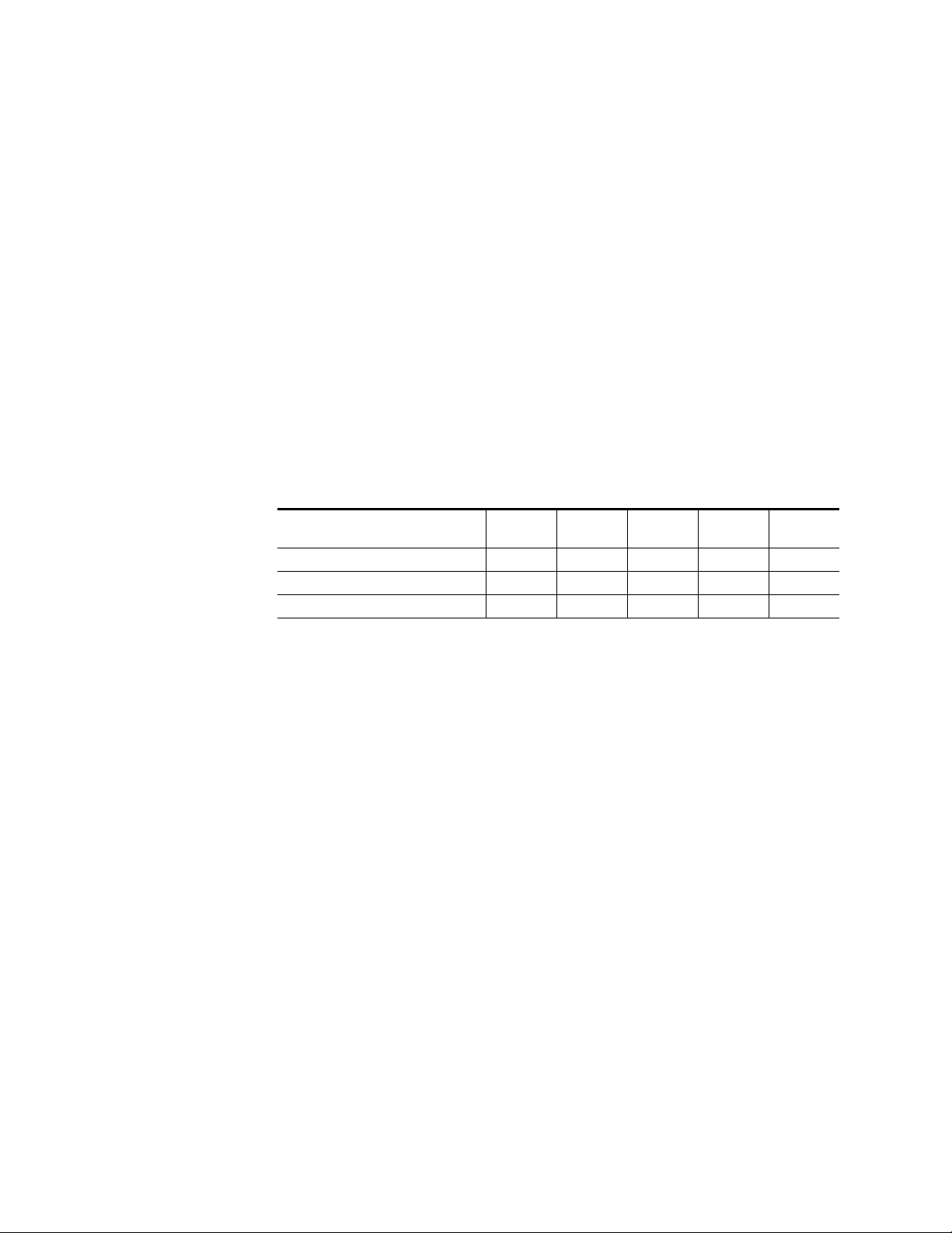
Frame Capacity
The maximum number of 8900 modules allowed in a frame is determined
by frame cooling capacity. Table 1 provides the power capacity, cooling
capacity, and maximum module count for the 8916 in each frame type.
Table 1. Power, Cooling, and Module Capacity of 8900 Frames
Capacity Calculated
Power (W) 60 60 100 100 100
Recommended Module Cooling (W) 30 60 30 90 90
8916 Modules 8 10 8 10 10
Note
Module capacity figures assume no other modules are in the frame.
If the maximum number of modules a frame can handle is less than ten,
provide as much space between the modules as possible.
8900T2
Frame
8900T2-F
Frame
8900TX
Frame
8900TF
Frame
8900TFN
Frame
2 8916 Instruction Manual
Page 9

Module Placement in the 8900 Frame
There are ten slot locations in the frame to accommodate either analog or
digital modules. These are the left ten locations. Refer to Figure 1.
The two slots on the right are allocated for the power supplies. For additional information concerning the Power Supply module, refer to the 8900
Power Supply manual.
The third slot from the right is allocated for the Controller module. This
module provides an interface for the SMPTE 269M fault reporting (health
alarm). For additional information concerning the Controller module, refer
to the 8900 Controller manual.
Figure 1. 8900 Series Frame
Installation
Any 8900 Module
Controller
Module
(only)
Power
Supplies
(only)
8900 modules are interchangeable within the module slots. There are 10
BNC connectors in each slot’s I/O group. The functional assignment of
each connector in a group is determined by the module that is placed in
that slot. The maximum number of modules an 8900 frame can accept is
ten. Figure 2 illustrates the rear connectors for an 8900 Series frame.
0614-03
8916 Instruction Manual 3
Page 10

8916 AES/EBU Auto-Tracking Delay DA
Figure 2. 8900 Series Frame Rear Connector
1.
2.
3.
10
J1 J2
O
J3 J4
U
T
J5 J6
J7 J8
J9 J10
IN
9
J1 J2
J2
O
J3 J4
J4
U
T
J5 J6
J6
J7 J8
J8
J9 J10
IN
8
J1 J2
O
J3 J4
U
T
J5 J6
J7 J8
J9 J10
IN
Note
7
J1 J2
J2
O
J3 J4
J4
U
T
J5 J6
J6
J7 J8
J8
J9 J10
IN
6
J1 J2
O
J3 J4
U
T
J5 J6
J7 J8
J9 J10
IN
5
J1 J2
J2
O
J3 J4
J4
U
T
J5 J6
J6
J7 J8
J8
J9 J10
IN
4
J1 J2
O
J3 J4
U
T
J5 J6
J7 J8
J9 J10
IN
At the back of this manual are die-cut overlay cards that can be placed over
3
J2
J1 J2
O
J4
J3 J4
U
T
J6
J5 J6
J8
J7 J8
J9 J10
IN
2
J1 J2
O
J3 J4
U
T
J5 J6
J7 J8
J9 J10
IN
J1 J2
J3 J4
J5 J6
J7 J8
the rear connector BNCs to identify the specific 8916 connector functions.
To install a module in the frame:
Insert the module, connector end first, with the component side of the
module facing to the right and the ejector tab to the top.
Verify that the module connector seats properly against the backplane.
Press the ejector tab in to seat the module in place.
1
O
U
T
J9 J10
IN
0585-03
Cabling
Loop-through Input
Connect an input source to one of the loop-through input connectors, J9 or
J10 (see Figure 3). The 8916 input will accept AES3id/EBU audio. Termi-
nate the unused connector into 75
Ω
if the signal is not looped to other
equipment.
4 8916 Instruction Manual
Page 11

Power Up
Outputs
Figure 3.
AES/EBUOutputs
Delay Input
from Frame Sync
AES/EBU
Loopthrough Input
Input/Output Connectors
8916
J3
J5
J7
DAx
O
U
T
J9 J10
IN
J2
J4
J6
J8
J2J1
AES/EBU
Outputs
J6
J8
0585-02
The 8916 has seven AES/EBU serial digital output connectors—J1 through
J6, and J8. The destination equipment should have a 75
or loop through inputs that are terminated into 75
Ω
input impedance
Ω
.
Power Up
Operation Indicator LEDs
Delay Input
A delay signal input BNC (J7) is provided for a reference signal from a
Grass Valley video sync generator (see Note page 1).
The various front LED indicators and configuration switches are illustrated
in Figure 4. Upon power-up, the green PWR LED should light and the
yellow CONF LED should illuminate for the duration of module initialization.
With factory default configuration and a valid input signal connected, the
green PWR LED, the yellow TRACK, and one of the green signal rate LEDs
should illuminate (refer to Table 2 on page 6 to see the possible operating
indicator combinations).
Audio input presence is indicated by the 32 kHz, 44.1 kHz, or 48 kHz LED
(indicating the module has locked to the indicated signal rate).
8916 Instruction Manual 5
Page 12

8916 AES/EBU Auto-Tracking Delay DA
Figure 4. LEDs and Configuration Switches
5
6
4
7
3
8
2
9
1
A
0
B
F
C
E
D
Ejector Tab
FAULT – Red diagnostic LED is off during normal operation
COMM – Yellow LED on during remote control communication
CONF – Yellow LED on when module is initializing or
processing control data
PWR – Green diagnostic LED on indicates power OK
32 kHz – Green LED on indicates lock to a 32 kHz signal
44.1 kHz – Green LED on indicates lock to a 44.1 kHz signal
48 kHz – Green LED on indicates lock to a 48 kHz signal
TRACK – Green LED on indicates auto delay is being added to the fixed delay
Coarse Delay Adjust
Rotary switch
5
6
4
7
3
8
2
1
0
F
E
D
9
A
B
C
Fine Delay Adjust
Rotary switch
REMOTE OVR – Yellow LED on indicates local switches and
0585_06
jumper settings are overridden by remote control
GND
A red FAULT LED indicates an error situation and, with the previously
described LEDs, can indicate the operational conditions presented in
Table 2. The table describes signal output and LED indications for various
input/reference combinations and user settings.
Table 2. Indicator LEDs and Conditions Indicated
LED Indication Condition
Off Normal operation
Fault
(red)
COMM
(yellow)
CONF
(yellow)
On continuously Module has detected internal fault
Long flash Configuration problem: Check inputs and settings
Short flash CRC (cyclic redundancy check) error detected
Off No activity on frame communication bus
Long flash Location Command received by the module from a remote control system
Short flash Activity present on the frame communication bus
Off Module is in normal operating mode
On continuously Module is initializing, changing operating modes or updating firmware
6 8916 Instruction Manual
Page 13

Table 2. Indicator LEDs and Conditions Indicated - (continued)
LED Indication Condition
PWR
(green)
32 kHz
(green)
44.1 kHz
(green)
48 kHz
(green)
REM OVR
(yellow)
Tracking
(yellow)
Off No power to module or module’s DC/DC converter failed
On continuously Normal operation, module is powered
Off Sample rate is not near 32 kHz
On Continuously Sample rate is 32 kHz ±400 ppm
Flashing Sample rate is 32 kHz ±4%
Off Sample rate is not near 44.1 kHz
On Continuously Sample rate is 44.1 kHz ±400 ppm
Flashing Sample rate is 44.1 kHz ±4%
Off Sample rate is not near 48 kHz
On Continuously Sample rate is 48 kHz ±400 ppm
Flashing Sample rate is 48 kHz ±4%
Off Module configuration is by the module’s on-board switches and jumpers
On continuously
Off Fixed delay only
On continuously
Module configuration is by remote control and on-board switches and jumpers are
overridden
Total operating delay is the sum of fixed and auto delay from frame sync delay input.
Front panel switches do not indicate total delay in this mode.
Power Up
8916 Instruction Manual 7
Page 14

8916 AES/EBU Auto-Tracking Delay DA
Configuration
The 8916 can be configured locally using onboard switches or remotely
using the 8900NET network interface. Configuration establishes:
■
Delay setting
■
Active or locked out remote control
Onboard Module Configuration
The 8916 can be configured using the rotary switches illustrated in Figure 5.
Delay Setting
For an AES/EBU signal the FINE switch delay increments are 2 ms (1/16
video frame), and the COARSE switch delay increments are 32 ms (one
video frame). Each switch can select up to 15 times its increment to create
a total delay of approximately 510 ms.
Remote Control Lockout
To make the 8916 module delay settings adjustable from the on-board
switches only, place a jumper across the Local Only pins on jumper block
JP3 illustrated in Figure 5. To have both Local and Remote access, set the
jumper on the two pins on the right side of the three-pin block.
Figure 5. Delay Adjustment Switches and Remote Lockout Jumper
CONF – configuration processing LED
Coarse
Delay adjust
Fine
rotary switches
JP3
Local only,
jumper across these
pins locks out
remote control
JP3
Local &
remote
active
0585_05
Remote Control Lockout
8 8916 Instruction Manual
Page 15

Remote Configuration and Monitoring
8916 configuration and monitoring can be performed using the 8900NET
interface in 8900TF or TFN frames (see Figure 6). This section describes the
GUI access to the module configuration functions. Refer to the 8900NET
Network Interface Module Instruction Manual for information on setting
up and operating the 8900 frame network.
For remote access, make sure the jumper block on the module is set to the
pins on the right for both Local and Remote access (Figure 5).
Configuration
Note
Figure 6. 8900NET GUI
The physical appearance of the menu displays shown in this manual represent the use of a particular platform, browser and version of 8900NET
module software. They are provided for reference only. Displays will differ
depending on the type of platform and browser you are using and the version
of the 8900NET software installed in your system.
The links section lists the frame and its current modules. The selected link's Status
page is first displayed and the sub-list of links for the selection is opened. The sub-list
allows you to select a particular information page for the selected device.
Content display section displays information for the selected
frame or module (frame slot icons are also active links).
The 8900 modules can be addressed by clicking on a specific module icon
in the frame status display or on a module name or slot number in the link
list on the left.
8916 Instruction Manual 9
Page 16

8916 AES/EBU Auto-Tracking Delay DA
The 8916 will indicate a SMPTE Alarm fault on the Frame Status display for
the following alarms:
Lack of valid audio input,
■
■
Internal Fault, or
■
Board Failure.
Module Configuration Displays
The 8900 GUI provides the following links and displays for the 8916
module. The module name shown in Figure 7 is “AES Audio Delay 3” (slot
number and module type). The name is user determined and is assigned
using the module’s Configuration display. The four module configuration
displays provide:
■
Module operational status information,
■
Module properties (part and version numbers),
■
Module configuration information (location and user assigned names),
and
■
Software update (file transfer).
These displays are the same for all remote controllable 8900 modules. Refer
to the 8900NET manual for more information on these displays. Some functions listed may not be supported by a particular module. These will be
indicated as not supported.
Figure 7. 8960DEC Display Links
Module Configuration
Displays
Signal Configuration
Display
Signal Configuration Display
This section discusses the Audio Delay display in the Signal Configuration
Display section used to set the amount of audio delay required in the 8916
module. You may set the audio delay using either the Numeric (Figure 8)
or Slider (Figure 9) adjustment mode. In either display mode, the changes
do not take place until the Apply button is clicked and the display is
refreshed.
10 8916 Instruction Manual
Page 17

Indicates total
amount of delay
Configuration
For an AES/EBU signal the FINE delay increments are 2 ms (1/16 video
frame), and the COARSE delay increments are 32 ms (one video frame).
Any settings selected will default to the nearest 2 ms or 32 ms increment.
Each adjustment can select up to 15 times its increment to create a total
delay of approximately 510 ms.
Figure 8 illustrates the Audio Delay display in numeric adjustment mode.
Figure 8. Audio Delay Display, Numeric Mode
Coarse Adjust (10x)
Fine Adjust (1x)
Indicates amount of
auto tracking delay
from Delay Input (J7)
Indicates state of
auto tracking
Indicates input
audio error status
Indicates Incoming
Sample Rate
DISABLED
AUDIO OK
48K
Set the amount of delay in Numeric mode by entering a number in the
Coarse Adjust and Fine Adjust boxes or use the arrow keys to change the
values. The number will default to an increment of 2mS (Fine) or 32 mS
(Coarse). The single arrows will increment the value by 1x and the double
arrows will increment the value by 10x.
Note
Numeric displays are for approximate values only. Calculation of displayed
values are subject to decimal place truncation. Variation from the absolute
value increases at higher values.
Use the Apply button to make the selections active.
8916 Instruction Manual 11
Page 18

8916 AES/EBU Auto-Tracking Delay DA
The sum of the Coarse, Fine and Auto Tracking delay will appear in the
Total Delay display above the Coarse and Fine Adjust.
Below the Coarse and Fine Adjust displays are the following indicators
giving module information:
■
Auto Tracking Delay: Amount of auto tracking delay in mS from the
Frame Sync Delay Input BNC (J7).
■
Auto Tracking State: Enabled or Disabled.
■
Input Audio Errors: Audio OK, Out of Range, GT (Greater Than) 4
Percent 48K, GT 4 Percent 44.1K, or GT 4 Percent 32K.
■ Incoming Sample Rate: 48K, 44.1K, 32K or Invalid.
Figure 9 shows the display for setting the delay in Slider mode.
Set Coarse and Fine delay using the arrow keys to increase or decrease the
delay. The settings will default to an increment of 2 mS (Fine) or 32 mS
(Coarse). The single arrows will change the value by 1x and the double
arrows will change the value by 10x.
Use the Apply button to make the selections active.
The sum of all delay is shown in the Total Delay slider display.
The module information below the Coarse and Fine Adjust displays is
identical to the information explained in the Numeric section above.
12 8916 Instruction Manual
Page 19

Indicates total
amount of delay
Coarse Adjust (10x)
Fine Adjust (1x)
Configuration
Figure 9. Audio Delay Display, Slider Mode
Indicates amount of
Auto Tracking
DISABLED
AUDIO OK
48K
8916 Instruction Manual 13
Page 20

8916 AES/EBU Auto-Tracking Delay DA
Specifications
Table 3. 8916 Specifications
Parameter Value
Digital Input
Signal type AES3id (1995)/EBU and SMPTE 276M - transformer coupled
Number of inputs 1 loop-through
Connector type 75 Ω BNC
Input return loss >25 dB (100 kHz-6 MHz)
Outputs
Number of outputs 7
Signal type AES3id (1995)/EBU and SMPTE 276M
Connector type 75 Ω BNC
Return loss >25 dB (100 kHz-6 MHz)
Intrinsic Jitter <6 ns
Performance
Sampling rates 32 kHz, 44.1 kHz, and 48 kHz
On-board delay adjustment Minimum 2 ms, Maximum 510 ms
Delay adjustment increments 2 ms
Tracking delay 20.8 µs to 30 ms
Environmental
Frame temperature range 0 to 45 degrees C
Operating humidity range 10 to 90% non-condensing
Non-operating temperature -10 to 70 degrees C
Mechanical
Frame type 8900 Series
Power Requirements
Supply voltage +12 V, -12V
Power consumption < 3.5 Watts
Minimum delay @ 32 kHz is 3 ms
14 8916 Instruction Manual
Page 21

Service
Service
The 8916 module makes extensive use of surface-mount technology and
programmed parts to achieve compact size and adherence to demanding
technical specifications. Circuit modules should not be serviced in the field.
If your module is not operating correctly, proceed as follows:
■ Check frame and module power and signal present LEDs.
■ Check for presence and quality of input signals.
■ Verify that source equipment is operating correctly.
■ Check cable connections.
■ Check output connections for correct I/O mapping (correct input con-
nector is used for the corresponding channel output).
Refer to Figure 4 for the location of PWR LED and Table 2 on page 6 for
proper LED indications.
If the module is still not operating correctly, replace it with a known good
spare and return the faulty module to a designated Tektronix repair depot.
Call your Tektronix representative for depot location.
Refer to the Contacting Grass Valley Group at the front of this document for
the Tektronix Customer Service Information number.
8916 Instruction Manual 15
Page 22

8916 AES/EBU Auto-Tracking Delay DA
Functional Description
Refer to the block diagram in Figure 10 while reading the following functional description.
Figure 10. 8916 Block Diagram
AES/EBU Input RX+
Loop-through
Delay Select Switches
Coarse
Fine
To Host
Delay Control I/F
RS 232
RX–
Controller
Receiver/
De-MUX
Power
Comm
Fault
Conf
Serial Data
SCK
F Sync
Error
Freq.
MCK
C
U
V
CBL
Field
Programmable
Gate Array
(FPGA)
Serial Data
SCK
F Sync
Parallel Data
Control
Parallel Data
32 kHz
44.1 kHz
48 kHz
Tracking
Remote Override
MUX
FIFO
AES/EBU
Serial
Data
Outputs
Line
Drivers
Input Receiver
AES/EBU audio data is fed into the 8916 through an isolation transformer
where it is received by the receiver chip. The receiver recovers the clock and
synchronization signals, and demultiplexes the audio and digital data.
FPGA Delay Section
The delay section receives the 12.29 MHz clock, synchronization information, frequency information, and error status information. It also receives
the switch position settings that determine the fixed length of delay.
16 8916 Instruction Manual
Page 23

Delay FIFO
The FIFO receives parallel data from the FPGA. The FPGA provides all
clock and control signals. The FIFO output is sent back to the FPGA.
The capacity of the FIFO is 262214 x 12 bits. A single audio sample is 48 bits
of data. With a sampling rate of 48 kHz the maximum delay of the card is
510 ms.
Transmitter/Multiplexer Circuit
The serial data, after being delayed, is routed to the Interface Transmitter
from the FPGA. The Transmitter multiplexes the channel, user, and validity
data from the receiver chip with the serial audio data from the FPGA.
Line Drivers
The line driver chip drives seven output lines. The outputs feed an RC
network that:
Functional Description
■ Attenuates the signal to one volt peak-to-peak
■ Limits the risetime to meet the AES specification, and
■ Creates a 75 Ω output resistance to match the cable impedance.
Delay Adjustment Switches
There are two rotary output timing adjustment switches:
■ A fine-step adjustment switch provides sixteen 2ms timing steps
■ A coarse-step adjustment switch provides sixteen 32ms timing steps
The switches provide output timing adjustable from 2ms to 510ms with
respect to the input.
Audio Delay Control Interface
The 8916 auto delay control input consists of a one wire serial signal using
RS232 voltage levels, input on a coaxial BNC connector (Delay Input).
Delay values can range from 0 to 3FF(hex).
8916 Instruction Manual 17
Page 24

8916 AES/EBU Auto-Tracking Delay DA
Controller
The controller provides the interface between the user and all the processing logic inside the 8916. It also supports communications between an
external host processor and the 8916.
18 8916 Instruction Manual
Page 25

Index
A
auto delay 17
frame status display 9
B
backplane 4
block diagram 16
C
clock 16
connector
delay signal
connectors 3
input 4
controller 18
controller module 3
5
D
delay 8
local adjustment 8, 17
remote adjustment 11
delay input 5
E
G
GUI 9
I
impedance 5
indicators 5, 6
input
loopthrough
receiver 16
termination 4
J
jumper 8
L
LEDs 5
line driver 17
links 10
local control 8
4
environmental 14
F
factory default 5
fault 6
fault report 10
features 1
FIFO 17
FPGA 16
frame 14
8916 Instruction Manual Index-1
M
module
controller
installation 3
power supply 3
slots 3
module name 10
multiplexer 17
3
Page 26

N
network 9
O
onboard module configuration 8
delay setting 8
remote control lockout 8
operational modes 6
outputs 14
connectors 5
termination 5
overlay 4
P
performance 14
power 14
power supply 3
power-up 5
processing logic 18
R
remote configuration and monitoring 9
audio delay display 10
remote lockout 8
repair depot 15
S
setting delay 8
SMPTE alarm 10
sync generator 5
T
termination 4
transmitter 17
troubleshooting 15
V
voltage 14
Index-2 8916 Instruction Manual
 Loading...