

Page 1
8901/8902/8906
ANALOG VIDEO DISTRIBUTION AMPLIFIERS
Instruction Manual
SOFTWARE VERSION 1.0.0
071827100
FEBRUARY 2004
Page 2

Contacting Grass Valley
Region Voice Fax Address Web Site
North America (800) 547-8949
Support: 530-478-4148
Pacific Operations +852-2585-6688
Support: 852-2585-6579
U.K., Asia, Middle East +44 1753 218 777 +44 1753 218 757
France +33 1 45 29 73 00
Germany, Europe +49 6150 104 782 +49 6150 104 223
Copyright © Thomson Broadcast and Media Solutions All rights reserved.
Grass Valley Web Site
Sales: (530) 478-3347
Support: (530) 478-3181
+852-2802-2996
Grass Valley
P.O. Box 599000
Nevada City, CA 959597900 USA
www.thomsongrassvalley.com
The www
Online User Documentation
.thomsongrassvalley.com web site offers the following:
— Current versions of product catalogs, brochures,
data sheets, ordering guides, planning guides, manuals, and release notes
in .pdf format can be downloaded.
FAQ Database
— Solutions to problems and troubleshooting efforts can be
found by searching our Frequently Asked Questions (FAQ) database.
Software Downloads
— Software updates, drivers, and patches can be down-
loaded.
2 8901/8902/8906 Instruction Manual
Page 3

Contents
Preface
. . . . . . . . . . . . . . . . . . . . . . . . . . . . . . . . . . . . . . . . . . . . . . . . . . . . . . . . . . . . . . . . . . . . . 5
About This Manual . . . . . . . . . . . . . . . . . . . . . . . . . . . . . . . . . . . . . . . . . . . . . . . . . . . . . 5
8901/8902/8906
Analog Video DA Modules
Introduction . . . . . . . . . . . . . . . . . . . . . . . . . . . . . . . . . . . . . . . . . . . . . . . . . . . . . . . . . . . 7
8901 Video DA . . . . . . . . . . . . . . . . . . . . . . . . . . . . . . . . . . . . . . . . . . . . . . . . . . . . . . . 8
8902 Video DA . . . . . . . . . . . . . . . . . . . . . . . . . . . . . . . . . . . . . . . . . . . . . . . . . . . . . . . 8
8906 Video DA . . . . . . . . . . . . . . . . . . . . . . . . . . . . . . . . . . . . . . . . . . . . . . . . . . . . . . . 8
Installation . . . . . . . . . . . . . . . . . . . . . . . . . . . . . . . . . . . . . . . . . . . . . . . . . . . . . . . . . . . . 9
On-board Jumper Settings . . . . . . . . . . . . . . . . . . . . . . . . . . . . . . . . . . . . . . . . . . . . . 9
Equalization – J2. . . . . . . . . . . . . . . . . . . . . . . . . . . . . . . . . . . . . . . . . . . . . . . . . . . 10
DC Restore/AC or DC Coupling – J4 . . . . . . . . . . . . . . . . . . . . . . . . . . . . . . . . . 11
Clamp – J5 . . . . . . . . . . . . . . . . . . . . . . . . . . . . . . . . . . . . . . . . . . . . . . . . . . . . . . . . 11
White Clip – JP3 . . . . . . . . . . . . . . . . . . . . . . . . . . . . . . . . . . . . . . . . . . . . . . . . . . . 11
Module Placement In Frame . . . . . . . . . . . . . . . . . . . . . . . . . . . . . . . . . . . . . . . . . . 12
Gecko 8900 Frame . . . . . . . . . . . . . . . . . . . . . . . . . . . . . . . . . . . . . . . . . . . . . . . . . 12
8500 Frames. . . . . . . . . . . . . . . . . . . . . . . . . . . . . . . . . . . . . . . . . . . . . . . . . . . . . . . 14
8800 Frames. . . . . . . . . . . . . . . . . . . . . . . . . . . . . . . . . . . . . . . . . . . . . . . . . . . . . . . 15
Cabling . . . . . . . . . . . . . . . . . . . . . . . . . . . . . . . . . . . . . . . . . . . . . . . . . . . . . . . . . . . . 15
Loop-Through Input . . . . . . . . . . . . . . . . . . . . . . . . . . . . . . . . . . . . . . . . . . . . . . . 15
Outputs . . . . . . . . . . . . . . . . . . . . . . . . . . . . . . . . . . . . . . . . . . . . . . . . . . . . . . . . . . 15
Power Up . . . . . . . . . . . . . . . . . . . . . . . . . . . . . . . . . . . . . . . . . . . . . . . . . . . . . . . . . . . . 16
Operation Indicator LEDs . . . . . . . . . . . . . . . . . . . . . . . . . . . . . . . . . . . . . . . . . . . . 16
Module Adjustments . . . . . . . . . . . . . . . . . . . . . . . . . . . . . . . . . . . . . . . . . . . . . . . . . . 17
Gain Adjustment . . . . . . . . . . . . . . . . . . . . . . . . . . . . . . . . . . . . . . . . . . . . . . . . . . . . 17
Equalization Adjustment . . . . . . . . . . . . . . . . . . . . . . . . . . . . . . . . . . . . . . . . . . . . . 17
White Clip Adjustment. . . . . . . . . . . . . . . . . . . . . . . . . . . . . . . . . . . . . . . . . . . . . . . 17
Remote Monitoring. . . . . . . . . . . . . . . . . . . . . . . . . . . . . . . . . . . . . . . . . . . . . . . . . . . . 18
Links and Web Pages. . . . . . . . . . . . . . . . . . . . . . . . . . . . . . . . . . . . . . . . . . . . . . . 20
Status Web Page. . . . . . . . . . . . . . . . . . . . . . . . . . . . . . . . . . . . . . . . . . . . . . . . . . . 21
Video Input Status Web Page. . . . . . . . . . . . . . . . . . . . . . . . . . . . . . . . . . . . . . . . 22
Slot Config Web Page . . . . . . . . . . . . . . . . . . . . . . . . . . . . . . . . . . . . . . . . . . . . . . 23
Software Update Web Page . . . . . . . . . . . . . . . . . . . . . . . . . . . . . . . . . . . . . . . . . 25
Specifications . . . . . . . . . . . . . . . . . . . . . . . . . . . . . . . . . . . . . . . . . . . . . . . . . . . . . . . . . 26
Functional Description . . . . . . . . . . . . . . . . . . . . . . . . . . . . . . . . . . . . . . . . . . . . . . . . . 27
Input Amplifier . . . . . . . . . . . . . . . . . . . . . . . . . . . . . . . . . . . . . . . . . . . . . . . . . . . . . 27
Equalizing Amplifier. . . . . . . . . . . . . . . . . . . . . . . . . . . . . . . . . . . . . . . . . . . . . . . . . 27
Output Driver. . . . . . . . . . . . . . . . . . . . . . . . . . . . . . . . . . . . . . . . . . . . . . . . . . . . . . . 28
Microprocessor. . . . . . . . . . . . . . . . . . . . . . . . . . . . . . . . . . . . . . . . . . . . . . . . . . . . . . 28
Power Supply. . . . . . . . . . . . . . . . . . . . . . . . . . . . . . . . . . . . . . . . . . . . . . . . . . . . . . . 28
Service. . . . . . . . . . . . . . . . . . . . . . . . . . . . . . . . . . . . . . . . . . . . . . . . . . . . . . . . . . . . . . . 29
Status Monitoring . . . . . . . . . . . . . . . . . . . . . . . . . . . . . . . . . . . . . . . . . . . . . . . . . . . . . 30
8901/8902/8906 Instruction Manual 3
Page 4

Contents
LEDs . . . . . . . . . . . . . . . . . . . . . . . . . . . . . . . . . . . . . . . . . . . . . . . . . . . . . . . . . . . . . . 30
Frame Alarm . . . . . . . . . . . . . . . . . . . . . . . . . . . . . . . . . . . . . . . . . . . . . . . . . . . . . . . 31
Web Browser Interface. . . . . . . . . . . . . . . . . . . . . . . . . . . . . . . . . . . . . . . . . . . . . . . 31
SNMP Reporting . . . . . . . . . . . . . . . . . . . . . . . . . . . . . . . . . . . . . . . . . . . . . . . . . . 32
Index
. . . . . . . . . . . . . . . . . . . . . . . . . . . . . . . . . . . . . . . . . . . . . . . . . . . . . . . . . . . . . . . . . . . . . . 33
4 8901/8902/8906 Instruction Manual
Page 5

Preface
About This Manual
This manual describes the features of a specific module of the Gecko 8900
Signal Processing System. As part of this module family, it is subject to
Safety and Regulatory Compliance described in the Gecko 8900 Series
frame and power supply documentation (see the
Frames Instruction Manual
8900TX/8900TF/8900TFN
).
8901/8902/8906 Instruction Manual 5
Page 6

Preface
6 8901/8902/8906 Instruction Manual
Page 7

8901/8902/8906 Analog Video DA Modules
Introduction
The 8901, 8902 and 8906 Analog Video Distribution Amplifier modules are
a series of precision DAs for distributing analog video. All modules offer
excellent differential gain and phase and common mode rejection specifications.
Each 8900 DA module features:
• Passive differential loop-through input for excellent common mode
hum rejection even when cable runs are adjacent to AC Mains cables,
•Distribution of NTSC, PAL, SECAM, RGB, YUV, and Tri-level Sync
video,
• Installs in the 8900, 8800, and 8500 Grass Valley frames with:
• Eight outputs in 8900 and 8800 Series frames,
• Six outputs in 8500 Series frames, and
•Card edge gain control.
A comparison of module functions for the 8900 Analog Video DA Series is
given in Table 1.
Table 1. 8900 Analog Video DA Comparison
Function 8901 8902 8906
Card edge gain adjustment X X X
DC/AC coupling X X X
DC restoration – X X
Card-edge adjust equalization – X X
Fast or slow clamping – – X
White clip threshold adjustment – – X
Remote monitoring – – X
8901/8902/8906 Instruction Manual 7
Page 8

Introduction
8901 Video DA
8902 Video DA
The 8901 is a utility DA ideal for short cable runs of high quality signals. A
flat frequency response and impressive signal-to-noise ratio enable high
quality copies of the input signal to all eight outputs.
The 8902 Equalizing DA offers the same features as the 8901 Utility DA as
well as input cable equalization which accurately compensates for attenuation and phase errors induced in long cable runs. The cable equalization
is custom-designed for each specific cable type. In addition to the DC and
AC coupling modes is a DC restoration mode which smoothly restores the
blanking level DC component to zero volts.
8906 Video DA
The 8906 Clamping DA with input presence detection offers the same features as the 8901 and 8902 modules plus a dual speed clamp which provides flexibility with clamp-induced noise versus single-ended hum
rejection. A white clip control can be enabled to eliminate positive-going
pulses above a user-selected threshold.
Also included on the 8906 module is a video presence detection circuit that
generates SNMP traps when video is not present. Control of SNMP
reporting can be enabled and disabled by the user with the available
remote controls in 8900 video frames.
8 8901/8902/8906 Instruction Manual
Page 9

Installation
On-board Jumper Settings
1.
3.
Installation of the 8900 Analog Video DA modules is a process of:
Setting on-board module jumper settings for desired operation
(page 9),
2.
Placing the module in the proper video frame slot (page 12), and
Cabling and terminating signal ports (page 15).
The DA module can be plugged in and removed from the frame with
power on. When power is applied to the module, LED indicators reflect the
initialization process (see Power Up on page 16).
Installation
Each 8900 Analog Video DA module requires jumper settings to determine
the desired operating modes as outlined in Table 2 and shown in Figure 1.
Table 2. On-board Jumper Settings
Jumper/Function 8901 8902 8906
J2 – Equalization N/A
J4 – Coupling
J5 – Clamp (8906) N/A N/A
JP3– White Clip (8906) N/A N/A On or Off
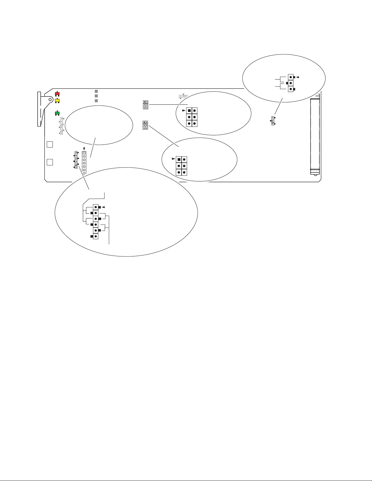
Figure 1 on page 10 illustrates each of the on-board jumpers on the circuit
board. Note that depending on the model, some components may not be
present. For details on setting each jumper, refer to the specific jumper
headings given in this section.
DC or AC
Coupling
0 – 500’ or 500 – 1000’
(0 – 150 m or 150 – 300 m)
DC Restore, DC, or AC coupling DC Restore, DC, or AC coupling
0 – 500’ or 500 – 1000’
(0 – 150 m or 150 – 300 m)
Clamp On or Off,
Fast or Slow clamp
8901/8902/8906 Instruction Manual 9
Page 10
Installation
GAIN
EQ
Figure 1. On-board Jumpers
GRASS VALLEY 8901 ANALOG VIDEO DA
8902
8906
Equalizer for specific cable
type should be installed
in J3 for 8902 and 8906.
J3
J2
EQUALIZATION
(8902 and 8906)
0' – 500' (1-2 and 3-4)
WHITE CLIP
(8906 only)
OFF (1-2)
ON (2-3)
J4
J5
J5
COUPLING
J4
DC RESTORE (1-2)
DC COUPLED (3-4)
AC COUPLED (5-6)
CLAMP
(8906 only)
ON (1-2)
ON (3-4)
FAST (5-6)
JP3
JP3
8271_06
1
J2
500' – 1000' (2-3 and 4-5)
Equalization – J2
On the 8902 and 8906 modules, an equalizer for the specific cable type
being used with this module is installed in location J3.
Set jumper J2 to match your maximum cable length as follows:
•0 to 500 ft. (150 m) – set J2 to pins 1-2 and 3-4.
• 500 ft. (150 m) to 1000 ft. (300 m) – set J2 to pins 2-3 and 4-5.
Use the front edge EQ adjustment, R2, to fine tune the equalization as
described in
Equalization Adjustment
on page 17.
10 8901/8902/8906 Instruction Manual
Page 11

DC Restore/AC or DC Coupling – J4
On all of these modules, set jumper J4 for the type of coupling desired:
• DC Restore (8902 and 8906) – set J4 to pins 1-2 for DC restoration. DC
restoration smoothly restores the blanking level DC components to
zero volts. This DC restoration circuit functions with or without synchronization pulses and can therefore be used with GBR or YUV signals.
• DC Coupled – set J4 to pins 3-4 for DC Coupled mode. The DC Coupled
mode is recommended when distributing color difference signals (B-Y,
R-Y) or for simple non-reclocking fanout distribution of AES/EBU
1 V p-p coaxial digital audio signals.
• AC Coupled – set J4 to pins 5-6 for AC Coupled mode. Use the AC
Coupled mode when the incoming video signal has its blanking level
at anything other than zero volts.
Installation
Clamp – J5
The 8906 module has a clamp control that can be enabled or disabled and
the clamp speed set to fast or slow. When enabled, the clamping function
will override the coupling mode set with jumper J4.
On the 8906 module, set jumper J5 to enable and disable clamping and set
clamping speed as follows:
•Clamp Off – remove the shorting jacks on J5 on pins 1-2 and 3-4. You
may store the shorting jacks on pin 1 and pin 3. The clamp speed
shorting jack on pins 5-6 can be left in any position.
• Fast Clamp On – set the shorting jacks on J5 to pins 1-2, 3-4, and 5-6.
Also set jumper J4 for AC Coupled, pins 5-6. Use a fast clamp for applications where greater hum rejection is required.
• Slow Clamp On – set the shorting jacks on J5 to pins 1-2, and 3-4.
Remove the shorting jack from pins 5-6. Store the jack on pin 5. Also set
jumper J4 for AC Coupled, pins 5-6. Slow clamping is useful in applications where noise suppression is required.
White Clip – JP3
The 8906 module has a White Clip control that can be enabled to eliminate
positive-going pulses above a user-selected threshold set by the White Clip
Level potentiometer, R95.
On the 8906 module, set jumper JP3 to enable or disable the White Clip control:
•White Clip Off – set JP3 to pins 1-2.
•White Clip On – set JP3 to pins 2-3.
8901/8902/8906 Instruction Manual 11
Page 12

Installation
Module Placement In Frame
8901, 8902, and 8906 Analog Video DA modules can be installed in Gecko
8900 frames and also older version (legacy) 8500 or 8800 Grass Valley
frames.
Remote monitoring is available only with an 8906 module installed in a
Gecko 8900TFN-V or 8900TFN video frame (with an 8900NET module
installed).
Note
8900 Analog Video DA modules installed in 8500 frames require a trace cut
as shown in Figure 4 on page 14.
Gecko 8900 Frame
There are ten cell locations in the 8900 video frame to accommodate modules. These are the left ten locations (Figure 2).
The two cells on the right are allocated for the power supplies. For additional information concerning the Power Supply module, refer to the 8900
Power Supply manual.
The third cell from the right is allocated for the Frame Monitor or 8900NET
Network Interface module. These modules provide health monitoring and
control options for modules with remote monitoring and control capability.
Figure 2. Gecko 8900 Series Frame
Any 8900 Module
Frame Controller or
8900NET Network
Interface Module
12 8901/8902/8906 Instruction Manual
Power
Supplies
(only)
8271_04
Page 13

1.
2.
3.
Installation
8900 Frame Capacity
These modules can be installed in all Gecko 8900 video frames but with
varying maximum quantities determined by frame cooling capacity.
Table 3 provides the power capacity, cooling capacity, and maximum
module count for each frame type.
Table 3. Video Frame Power Capacity
Capacity Calculated 8900TX Frame 8900TF Frame 8900TFN Frame
Power (W) 100 100 100
Recommended Module Cooling (W) 30 90 90
8900 DA Modules 10 10 10
DA10
J1 J2
O
J3 J4
U
T
J5 J6
DA9
J1 J2
J2
O
J3 J4
J4
U
T
J5 J6
J6
Note
Module capacity figures assume no other modules are in the frame.
To install a module in the frame:
Insert the module, connector end first, with the component side of the
module facing to the right and the ejector tab to the top.
Verify that the module connector seats properly against the backplane.
Press in the ejector tab to seat the module.
Note
Figure 3. Gecko 8900 Series Video Frame Rear Connector
J1 J2
J3 J4
J5 J6
8900 module slots are interchangeable within the frame. There are 10 BNCs
in each slot’s I/O group. The functional assignment of each connector in a
group is determined by the module that is placed in that slot. The maximum
number of modules a Gecko 8900 video frame can accept is ten. Figure 3
illustrates the rear connector plate for a Gecko 8900 video frame.
DA8
O
U
T
DA7
J1 J2
J2
O
J3 J4
J4
U
T
J5 J6
J6
DA6
J1 J2
O
J3 J4
U
T
J5 J6
DA5
J1 J2
J2
O
J3 J4
J4
U
T
J5 J6
J6
DA4
J1 J2
O
J3 J4
U
T
J5 J6
DA3
J2
J1 J2
O
J4
J3 J4
U
T
J6
J5 J6
DA2
J1 J2
O
J3 J4
U
T
J5 J6
J1 J2
J3 J4
J5 J6
DA1
O
U
T
J7 J8
J9 J10
IN
J7 J8
J8
J9 J10
IN
J7 J8
J9 J10
IN
J7 J8
J8
J9 J10
IN
J7 J8
J9 J10
IN
J7 J8
J8
J9 J10
IN
J7 J8
J9 J10
IN
J8
J7 J8
J9 J10
IN
J7 J8
J9 J10
IN
J7 J8
J9 J10
IN
8271_03
8901/8902/8906 Instruction Manual 13
Page 14

Installation
8500 Frames
Modules installed in an 8500 frame must first be modified with a trace cut
in order to work properly. Cut the trace in the place indicated by the silkscreen on the module as illustrated in Figure 4.
GAIN
EQ
Note
Figure 4. Module Trace Cut for 8500 Frame Operation
GRASS VALLEY 8901 ANALOG VIDEO DA
8902
8906
J2
Cutting the trace will disable the module for use in an 8800 or 8900 frame. If
the module is needed in a newer frame type, the cut trace may be bridged.
J4
J5
JP3
8271_10
DA10
J1
O
U
J3
T
J5
IN
J9 J10
DA9
J2
J1
O
U
J3
J4
T
J6
J6
J5
IN
J9 J10
The 8500 frame provides the same looping BNC analog input with six
outputs as shown in Figure 5. Remote control with the 8900NET module is
not available in the 8500 frame.
Figure 5. 8500 Frame Rear BNCs
DA8
J2
J1
O
U
J3
J4
J6
J6
J5
IN
J9 J10
T
DA7
J2
J1
O
U
J3
J4
T
J6
J6
J5
IN
J9
DA6
J2
J1
O
U
J3
J4
T
J6
J6
J5
IN
J10
J9
J2
J1
J3
J4
J6
J6
J5
J10
J9 J10
DA5
O
U
T
IN
DA4
J2
J1
J3
J4
J6
J6
J5
J9 J10
O
U
T
IN
DA3
J2
J1
J3
J4
J6
J6
J5
J9 J10
O
U
T
IN
DA2
J2
J1
J3
J4
J6
J6
J5
J9 J10
O
U
T
IN
J2
J1
J3
J4
J6
J5
J9 J10
DA1
J2
O
U
J4
T
J6
8271_08
IN
14 8901/8902/8906 Instruction Manual
Page 15

8800 Frames
Cabling
Installation
The 8800 frame provides the same looping BNC analog input with eight
outputs (Figure 3 on page 13). Remote control with the 8900NET module is
not available in the 8800 frame.
Refer to Figure 6 for cabling the 8900 Analog Video DA module in an
8900/8800 frame. Only the first six outputs are available when a module is
installed in the 8500 frame. Cabling to and from the module is done at the
back of the video frame as described below.
Note
At the back of every hardcover manual are overlay cards that can be placed
on the rear connector BNCs to identify the specific connector functions.
Loop-Through Input
One analog video input is provided at loop-through BNCs J9 and J10. If the
unused input is not looped to another device, it should be terminated in
75
Ω .
Outputs
There are eight outputs from each 8900 Analog Video DA module at BNCs
J1 through J8. Output destination equipment should have an input impedance of 75
loop-through inputs must be terminated into 75
Figure 6. 8900 DA Rear Input/Output Connectors
Analog output
Analog output
Analog output
Ω unless it has loop-through inputs, in which case the
Ω .
J3
DAx
O
U
T
J2
J4
J2J1
J4
Analog output
Analog output
Analog output
J6
J8
J6
Analog output
J8
8271_01
Analog output
Loop-through
Analog Video Input
J5
J7
J9 J10
IN
8901/8902/8906 Instruction Manual 15
Page 16

Power Up
Power Up
The front LED indicators and configuration switches are illustrated in
Figure 7. Upon power-up, the green PWR LED present on all module types
should light.
Figure 7. LEDs and Configuration Switches
GRASS VALLEY 8901 ANALOG VIDEO DA
8902
FAULT
8906
COMM
PWR
GAIN
EQ
Operation Indicator LEDs
Refer to Figure 7 and Table 4 for the name and meaning of each of the board
edge operating indicators on the module circuit board.
Table 4. Board Edge LED Names and Meaning
LED Indication Condition
FAULT
(red)
8906 only
COMM
(yellow)
8906 only
PWR
(green)
Off Normal operation.
On continuously 8906 module has detected an internal fault.
Long Flash Input missing and report loss of signal function is enabled.
Off No activity on frame communication bus.
Short flash
Off No power to module or module’s DC/DC converter failed.
On continuously Normal operation, module is powered.
Activity present on the frame communication bus or Locate Module command received by the
module from a remote control system.
8271_02
16 8901/8902/8906 Instruction Manual
Page 17

Module Adjustments
The following adjustments can be made from front edge and on-board controls on the module circuit board. There are no remote control adjustments.
Gain Adjustment
Overall gain of the outputs on these modules can be adjusted ± 2 dB with
the front edge GAIN potentiometer R1. To adjust gain:
1.
Connect one of the output BNCs to a waveform monitor.
2.
Adjust the input signal to the desired amplitude with the GAIN
potentiometer.
Module Adjustments
Equalization Adjustment
On the 8902 and 8906 modules, equalization can be fine tuned with the
front edge EQ potentiometer, R2.
To fine turn equalization:
Connect a test signal such as Multiburst (up to 20 MHz) to the module
1.
input and terminate the unused loop-through input.
Use the front edge EQ potentiometer to adjust for equal frequency
2.
response on the multiburst signal while monitoring an output from the
module.
White Clip Adjustment
The white clip level of the signal can be set with the White Clip Level
adjustment, R95. The adjustment range is from 500 mV to 1200 mV.
To adjust the white clip:
Set jumper JP3 to On (pins 2-3) and place the module on an extender if
1.
possible.
Connect an output BNC to a waveform monitor.
2.
Connect 100% Color Bars to the input. Use one of the following
3.
methods to make the adjustment:
a.
Unterminate the output you are monitoring and adjust the white
portion of the signal to be below 1 V.
Leave the output terminated and adjust the white portion to clip
b.
where desired for your application.
8901/8902/8906 Instruction Manual 17
Page 18

Remote Monitoring
Remote Monitoring
8906 module monitoring can be performed using a web browser GUI interface when the 8900NET Network Interface module is present in the Gecko
8900TFN-V frame. Remote monitoring is not possible with the 8500 or 8800
frames. This section describes the GUI access to the available module functions.
Refer to the 8900NET Network Interface Module Instruction Manual for information on the 8900NET Network Interface module and setting up and
operating the Gecko 8900 frame network.
Note For optimal performance and access to the latest features, it is recommended
Refer to the Frame Status page shown in Figure 8 on page 19. The 8900
modules can be addressed by clicking either on a specific module icon in
the frame status display or on a module name or slot number in the link list
on the left.
that the 8900NET module be updated to the latest software release. Check the
Grass Valley web site for the current 8900NET software.
Note The physical appearance of the menu displays on the web pages shown in
this manual represent the use of a particular platform, browser and version
of 8900NET module software. They are provided for reference only. Displays
will differ depending on the type of platform and browser you are using and
the version of the 8900NET software installed in your system.
Use the Refresh button to update the display (available with 8900NET software version 3.2.0 and later).
The
Online Manual Link button can be set up to link to the documentation in
pdf format. Link configuration is done on the Frame Configuration page.
For information on status and fault monitoring and reporting shown on the
Status page, refer to Status Monitoring on page 30.
18 8901/8902/8906 Instruction Manual
Page 19

Figure 8. Frame Status Page
8270_04
The Links section lists the frame and its current modules. The selected link's Status
page is first displayed and the sub-list of links for the selection is opened. The sub-list
allows you to select a particular information page for the selected device.
Content display section displays the information page
for the selected frame or module (frame slot icons are also
active links).
Online Manual Link
Refresh button for manual
update of page
Remote Monitoring
8901/8902/8906 Instruction Manual 19
Page 20

Remote Monitoring
Links and Web Pages
The 8900 GUI provides the following links and web pages for the 8906
module (Figure 9):
• Status – reports input and frame bus status and module information
(page 21),
•Video Input Status – status reporting for the video input can be enabled
or disabled (page 22),
• Slot Config – provides a Locate Module function and Slot Memory
(page 23), and
• Software Update – gives information about software updating
(page 25).
Figure 9. 8906 Web Page Links
20 8901/8902/8906 Instruction Manual
Page 21

Status Web Page
Remote Monitoring
Use
this
link
The Status web page (Figure 10) shows the signal status of the analog video
input and frame bus communication. Color coding of the display indicates
the signal status. Refer to Status Monitoring on page 30 for an explanation
of the color coding.
Information about the module, such as part number, serial number, hardware revision and software versions are given in a read-only section at the
bottom of the display.
Figure 10. 8906 Status Web Page
8901/8902/8906 Instruction Manual 21
Page 22

Remote Monitoring
Video Input Status Web Page
Use
this
link
The Video Input Status web page (Figure 10) allows enabling or disabling
reporting of signal loss.
To enable loss of signal reporting, select
reporting of signal loss, select
Disabling this control will gray out the Input signal on the Status web page
graphic shown in Figure 10 on page 21.
No.
Yes from the pulldown. To disable
Press the
Figure 11. 8906 Video Input Status Web Page
Apply button to enter the selection.
22 8901/8902/8906 Instruction Manual
Page 23

Slot Config Web Page
Use the Slot Config web page (Figure 12 on page 24) to perform the following functions on the 8906 module:
Remote Monitoring
Use
this
link
•
Locate Module – selecting the Flash radio button flashes the COMM and
FAULT LEDs on the front of the module so it can be located in the
frame.
•
Slot Identification – You may identify the module by typing a specific
name in the
module and travels with the 8900NET module if it is moved to another
frame. Select
•
Slot Memory – the slot configuration for each media module is automati-
cally saved periodically (once an hour) to the 8900NET module in that
frame. You may also select the
save the current configuration for this slot. The configuration is saved
on the 8900NET module. If the 8900NET module is removed or
powered down, the stored configurations are not saved.
When the
ration saved to this slot is saved as slot memory. When the current
module is removed and another module of the same type is installed,
the configuration saved to the 8900NET module will be downloaded to
the new module. The box must be checked before the current module
with the saved configuration is removed.
•
Hardware Switch Controls – a read-only status report of 8900NET module
switch settings for Module Status Reporting and Asynchronous Status
Reporting. These functions must be enabled for the following Slot
SNMP Trap Reports to function.
Name field. The assigned name is stored on the 8900NET
Default to enter the factory default module name.
Learn Module Config button at any time to
Restore upon Install box has been checked, the current configu-
•
Slot SNMP Trap Reports – displayed only when the SNMP Agent software
has been installed on the 8900NET module. Slot SNMP traps can be
enabled only when the hardware switches for Module Fault reporting
and Asynchronous Status reporting are in enabled on the 8900NET
module (dipswitch S1 segment 7 and dipswitch S2 segment 1).
The enabled SNMP traps will be reported to any SNMP manager that
is identified as an SNMP Report Destination in 8900NET configuration.
Trap severity is read-only hard-coded information that is interpreted
and responded to by the SNMP Manager software configuration.
SNMP reporting can be also be disabled for the video input on the
Video Input Status web page (page 22).
8901/8902/8906 Instruction Manual 23
Page 24

Remote Monitoring
Figure 12. 8937 Slot Config Page
24 8901/8902/8906 Instruction Manual
Page 25

Use
this
link
Remote Monitoring
Software Update Web Page
The Software Update web page (Figure 13) indicates that module software
updates via the web or using the NetConfig networking application are not
supported.
For complete software updating instructions for the 8906, refer to the
release notes included with the software upgrade.
Figure 13. 8906DA Software Update Web Page
8901/8902/8906 Instruction Manual 25
Page 26

Specifications
Specifications
Table 5. 8901, 8902, 8906 Analog Video DA Module Specifications
Parameter Value
Analog Video Input
Number of inputs 1 (BNC loop-through)
Impedance Passive high impedance differential loop-through
Input format Analog video: NTSC, PAL, SECAM, RGB, YUV, Tri-level sync
Input level Video 1 V p-p, Subcarrier up to 2 V p-p
Return loss > 40 dB up to 5 MHz
CMRR > 66 dB 50/60 Hz
Common mode input range ± 10 V
Analog Video Outputs
Number of outputs 8 in 8900/8800 frame, 6 in the 8500 frame
Output impedance 75 Ω
Signal level 1 V p-p ± 2 dB
Return loss > 40 dB up to 5 MHz
Output DC < 50 mV
Performance
Frequency Response 8901 and 8902:
± 0.025 dB to 5 MHz
± 0.05 dB to 8 MHz
–1 dB at 16 MHz
8906:
± 0.05 dB to 5 MHz
± 0.1 dB to 8 MHz
–1 dB at 16 MHz
Cable Equalization Dual range supported by on-board jumper on 8902 and 890 6only:
0-500 ft. (150 m) J2: pins 1-2 and 3-4
500-1000 ft. (150-300 m) J2: pins 2-3 and 4-5
Differential gain < 0.1%
Differential phase < 0.1 degree
Gain adjustment range ± 2 dB
Tilt < 0.5%
Coupling AC/DC, DC restore and Dual speed clamp on 8906
Clamp hum rejection (8906) Slow: > 34 dB, Fast: > 46 dB
Electrical length 8901 and 8902: 20 ns, 8906: 22 ns
Environmental
Operating temperature range See operating specifications for frame type
Operating humidity range 0 to 90% non-condensing
Non-operating temperature –10 to 70 degrees C
Mechanical
Frame type Gecko 8900 Video, 8800, 8500 (with trace cut on module)
Power
Power consumption < 2.3 W
26 8901/8902/8906 Instruction Manual
Page 27

Functional Description
Refer to the block diagram in Figure 14 for the following functional
description.
Note Feature functionality depends on the module type. Refer to Table 1 on page 7
for a feature comparison between module types.
Input Amplifier
The 8900 Analog Video DA module buffers the incoming video before it is
fed to the equalizer section. The common mode rejection ratio (CMRR) is
set at the factory by balancing the input bias between the differential
inputs. The AC/DC restorer and clamp circuit correction voltage is fed
back to the buffer for the final stage of DC restoration.
Figure 14. 8900 DA Functional Block Diagram
Functional Description
Input
Buffer
Factory
calibrated
CMRR
DC Restore/Clamp
correction voltage
Remote control/monitoring
Gain
Adjust
Equalizer (8902 and 8906)
EQ
Adjust
DC Restore/
Clamp (8906)
Microcontroller
(8906)
8906
White
Clip
Adjust
Output
Drivers
Analog
Outputs
8271_09
Equalizing Amplifier
The equalizing amplifier is formed by two video op-amp circuits working
in parallel. Equalization is accomplished by balancing between the two
amplifier’s values with a front edge EQ adjustment. On-board jumpers
must be set to select the cable length EQ range from either 0–500 ft. or
500–1000 ft.
8901/8902/8906 Instruction Manual 27
Page 28

Functional Description
Output Driver
Microprocessor
Power Supply
The output driver is formed by a buffer after the equalization amplifier and
four video op-amps that drive eight 75 Ω loads, each amplifier driving two
loads.
The microprocessor present on the 8906 module, monitors module health
and video presence and standard. This information is reported to the frame
via the Frame bus and can be accessed from the web GUI or a control panel
when an 8900NET module is installed in the 8900TFN-V frame.
The ± 5 volts needed by the module is generated from the ± 12 volt input.
Both inputs are fused and noise suppressed. Two linear regulators form the
± 5 volts.
28 8901/8902/8906 Instruction Manual
Page 29

Service
Service
The 8900 Analog Video DA modules make extensive use of surface-mount
technology and programmed parts to achieve compact size and adherence
to demanding technical specifications. Circuit modules should not be serviced in the field unless directed otherwise by Customer Service.
If your module is not operating correctly, proceed as follows:
•Check frame and module power LEDs.
•Verify power at the voltage testpoints (see Figure 15) and check fuses if
no voltage is detected.
•Check for presence and quality of input signals.
•Verify that source equipment is operating correctly.
•Check cable connections.
Refer to Figure 7 on page 16 for the location of PWR LED and Table 4 on
page 16 for proper LED indications.
If the module is still not operating correctly, replace it with a known good
spare and return the faulty module to a designated Grass Valley repair
depot. Call your Grass Valley representative for depot location.
Refer to the Contacting Grass Valley at the front of this document for the
Grass Valley Customer Service Information number.
Figure 15. 8900 DA Fuse and Voltage Testpoint Locations
GRASS VALLEY 8901 ANALOG VIDEO DA
8902
8906
J1
Voltages
+12V
+5V
GND
–5V
–12V
J1
1
2
Fuses: 2 A Slow
125 V
F1
F2
F2A 125V
F2A 125V
8271_07
8901/8902/8906 Instruction Manual 29
Page 30

Status Monitoring
Status Monitoring
This section provides a summary of status monitoring and reporting for a
Gecko 8900 Series system. It also summarizes what status items are
reported and how to enable/disable reporting of each item. There are a
number of ways to monitor status of modules, power supplies, fans and
other status items depending on the method of monitoring being used.
8900 Frame status will report the following items:
• Power supply health,
• Status of fans in the frame front cover,
•Temperature,
•Module health, and
• Frame bus status.
Module health status will report the following items:
• Internal module state (and state of submodule or options enabled)
including configuration errors (warning), internal faults, and normal
operation (Pass).
LEDs
• Signal input states including valid/present (pass), not present or
invalid (warning), not monitored, and not available (no signal inputs).
•Reference input states including locked/valid (pass), not
locked/invalid (warning), and not monitored.
• Signal output states with reporting functionality (reference output).
LEDs on modules in the frame and on the front of the 8900TF/TFN frames
indicate status of the frame and the installed power supplies, fans in the
front covers, and modules. (The 8900TX-V/A frames have no LED indicators on the front cover.)
When a red FAULT LED is lit on a frame front cover, the fault will also be
reported on the 8900NET or Frame Monitor module. The LEDs on the front
of these modules can then be read to determine the following fault conditions:
• Power Supply 1 and 2 health,
• Fan rotation status,
• Frame over-temperature condition,
• Frame Bus fault (8900NET only), and
•Module health bus.
30 8901/8902/8906 Instruction Manual
Page 31

Frame Alarm
Status Monitoring
In general, LED colors used on the frame and modules indicate:
•Green – normal operation, (Pass) or signal present, module locked.
•Red – On continuously = fault condition, flashing = configuration error.
•Yellow – On continuously = active condition (configuration mode or
communication), flashing in sequence = module locator function.
Status LEDs for this module are described in Operation Indicator LEDs on
page 16. LEDs for the 8900NET module are described in the 8900NET
Network Interface Instruction Manual.
A Frame Alarm connection is available on pins 8 and 9 of the RS-232 connector on the rear of the 8900 frame (Frame Monitor or 8900NET Network
Interface module required). This will report any of the status items enabled
with the 8900NET or Frame Monitor module configuration DIP switch.
Connection and use of the Frame Alarm is covered in detail in the 8900NET
Network Interface Instruction Manual.
Web Browser Interface
When the 8900NET module is installed in the frame, a web browser GUI
can indicate frame and module status on the following web pages:
• Frame Status page – reports overall frame and module status in graph-
ical and text formats.
•Module Status page – shows specific input and reference signal status
to the module along with enabled options and module versions.
•A Status LED icon on each web page to report communication status
for the frame slot and acts as a link to the Status page where warnings
and faults are displayed (8900NET version 3.2.0 or later).
In general, graphics and text colors used indicate the following:
•Green = Pass – signal or reference present, no problems detected.
•Red = Fault – fault condition.
•Yellow = Warning – signal is absent, has errors, or is mis-configured.
•Gray = Not monitored (older 8900 module).
•White = Not present.
Status reporting for the frame is enabled or disabled with the configuration
DIP switches on the 8900NET module. Most module status reporting items
can be enabled or disabled on individual configuration web pages.
8901/8902/8906 Instruction Manual 31
Page 32

Status Monitoring
SNMP Reporting
The Gecko 8900 Series system uses the Simple Network Monitoring Protocol (SNMP) internet standard for reporting status information to remote
monitoring stations. When SNMP Agent software is activated on the
8900NET module, enabled status reports are sent to an SNMP Manager
such as the Grass Valley’s NetCentral application.
There are both hardware and software report enable switches for each
report. Both must be enabled for the report to be sent. Software report
switches are set on the 8900NET Configuration page for the Frame, the
8900NET module, and each module slot. Refer to the 8900NET Network
Interface Instruction Manual for installation instructions.
Signal loss reporting for the module can be enabled or disabled on the
Video Input Status web page (page 22).
32 8901/8902/8906 Instruction Manual
Page 33

Index
Numerics
8500 frames 14
8800 frames 15
8900 frame
frame alarm
module capacity 13
status reporting 30
8900NET module
for remote monitoring
installation 12
8901 module
summary
8901, 8902, 8906 modules
adjustments
block diagram 27
feature comparison 7
features 7
functional description 27
8902 module
summary
8906 module
remote control
summary 8
8
8
A
AC/DC coupling
jumper
11
B
31
17
20
18
connectors 13
controller module 12
D
DC Restore
jumper
documentation online 2, 18
11
E
enable SNMP 32
environmental 26
equalization
front edge adjustment
jumper 10
17
F
FAQ database 2
fast clamp 11
jumper 11
FAULT LED
states
16
troubleshooting 30
Frame Controller module 12
Frame Status page 31
frequently asked questions 2
functional description 27
fuses 29
backplane 13
G
C
cabling 15
clamp
jumper
COMM LED 16
configuration
Remote, GUI
8901/8902/8906 Instruction Manual 33
11
18
Gain adjustment 17
Gecko frame 12, 26
graphical user interface (GUI) 20
Grass Valley web site 2
I
input
Page 34

Index
cabling 15
specifications 26
installation 9
J
jumpers
AC/DC coupling
DC Restore 11
equalization 10
settings table 9
White Clip enable 11
11
L
LEDs
front edge
Names and Meanings table 16
locate module 23
16
M
module
controller
installation 12
power supply 12
slots 13
module health status 30
Module Status web page 31
12
R
rear connectors 13
Refresh button 18
repair depot 29
report enable switches 32
S
signal loss
reporting
Slot Config web page 23
slot memory 23
slow clamp 11
jumper 11
SNMP reporting
enabling
overview 32
software download from web 2
Software Update web page 25
status monitoring 30
Status web page 21
22, 32
23
T
testpoints 29
trace cut for 8500 frame 14
troubleshooting 29
O
online documentation 2
Online Manual Link 18
Online Manual Link 18
outputs
cabling
specifications 26
15
P
power 26
power supply 12
power up 16
PWR LED 16
34 8901/8902/8906 Instruction Manual
V
Video Input Status web page 22
voltage tespoints 29
W
web site documentation 2
web site FAQ database 2
web site Grass Valley 2
web site software download 2
White Clip
jumper
White Clip adjustment 17
11
 Loading...