

Page 1

Gecko Frames
8900 SIGNAL PROCESSING SYSTEM
Instruction Manual
071063605
NOVEMBER 2008
Page 2

Affiliate with the N.V. KEMA in The Netherlands
CERTIFICATE
Certificate Number: 510040.001
The Quality System of:
Grass Valley, Inc.
400 Providence Mine Road
Nevada City, CA 95945
United States
15655 SW Greystone Ct.
Beaverton, OR 97006
United States
10 Presidential Way
3
rd
Floor, Suite 300
Woburn, MA 01801
United States
Nederland B.V.
4800 RP BREDA
The Netherlands
Weiterstadt, Germany
Brunnenweg 9
D-64331 Weiterstadt
Germany
Rennes, France
Rue du Clos Courtel
Cesson-Sevigne, Cedex
France
Technopole Brest Iroise
CS 73808
29238 Brest Cedex 3
France
17 rue du Petit Albi-BP 8244
95801 Cergy Pontoise
Cergy, France
2300 South Decker Lake Blvd.
Salt Lake City, UT 84119
United States
7140 Baymeadows Way
Suite 101
Jacksonville, FL 32256
United States
Including its implementation, meets the requirements of the standard:
ISO 9001:2000
Scope:
The design, manufacture and support of video hardware and software products and
related systems.
This Certificate is valid until: June 14, 2009
This Certificate is valid as of: August 30, 2006
Certified for the first time: June 14, 2000
H. Pierre Sallé
President
KEMA-Registered Quality
The method of operation for quality certification is defined in the KEMA General Terms
And Conditions For Quality And Environmental Management Systems Certifications.
Integral publication of this certificate is allowed.
KEMA-Registered Quality, Inc.
4377 County Line Road
Chalfont, PA 18914
Ph: (215)997-4519
Fax: (215)997-3809
CRT 001 073004
ccredited By:
ANAB
A
Page 3
Gecko Frames
8900 SIGNAL PROCESSING SYSTEM
Instruction Manual
071063605
NOVEMBER 2008
Page 4
Contacting Grass Valley
International
Support Centers
Local Support
Centers
(available
during normal
business hours)
France
24 x 7
Australia and New Zealand: +61 1300 721 495 Central/South America: +55 11 5509 3443
Middle East: +971 4 299 64 40 Near East and Africa: +800 8080 2020 or +33 1 48 25 20 20
Europe
+800 8080 2020 or +33 1 48 25 20 20
+800 8080 2020 or +33 1 48 25 20 20
Hong Kong, Taiwan, Korea, Macau: +852 2531 3058 Indian Subcontinent: +91 22 24933476
Asia
Southeast Asia/Malaysia: +603 7805 3884 Southeast Asia/Singapore: +65 6379 1313
China: +861 0660 159 450 Japan: +81 3 5484 6868
Belarus, Russia, Tadzikistan, Ukraine, Uzbekistan: +7 095 2580924 225 Switzerland: +41 1 487 80 02
S. Europe/Italy-Roma: +39 06 87 20 35 28 -Milan: +39 02 48 41 46 58 S. Europe/Spain: +34 91 512 03 50
Benelux/Belgium: +32 (0) 2 334 90 30 Benelux/Netherlands: +31 (0) 35 62 38 42 1 N. Europe: +45 45 96 88 70
Germany, Austria, Eastern Europe: +49 6150 104 444 UK, Ireland, Israel: +44 118 923 0499
Copyright © Thomson. All rights reserved.
This product may be covered by one or more U.S. and foreign patents.
United States/Canada
24 x 7
+1 800 547 8949 or +1 530 478 4148
Grass Valley Web Site
The www.thomsongrassvalley.com web site offers the following:
Online User Documentation — Current versions of product catalogs, brochures,
data sheets, ordering guides, planning guides, manuals, and release notes
in .pdf format can be downloaded.
FAQ Database — Solutions to problems and troubleshooting efforts can be
found by searching our Frequently Asked Questions (FAQ) database.
Software Downloads — Download software updates, drivers, and patches.
4 Gecko Frames — Instruction Manual
Page 5

Contents
Preface. . . . . . . . . . . . . . . . . . . . . . . . . . . . . . . . . . . . . . . . . . . . . . . . . . . . . . . . . . . . . . . . . . . . . 7
About This Manual . . . . . . . . . . . . . . . . . . . . . . . . . . . . . . . . . . . . . . . . . . . . . . . . . . . . . 7
Safety Terms and Symbols. . . . . . . . . . . . . . . . . . . . . . . . . . . . . . . . . . . . . . . . . . . . . . . 9
Terms in This Manual. . . . . . . . . . . . . . . . . . . . . . . . . . . . . . . . . . . . . . . . . . . . . . . . . 9
Terms on the Product . . . . . . . . . . . . . . . . . . . . . . . . . . . . . . . . . . . . . . . . . . . . . . . . . 9
Symbols on the Product . . . . . . . . . . . . . . . . . . . . . . . . . . . . . . . . . . . . . . . . . . . . . . 10
Warnings . . . . . . . . . . . . . . . . . . . . . . . . . . . . . . . . . . . . . . . . . . . . . . . . . . . . . . . . . . . . 10
Cautions . . . . . . . . . . . . . . . . . . . . . . . . . . . . . . . . . . . . . . . . . . . . . . . . . . . . . . . . . . . . . 11
Certifications and Compliances . . . . . . . . . . . . . . . . . . . . . . . . . . . . . . . . . . . . . . . . . 21
FCC Emission Control . . . . . . . . . . . . . . . . . . . . . . . . . . . . . . . . . . . . . . . . . . . . . . . 21
Canadian EMC Notice of Compliance . . . . . . . . . . . . . . . . . . . . . . . . . . . . . . . . . . 21
EN55022 Class A Warning . . . . . . . . . . . . . . . . . . . . . . . . . . . . . . . . . . . . . . . . . . . . 21
Canadian Certified Power Cords . . . . . . . . . . . . . . . . . . . . . . . . . . . . . . . . . . . . . . 22
Canadian Certified AC Adapter . . . . . . . . . . . . . . . . . . . . . . . . . . . . . . . . . . . . . . . 22
Laser Compliance . . . . . . . . . . . . . . . . . . . . . . . . . . . . . . . . . . . . . . . . . . . . . . . . . . . 22
Laser Safety Requirements . . . . . . . . . . . . . . . . . . . . . . . . . . . . . . . . . . . . . . . . . . 22
Laser Safety. . . . . . . . . . . . . . . . . . . . . . . . . . . . . . . . . . . . . . . . . . . . . . . . . . . . . . . 22
FCC Emission Limits. . . . . . . . . . . . . . . . . . . . . . . . . . . . . . . . . . . . . . . . . . . . . . . 23
Certification . . . . . . . . . . . . . . . . . . . . . . . . . . . . . . . . . . . . . . . . . . . . . . . . . . . . . . . . 23
Section 1 — Gecko 8900 Series Frames. . . . . . . . . . . . . . . . . . . . . . . . . . . . . . . 25
Introduction . . . . . . . . . . . . . . . . . . . . . . . . . . . . . . . . . . . . . . . . . . . . . . . . . . . . . . . . . . 25
Frame Options and Upgrades. . . . . . . . . . . . . . . . . . . . . . . . . . . . . . . . . . . . . . . . . . . 26
8900TX Convection System . . . . . . . . . . . . . . . . . . . . . . . . . . . . . . . . . . . . . . . . . . . . . 27
8900TF Forced-air System . . . . . . . . . . . . . . . . . . . . . . . . . . . . . . . . . . . . . . . . . . . . . . 28
8900TFN Networked System. . . . . . . . . . . . . . . . . . . . . . . . . . . . . . . . . . . . . . . . . . . . 28
Frame Connections . . . . . . . . . . . . . . . . . . . . . . . . . . . . . . . . . . . . . . . . . . . . . . . . . . . . 29
Network Configuration Storage . . . . . . . . . . . . . . . . . . . . . . . . . . . . . . . . . . . . . . . 31
Frame Cooling . . . . . . . . . . . . . . . . . . . . . . . . . . . . . . . . . . . . . . . . . . . . . . . . . . . . . . . . 31
Calculating Frame Power. . . . . . . . . . . . . . . . . . . . . . . . . . . . . . . . . . . . . . . . . . . . . 32
Frame Monitor and Network Interface Modules. . . . . . . . . . . . . . . . . . . . . . . . . . . 33
Section 2 — Installation. . . . . . . . . . . . . . . . . . . . . . . . . . . . . . . . . . . . . . . . . . . . . . . . . 35
Introduction . . . . . . . . . . . . . . . . . . . . . . . . . . . . . . . . . . . . . . . . . . . . . . . . . . . . . . . . . . 35
Rack Mounting the Frame . . . . . . . . . . . . . . . . . . . . . . . . . . . . . . . . . . . . . . . . . . . . . . 35
Module and Power Supply Installation. . . . . . . . . . . . . . . . . . . . . . . . . . . . . . . . . . . 36
Module Installation . . . . . . . . . . . . . . . . . . . . . . . . . . . . . . . . . . . . . . . . . . . . . . . . . . 36
Power Supply Installation . . . . . . . . . . . . . . . . . . . . . . . . . . . . . . . . . . . . . . . . . . . . 37
Rear Connectors . . . . . . . . . . . . . . . . . . . . . . . . . . . . . . . . . . . . . . . . . . . . . . . . . . . . . . 38
Loop-through Input Connectors . . . . . . . . . . . . . . . . . . . . . . . . . . . . . . . . . . . . . . . 39
Direct Input/Output Connectors . . . . . . . . . . . . . . . . . . . . . . . . . . . . . . . . . . . . . . 39
Frame Alarm Connector. . . . . . . . . . . . . . . . . . . . . . . . . . . . . . . . . . . . . . . . . . . . . . 41
Frame Alarm Conditions . . . . . . . . . . . . . . . . . . . . . . . . . . . . . . . . . . . . . . . . . . . 42
Gecko Frames — Instruction Manual 5
Page 6

Contents
Frame Alarm Example . . . . . . . . . . . . . . . . . . . . . . . . . . . . . . . . . . . . . . . . . . . . . 43
Section 3 — Power Up . . . . . . . . . . . . . . . . . . . . . . . . . . . . . . . . . . . . . . . . . . . . . . . . . . 45
Introduction. . . . . . . . . . . . . . . . . . . . . . . . . . . . . . . . . . . . . . . . . . . . . . . . . . . . . . . . . . 45
Power Connections . . . . . . . . . . . . . . . . . . . . . . . . . . . . . . . . . . . . . . . . . . . . . . . . . . . 46
120 VAC . . . . . . . . . . . . . . . . . . . . . . . . . . . . . . . . . . . . . . . . . . . . . . . . . . . . . . . . . . . 46
240 VAC . . . . . . . . . . . . . . . . . . . . . . . . . . . . . . . . . . . . . . . . . . . . . . . . . . . . . . . . . . . 46
Line Cord Retainer . . . . . . . . . . . . . . . . . . . . . . . . . . . . . . . . . . . . . . . . . . . . . . . . . . 47
Applying Power . . . . . . . . . . . . . . . . . . . . . . . . . . . . . . . . . . . . . . . . . . . . . . . . . . . . . . 48
Section 4 — Monitoring and Control. . . . . . . . . . . . . . . . . . . . . . . . . . . . . . . . . . . 49
Introduction. . . . . . . . . . . . . . . . . . . . . . . . . . . . . . . . . . . . . . . . . . . . . . . . . . . . . . . . . . 49
Frame Monitor Module . . . . . . . . . . . . . . . . . . . . . . . . . . . . . . . . . . . . . . . . . . . . . . . . 50
Enabling Alarms and Fan Speed Control Option . . . . . . . . . . . . . . . . . . . . . . . . 51
Frame Monitor Module Indicator LEDs . . . . . . . . . . . . . . . . . . . . . . . . . . . . . . . . 51
Section 5 — Specifications. . . . . . . . . . . . . . . . . . . . . . . . . . . . . . . . . . . . . . . . . . . . . 53
Introduction. . . . . . . . . . . . . . . . . . . . . . . . . . . . . . . . . . . . . . . . . . . . . . . . . . . . . . . . . . 53
Frame Specifications . . . . . . . . . . . . . . . . . . . . . . . . . . . . . . . . . . . . . . . . . . . . . . . . . . 53
Power Supply . . . . . . . . . . . . . . . . . . . . . . . . . . . . . . . . . . . . . . . . . . . . . . . . . . . . . . . . 55
Appendix – 8900 Frames Archive . . . . . . . . . . . . . . . . . . . . . . . . . . . . . . . . . . . . . . 57
Introduction. . . . . . . . . . . . . . . . . . . . . . . . . . . . . . . . . . . . . . . . . . . . . . . . . . . . . . . . . . 57
Identifying Frame Types . . . . . . . . . . . . . . . . . . . . . . . . . . . . . . . . . . . . . . . . . . . . . . . 57
Network Configuration Storage. . . . . . . . . . . . . . . . . . . . . . . . . . . . . . . . . . . . . . . 57
Video Frame . . . . . . . . . . . . . . . . . . . . . . . . . . . . . . . . . . . . . . . . . . . . . . . . . . . . . . . . . 58
SMPTE Alarm Connector . . . . . . . . . . . . . . . . . . . . . . . . . . . . . . . . . . . . . . . . . . . . 58
Audio Frame . . . . . . . . . . . . . . . . . . . . . . . . . . . . . . . . . . . . . . . . . . . . . . . . . . . . . . . . . 61
Index. . . . . . . . . . . . . . . . . . . . . . . . . . . . . . . . . . . . . . . . . . . . . . . . . . . . . . . . . . . . . . . . . . . . . . 63
6 Gecko Frames — Instruction Manual
Page 7

Preface
About This Manual
This manual provides installation and safety and regulatory information
for the Gecko 8900 Series Video and Audio frames for housing Grass Valley
8900 Series modules.
An Appendix to this manual provides summary archive information on
previously released 8900 frames.
Gecko Frames — Instruction Manual 7
Page 8

Preface
8 Gecko Frames — Instruction Manual
Page 9

Safety Summary
Read and follow the important safety information below, noting especially
those instructions related to risk of fire, electric shock or injury to persons.
Additional specific warnings not listed here may be found throughout the
manual.
WARNING Any instructions in this manual that require opening the equipment cover
or enclosure are for use by qualified service personnel only. To reduce the
risk of electric shock, do not perform any servicing other than that contained in the operating instructions unless you are qualified to do so.
Safety Terms and Symbols
Terms in This Manual
Safety-related statements may appear in this manual in the following form:
WARNING Warning statements identify conditions or practices that may result in per-
sonal injury or loss of life.
CAUTION Caution statements identify conditions or practices that may result in damage
to equipment or other property, or which may cause equipment crucial to
your business environment to become temporarily non-operational.
Terms on the Product
The following terms may appear on the product:
DANGER — A personal injury hazard is immediately accessible as you read
the marking.
WARNING — A personal injury hazard exists but is not immediately acces-
sible as you read the marking.
CAUTION — A hazard to property, product, and other equipment is present.
Gecko Frames — Instruction Manual 9
Page 10
Safety Summary
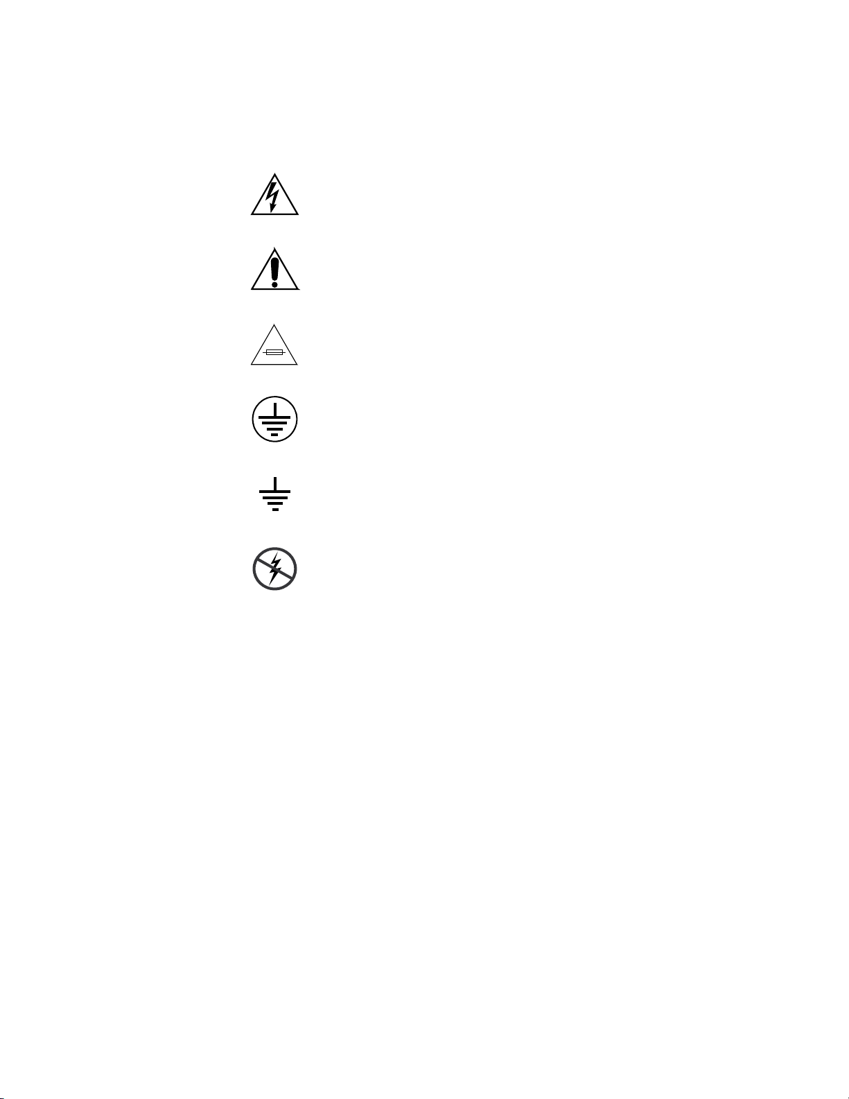
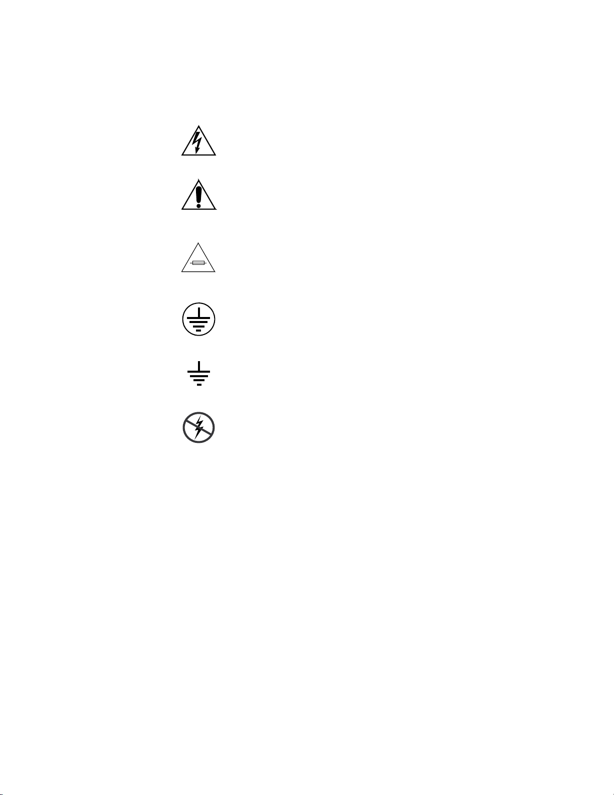
Symbols on the Product
The following symbols may appear on the product:
Indicates that dangerous high voltage is present within the
equipment enclosure that may be of sufficient magnitude to
constitute a risk of electric shock.
Indicates that user, operator or service technician should refer
to product manual(s) for important operating, maintenance,
or service instructions.
This is a prompt to note fuse rating when replacing fuse(s).
The fuse referenced in the text must be replaced with one
having the ratings indicated.
Identifies a protective grounding terminal which must be connected to earth ground prior to making any other equipment
connections.
Warnings
Identifies an external protective grounding terminal which
may be connected to earth ground as a supplement to an
internal grounding terminal.
Indicates that static sensitive components are present which
may be damaged by electrostatic discharge. Use anti-static
procedures, equipment and surfaces during servicing.
The following warning statements identify conditions or practices that can
result in personal injury or loss of life.
Dangerous voltage or current may be present — Disconnect power and remove
battery (if applicable) before removing protective panels, soldering, or
replacing components.
Do not service alone — Do not internally service this product unless another
person capable of rendering first aid and resuscitation is present.
Remove jewelry — Prior to servicing, remove jewelry such as rings, watches,
and other metallic objects.
Avoid exposed circuitry — Do not touch exposed connections, components or
circuitry when power is present.
10 Gecko Frames — Instruction Manual
Page 11

Safety Summary
Use proper power cord — Use only the power cord supplied or specified for
this product.
Ground product — Connect the grounding conductor of the power cord to
earth ground.
Operate only with covers and enclosure panels in place — Do not operate this
product when covers or enclosure panels are removed.
Use correct fuse — Use only the fuse type and rating specified for this
product.
Use only in dry environment — Do not operate in wet or damp conditions.
Use only in non-explosive environment — Do not operate this product in an
explosive atmosphere.
High leakage current may be present — Earth connection of product is essential
before connecting power.
Dual power supplies may be present — Be certain to plug each power supply
cord into a separate branch circuit employing a separate service ground.
Disconnect both power supply cords prior to servicing.
Cautions
Double pole neutral fusing — Disconnect mains power prior to servicing.
Use proper lift points — Do not use door latches to lift or move equipment.
Avoid mechanical hazards — Allow all rotating devices to come to a stop before
servicing.
The following caution statements identify conditions or practices that can
result in damage to equipment or other property
Use correct power source — Do not operate this product from a power source
that applies more than the voltage specified for the product.
Use correct voltage setting — If this product lacks auto-ranging power sup-
plies, before applying power ensure that the each power supply is set to
match the power source.
Provide proper ventilation — To prevent product overheating, provide equip-
ment ventilation in accordance with installation instructions.
Use anti-static procedures — Static sensitive components are present which
may be damaged by electrostatic discharge. Use anti-static procedures,
equipment and surfaces during servicing.
Gecko Frames — Instruction Manual 11
Page 12

Safety Summary
Do not operate with suspected equipment failure — If you suspect product damage
or equipment failure, have the equipment inspected by qualified service
personnel.
Ensure mains disconnect — If mains switch is not provided, the power cord(s)
of this equipment provide the means of disconnection. The socket outlet
must be installed near the equipment and must be easily accessible. Verify
that all mains power is disconnected before installing or removing power
supplies and/or options.
Route cable properly — Route power cords and other cables so that they ar not
likely to be damaged. Properly support heavy cable bundles to avoid connector damage.
Use correct power supply cords — Power cords for this equipment, if provided,
meet all North American electrical codes. Operation of this equipment at
voltages exceeding 130 VAC requires power supply cords which comply
with NEMA configurations. International power cords, if provided, have
the approval of the country of use.
Use correct replacement battery — This product may contain batteries. To
reduce the risk of explosion, check polarity and replace only with the same
or equivalent type recommended by manufacturer. Dispose of used batteries according to the manufacturer’s instructions.
Troubleshoot only to board level — Circuit boards in this product are densely
populated with surface mount technology (SMT) components and application specific integrated circuits (ASICS). As a result, circuit board repair at
the component level is very difficult in the field, if not impossible. For warranty compliance, do not troubleshoot systems beyond the board level.
12 Gecko Frames — Instruction Manual
Page 13

Sicherheit – Überblick
Lesen und befolgen Sie die wichtigen Sicherheitsinformationen dieses
Abschnitts. Beachten Sie insbesondere die Anweisungen bezüglich
Brand-, Stromschlag- und Verletzungsgefahren. Weitere spezifische, hier
nicht aufgeführte Warnungen finden Sie im gesamten Handbuch.
WARNUNG Alle Anweisungen in diesem Handbuch, die das Abnehmen der
Geräteabdeckung oder des Gerätegehäuses erfordern, dürfen nur von
qualifiziertem Servicepersonal ausgeführt werden. Um die
Stromschlaggefahr zu verringern, führen Sie keine Wartungsarbeiten
außer den in den Bedienungsanleitungen genannten Arbeiten aus, es sei
denn, Sie besitzen die entsprechende Qualifikationen für diese Arbeiten.
Sicherheit – Begriffe und Symbole
Safety Summary
In diesem Handbuch verwendete Begriffe
Sicherheitsrelevante Hinweise können in diesem Handbuch in der folgenden Form auftauchen:
WARNUNG Warnungen weisen auf Situationen oder Vorgehensweisen hin, die
Verletzungs- oder Lebensgefahr bergen.
VORSICHT Vorsichtshinweise weisen auf Situationen oder Vorgehensweisen hin, die zu
Schäden an Ausrüstungskomponenten oder anderen Gegenständen oder
zum zeitweisen Ausfall wichtiger Komponenten in der Arbeitsumgebung
führen können.
Hinweise am Produkt
Die folgenden Hinweise können sich am Produkt befinden:
GEFAHR – Wenn Sie diesen Begriff lesen, besteht ein unmittelbares Verlet-
zungsrisiko.
WARNUNG – Wenn Sie diesen Begriff lesen, besteht ein mittelbares Verlet-
zungsrisiko.
VORSICHT – Es besteht ein Risiko für Objekte in der Umgebung, den Mixer
selbst oder andere Ausrüstungskomponenten.
Gecko Frames — Instruction Manual 13
Page 14
Safety Summary
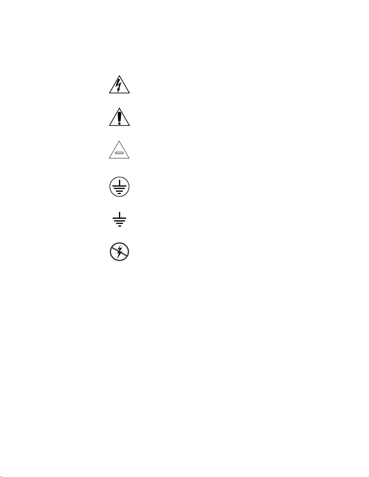
Symbole am Produkt
Die folgenden Symbole können sich am Produkt befinden:
Weist auf eine gefährliche Hochspannung im Gerätegehäuse
hin, die stark genug sein kann, um eine Stromschlaggefahr
darzustellen.
Weist darauf hin, dass der Benutzer, Bediener oder Servicetechniker wichtige Bedienungs-, Wartungs- oder Serviceanweisungen in den Produkthandbüchern lesen sollte.
Dies ist eine Aufforderung, beim Wechsel von Sicherungen
auf deren Nennwert zu achten. Die im Text angegebene Sicherung muss durch eine Sicherung ersetzt werden, die die
angegebenen Nennwerte besitzt.
Weist auf eine Schutzerdungsklemme hin, die mit dem
Erdungskontakt verbunden werden muss, bevor weitere Ausrüstungskomponenten angeschlossen werden.
Warnungen
Weist auf eine externe Schutzerdungsklemme hin, die als
Ergänzung zu einem internen Erdungskontakt an die Erde
angeschlossen werden kann.
Weist darauf hin, dass es statisch empfindliche Komponenten
gibt, die durch eine elektrostatische Entladung beschädigt
werden können. Verwenden Sie antistatische Prozeduren,
Ausrüstung und Oberflächen während der Wartung.
Die folgenden Warnungen weisen auf Bedingungen oder Vorgehensweisen
hin, die Verletzungs- oder Lebensgefahr bergen.
Gefährliche Spannungen oder Ströme – Schalten Sie den Strom ab, und entfernen
Sie ggf. die Batterie, bevor sie Schutzabdeckungen abnehmen, löten oder
Komponenten austauschen.
Servicearbeiten nicht alleine ausführen – Führen Sie interne Servicearbeiten nur
aus, wenn eine weitere Person anwesend ist, die erste Hilfe leisten und
Wiederbelebungsmaßnahmen einleiten kann.
Schmuck abnehmen – Legen Sie vor Servicearbeiten Schmuck wie Ringe,
Uhren und andere metallische Objekte ab.
14 Gecko Frames — Instruction Manual
Page 15

Safety Summary
Keine offen liegenden Leiter berühren – Berühren Sie bei eingeschalteter Strom-
zufuhr keine offen liegenden Leitungen, Komponenten oder Schaltungen.
Richtiges Netzkabel verwenden – Verwenden Sie nur das mitgelieferte Netzk-
abel oder ein Netzkabel, das den Spezifikationen für dieses Produkt
entspricht.
Gerät erden – Schließen Sie den Erdleiter des Netzkabels an den Erdungskon-
takt an.
Gerät nur mit angebrachten Abdeckungen und Gehäuseseiten betreiben – Schalten Sie
dieses Gerät nicht ein, wenn die Abdeckungen oder Gehäuseseiten entfernt
wurden.
Richtige Sicherung verwenden – Verwenden Sie nur Sicherungen, deren Typ
und Nennwert den Spezifikationen für dieses Produkt entsprechen.
Gerät nur in trockener Umgebung verwenden – Betreiben Sie das Gerät nicht in
nassen oder feuchten Umgebungen.
Gerät nur verwenden, wenn keine Explosionsgefahr besteht – Verwenden Sie dieses
Produkt nur in Umgebungen, in denen keinerlei Explosionsgefahr besteht.
Hohe Kriechströme – Das Gerät muss vor dem Einschalten unbedingt geerdet
werden.
Doppelte Spannungsversorgung kann vorhanden sein - Schließen Sie die beiden
Anschlußkabel an getrennte Stromkreise an. Vor Servicearbeiten sind beide
Anschlußkabel vom Netz zu trennen.
Zweipolige, neutrale Sicherung – Schalten Sie den Netzstrom ab, bevor Sie mit
den Servicearbeiten beginnen.
Fassen Sie das Gerät beim Transport richtig an - Halten Sie das Gerät beim Trans-
port nicht an Türen oder anderen beweglichen Teilen fest.
Gefahr durch mechanische Teile – Warten Sie, bis der Lüfter vollständig zum
Halt gekommen ist, bevor Sie mit den Servicearbeiten beginnen.
Vorsicht
Die folgenden Vorsichtshinweise weisen auf Bedingungen oder Vorgehensweisen hin, die zu Schäden an Ausrüstungskomponenten oder
anderen Gegenständen führen können.
Gerät nicht öffnen – Durch das unbefugte Öffnen wird die Garantie ungültig.
Richtige Spannungsquelle verwenden – Betreiben Sie das Gerät nicht an einer
Spannungsquelle, die eine höhere Spannung liefert als in den Spezifikationen für dieses Produkt angegeben.
Gecko Frames — Instruction Manual 15
Page 16

Safety Summary
Gerät ausreichend belüften – Um eine Überhitzung des Geräts zu vermeiden,
müssen die Ausrüstungskomponenten entsprechend den Installationsanweisungen belüftet werden. Legen Sie kein Papier unter das Gerät. Es
könnte die Belüftung behindern. Platzieren Sie das Gerät auf einer ebenen
Oberfläche.
Antistatische Vorkehrungen treffen – Es gibt statisch empfindliche Kompo-
nenten, die durch eine elektrostatische Entladung beschädigt werden
können. Verwenden Sie antistatische Prozeduren, Ausrüstung und Oberflächen während der Wartung.
CF-Karte nicht mit einem PC verwenden – Die CF-Karte ist speziell formatiert. Die
auf der CF-Karte gespeicherte Software könnte gelöscht werden.
Gerät nicht bei eventuellem Ausrüstungsfehler betreiben – Wenn Sie einen Produk-
tschaden oder Ausrüstungsfehler vermuten, lassen Sie die Komponente
von einem qualifizierten Servicetechniker untersuchen.
Kabel richtig verlegen – Verlegen Sie Netzkabel und andere Kabel so, dass Sie
nicht beschädigt werden. Stützen Sie schwere Kabelbündel ordnungsgemäß ab, damit die Anschlüsse nicht beschädigt werden.
Richtige Netzkabel verwenden – Wenn Netzkabel mitgeliefert wurden, erfüllen
diese alle nationalen elektrischen Normen. Der Betrieb dieses Geräts mit
Spannungen über 130 V AC erfordert Netzkabel, die NEMA-Konfigurationen entsprechen. Wenn internationale Netzkabel mitgeliefert wurden,
sind diese für das Verwendungsland zugelassen.
Richtige Ersatzbatterie verwenden – Dieses Gerät enthält eine Batterie. Um die
Explosionsgefahr zu verringern, prüfen Sie die Polarität und tauschen die
Batterie nur gegen eine Batterie desselben Typs oder eines gleichwertigen,
vom Hersteller empfohlenen Typs aus. Entsorgen Sie gebrauchte Batterien
entsprechend den Anweisungen des Batterieherstellers.
Das Gerät enthält keine Teile, die vom Benutzer gewartet werden können.
Wenden Sie sich bei Problemen bitte an den nächsten Händler.
16 Gecko Frames — Instruction Manual
Page 17

Consignes de sécurité
Il est recommandé de lire, de bien comprendre et surtout de respecter les
informations relatives à la sécurité qui sont exposées ci-après, notamment
les consignes destinées à prévenir les risques d’incendie, les décharges
électriques et les blessures aux personnes. Les avertissements complément
aires, qui ne sont pas nécessairement repris ci-dessous, mais présents dans
toutes les sections du manuel, sont également à prendre en considération.
AVERTISSEMENT Toutes les instructions présentes dans ce manuel qui concernent
l’ouverture des capots ou des logements de cet équipement sont
destinées exclusivement à des membres qualifiés du personnel de
maintenance. Afin de diminuer les risques de décharges
électriques, ne procédez à aucune intervention d’entretien autre
que celles contenues dans le manuel de l’utilisateur, à moins que
vous ne soyez habilité pour le faire.
Safety Summary
-
Consignes et symboles de sécurité
Termes utilisés dans ce manuel
Les consignes de sécurité présentées dans ce manuel peuvent apparaître
sous les formes suivantes
AVERTISSEMENT Les avertissements signalent des conditions ou des pratiques
susceptibles d’occasionner des blessures graves, voire même
fatales.
ATTENTION Les mises en garde signalent des conditions ou des pratiques
susceptibles d’occasionner un endommagement à l’équipement ou
aux installations, ou de rendre l’équipement temporairement non
opérationnel, ce qui peut porter préjudice à vos activités.
Signalétique apposée sur le produit
La signalétique suivante peut être apposée sur le produit :
DANGER — risque de danger imminent pour l’utilisateur.
:
AVERTISSEMENT — Risque de danger non imminent pour l’utilisateur.
MISE EN GARDE — Risque d’endommagement du produit, des installations
ou des autres équipements.
Gecko Frames — Instruction Manual 17
Page 18
Safety Summary
Symboles apposés sur le produit
Les symboles suivants peut être apposés sur le produit :
Signale la présence d’une tension élevée et dangereuse dans le
boîtier de l’équipement ; cette tension peut être suffisante
pour constituer un risque de décharge électrique.
Signale que l’utilisateur, l’opérateur ou le technicien de
maintenance doit faire référence au(x) manuel(s) pour prendre
connaissance des instructions d’utilisation, de maintenance ou
d’entretien.
Il s’agit d’une invite à prendre note du calibre du fusible lors
du remplacement de ce dernier. Le fusible auquel il est fait
référence dans le texte doit être remplacé par un fusible du
même calibre.
Identifie une borne de protection de mise à la masse qui doit
être raccordée correctement avant de procéder au
raccordement des autres équipements.
Identifie une borne de protection de mise à la masse qui peut
être connectée en tant que borne de mise à la masse
supplémentaire.
Signale la présence de composants sensibles à l’électricité
statique et qui sont susceptibles d’être endommagés par une
décharge électrostatique. Utilisez des procédures, des
équipements et des surfaces antistatiques durant les
interventions d’entretien.
18 Gecko Frames — Instruction Manual
Page 19

Avertissements
Safety Summary
Les avertissements suivants signalent des conditions ou des pratiques susceptibles d’occasionner des blessures graves, voire même fatales.
Présence possible de tensions ou de courants dangereux — Mettez hors tension,
débranchez et retirez la pile (le cas échéant) avant de déposer les couvercles
de protection, de défaire une soudure ou de remplacer des composants.
Ne procédez pas seul à une intervention d’entretien — Ne réalisez pas une interven-
tion d’entretien interne sur ce produit si une personne n’est pas présente
pour fournir les premiers soins en cas d’accident.
Retirez tous vos bijoux — Avant de procéder à une intervention d’entretien,
retirez tous vos bijoux, notamment les bagues, la montre ou tout autre objet
métallique.
Évitez tout contact avec les circuits exposés — Évitez tout contact avec les connex-
ions, les composants ou les circuits exposés s’ils sont sous tension.
Utilisez le cordon d’alimentation approprié — Utilisez exclusivement le cordon
d’alimentation fourni avec ce produit ou spécifié pour ce produit.
Raccordez le produit à la masse — Raccordez le conducteur de masse du cordon
d’alimentation à la borne de masse de la prise secteur.
Utilisez le produit lorsque les couvercles et les capots sont en place — N’utilisez pas
ce produit si les couvercles et les capots sont déposés.
Utilisez le bon fusible — Utilisez exclusivement un fusible du type et du
calibre spécifiés pour ce produit.
Utilisez ce produit exclusivement dans un environnement sec — N’utilisez pas ce
produit dans un environnement humide.
Utilisez ce produit exclusivement dans un environnement non explosible — N’utilisez
pas ce produit dans un environnement dont l’atmosphère est explosible.
Présence possible de courants de fuite — Un raccordement à la masse est indis-
pensable avant la mise sous tension.
Deux alimentations peuvent être présentes dans l’équipement — Assurez vous que
chaque cordon d’alimentation est raccordé à des circuits de terre séparés.
Débranchez les deux cordons d’alimentation avant toute intervention.
Fusion neutre bipolaire — Débranchez l’alimentation principale avant de pro-
céder à une intervention d’entretien.
Utilisez les points de levage appropriés — Ne pas utiliser les verrous de la porte
pour lever ou déplacer l’équipement.
Évitez les dangers mécaniques — Laissez le ventilateur s’arrêter avant de pro-
céder à une intervention d’entretien.
Gecko Frames — Instruction Manual 19
Page 20

Safety Summary
Mises en garde
Les mises en garde suivantes signalent les conditions et les pratiques susceptibles d’occasionner des endommagements à l’équipement et aux installations.
N’ouvrez pas l’appareil — Toute ouverture prohibée de l’appareil aura pour
effet d’annuler la garantie.
Utilisez la source d’alimentation adéquate — Ne branchez pas ce produit à une
source d’alimentation qui utilise une tension supérieure à la tension nominale spécifiée pour ce produit.
Assurez une ventilation adéquate — Pour éviter toute surchauffe du produit,
assurez une ventilation de l’équipement conformément aux instructions
d’installation. Ne déposez aucun document sous l’appareil – ils peuvent
gêner la ventilation. Placez l’appareil sur une surface plane.
Utilisez des procédures antistatiques - Les composants sensibles à l’électricité
statique présents dans l’équipement sont susceptibles d’être endommagés
par une décharge électrostatique. Utilisez des procédures, des équipements
et des surfaces antistatiques durant les interventions d’entretien.
N’utilisez pas la carte CF avec un PC — La carte CF a été spécialement formatée.
Le logiciel enregistré sur la carte CF risque d’être effacé.
N’utilisez pas l’équipement si un dysfonctionnement est suspecté — Si vous sus-
pectez un dysfonctionnement du produit, faites inspecter celui-ci par un
membre qualifié du personnel d’entretien.
Acheminez les câbles correctement — Acheminez les câbles d’alimentation et les
autres câbles de manière à ce qu’ils ne risquent pas d’être endommagés.
Supportez correctement les enroulements de câbles afin de ne pas endommager les connecteurs.
Utilisez les cordons d’alimentation adéquats — Les cordons d’alimentation de cet
équipement, s’ils sont fournis, satisfont aux exigences de toutes les réglementations régionales. L’utilisation de cet équipement à des tensions dépassant les 130 V en c.a. requiert des cordons d’alimentation qui satisfont aux
exigences des configurations NEMA. Les cordons internationaux, s’ils sont
fournis, ont reçu l’approbation du pays dans lequel l’équipement est utilisé.
Utilisez une pile de remplacement adéquate — Ce produit renferme une pile. Pour
réduire le risque d’explosion, vérifiez la polarité et ne remplacez la pile que
par une pile du même type, recommandée par le fabricant. Mettez les piles
usagées au rebut conformément aux instructions du fabricant des piles.
Cette unité ne contient aucune partie qui peut faire l’objet d’un entretien
par l’utilisateur. Si un problème survient, veuillez contacter votre distributeur local.
20 Gecko Frames — Instruction Manual
Page 21

Regulatory Notices
Certifications and Compliances
FCC Emission Control
This equipment has been tested and found to comply with the limits for a
Class A digital device, pursuant to Part 15 of the FCC Rules. These limits
are designed to provide reasonable protection against harmful interference
when the equipment is operated in a commercial environment. This equip
ment generates, uses, and can radiate radio frequency energy and, if not
installed and used in accordance with the instruction manual, may cause
harmful interference to radio communications. Operation of this equip
ment in a residential area is likely to cause harmful interference in which
case the user will be required to correct the interference at his own expense.
Changes or modifications not expressly approved by Grass Valley Group
can affect emission compliance and could void the user’s authority to
operate this equipment.
-
-
Canadian EMC Notice of Compliance
This digital apparatus does not exceed the Class A limits for radio noise
emissions from digital apparatus set out in the Radio Interference Regula
tions of the Canadian Department of Communications.
Le présent appareil numérique n’emet pas de bruits radioélectriques
dépassant les limites applicables aux appareils numeriques de la classe A
préscrites dans le Règlement sur le brouillage radioélectrique édicte par le
ministère des Communications du Canada.
EN55022 Class A Warning
In a domestic environment, products that comply with Class A may cause
radio interference in which case the user may be required to take adequate
measures.
-
Gecko Frames — Instruction Manual 21
Page 22

Regulatory Notices
Canadian Certified Power Cords
Canadian Certified AC Adapter
Laser Compliance
Laser Safety Requirements
Canadian approval includes the products and power cords appropriate for
use in the North America power network. All other power cords supplied
are approved for the country of use.
Canadian approval includes the AC adapters appropriate for use in the
North America power network. All other AC adapters supplied are
approved for the country of use.
The device used in this product is a Class 1 certified laser product. Operating this product outside specifications or altering from its original design
may result in hazardous radiation exposure, and may be considered an act
of modifying or new manufacturing of a laser product under U.S. regula
tions contained in 21CFR Chapter 1, subchapter J or CENELEC regulations
in HD 482 S1. People performing such an act are required by law to recertify
and reidentify this product in accordance with provisions of 21CFR sub
chapter J for distribution within the U.S.A., and in accordance with
CENELEC HD 482 S1 for distribution within countries using the IEC 825
standard.
-
-
Laser Safety
Laser safety in the United States is regulated by the Center for Devices and
Radiological Health (CDRH). The laser safety regulations are published in
the “Laser Product Performance Standard,” Code of Federal Regulation
(CFR), Title 21, Subchapter J.
The International Electrotechnical Commission (IEC) Standard 825, “Radiation of Laser Products, Equipment Classification, Requirements and
User’s Guide,” governs laser products outside the United States. Europe
and member nations of the European Free Trade Association fall under the
jurisdiction of the Comite European de Normalization Electrotechnique
(CENELEC).
For the CDRH: The radiant power is detected through a 7 mm aperture at
a distance of 200 mm from the source focused through a lens with a focal
length of 100 mm.
For IEC compliance: The radiant power is detected through a 7 mm aperture at a distance of 100 mm from the source focused through a lens with a
focal length of 100 mm.
22 Gecko Frames — Instruction Manual
Page 23

FCC Emission Limits
Certification
Regulatory Notices
This device complies with Part 15 of the FCC Rules. Operation is subject to
the following two conditions: (1) This device may not cause harmful inter
ference, and (2) this device must accept any interference received,
including interference that may cause undesirable operation. This device
has been tested and found to comply with FCC Part 15 Class B limits for a
digital device when tested with a representative laser-based fiber optical
system that complies with ANSI X3T11 Fiber Channel Standard.
Category Standard Designed/tested for compliance with:
Safety ANSI/UL60950 Safety of Information Technology Equipment, including Electrical Busi-
ness Equipment (Third edition, 2000).
IEC 60950 Safety of Information Technology Equipment, including Electrical Busi-
ness Equipment (Third edition, 1999).
CAN/CSA C22.2, No. 60950-00Safety of Information Technology Equipment, including Electrical Busi-
ness Equipment.
BSEN60950 Safety of Information Technology Equipment, including Electrical Busi-
ness Equipment.
-
Gecko Frames — Instruction Manual 23
Page 24

Regulatory Notices
24 Gecko Frames — Instruction Manual
Page 25

Gecko 8900 Series Frames
Introduction
The Grass Valley Gecko™ 8900 Signal Processing System is a family of conversion, distribution, timing, and processing modules which provides
support for a wide variety of signal processing applications.
Two Gecko 8900 Series frame types are available to support these modules:
• 8900 BNC/Video – providing BNC input/output connectors for video
modules, and
• 8900 Balanced Audio – providing four BNC connectors and 10 three terminal audio connectors for balanced input/output connections for
audio modules.
Section 1
Note Refer to the documentation for each 8900 module for frame compatibility
information.
Key features of the Gecko 8900 Series frames include:
• Support of all Grass Valley 8900 Series modules,
• Wide range of analog and digital functions,
• 10 module slots in each 2 RU frame,
• Analog/digital passive loop-through inputs,
• 100 W power supplies, each with independent AC main inputs and
integrated cord retention,
• LEDs on front cover for fault and power supply status,
• Self-contained variable speed cooling,
• Ethernet control and monitoring,
• Serial interface for IP Address configuration and Frame Alarm output,
and
• IP network identity stored in non-volatile frame memory.
The power usage of 8900 modules varies greatly from less complex analog
to higher complexity digital modules. To handle these power requirements
Gecko Frames — Instruction Manual 25
Page 26

Section 1 — Gecko 8900 Series Frames
and offer more control and monitoring flexibility, both frame types are
offered in 8900TX, TF, and TFN models.
These models provide:
• 8900TX-V/TX-A – Vented cover for passive cooling and single 100 W
power supply for modules outputting up to 30 W power,
• 8900TF-V/TF-A – Fan front cover with a variable fan speed mode and
a single 100 W power supply, and
• 8900TFN-V/TFN-A – Fan front cover, 100W power supply, and
Ethernet capability for remote control and monitoring using a webbased GUI (Graphical User Interface) with the 8900NET Network Interface Module.
An 8900 Video frame can house 8900 Series video modules and Grass
Valley 8500 or 8800 analog distribution amplifiers (except the 8510R). The
frame can house from one to ten 8900 video modules depending upon
power requirements.
The 8900 Audio frame offers the same power, cooling, and control options
as the 8900 Video frame while providing a backplane with three-terminal
connectors for balanced audio inputs and outputs. Each audio module slot
provides 10 three-terminal connectors and four BNC connectors for functions determined by the specific audio module installed.
Frame Options and Upgrades
Ta bl e 1 shows the Gecko 8900 Series frame models available. Tab le 2 pro-
vides the upgrade options available to extend the frame capabilities.
Table 1. Frame Models and Features
Model # Cover type/power max. Controller Active Comm. Ports
8900TX-V/TX-A Convection/30 Watts None None
8900TF-V/TF-A Fan Front Cover/100 Watts Frame Monitor Module Frame Alarm
8900TFN-V/TFN-A Fan Front Cover/100 Watts 8900NET Network Interface Module Frame Alarm, RS-232, Ethernet
Table 2. Frame Upgrade Options and Features for Both Video and Audio Frames
Model # Upgrade Cover type/power max. Controller Active Comm. Ports
8900FAN 8900TX to 8900TF Fan/100 Watts Frame Monitor Module Frame Alarm
8900FN 8900TX to 8900TFN Fan/100 Watts 8900NET Network Interface Module Frame Alarm, RS-232, Ethernet
8900NET 8900TF to 8900TFN Fan/100 Watts 8900NET Network Interface Module Frame Alarm, RS-232, Ethernet
26 Gecko Frames — Instruction Manual
Page 27

8900TX Convection System
PS 1 PS 2
LOCK
LOCK
0636-06
Power Indicator LEDs
The convection system consists of the following:
• 8900TX-V/TX-A, convection frame, and one power supply
• 8900PSX, redundant power supply (optional)
The convection frame has a vented front cover and filter for convective air
flow. This frame is used primarily for analog and a limited quantity of
digital modules with a total power requirement less than 30 watts. Refer to
Frame Cooling on page 31.
The convection frame is illustrated in Figure 1.
Figure 1. Convection Frame
8900TX Convection System
Note A convection frame can be upgraded to a forced-air or a networked frame.
This requires the use of model 8900FAN retrofit kit which provides fans and
the Fault indication window in the cover (see Figure 2 on page 14) and the
8900NET for networking capability.
Gecko Frames — Instruction Manual 27
Page 28

Section 1 — Gecko 8900 Series Frames
PS 1 PS 2
LOCK
LOCK
FAULT
0636-07
Fault Condition Indicator LED Power Indicator LEDs
8900TF Forced-air System
The forced-air system (Figure 2) consists of the following:
• 8900TF-V/TF-A, forced-air frame, Frame Monitor module, and one
power supply
• 8900PSX, 100 W redundant power supply (optional)
The forced-air system has a front cover that is equipped with three fans for
air circulation. The fan speed varies with the ambient frame temperature to
extend fan life and reduce noise when the frame is used in cooler configurations and environments. The fan speed control voltage is generated on
the Frame Monitor module and can be disabled so that the fan runs at
maximum speed only. This frame is recommended for power requirements
greater than 30 watts or when Frame alarm reporting (via the Frame
Monitor module) is required. Refer to Frame Cooling on page 31.
Note A forced-air TF-V or TF-A frame can be converted to a networked TFN-V or
TFN-A frame with the 8900NET option.
Figure 2. Forced-air or Networked Frame
8900TFN Networked System
The networked system consists of the following:
• 8900TFN-V/TFN-A, forced-air frame, 8900NET Network Interface
Module, and one power supply
• 8900PSX, 100 W redundant power supply (optional)
The networked system has the same features as the forced-air system
including the fan cover (Figure 2) and fault and power indicators. Also
included is the 8900NET Network Interface module allowing the frame to
communicate over an Ethernet LAN to the web browser GUI interface for
remote control of 8900 modules.
28 Gecko Frames — Instruction Manual
Page 29

Frame Connections
J1 J2
J3 J4
J5 J6
J7 J8
J9 J10
IN
DA1
J2
J4
J6
J8
J1 J2
J3 J4
J5 J6
J7 J8
J9 J10
IN
DA3
J1 J2
J3 J4
J5 J6
J7 J8
J9 J10
IN
DA5
J1 J2
J3 J4
J5 J6
J7 J8
J9 J10
IN
DA2
J1 J2
J3 J4
J5 J6
J7 J8
J9 J10
IN
DA7
J1 J2
J3 J4
J5 J6
J7 J8
J9 J10
IN
DA9
J1 J2
J3 J4
J5 J6
J7 J8
J9 J10
IN
DA4
J2
J4
J6
J8
J1 J2
J3 J4
J5 J6
J7 J8
J9 J10
IN
DA6
J2
J4
J6
J8
J1 J2
J3 J4
J5 J6
J7 J8
J9 J10
IN
DA8
J2
J4
J6
J8
J1 J2
J3 J4
J5 J6
J7 J8
J9 J10
IN
DA10
O
U
T
O
U
T
O
U
T
O
U
T
O
U
T
O
U
T
O
U
T
O
U
T
O
U
T
O
U
T
0636 -03
0636 -17
J1
J3
J5
J7
J9
J2
J4
J6
J8
J10
J11
J13
J12
J14
IN
1
J1
J3
J5
J7
J9
J2
J4
J6
J8
J10
J11
J13
J12
J14
IN
2
J1
J3
J5
J7
J9
J2
J4
J6
J8
J10
J11
J13
J12
J14
IN
3
J1
J3
J5
J7
J9
J2
J4
J6
J8
J10
J11
J13
J12
J14
IN
4
J1
J3
J5
J7
J9
J2
J4
J6
J8
J10
J11
J13
J12
J14
IN
5
J1
J3
J5
J7
J9
J2
J4
J6
J8
J10
J11
J13
J12
J14
IN
6
J1
J3
J5
J7
J9
J2
J4
J6
J8
J10
J11
J13
J12
J14
IN
7
J1
J3
J5
J7
J9
J2
J4
J6
J8
J10
J11
J13
J12
J14
IN
8
J1
J3
J5
J7
J9
J2
J4
J6
J8
J10
J11
J13
J12
J14
IN
9
J1
J3
J5
J7
J9
J2
J4
J6
J8
J10
J11
J13
J12
J14
IN
10
Two types of connector backplanes are available in the Gecko 8900 Series
frames. The 8900 BNC/Video frame provides ten module slots, each with a
loop-through input and up to eight connectors for input/output functions
as needed for a specific module type (
Figure 3. 8900 Video Frame Module I/O Connectors
The 8900 Balanced Audio frame provides 10 three-terminal connectors and
4 BNC connectors (Figure 4). As in the Video frame, two of the BNCs are for
loop-through connection.
Frame Connections
Figure 3).
Figure 4. 8900 Audio Frame Module I/O Connectors
Gecko Frames — Instruction Manual 29
Page 30

Section 1 — Gecko 8900 Series Frames
The power/communication backplane section of the frame (Figure 5 and
Figure 6) provides:
• AC power plug connections
• DB-9 connector labeled RS-232 (requires the 8900NET module) with
Frame Alarm connections (pins 8 and 9 of RS-232 connector)
• Ethernet RJ-45 connector (requires the 8900NET module)
The RS-232 port provides connection to a PC used for initial network configuration. Pins 8 and 9 of the RS-232 port can be used for Frame Alarm
reporting. The RJ-45 Ethernet connector provides a 10Base-T Ethernet
network connection with the 8900NET Network Interface module.
Figure 5. Power/Communication Connectors on 8900 Video/BNC Frames
RS232
Frame Alarm
J102 pins 8 and 9
J102
U2
J1 J2
ETHERNET
J103
0636 -23
U1
Figure 6. Power/Communication Connectors on 8900 Balanced Audio Frames
Frame Alarm
J7 pins 8 and 9
0636 -18
U1
J1
RS232
J7
J2
ETHERNET
J10
30 Gecko Frames — Instruction Manual
Page 31

Network Configuration Storage
Frame Cooling
Frame Cooling
Both the 8900 BNC/Video and Balanced Audio frames are equipped with
IP address storage capability on the rear backplane. When an 8900NET
module is installed (with version 3.0 software or later), the IP address
assignments made on the 8900NET module for network configuration are
stored on the frame. The current network configuration information will
then stay with the frame if the 8900NET module is moved.
Note Older version 8900 frames do not have IP address storage capability. IP
address information is stored only on the 8900NET module. Refer to Video
Frame on page 58 for more information.
The convection frame and the forced-air frame provide a great deal of flexibility in the type of modules that can be installed. Conventional low power
analog DAs can be used alongside higher power serial digital modules
with all modules performing to their full specifications.
For installations that require only low power modules or modules that
have a combined total dissipation of less than 30 watts, the convection
frame will provide adequate cooling.
Note The 30 watt TX-A/-V frame is best used for modules with less than 5.5 watts
power dissipation. When total power dissipation approaches maximum,
provide as much space as possible between the modules.
For installations where the modules dissipate greater than 30 watts, a
forced air frame must be used.
CAUTION Do not leave a fan front cover off of an air-cooled frame for extended periods.
For reliable operation, the forced-air cover should not be removed for longer
than five minutes when cooling more that 30 watts.
Gecko Frames — Instruction Manual 31
Page 32

Section 1 — Gecko 8900 Series Frames
Calculating Frame Power
To calculate the power required for your frame, you must total all the
power dissipated for each individual module.
Table 3 provides the power dissipation for many of the modules compat-
ible with the 8900 Video and Audio frames. For newer modules not listed,
refer to the Specifications table in the specific module instruction manual.
Table 3. Module Power Dissipation
Module Power Dissipation Module Power Dissipation
All 8500 Modules 2 Watts 8920Mux 7 Watts
All 8800 Modules 2 Watts 8931 2 Watts
8910ADA-M/ST 3 Watts 8936 3 Watts
8910ADA-SR 5 Watts 8941 6 Watts
8911 3 Watts 8942 5 Watts
8912RDA/-D 4 Watts 8950ADC 7.2 Watts
8914 3.5 Watts 8950DAC 7.5 Watts
8916 6 Watts 8960DEC
8920ADC 4.2 Watts 8960ENC
8920ADT 6 Watts 8981FS 4.5 Watts
8920DAC 3.1 Watts 8990ARC 6.5 Watts
8920DMX 7 Watts
6.5 Watts, 8.5 Watts with
Frame Sync option
6.5 Watts, 8.5 Watts with
Frame Sync option
Two examples of power calculations are shown in Tabl e 4 and Table 5.
Table 4. Module Power Dissipation, example 1
Module Quantity
8800 5 2 Watts 10 Watts
8960DEC
without Frame Sync
8936 2 3 Watts 6 Watts
Total Frame Power
2 6.5 Watts 13 Watts
Power Per
Module
Total Power
29 Watts
The total frame power required is less than 30 watts; therefore, the convection frame may be used.
Table 5. Module Power Dissipation, example 2
Module Quantity
8836 1 3 Watts 3 Watts
8916 2 6 Watts 12 Watts
8960DEC
without Frame Sync
3 6.5 19.5
Power Per
Module
Total Power
32 Gecko Frames — Instruction Manual
Page 33

Frame Monitor and Network Interface Modules
Table 5. Module Power Dissipation, example 2
Module Quantity
8941 4 6 Watts 24 Watts
Total Frame Power
With ten modules, the total frame power required is greater than 30 watts
and an 8900TF or 8900TFN forced-air frame must be used.
Power Per
Module
Tot al Power
58.5 Watts
Frame Monitor and Network Interface Modules
8900 frame configuration supports the use of either the Frame Monitor or
the 8900NET Network Interface module. The Frame Monitor module pro
vides alarm reporting for the Frame Alarm only. The 8900NET Network
Interface module provides full functionality of the frame communication
buses including:
•Frame Alarm,
-
• RS-232 Configuration, and
• 10Base-T Ethernet.
Refer to the 8900NET Network Interface Module Instruction Manual.
Gecko Frames — Instruction Manual 33
Page 34

Section 1 — Gecko 8900 Series Frames
34 Gecko Frames — Instruction Manual
Page 35

Installation
0636 -13
Ejector
tab
lock pin
Introduction
This section contains information about:
• Rack mounting the frame,
• Module and Power Supply installation,
• Rear connectors, and
•Frame Alarm.
Rack Mounting the Frame
Section 2
After carefully unpacking this equipment, check the box for a power cords
and other hardware, and examine the equipment for damage. Any damage
should be promptly reported to the carrier.
The frame is designed to mount in a standard 19-inch equipment rack.
Mounting space of 3.5 inches (89 mm) vertically and mounting depth of 14
inches (356 mm) are required. Mount the frame in a standard 19-inch rack
using customer-supplied rack mounting screws.
CAUTION Before lifting the frame, verify that the power supplies are fully seated in their
slots. Front ejector tabs should click into place when snapped on the locking
pin on the module (see Figure 7).
Figure 7. Power Supply Ejector Tab Locking Pin
Gecko Frames — Instruction Manual 35
Page 36

Section 2 — Installation
Any 8900 Module
Gecko
Power
Supplies
Only
0636-04r3
Frame Monitor or
8900NET Network
Interface Module
Module and Power Supply Installation
Module Installation
There are ten cell locations in each frame to accommodate either video or
audio modules (module types cannot be mixed in a frame). These are the
ten cells located on the left side of the frame. Refer to
Modules can be configured for up to eight outputs. The 8500 modules have
six outputs. The 8800 and 8900 modules have eight outputs. Refer to individual module manuals for input/output configuration information.
The two cells on the right are allocated for the power supplies only. The
third cell from the right, is allocated only for the Frame Monitor or
8900NET Network Interface module. This module provides the interface
for the forced-air cover, as well as the Frame Alarm reporting. For additional information concerning the Frame Monitor and Network Interface
modules, refer to Section 4-Monitoring and Control.
Figure 8.
Figure 8. Gecko 8900 Series Frame
To install a module into the frame, follow these steps:
1. Insert the module into the frame, connector-end first, with component
side of the module facing to the right with the ejector tab at the top. The
Frame Monitor and the 8900NET module have a connector tab with a
circular finger-hole for pulling the module rather than an ejector tab.
The connector tab should be oriented in the top half of the frame.
2. Verify that the module connector seats properly against the backplane.
3. Press the ejector tab or connector tab in to seat the module in place.
36 Gecko Frames — Instruction Manual
Page 37

Power Supply Installation
Gecko 100 Watt Power Supply
0636_25
Protective cover
The frame will come with a single Gecko 100 Watt power supply installed
in one of the slots on the far right. The currently shipping 100W Gecko
Frame power supply with a proctective front cover is similar to the one
shown in
If you have ordered a redundant power supply, install it in the empty cell
on the far right of the frame (see the location drawing in Figure 8 on
page 36), making sure the ejector tab locks into place.
Note Power supplies used in the 8900 Gecko frames (8900TF/TFN-A/-V) and the
Figure 9. Power Supply Installation
Figure 9.
ones used in the GeckoFlex frames cannot be swapped. They are different
lengths.
Module and Power Supply Installation
Gecko Frames — Instruction Manual 37
Page 38

Section 2 — Installation
J1 J2
J3 J4
J5 J6
J7 J8
J9 J10
IN
DA1
J2
J4
J6
J8
J1 J2
J3 J4
J5 J6
J7 J8
J9 J10
IN
DA3
J1 J2
J3 J4
J5 J6
J7 J8
J9 J10
IN
DA5
J1 J2
J3 J4
J5 J6
J7 J8
J9 J10
IN
DA2
J1 J2
J3 J4
J5 J6
J7 J8
J9 J10
IN
DA7
J1 J2
J3 J4
J5 J6
J7 J8
J9 J10
IN
DA9
J1 J2
J3 J4
J5 J6
J7 J8
J9 J10
IN
DA4
J2
J4
J6
J8
J1 J2
J3 J4
J5 J6
J7 J8
J9 J10
IN
DA6
J2
J4
J6
J8
J1 J2
J3 J4
J5 J6
J7 J8
J9 J10
IN
DA8
J2
J4
J6
J8
J1 J2
J3 J4
J5 J6
J7 J8
J9 J10
IN
DA10
O
U
T
O
U
T
O
U
T
O
U
T
O
U
T
O
U
T
O
U
T
O
U
T
O
U
T
O
U
T
0636 -03
0636 -17
J1
J3
J5
J7
J9
J2
J4
J6
J8
J10
J11
J13
J12
J14
IN
1
J1
J3
J5
J7
J9
J2
J4
J6
J8
J10
J11
J13
J12
J14
IN
2
J1
J3
J5
J7
J9
J2
J4
J6
J8
J10
J11
J13
J12
J14
IN
3
J1
J3
J5
J7
J9
J2
J4
J6
J8
J10
J11
J13
J12
J14
IN
4
J1
J3
J5
J7
J9
J2
J4
J6
J8
J10
J11
J13
J12
J14
IN
5
J1
J3
J5
J7
J9
J2
J4
J6
J8
J10
J11
J13
J12
J14
IN
6
J1
J3
J5
J7
J9
J2
J4
J6
J8
J10
J11
J13
J12
J14
IN
7
J1
J3
J5
J7
J9
J2
J4
J6
J8
J10
J11
J13
J12
J14
IN
8
J1
J3
J5
J7
J9
J2
J4
J6
J8
J10
J11
J13
J12
J14
IN
9
J1
J3
J5
J7
J9
J2
J4
J6
J8
J10
J11
J13
J12
J14
IN
10
Rear Connectors
Modules may be configured for a variety of inputs and outputs. The 8500
modules have six outputs. The 8800 and 8900 modules have up to eight out
puts. Refer to individual module manuals for specific configuration information.
Note Connector configuration overlays are available for many 8900 modules that
Figure 10 illustrates the rear backplane of the 8900 BNC/Video frame.
Figure 10. 8900 Series Rear Connector Plate
-
do not use the standard DA configuration (one looping input and eight BNC
outputs). These overlays are found at the back of the module Instruction
Manual.
Figure 11 illustrates the 8900 Balanced Audio Frame three-terminal and
BNC connectors on the rear backplane.
Figure 11. 8900 Series Audio Frame Rear Connector Plate
The rear connector backplane will be discussed in the following order:
• Loop-through Input
• Direct Input/Output Connectors
• Frame Alarm Connection
38 Gecko Frames — Instruction Manual
Page 39

Loop-through Input Connectors
Input signals are routed through the rear of the frame. There is one loopthrough input for each module cell refer to
page 38.
Note No more than five digital modules should be looped. Use cables less than
two meters in length, and an input cable of less than 200 meters of Belden
8281 (or equivalent).
If not used for looping, the unused loop-through connector must be externally terminated. The recommended termination for serial digital signals is
CONARE BCP-TA (or equivalent).
Performance of looping inputs to equipment other than 8900 modules has
not been verified; monitor signal quality carefully when configuring such a
system.
Serial digital video is a wideband RF signal. Be sure to protect the data from
environmental noise. The serial digital signal is attenuated by as much as
30 dB after traveling through 1000 feet of 8281 cable. An equalizer must be
used to restore the signal so data can be recovered. The equalizer boosts the
serial digital video signal and any environmental noise on the line. Data
corruption takes place if the environmental noise is large enough to cause
pick-off errors in the equalizer.
Rear Connectors
Figure 10 and Figure 11 on
When connecting serial digital video signals to and from the 8900 Series
frame:
• Use high quality BNC connectors to ensure continuous shield connections.
• Use high quality cable (8281 or 1694A).
• Use one continuous cable for long cable runs. Avoid using patch panels
or BNC barrel connectors.
Note These recommendations become even more important in noisy environ-
ments (subject to radio frequencies and static) with long cable runs.
Direct Input/Output Connectors
In the video frame (refer to Figure 12) there are eight direct (not looping)
input/output BNC connectors provided for each module slot (J1 – J8).
Refer to the Instruction Manual for the specific module for input/output
connector information.
Note If 8500 modules are used in the frame, there are six outputs provided for each
module, J1 through J6.
Gecko Frames — Instruction Manual 39
Page 40

Section 2 — Installation
J2
J4
J6
J8
J9
J10
IN
10
O
U
T
J3
J5
J7
J2
J1
J4
J6
J8
Slot Number (1-10)
Video Frame
Connectors
0636-02r1
J2
J1
J3
J5
J7
J9
J2
J4
J6
J8
J10
J11
J13
J12
J14
IN
1
Wiring for
Audio Connector
(top view)
+ - G
0636_24
+ - G
Cable Tie
Audio
Cable
Figure 12. Video Frame Rear Input and Output Connector Labeling
The audio frame provides two direct input/output BNCs (J11 and J12), two
looping BNCs (J13 and J14), and ten three-terminal input/output connectors (J1 – J10) shown in Figure 13. A pack of 100 audio connectors is provided with the frame for connecting audio cable to the rear connectors.
Refer to the specific audio module Instruction Manual for cabling information. Pinout information for each module may also be silkscreened on the
module circuit board.
Figure 13. Audio Frame Rear Input and Output Connector Labeling
40 Gecko Frames — Instruction Manual
Page 41

Frame Alarm Connector
Pin 5
Pin 6
Pin 9
D-9 Female
Pin 1
Use of the Frame Alarm requires the presence of either the Frame Monitor
or 8900NET Network Interface module in the frame. Frame Monitor
module features are discussed in
manual. For information on the 8900NET module see the 8900 Network
Interface Module Instruction Manual.
The Frame Alarm is accessed through pins 8 and 9 of the RS-232 DB-9 connector (Video Frame – J102, Audio Frame – J7) as shown in Figure 14. Refer
to Frame Alarm Example on page 43 for using the port in an alarm circuit.
Note Earlier model 8900 frames had a SMPTE ALARM BNC for accessing the
Frame Alarm output. Refer to SMPTE Alarm Connector on page 58 for cabling
information on older frames.
Figure 14. Frame Alarm Connector Location
RS232
Rear Connectors
Section 4-Monitoring and Control in this
Frame Alarm
(Video – J102 pins 8 and 9)
(Audio – J7 pins 8 and 9)
J1 J2
ETHERNET
0636 -20r0
The pinout for the RS-232 DB-9F connector is given in Table 6.
Table 6. RS-232 Connector Pinouts
Frame
RS-232 Port
Video Frame – J102
Pin
Audio Frame – J7
1N/C
2TX
3RX
4N/C
5Gnd
6N/C
7N/C
8Frame Alarm
9Frame Alarm
Gecko Frames — Instruction Manual 41
Page 42

Section 2 — Installation
Frame Alarm Conditions
The conditions monitored by Frame Alarm reporting are:
•Frame Health
• Power supply 1 voltage
• Power supply 2 voltage
•Fan rotation
• Frame temperature
• Module Health Bus (8900 Video Frames only)
• Power supply voltage
• Signal present at input
•EQ warning
The Module Health bus provides a means for older (legacy) or less capable
modules (such as DAs with no microprocessor) that cannot communicate
over the Frame serial bus to report alarm conditions to the Frame Monitor
or 8900NET module. The reporting is done using a voltage level sent by the
module to the Frame Alarm connector. When a problem exists on the
module, the Module Health bus will indicate that a problem exists on the
module but will not indicate what the problem is.
Alarm conditions are enabled or disabled by using the Alarm Reporting
DIP switch(es) on either the Frame Monitor or 8900NET modules. Refer to
Enabling Alarms and Fan Speed Control Option on page 51 for the Frame
Monitor module. For information on setting the 8900NET switches, refer to
the 8900 Network Interface Module Instruction Manual.
In addition to fault reporting through the Frame Alarm connector, there is
a red Fault LED on the 8900TF/TFN front cover. This LED is off when no
fault conditions are detected and on when either an internal fault or a signal
error is detected.
42 Gecko Frames — Instruction Manual
Page 43

Frame Alarm Example
+5V
4.7 kΩ
4.7 kΩ
330 Ω
470 Ω
Alarm
LED
2N4126
(or equivalent)
RS-232 Pin 8
RS-232 Pin 9
Refer to Figure 15 for an example of a typical alarm schematic using pins 8
and 9 of the RS-232 port.
Figure 15. Typical Alarm Schematic for Frame Alarm
The impedance between the pins 8 and 9 of the RS-232 connector can be in
one of two states:
Rear Connectors
• Open – less than 100 μA of current will flow with 5 volts across the pins,
and
• Closed – less than 0.2 V will appear from pin 8 to pin 9 with 20 mA of
current flowing.
There are three operational conditions (capability is module dependent,
refer to specific module instruction manual):
•Open – no faults,
• Closed – there is an internal fault, and
• Pulsing – there is a missing or invalid signal on one or more of the modules.
Gecko Frames — Instruction Manual 43
Page 44

Section 2 — Installation
44 Gecko Frames — Instruction Manual
Page 45

Power Up
0636 -13
Ejector
tab
lock pin
Introduction
This section contains information about:
• Power Connections
• Applying Power
CAUTION Verify that the power supplies are fully seated in their slots. Ejector tabs
Section 3
should click into place when snapped on the locking pin on the module (see
Figure 16).
Figure 16. Power Supply Ejector Tab Locking Pin
Gecko Frames — Instruction Manual 45
Page 46

Section 3 — Power Up
0636 -05r1
J1
J2
RS232
ETHERNET
Power Connections
There are two types of power cords supplied with the 8900 Series frames
for 120 V and 240 V operation. Line voltage selection is not required for this
power supply. Optional redundant power supplies are also shipped with
both types of power cord.
120 VAC
This cord has a molded grounding plug at one end and a molded grounded
receptacle at the other end. Conductors are color-coded white (neutral),
black (line), and green or green/yellow (ground).
240 VAC
This cord has a molded grounding receptacle at one end and stripped conductors at the other end. Conductors are color-coded light blue (neutral),
brown (line), and green/yellow (ground).
For each power supply installed, AC power is fed through a line cord to a
socket (J1 and J2) on the rear of the frame (Figure 17).
Figure 17. AC Power Connectors
Note To maintain maximum redundant power, ensure that each power supply cord
is plugged into a separate branch circuit.
46 Gecko Frames — Instruction Manual
Page 47

Line Cord Retainer
Retention Clip
0636 -08
To help prevent accidental loss of power, the AC line cord is held in place
by a retainer clip (
Figure 18. Cable Retainer Clip
To properly install the line cord, follow these steps:
Power Connections
Figure 18).
1. Ensure that the retainer clip is inserted properly into the holes of the
screw caps.
2. Rotate the retainer clip sideways, and plug the power cord into the
receptacle.
3. Rotate the retainer clip back onto the plug body to hold the power cord
in place.
Gecko Frames — Instruction Manual 47
Page 48

Section 3 — Power Up
LOCK
0636-15
Power Indicator LEDs
Fault LED
PS 1 PS 2FAULT
Applying Power
Upon applying power to the frame, verify that the green power LED for
each power supply (assuming a redundant supply is present)PS1 and PS2
is illuminated (
check the red FAULT LED. It should be off if the fans are operating correctly.
Figure 19. Power Indicator LEDs (TF frame shown)
Figure 19). If the frame is a TF or TFN model (with fans),
Other indicator LEDs can be viewed on the controller module (Frame
Monitor or 8900NET module) with the front cover removed. Frame
Monitor module indicators are discussed in Section 4-Monitoring and Con-
trol. If you have a 8900NET module installed in the frame, see the 8900NET
Network Interface Module Instruction Manual for indicator details.
48 Gecko Frames — Instruction Manual
Page 49

Monitoring and Control
Introduction
The Gecko 8900TF/8900TFN frames offer monitoring and remote control
capability by providing two types of frame communication modules that
can reside in the controller cell of the frame:
• Frame Monitor module (8900TF Frame), or
• 8900NET Network Interface module (8900TFN Frame).
The 8900NET Network Interface module supports all the functionality of
the Frame Monitor module plus the 10 Base-T Ethernet bus for web-based
GUI control and monitoring. For information on the 8900NET module and
GUI refer to the 8900NET Network Interface Module Instruction Manual.
Section 4
The Frame Monitor module is described in this manual. The Frame
Monitor module is an interface for the forced-air cover and Frame Alarm
fault reporting.
The Frame Monitor module provides:
• Variable power to the fan front cover to regulate fan speed
• Analog module presence indication
• LED display for quick diagnostics of alarm conditions
• DIP switch for enabling and disabling alarms and the variable fan
speed option
Gecko Frames — Instruction Manual 49
Page 50

Section 4 — Monitoring and Control
Frame Monitor Module
The Frame Monitor module comes installed in the 8900TF frame. It provides indicator LEDs on the front of the module (visible when fan front
cover is removed) that report alarm conditions and module power status.
When on, the LEDs indicate:
• TEMP — Over-temperature problem
• PS2 — Power supply position 2 health problem
• PS1 — Power supply position 1 health problem
• FAN — Cooling fan is not rotating
• MOD — Module health bus error
•INHIB — Disabled module health bus
• FAULT — Reports that one or more of the above alarm conditions is
present and the other Fault LEDs on the module should be checked.
This LED is visible through the fan front cover Fault window.
Note When an analog module in installed, the module health alarm bus is inhibited.
The front edge of the Frame Monitor module is shown in Figure 20.
Figure 20. Frame Monitor Module Front View
Temperature (red)
PS2 (red)
PS1 (red)
Fan (red)
Module Health (red)
Fault detected (red)
Configuration DIP switch S1
S1
1
2
3
4
5
6
7
8
Power (green)
Module Health Inhibited (yellow)
LED Color Key
Red = Fault
Green = OK
Yellow = Mode Active
0636 -16
50 Gecko Frames — Instruction Manual
Page 51

Enabling Alarms and Fan Speed Control Option
The Frame Monitor module has an eight position DIP switch (S1) that
enables or disables the alarm functions and the variable fan speed function.
Refer to Figure 20 on page 50 for the location of S1 and Table 7 for the possible settings. A settings table is also silkscreened on the module.
Table 7. Configuration DIP Switch Settings
Segment Left Position (open) Right Position (closed)
1 PS1 Fault Reporting Enabled PS1 Fault Reporting Disabled
2 PS2 Fault Reporting Enabled PS2 Fault Reporting Disabled
3 Overtemp Fault Reporting Enabled Overtemp Fault Reporting Disabled
4 Fan Fault Reporting Enabled Fan Fault Reporting Disabled
5 Module Fault Reporting Enabled Module Fault Reporting Disabled
6 Fan Speed Controlled by Temperature Fan Speed Fixed at Maximum
7 Not Used
8 Not Used
Frame Monitor Module
Frame Monitor Module Indicator LEDs
The possible LED status and conditions indicated are shown in Tab le 8.
Table 8. Indicator LEDs and Conditions Indicated
LED LED State Condition
Power
(green)
PS2
(red)
PS1
(red)
FAN
(red)
MOD
(red)
INHIB
(yellow)
FAULT
(red)
Off Power is off or onboard regulator has failed
On continuously Module is powered
Off Normal operation or alarm disabled
On continuously Power supply 2 is present and reporting an alarm condition
Off Normal operation or alarm disabled
On continuously Power supply 1 is present and reporting an alarm condition
Off Normal operation or alarm disabled
On continuously One or more fans in the front cover assembly is not rotating
Off Normal operation or alarm disabled
On continuously Module health bus is not disabled and one or more modules is reporting an internal fault
Flashing One or more modules is reporting a data error
Off Normal operation or alarm disabled
On continuously A non-compliant module in the frame has disabled the module health bus
Off Normal operation
On continuously One or more of the onboard fault LEDs is illuminated or flashing
Gecko Frames — Instruction Manual 51
Page 52

Section 4 — Monitoring and Control
52 Gecko Frames — Instruction Manual
Page 53

Specifications
Introduction
This section discusses specifications for the Gecko 8900 frames and the
8900PSX 100 W power supply. Refer to the module instruction manual for
the specifications for a particular audio/video module.
Frame Specifications
See Tab le 9 for a list of the 8900 Series frame specifications. Specifications
are subject to change without prior notice.
Section 5
Table 9. 8900 Series Frame Specifications
Parameter Value
Module Cells
Input Type 75 Ω loop through BNCs (shield-isolated from ground)
Termination (Serial Digital) CONARE BCP-TA (or equivalent,
Output Type Eight 75 Ω BNCs
Frame Fault Reporting
Connector Type DB-9F pins 8 and 9 of RS-232 connector
Maximum Current — Alarm OFF 100 µA when voltage < 24 V is applied
Maximum Voltage — Alarm ON 2 V with current < 20 mA
Maximum allowable voltage —
center conductor to shield
Maximum allowable current 20 mA
Front Panel Indicators
PS 1 & PS 2 Green LED — ON indicates operating correctly
Fault (TF/TFN front covers only) Red LED — ON indicates an error or failure
customer-supplied)
24 V
Gecko Frames — Instruction Manual 53
Page 54

Section 5 — Specifications
Table 9. 8900 Series Frame Specifications - (continued)
Parameter Value
Operating Conditions
Input voltage range 100 V to 240 VAC, 47 Hz to 63 Hz
Maximum input current 1.5 A
Operating temperature range 0 to 45 degrees C
Non-operating temperature range -10 to +70 degrees C
Humidity Up to 95% non-condensing
Mechanical
Height 2 RU, 3.5 inches (89 mm)
Width 19 inches (483 mm)
Depth 13.25 inches (337 mm)
Weight with no modules, 1 power supply TX frame: 18.55 lbs (8.4 kg)
TF frame: 19.2 lbs (8.7 kg)
TFN frame: 20.2 lbs (9.16 kg)
Weight with no modules, 2 power supplies TX frame: 19.75 lbs (8.96 kg)
TF frame: 20.4 lbs (9.2 kg)
TFN frame: 21.4 lbs (9.7 kg)
Power
Inputs Two independent AC inputs
Connector Type IEC with cord retention
AC voltage 100 V to 240 V, 50/60 Hz
Maximum power dissipation TX frame: 30 W
TF- and TFN frames: 100 W
Environmental
Operating temperature 0 to 45 degrees C
Non-operating temperature -10 to +70 degrees C
Humidity < 90% non-condensing
54 Gecko Frames — Instruction Manual
Page 55

Power Supply
Power Supply
See Tab le 10 for a list of power supply specifications. Specifications are
subject to change without prior notice.
Table 10. Power Supply Specifications
Parameter Value
Inputs
Voltage Range 100 V to 240 V, continuous range
Frequency 47 Hz to 63 Hz
Outputs
Voltage/Current +12.4 V @ 8 A and –12.4 V @ 1.5 A, common ground
(total not to exceed 100 W)
Load/Line Regulation ± 3% for loads from 100 mA to 5 A
+ 7%, – 3% for loads from 0 to 100 mA
Current Limit +12 V < 10 A under short circuit conditions
–12 V < 7 A under short circuit conditions
Status Range (healthy) +12 V + 8% – 4%; –12 V + 8% – 4%
Test Points Three: +12 V, –12 V, and ground
Power Factor Correction Complies with EN61000-3-2 Class D
Gecko Frames — Instruction Manual 55
Page 56

Section 5 — Specifications
56 Gecko Frames — Instruction Manual
Page 57

Appendix – 8900 Frames Archive
Introduction
This appendix provides reference information for previously released 8900
frames. Use this archive to access a summary of cabling and configuration
information for earlier versions of the 8900 frames.
Identifying Frame Types
There are a number of ways to determine what type of frame you have.
Ta bl e 11 lists all available frame types and how they can be identified. The
assembly number of the frame is printed on a label located inside the frame
on the front of the chassis.
Network Configuration Storage
One of the important differences between current and earlier version 8900
frames is the location of network configuration storage. 8900NET software
version 3.0.0 and later enabled storage of the IP addresses (network config
uration) on the frame backplane on frames that are equipped with storage
capability. In earlier versions of software and frame types with no storage
capacity, the IP addresses are stored on the 8900NET module and stay with
the module when it is moved to another frame.
Table 11. 8900 Frames Types IP Storage Capability
Model Number Backplane Assembly Number
8900TFN-A Audio backplane with 1 IC 610-0960-00 8900NET module
8900TFN Video backplane with 1 IC 630-0063-00 8900NET module
8900TFN-A Audio backplane with 2 ICs 610-0960-01 Frame backplane
8900TFN-V Video backplane with 2 ICs 610-0984-00 Frame backplane
To determine what frame model you have and where IP addresses are
stored, you may also access the Frame Status page with the web browser.
-
Network Config
Storage
Gecko Frames — Instruction Manual 57
Page 58

Appendix – 8900 Frames Archive
J1 J2
J3 J4
J5 J6
J7 J8
J9 J10
IN
DA9
J2
J4
J6
J8
J1 J2
J3 J4
J5 J6
J7 J8
J9 J10
IN
DA10
O
U
T
O
U
T
0636 -19
J1 J2
SMPTE
ALARM
J101
RS232
J102
ETHERNET
J103
Alarm BNC (J101)
All frames with 8900NET cards with software version 3.0.0 and later will
report a
following:
• Network configuration stored on 8900NET module, or
• Network configuration stored on frame.
Video Frame
Earlier versions of the 8900 BNC/Video TX/TF/TFN frames have a backplane configuration as shown in Figure 21. The earlier frames differ from
the current frames in two main areas:
• The Frame Alarm Port on earlier modules is accessed by an external
• There is no network configuration (IP address) storage capability on
Network Config status message on the Frame Status page as one of the
BNC connector on the backplane labeled SMPTE ALARM J101.
these frames.
SMPTE Alarm Connector
Use of the SMPTE Alarm bus requires the Frame Monitor or 8900NET
Network Interface module be installed in the frame. For more information
on the 8900NET module, see the 8900NET Network Interface Module Instruc
tion Manual.
The SMPTE Alarm reporting is accessed through J101 shown in Figure 21.
Figure 21. 8900 Video Frame Backplane With SMPTE Alarm BNC
-
58 Gecko Frames — Instruction Manual
Page 59

Video Frame
The conditions monitored by SMPTE Alarm reporting are:
•Frame Health
• Power supply 1 voltage
• Power supply 2 voltage
•Fan rotation
•Frame temperature
• Module Health (capability module dependent, refer to specific module
instruction manual).
• Power supply voltage
• Signal present at input
•EQ warning
• EDH Monitoring (capability module dependent, refer to specific
module instruction manual).
• EDH error detected
The impedance between the center conductor and shield of J101 can be in
one of two states:
• Open – less than100 μA of current will flow, and
• Closed – less than 2 V will appear from center conductor to shield with
less than 20 mA of current flowing.
There are three operational conditions (capability is module dependent,
refer to specific module instruction manual):
•Open – no faults,
• Closed – there is an internal fault, and
• Pulsing – there has been a signal error detected in one of the modules.
In addition to fault reporting through the SMPTE Alarm connector, there is
a RED Fault LED on the Frame Monitor and 8900NET Network Interface
modules that is visible through the Fault window of the 8900TF/TFN front
cover. This LED is OFF when no fault conditions are detected and ON when
either an internal fault or a signal error is detected.
A number of frames can be coupled together as one alarm circuit by using
a T-connector. Refer to Figure 22 on page 60 for a typical alarm circuit inter-
connect diagram.
Gecko Frames — Instruction Manual 59
Page 60

Appendix – 8900 Frames Archive
J101
J101
J101
Last Frame
First Frame
+5V
4.7 kΩ
4.7 kΩ
330 Ω
470 Ω
Alarm
LED
2N4126
(or equivalent)
Up to 20 Frames
BNC T-connector
Figure 22. SMPTE Alarm Fault Reporting Connections
Note Refer to “SMPTE Fault Reporting in Television System” standard for further
details.
60 Gecko Frames — Instruction Manual
Page 61

Audio Frame
J1 J2
RS232
ETHERNET
J10
U1
Frame Alarm
(pins 8 and 9)
0636 -11r1
Audio Frame
Earlier versions of the 8900 Audio TX/TF/TFN frames have a backplane
configuration as shown in
Figure 23. The earlier frames differ from the
current frames in one main area:
• There is no network configuration (IP address) storage capability on
these frames.
The Frame Alarm connection is on pins 8 and 9 of the RS-232 connector as
discussed in Frame Alarm Connector on page 41.
Figure 23. 8900 Audio Frames Backplane
Gecko Frames — Instruction Manual 61
Page 62

Appendix – 8900 Frames Archive
62 Gecko Frames — Instruction Manual
Page 63

Index
Numerics
120V line cord 46
240V line cord 46
8900 models
FAN
FN 26
TF 26
TFN 26
TX 26
8900TF frame
description
overview 26
upgrading 28
8900TFN frame
description
overview 26
8900TX frame
description
overview 26
upgrading 27
26
28
28
27
connector configurations 38
controller cell 49
controller modules 36
cord retainer 47
D
direct input/output connectors 38, 39
disables 51
disabling alarms 49
documentation online 4
E
enables 51
equipment rack 35
Ethernet 49
capability 28
connection 30
A
alarms
conditions
example 43
Frame Alarm (RS-232 connector) 41
SMPTE Alarm BNC 59
analog module presence 49
applying power 48
audio frames
earlier versions
42
61
B
branch circuit 46
C
communication ports 26
conditions indicated 51
F
FAQ database 4
Fault LED 50
features 25
Frame alarm 30
frame connections 29
Frame Monitor Module 36, 41, 49, 58
frame options 26
frame types 57
identifying 57
frames 37
frequently asked questions 4
front covers 26
G
GeckoFlex frame
power supplies
Grass Valley web site 4
37
Gecko Frames — Instruction Manual 63
Page 64

Index
I
indicator LEDs 50
input/output configuration 36
input/output connectors 39
installation
power supply
IP Address
storage
57
37
L
line voltage 46
loop-through input 39
M
maximum power 26
module health 42, 59
module health alarm 50
Module Health Bus 42
monitoring 49
R
redundant power 46
remote control 49
retainer clip 47
RS-232 Connector 41
impedance 43
S
SMPTE alarm 41, 58
impedance 59
software download from web 4
specifications
frame
53
power supply 55
T
termination 39
typical alarm circuit 59
N
network configuration storage 31, 57
Network Interface Module 36, 41, 49, 58
O
online documentation 4
options 26
output connectors 38
over-temperature 50
P
power 54
power calculations 32
power cords 46
power supplies
installation
power supply cells 36
37
U
upgrade options 26
V
variable fan speed 51
W
web site
documentation
FAQ database 4
Grass Valley 4
software download 4
4
64 Gecko Frames — Instruction Manual
 Loading...