

Page 1

7600 SD/HD/MHD-REF
REFERENCE GENERATOR
Instruction Manual
SOFTWARE VERSION 2.0.0.X
071860000
OCTOBER 2007
Page 2

Affiliate with the N.V. KEMA in The Netherlands
CERTIFICATE
Certificate Number: 510040.001
The Quality System of:
Grass Valley, Inc.
400 Providence Mine Road
Nevada City, CA 95945
United States
15655 SW Greystone Ct.
Beaverton, OR 97006
United States
10 Presidential Way
rd
Floor, Suite 300
3
Woburn, MA 01801
United States
Nederland B.V.
4800 RP BREDA
The Netherlands
Technopole Brest Iroise
CS 73808
29238 Brest Cedex 3
France
7140 Baymeadows Way
Suite 101
Jacksonville, FL 32256
United States
Weiterstadt, Germany
Brunnenweg 9
D-64331 Weiterstadt
Germany
17 rue du Petit Albi-BP 8244
95801 Cergy Pontoise
Cergy, France
Rennes, France
Rue du Clos Courtel
Cesson-Sevigne, Cedex
France
2300 South Decker Lake Blvd.
Salt Lake City, UT 84119
United States
Including its implementation, meets the requirements of the standard:
ISO 9001:2000
Scope:
The design, manufacture and support of video hardware and software products and
related systems.
This Certificate is valid until: June 14, 2009
This Certificate is valid as of: August 30, 2006
Certified for the first time: June 14, 2000
H. Pierre Sallé
President
KEMA-Registered Quality
The method of operation for quality certification is defined in the KEMA General Terms
And Conditions For Quality And Environmental Management Systems Certifications.
Integral publication of this certificate is allowed.
KEMA-Registered Quality, Inc.
4377 County Line Road
Chalfont, PA 18914
Ph: (215)997-4519
Fax: (215)997-3809
CRT 001 073004
Accredited By:
ANAB
Page 3
7600 SD/HD/MHD-REF
REFERENCE GENERATOR
Instruction Manual
SOFTWARE VERSION 2.0.0.X
071860000
OCTOBER 2007
Page 4
Contacting Grass Valley
International
Support Centers
Local Support
Centers
(available
during normal
business hours)
France
24 x 7
Australia and New Zealand: +61 1300 721 495 Central/South America: +55 11 5509 3443
Middle East: +971 4 299 64 40 Near East and Africa: +800 8080 2020 or +33 1 48 25 20 20
Europe
+800 8080 2020 or +33 1 48 25 20 20
+800 8080 2020 or +33 1 48 25 20 20
Hong Kong, Taiwan, Korea, Macau: +852 2531 3058 Indian Subcontinent: +91 22 24933476
Asia
Southeast Asia/Malaysia: +603 7805 3884 Southeast Asia/Singapore: +65 6379 1313
China: +861 0660 159 450 Japan: +81 3 5484 6868
Belarus, Russia, Tadzikistan, Ukraine, Uzbekistan: +7 095 2580924 225 Switzerland: +41 1 487 80 02
S. Europe/Italy-Roma: +39 06 87 20 35 28 -Milan: +39 02 48 41 46 58 S. Europe/Spain: +34 91 512 03 50
Benelux/Belgium: +32 (0) 2 334 90 30 Benelux/Netherlands: +31 (0) 35 62 38 42 1 N. Europe: +45 45 96 88 70
Germany, Austria, Eastern Europe: +49 6150 104 444 UK, Ireland, Israel: +44 118 923 0499
Copyright © Grass Valley. All rights reserved.
This product may be covered by one or more U.S. and foreign patents.
United States/Canada
24 x 7
+1 800 547 8949 or +1 530 478 4148
Grass Valley Web Site
The www.thomsongrassvalley.com web site offers the following:
Online User Documentation — Current versions of product catalogs, brochures,
data sheets, ordering guides, planning guides, manuals, and release notes
in .pdf format can be downloaded.
FAQ Database — Solutions to problems and troubleshooting efforts can be
found by searching our Frequently Asked Questions (FAQ) database.
Software Downloads — Download software updates, drivers, and patches.
4 7600 SD/HD/MHD-REF — Instruction Manual
Page 5

Contents
Preface. . . . . . . . . . . . . . . . . . . . . . . . . . . . . . . . . . . . . . . . . . . . . . . . . . . . . . . . . . . . . . . . . . . . . 7
About This Manual . . . . . . . . . . . . . . . . . . . . . . . . . . . . . . . . . . . . . . . . . . . . . . . . . . . . . 7
Safety Terms and Symbols. . . . . . . . . . . . . . . . . . . . . . . . . . . . . . . . . . . . . . . . . . . . . . . 9
Terms in This Manual . . . . . . . . . . . . . . . . . . . . . . . . . . . . . . . . . . . . . . . . . . . . . . . . . 9
Terms on the Product . . . . . . . . . . . . . . . . . . . . . . . . . . . . . . . . . . . . . . . . . . . . . . . . . 9
Symbols on the Product . . . . . . . . . . . . . . . . . . . . . . . . . . . . . . . . . . . . . . . . . . . . . . 10
Warnings . . . . . . . . . . . . . . . . . . . . . . . . . . . . . . . . . . . . . . . . . . . . . . . . . . . . . . . . . . . . 10
Cautions . . . . . . . . . . . . . . . . . . . . . . . . . . . . . . . . . . . . . . . . . . . . . . . . . . . . . . . . . . . . . 11
Certifications and Compliances . . . . . . . . . . . . . . . . . . . . . . . . . . . . . . . . . . . . . . . . . 13
FCC Emission Control . . . . . . . . . . . . . . . . . . . . . . . . . . . . . . . . . . . . . . . . . . . . . . . 13
Canadian EMC Notice of Compliance . . . . . . . . . . . . . . . . . . . . . . . . . . . . . . . . . . 13
EN55022 Class A Warning . . . . . . . . . . . . . . . . . . . . . . . . . . . . . . . . . . . . . . . . . . . . 13
Canadian Certified Power Cords . . . . . . . . . . . . . . . . . . . . . . . . . . . . . . . . . . . . . . 14
Canadian Certified AC Adapter . . . . . . . . . . . . . . . . . . . . . . . . . . . . . . . . . . . . . . . 14
FCC Emission Limits . . . . . . . . . . . . . . . . . . . . . . . . . . . . . . . . . . . . . . . . . . . . . . . 14
Certifications . . . . . . . . . . . . . . . . . . . . . . . . . . . . . . . . . . . . . . . . . . . . . . . . . . . . . . . 14
7600 SD-/HD-/MHD-REF Reference Generator . . . . . . . . . . . . . . . . . . . . . . . . 17
Product Overview. . . . . . . . . . . . . . . . . . . . . . . . . . . . . . . . . . . . . . . . . . . . . . . . . . . . . 17
7600REF Models. . . . . . . . . . . . . . . . . . . . . . . . . . . . . . . . . . . . . . . . . . . . . . . . . . . . . 18
7600 SD-REF Reference Signal Generator . . . . . . . . . . . . . . . . . . . . . . . . . . . . . 18
7600 HD-REF Reference Signal Generator . . . . . . . . . . . . . . . . . . . . . . . . . . . . . 18
7600 MHD-REF Master HD Reference Signal Generator. . . . . . . . . . . . . . . . . 18
Installation . . . . . . . . . . . . . . . . . . . . . . . . . . . . . . . . . . . . . . . . . . . . . . . . . . . . . . . . . . . 19
Unpacking. . . . . . . . . . . . . . . . . . . . . . . . . . . . . . . . . . . . . . . . . . . . . . . . . . . . . . . . . . 19
Module/Software Installation. . . . . . . . . . . . . . . . . . . . . . . . . . . . . . . . . . . . . . . . . 19
Rack Mounting. . . . . . . . . . . . . . . . . . . . . . . . . . . . . . . . . . . . . . . . . . . . . . . . . . . . . . 19
Rear Panel Connections . . . . . . . . . . . . . . . . . . . . . . . . . . . . . . . . . . . . . . . . . . . . . . 20
Grounding Lug. . . . . . . . . . . . . . . . . . . . . . . . . . . . . . . . . . . . . . . . . . . . . . . . . . . . 20
Ethernet Port. . . . . . . . . . . . . . . . . . . . . . . . . . . . . . . . . . . . . . . . . . . . . . . . . . . . . . 20
Tri-Level Sync Reference (7600 HD-REF and MHD-REF Models). . . . . . . . . 20
HD/SD SDI Test Outputs. . . . . . . . . . . . . . . . . . . . . . . . . . . . . . . . . . . . . . . . . . . 20
Analog Audio/Remotes . . . . . . . . . . . . . . . . . . . . . . . . . . . . . . . . . . . . . . . . . . . . 21
Analog BB Reference/Test . . . . . . . . . . . . . . . . . . . . . . . . . . . . . . . . . . . . . . . . . . 24
10/27/WC Output. . . . . . . . . . . . . . . . . . . . . . . . . . . . . . . . . . . . . . . . . . . . . . . . . 24
Genlock Loop Input. . . . . . . . . . . . . . . . . . . . . . . . . . . . . . . . . . . . . . . . . . . . . . . . 24
5/10 Ref In . . . . . . . . . . . . . . . . . . . . . . . . . . . . . . . . . . . . . . . . . . . . . . . . . . . . . . . 24
AES 1/AES 2 and GPS BNCs (7600 MHD-REF Model) . . . . . . . . . . . . . . . . . . 24
AES Outputs . . . . . . . . . . . . . . . . . . . . . . . . . . . . . . . . . . . . . . . . . . . . . . . . . . . . . . 24
LTC Output (7600 MHD-REF Model). . . . . . . . . . . . . . . . . . . . . . . . . . . . . . . . . 25
AC Mains Connection and Fusing . . . . . . . . . . . . . . . . . . . . . . . . . . . . . . . . . . . 26
Power Supply Replacement . . . . . . . . . . . . . . . . . . . . . . . . . . . . . . . . . . . . . . . . . 26
Operation . . . . . . . . . . . . . . . . . . . . . . . . . . . . . . . . . . . . . . . . . . . . . . . . . . . . . . . . . . . . 27
Front Panel Control Description . . . . . . . . . . . . . . . . . . . . . . . . . . . . . . . . . . . . . . . 27
7600 SD/HD/MHD-REF — Instruction Manual 5
Page 6

Contents
Basic Operation . . . . . . . . . . . . . . . . . . . . . . . . . . . . . . . . . . . . . . . . . . . . . . . . . . . . . 28
Selecting a Function . . . . . . . . . . . . . . . . . . . . . . . . . . . . . . . . . . . . . . . . . . . . . . . 28
Changing Values . . . . . . . . . . . . . . . . . . . . . . . . . . . . . . . . . . . . . . . . . . . . . . . . . . 29
Leaving the Selected Function. . . . . . . . . . . . . . . . . . . . . . . . . . . . . . . . . . . . . . . 29
Menu Timeout . . . . . . . . . . . . . . . . . . . . . . . . . . . . . . . . . . . . . . . . . . . . . . . . . . . . 30
Front Panel Lock . . . . . . . . . . . . . . . . . . . . . . . . . . . . . . . . . . . . . . . . . . . . . . . . . . 30
Top Level Menu . . . . . . . . . . . . . . . . . . . . . . . . . . . . . . . . . . . . . . . . . . . . . . . . . . . . 31
Digital Video Menu. . . . . . . . . . . . . . . . . . . . . . . . . . . . . . . . . . . . . . . . . . . . . . . . 31
Analog Video Menu . . . . . . . . . . . . . . . . . . . . . . . . . . . . . . . . . . . . . . . . . . . . . . . 31
Audio Menu. . . . . . . . . . . . . . . . . . . . . . . . . . . . . . . . . . . . . . . . . . . . . . . . . . . . . . 31
Lock Mode Menu . . . . . . . . . . . . . . . . . . . . . . . . . . . . . . . . . . . . . . . . . . . . . . . . . 31
Setup Menu . . . . . . . . . . . . . . . . . . . . . . . . . . . . . . . . . . . . . . . . . . . . . . . . . . . . . . 32
Status Menu . . . . . . . . . . . . . . . . . . . . . . . . . . . . . . . . . . . . . . . . . . . . . . . . . . . . . . 32
Options Menu . . . . . . . . . . . . . . . . . . . . . . . . . . . . . . . . . . . . . . . . . . . . . . . . . . . . 32
Digital Video Menu . . . . . . . . . . . . . . . . . . . . . . . . . . . . . . . . . . . . . . . . . . . . . . . . . 33
Digital Video – Video Standard . . . . . . . . . . . . . . . . . . . . . . . . . . . . . . . . . . . . . 33
Digital Video – Test Patterns. . . . . . . . . . . . . . . . . . . . . . . . . . . . . . . . . . . . . . . . 34
Digital Video – Timing . . . . . . . . . . . . . . . . . . . . . . . . . . . . . . . . . . . . . . . . . . . . . 35
Digital Video – AES . . . . . . . . . . . . . . . . . . . . . . . . . . . . . . . . . . . . . . . . . . . . . . . 35
Digital Video – EDH . . . . . . . . . . . . . . . . . . . . . . . . . . . . . . . . . . . . . . . . . . . . . . . 36
Analog Video Menu . . . . . . . . . . . . . . . . . . . . . . . . . . . . . . . . . . . . . . . . . . . . . . . . . 36
Analog Video – All Black and Burst. . . . . . . . . . . . . . . . . . . . . . . . . . . . . . . . . . 38
Analog Video – YUV . . . . . . . . . . . . . . . . . . . . . . . . . . . . . . . . . . . . . . . . . . . . . . 39
Analog Video – Composite/BB/BE . . . . . . . . . . . . . . . . . . . . . . . . . . . . . . . . . . 40
Analog Video – RGB. . . . . . . . . . . . . . . . . . . . . . . . . . . . . . . . . . . . . . . . . . . . . . . 40
Analog Video – YC/BB . . . . . . . . . . . . . . . . . . . . . . . . . . . . . . . . . . . . . . . . . . . . 40
Audio Menu. . . . . . . . . . . . . . . . . . . . . . . . . . . . . . . . . . . . . . . . . . . . . . . . . . . . . . . . 41
Audio – AES 1 and AES 2 . . . . . . . . . . . . . . . . . . . . . . . . . . . . . . . . . . . . . . . . . . 42
Audio – Analog . . . . . . . . . . . . . . . . . . . . . . . . . . . . . . . . . . . . . . . . . . . . . . . . . . . 43
Lock Mode Menu . . . . . . . . . . . . . . . . . . . . . . . . . . . . . . . . . . . . . . . . . . . . . . . . . . . 44
Genlock – Mode. . . . . . . . . . . . . . . . . . . . . . . . . . . . . . . . . . . . . . . . . . . . . . . . . . . 45
Genlock Loss . . . . . . . . . . . . . . . . . . . . . . . . . . . . . . . . . . . . . . . . . . . . . . . . . . . . . 45
Genlock – Field Lock . . . . . . . . . . . . . . . . . . . . . . . . . . . . . . . . . . . . . . . . . . . . . . 46
Genlock – Input Standard . . . . . . . . . . . . . . . . . . . . . . . . . . . . . . . . . . . . . . . . . . 46
Setup Menu . . . . . . . . . . . . . . . . . . . . . . . . . . . . . . . . . . . . . . . . . . . . . . . . . . . . . . . . 47
Setup – GPI Control . . . . . . . . . . . . . . . . . . . . . . . . . . . . . . . . . . . . . . . . . . . . . . . 48
Setup – More . . . . . . . . . . . . . . . . . . . . . . . . . . . . . . . . . . . . . . . . . . . . . . . . . . . . . 49
Setup – Comms . . . . . . . . . . . . . . . . . . . . . . . . . . . . . . . . . . . . . . . . . . . . . . . . . . . 50
Status Menu. . . . . . . . . . . . . . . . . . . . . . . . . . . . . . . . . . . . . . . . . . . . . . . . . . . . . . . . 51
Option Menus . . . . . . . . . . . . . . . . . . . . . . . . . . . . . . . . . . . . . . . . . . . . . . . . . . . . . . 52
GPS Setup (7600 MHD-REF) . . . . . . . . . . . . . . . . . . . . . . . . . . . . . . . . . . . . . . . . 52
Timecode Functionality (7600 MHD-REF) . . . . . . . . . . . . . . . . . . . . . . . . . . . . 58
Network Time Protocol (NTP) (7600 MHD-REF Model) . . . . . . . . . . . . . . . . 68
HD Tri-Level Sync (7600 HD-REF and 7600 MHD-REF Models) . . . . . . . . . 69
Using a TFTP Server . . . . . . . . . . . . . . . . . . . . . . . . . . . . . . . . . . . . . . . . . . . . . . . . . . 70
Local Area Networks . . . . . . . . . . . . . . . . . . . . . . . . . . . . . . . . . . . . . . . . . . . . . . . . 70
Preparing a TFTP Server . . . . . . . . . . . . . . . . . . . . . . . . . . . . . . . . . . . . . . . . . . . . . 71
Preparing the 7600REF . . . . . . . . . . . . . . . . . . . . . . . . . . . . . . . . . . . . . . . . . . . . . 72
Generating the Log File (Digital Signature) . . . . . . . . . . . . . . . . . . . . . . . . . . . 72
Updating 7600 Software. . . . . . . . . . . . . . . . . . . . . . . . . . . . . . . . . . . . . . . . . . . . . .
Preparing to Update . . . . . . . . . . . . . . . . . . . . . . . . . . . . . . . . . . . . . . . . . . . . . . . 73
Preparing the 7600REF . . . . . . . . . . . . . . . . . . . . . . . . . . . . . . . . . . . . . . . . . . . . . 73
Completing the Process . . . . . . . . . . . . . . . . . . . . . . . . . . . . . . . . . . . . . . . . . . . . 73
Specifications. . . . . . . . . . . . . . . . . . . . . . . . . . . . . . . . . . . . . . . . . . . . . . . . . . . . . . . . . 74
73
6 7600 SD/HD/MHD-REF — Instruction Manual
Page 7

Preface
About This Manual
This manual covers the complete details of the 7600REF Reference Generator, including installation, setup, operation, and specifications.
In addition to this manual, a 7600REF Installation and Safety Manual is
included with every frame to ensure that the required regulatory and safety
information for this product is available when the frame is received.
All documentation relating to this product and other Grass Valley Modular
products can be found on-line in PDF format at this URL:
www.thomsongrassvalley.com/docs/modular
7600 SD/HD/MHD-REF — Instruction Manual 7
Page 8

Preface
8 7600 SD/HD/MHD-REF — Instruction Manual
Page 9

Safety Summary
Read and follow the important safety information below, noting especially
those instructions related to risk of fire, electric shock or injury to persons.
Additional specific warnings not listed here may be found throughout the
manual.
WARNING Any instructions in this manual that require opening the equipment cover
or enclosure are for use by qualified service personnel only. To reduce the
risk of electric shock, do not perform any servicing other than that contained in the operating instructions unless you are qualified to do so.
Safety Terms and Symbols
Terms in This Manual
Safety-related statements may appear in this manual in the following form:
WARNING Warning statements identify conditions or practices that may result in per-
sonal injury or loss of life.
CAUTION Caution statements identify conditions or practices that may result in damage
to equipment or other property, or which may cause equipment crucial to
your business environment to become temporarily non-operational.
Terms on the Product
The following terms may appear on the product:
DANGER — A personal injury hazard is immediately accessible as you read
the marking.
WARNING — A personal injury hazard exists but is not immediately acces-
sible as you read the marking.
CAUTION — A hazard to property, product, and other equipment is present.
7600 SD/HD/MHD-REF — Instruction Manual 9
Page 10
Safety Summary
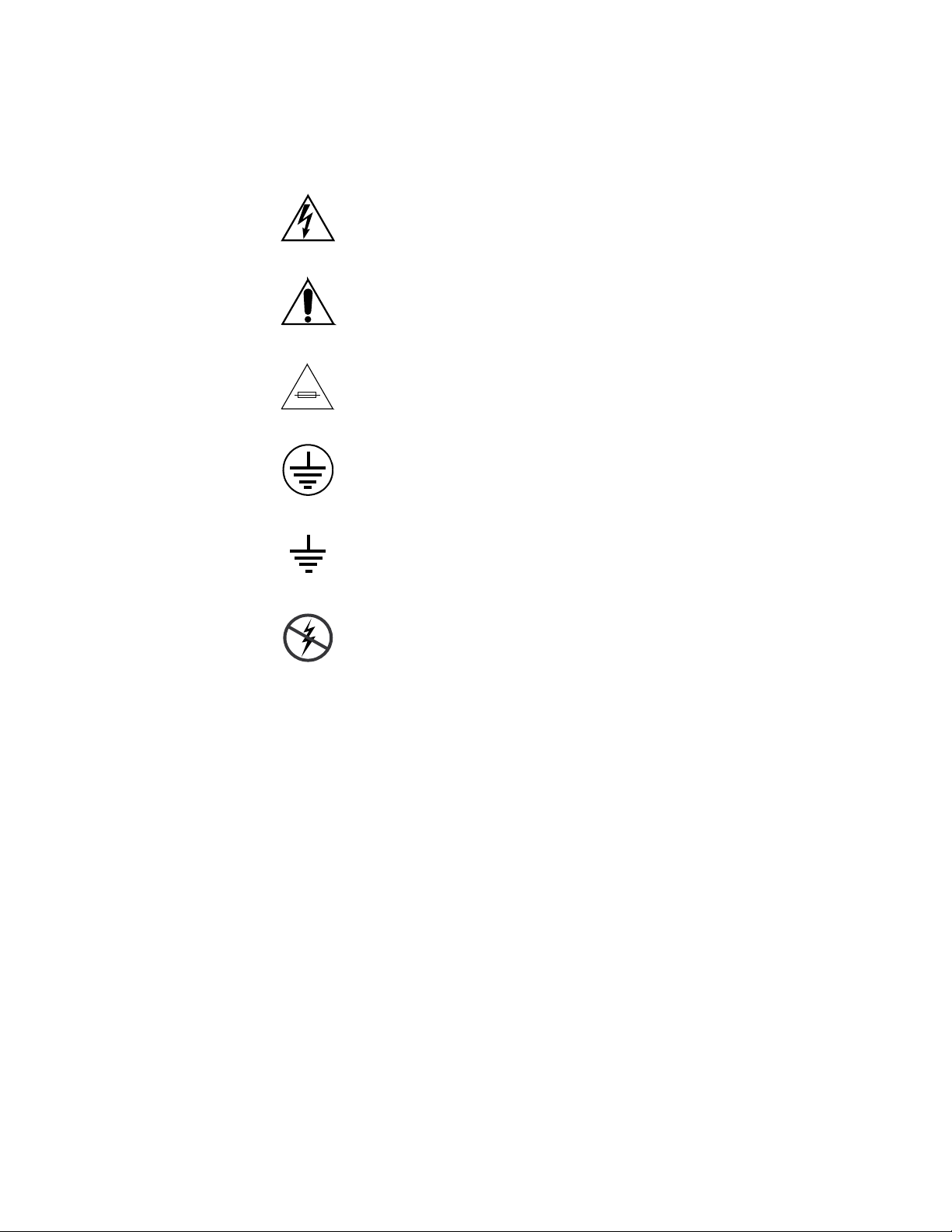
Symbols on the Product
The following symbols may appear on the product:
Indicates that dangerous high voltage is present within the
equipment enclosure that may be of sufficient magnitude to
constitute a risk of electric shock.
Indicates that user, operator or service technician should refer
to product manual(s) for important operating, maintenance,
or service instructions.
This is a prompt to note fuse rating when replacing fuse(s).
The fuse referenced in the text must be replaced with one
having the ratings indicated.
Identifies a protective grounding terminal which must be connected to earth ground prior to making any other equipment
connections.
Warnings
Identifies an external protective grounding terminal which
may be connected to earth ground as a supplement to an
internal grounding terminal.
Indicates that static sensitive components are present which
may be damaged by electrostatic discharge. Use anti-static
procedures, equipment and surfaces during servicing.
The following warning statements identify conditions or practices that can
result in personal injury or loss of life.
Dangerous voltage or current may be present — Disconnect power and remove
battery (if applicable) before removing protective panels, soldering, or
replacing components.
Do not service alone — Do not internally service this product unless another
person capable of rendering first aid and resuscitation is present.
Remove jewelry — Prior to servicing, remove jewelry such as rings, watches,
and other metallic objects.
Avoid exposed circuitry — Do not touch exposed connections, components or
circuitry when power is present.
10 7600 SD/HD/MHD-REF — Instruction Manual
Page 11

Safety Summary
Use proper power cord — Use only the power cord supplied or specified for
this product.
Ground product — Connect the grounding conductor of the power cord to
earth ground.
Operate only with covers and enclosure panels in place — Do not operate this
product when covers or enclosure panels are removed.
Use correct fuse — Use only the fuse type and rating specified for this
product.
Use only in dry environment — Do not operate in wet or damp conditions.
Use only in non-explosive environment — Do not operate this product in an
explosive atmosphere.
High leakage current may be present — Earth connection of product is essential
before connecting power.
Dual power supplies may be present — Be certain to plug each power supply
cord into a separate branch circuit employing a separate service ground.
Disconnect both power supply cords prior to servicing.
Cautions
Double pole neutral fusing — Disconnect mains power prior to servicing.
Use proper lift points — Do not use door latches to lift or move equipment.
Avoid mechanical hazards — Allow all rotating devices to come to a stop before
servicing.
The following caution statements identify conditions or practices that can
result in damage to equipment or other property
Use correct power source — Do not operate this product from a power source
that applies more than the voltage specified for the product.
Use correct voltage setting — If this product lacks auto-ranging power sup-
plies, before applying power ensure that the each power supply is set to
match the power source.
Provide proper ventilation — To prevent product overheating, provide equip-
ment ventilation in accordance with installation instructions.
Use anti-static procedures — Static sensitive components are present which
may be damaged by electrostatic discharge. Use anti-static procedures,
equipment and surfaces during servicing.
7600 SD/HD/MHD-REF — Instruction Manual 11
Page 12

Safety Summary
Do not operate with suspected equipment failure — If you suspect product damage
or equipment failure, have the equipment inspected by qualified service
personnel.
Ensure mains disconnect — If mains switch is not provided, the power cord(s)
of this equipment provide the means of disconnection. The socket outlet
must be installed near the equipment and must be easily accessible. Verify
that all mains power is disconnected before installing or removing power
supplies and/or options.
Route cable properly — Route power cords and other cables so that they ar not
likely to be damaged. Properly support heavy cable bundles to avoid connector damage.
Use correct power supply cords — Power cords for this equipment, if provided,
meet all North American electrical codes. Operation of this equipment at
voltages exceeding 130 VAC requires power supply cords which comply
with NEMA configurations. International power cords, if provided, have
the approval of the country of use.
Use correct replacement battery — This product may contain batteries. To
reduce the risk of explosion, check polarity and replace only with the same
or equivalent type recommended by manufacturer. Dispose of used batteries according to the manufacturer’s instructions.
Troubleshoot only to board level — Circuit boards in this product are densely
populated with surface mount technology (SMT) components and application specific integrated circuits (ASICS). As a result, circuit board repair at
the component level is very difficult in the field, if not impossible. For warranty compliance, do not troubleshoot systems beyond the board level.
12 7600 SD/HD/MHD-REF — Instruction Manual
Page 13

Regulatory Notices
Certifications and Compliances
FCC Emission Control
This equipment has been tested and found to comply with the limits for a
Class A digital device, pursuant to Part 15 of the FCC Rules. These limits
are designed to provide reasonable protection against harmful interference
when the equipment is operated in a commercial environment. This equip
ment generates, uses, and can radiate radio frequency energy and, if not
installed and used in accordance with the instruction manual, may cause
harmful interference to radio communications. Operation of this equip
ment in a residential area is likely to cause harmful interference in which
case the user will be required to correct the interference at his own expense.
Changes or modifications not expressly approved by Grass Valley Group
can affect emission compliance and could void the user’s authority to
operate this equipment.
-
-
Canadian EMC Notice of Compliance
This digital apparatus does not exceed the Class A limits for radio noise
emissions from digital apparatus set out in the Radio Interference Regula
tions of the Canadian Department of Communications.
Le présent appareil numérique n’emet pas de bruits radioélectriques
dépassant les limites applicables aux appareils numeriques de la classe. A
préscrites dans le Règlement sur le brouillage radioélectrique édicte par le
ministère des Communications du Canada.
EN55022 Class A Warning
In a domestic environment, products that comply with Class A may cause
radio interference in which case the user may be required to take adequate
measures.
-
7600 SD/HD/MHD-REF — Instruction Manual 13
Page 14

Regulatory Notices
Canadian Certified Power Cords
Canadian Certified AC Adapter
FCC Emission Limits
Canadian approval includes the products and power cords appropriate for
use in the North America power network. All other power cords supplied
are approved for the country of use.
Canadian approval includes the AC adapters appropriate for use in the
North America power network. All other AC adapters supplied are
approved for the country of use.
This device complies with Part 15 of the FCC rules.Operation is subject to
the following two conditions: (1) This device must cause not interference,
and (2) this device must accept any interference received, including inter
-
ference that may cause undesirable operation.
Certifications
Category Standard Designed/tested for compliance with:
Safety
Safety – This product has been evaluated and meets the following Safety
Certification Standards listed under the Safety category in the table below.
EMI – TThis product has been evaluated for Electromagnetic Compatibility
under the EN 55022 / EN 55024 standards for Emissions and Immunity and
meets the requirements listed under the EMI Category in the table below.
This product complies with Class A. In a domestic environment this
product may cause radio interference in which case the user may be
required to take adequate measures.
ANSI / UL60950 “Standard for Safety of Information Technology Equipment - Safety - Part 1: General
Requirements”, (ANSI/UL 60950-1, First Edition, Dated April 1, 2003, with revision
through and including November 26, 2003.)
IEC 60950 “Standard for Safety for Information Technology Equipment - Safety - Part 1: General
Requirements”, (IEC 60950-1, First Edition, 2001, Corrigendum 1:10-2002)
CAN/CSA C22.2, No. 60950 “Standard for Safety of Information Technology Equipment - Safety - Part 1: General
Requirements”, (CAN/CSA-C22.2 No. 60950-1-03. First Edition Dated April 1,
2003, with revisions through and including November 26, 2003)
EN60950 Safety of Information Technology Equipment, including Electrical Business Equip-
ment.
73/23/EEC Low Voltage Directive
14 7600 SD/HD/MHD-REF — Instruction Manual
Page 15

Category Standard Designed/tested for compliance with:
EMC Directive 89/336/EEC Information and Technology Equipment
EMI
EN 55022: 1998, Inc.
A1:2000 & A2:2003
Radio Disturbance Characteristics
EN 55024:1998, Inc.
A1:2000 & A2:2003
Immunity Characteristics
US FCC Class A
Canada FCC Industry Canada
Australia & New Zealand: AS/NZS 3548
Electromagnetic compatibility.
Product family standard for Information and Technology equipment for professional
use.
Emissions, Class A
EN 61000-3-2: Power Line Harmonic Emissions, Radiated Magnetic Field Emissions, Peak Inrush Current
EN61000-3-3: Mains voltage flicker and manual switching (Dmax = 4%)
Electromagnetic compatibility--Product family standard for Information and Technology equipment for professional use.
EN 61000-4-2:
Electrostatic Discharge “ESD” Immunity
EN 61000-4-3:
Radiated RF Electromagnetic Field Immunity
EN 61000-4-4:
Electrical Fast Transient/Burst “EFT” Immunity
EN 61000-4-5: Surge Immunity
EN 61000-4-6: Conducted RF Immunity
EN 61000-4-11: Voltage Dips, Short Interruptions and Voltage Variations
CISPR Pub. 22 (1997 Class A)
Regulatory Notices
7600 SD/HD/MHD-REF — Instruction Manual 15
Page 16

Regulatory Notices
16 7600 SD/HD/MHD-REF — Instruction Manual
Page 17

7600 SD-/HD-/MHD-REF Reference Generator
Product Overview
The 7600REF Synchronizing Pulse Generator is one of the most flexible SPG
units available on the market today. It is suitable for any digital or mixed
format environment where a high quality digital SPG is required. This
manual covers the installation and operation of the three available models
along with full technical specifications.
Refer to 7600REF Models on page 18 for specific functionality available for
each of the model types: 7600 SD-REF, 7600 HD-REF, and 7600 MHD-REF.
Each 7600REF model has the following basic functionality:
• Oven-controlled reference oscillator allowing the unit to be used either
as a master reference, or to follow another unit,
• Five analog outputs,
• Three SD SDI black outputs with four channels of embedded AES
silence and EDH,
• Two AES silence outputs,
• Each output selectable to either 525 or 625 operation,
• Each input individually timed,
• Dual power supplies that auto-sense line rates with separate mains
connections for power backup in the case of one power supply failure,
• Selectable clock output of 10 MHz/27 MHz/Word Clock,
• Looping Genlock input,
• 10 MHz Reference input
• ANALOG AUDIO/REMOTES connector that provides:
• A serial communication port,
• Analog audio output test tones,
• Power fail output status,
• Fan failure status, and GPI input output control connections.
7600 SD/HD/MHD-REF — Instruction Manual 17
Page 18

Product Overview
7600REF Models
7600 SD-REF Reference Signal Generator
7600 HD-REF Reference Signal Generator
Functionality specific to the three different 7600REF models is described
below.
This model features the following functionality:
• SD-SDI and analog video test signal patterns,
• Analog and AES audio test tones (including GLITS), and
• Full-field test patterns.
This model provides the same features as the SD version in addition to the
following:
• HD-SDI video test patterns, and
• A one slot HD Tri-level sync module provides 4 tri-level sync outputs,
each output individually configured from the front panel.
7600 MHD-REF Master HD Reference Signal Generator
This module expands the 7600 HD-REF model to include the following:
• A one slot GPS receiver module with a GPS antenna input and a
GPS 1 PPS output allows for locking to a high stability time and oscillator reference,
• Two LTC timecode outputs available on the LTC D-25 connector and
the addition of VITC timecode to the SDI signal, and
• Network Time Protocol (NTP) with both Client and Server modes. NTP
is intended for synchronizing function for changeover units (such as
the 7620PX) to keep them both in sync.
18 7600 SD/HD/MHD-REF — Instruction Manual
Page 19

Installation
Unpacking
Module/Software Installation
Installation
Follow the instructions below to unpack, install, and cable the 7600REF
frame.
Carefully unpack the unit from its packing box and check for signs of
damage. Check the contents of the box against the packing list and your
original order to ensure that you have received the correct parts.
In the event the unit has been damaged or does not match your order,
contact the Thomson Grass Valley Sales office listed on Contacting Grass
Valley on page 4.
All hardware modules are installed at the factory and shipped inside the
unit. Module functionality included in the model configuration depends
on the model type (see
ality included with the model is already installed and enabled.
7600REF Models on page 18). Any software function-
Rack Mounting
The 1 RU rack frame has integral rack mounting ears on the frame front
cover for direct mounting into a standard 19 inch rack. Carefully place the
unit in your rack and firmly attach it to the rack using four standard rack
screws (not provided).
CAUTION This unit has air intakes on one side of the unit and fan-assisted exhaust vents
on the other side of the unit. Ensure that these have an unobstructed air flow,
otherwise the unit will overheat. Pay particular attention to ensure that any
rack wiring or cable trays do not obstruct the vent. 60 mm (2.36 in.) of clear
space should be allowed between the vents and any potential obstruction.
7600 SD/HD/MHD-REF — Instruction Manual 19
Page 20
Installation
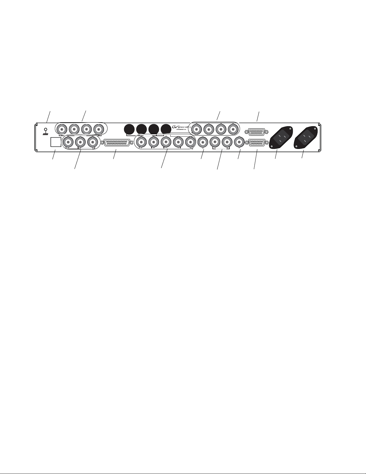
Rear Panel Connections
Grounding Lug Tri-level Sync Outputs
The rear connectors for the 7600REF frame are shown in Figure 1. Presence
of hardware and software functionality depends on the model you have
purchased (see
7600REF Models on page 18). Cabling instructions for each
of the connectors are explained in detail in this section.
Figure 1. 7600REF Rear Backplane
GPS Option/AES Unbalanced Audio
AES Audio Out (Balanced)
4321 432 1
TRI-
LEVEL SYNC
321
ETHERNET
Ethernet Port Analog Audio and Remote Control
SD/HD SDI Outputs
SD/HD SDI
ANALOG AUDIO/REMOTES
54321
Analog BB Reference/Test Outputs
Grounding Lug
The unit is provided with a single 4 mm (0.16 in.) ground lug on the far left
of the rear panel. Incoming mains ground from the IEC connector is inter
nally bonded to both the chassis and technical 0V to meet safety requirements and performance specifications. The stud allows the addition of an
ground strap, if required, for rack installations.
Ethernet Port
Each 7600REF model is equipped with a 10/100 base-T Ethernet port. This
port may be configured for either dynamic (DHCP) address mode or static
address mode. Configuration is done in the Setup menu (see
page 47). The 7600REF should be connected to the network in the same way
as other networked devices (such as a computer or printer) with a 1:1 CAT 5
RJ-45 cable.
TEST
SIGNALS
TEST
BB/ANALOG
AES 2GPS 1 PPS
AES 1
10/27/WC OUT
10/27/WC Out
Genlock Loop input
LOOP
GENLOCK
5/10 REF IN
5/10 Ref In
AES
LTC Out
47-63Hz
AC ONLY
AC/Mains InAC/Mains In
90-260V
2A-1A
47-63Hz
AC ONLY
90-260V
2A-1A
LTC
-
Setup Menu on
Tri-Level Sync Reference (7600 HD-REF and MHD-REF Models)
The TRI-LEVEL SYNC REFERENCE BNCs will output four independently
configured tri-level sync outputs. Setup is done in the Options menu (
HD
Tri-Level Sync (7600 HD-REF and 7600 MHD-REF Models) on page 69).
HD/SD SDI Test Outputs
The outputs from the SD/HD SDI TEST BNCs 1, 2, and 3, provide three
independently configured test signals. If the HD video capability is
present, further HD video formats are available. The three outputs are con
figured in the Digital Video menu (Digital Video Menu on page 33).
20 7600 SD/HD/MHD-REF — Instruction Manual
-
Page 21
These outputs also offer a combination of the following LTC (Longitudinal
Timecode) features with LTC capability (7600 MHD-REF model):
• Digital VITC (SMPTE S266) for standard definition signals only, and
• ATC (SMPTE RP188) for standard definition or high definition SD sig-
nals.
Analog Audio/Remotes
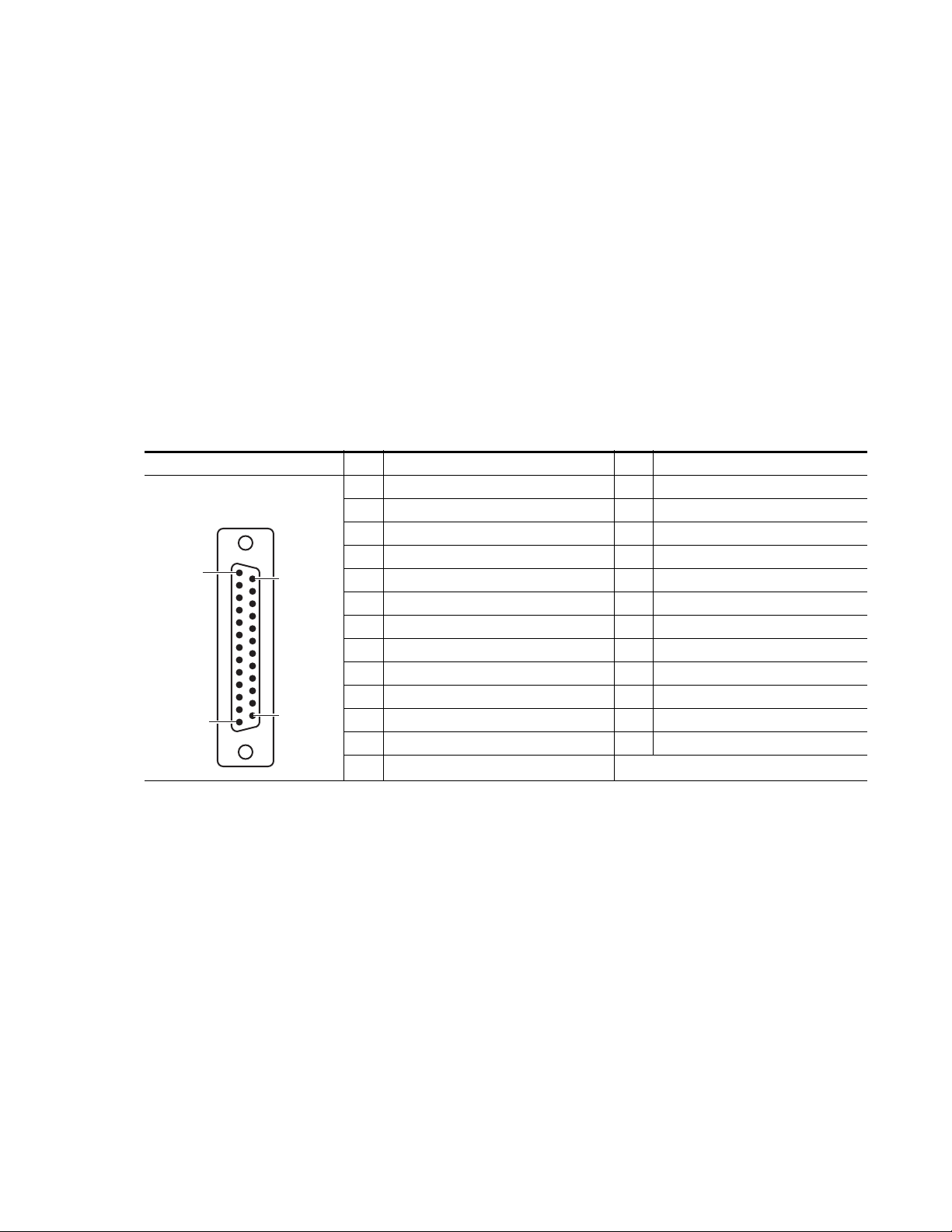
The 25 pin Sub-D connector labeled ANALOG AUDIO/REMOTES provides a serial communication port, the analog audio output tones, power
fail output status, fan failure status, and the GPI connections.
Pinouts for the ANALOG AUDIO/REMOTES connector are given in
Ta bl e 1. Each of the connector function is described in detail in this section.
Table 1. ANALOG AUDIO/REMOTES Connector Pinouts
ANALOG AUDIO/REMOTES Pin Function Pin Function
Power OK 1
Power OK 2
Fan OK - 2
GPIO - Input 2
GPIO - Input 1
RS422 CTS + (plus)
GPIO - Output 2
RS422 RTS + (plus)
Analog Audio Out 1 – (minus)
Analog Audio Out 2 – (minus)
Pin 1
Pin 13
D-25 Female
Pin 14
Pin 25
1 Fan OK -1 (Pair with pin 16. Closed if OK) 14
2 RS422 CTS – (minus) 15
3 RS422 RXD + (plus) 16
4 RS422 TSD + (plus) 17 GPIO - Output 1
5 RS422 RTS – (minus) 18
6 RS422 TXD – (minus) 19
7GND 20
8 RS422 RXD – (minus) 21
9GND 22
10 + 12V DC / 0.3A 23
11 Analog Audio Out 1 + (plus) 24
12 Analog audio Out 2 + (plus) 25 GND
13 GND
Installation
Fan Failure Output
This open collector output senses the current drawn by the cooling fans
fitted to the enclosure. The detector indicates a failure if a fan is stuck
and/or an open circuit is detected.
7600 SD/HD/MHD-REF — Instruction Manual 21
Page 22

Installation
GPI Inputs 1 and 2
The General Purpose Interface (GPI) inputs 1 and 2 are configured in software using the menus described in GPI Inputs 1 and 2 on page 22 to provide
any of the following functions:
•Force freerun mode
•Force Genlock mode
• Force external 10MHz lock mode
• Step through SDI output 1 test patterns
• Step through SDI output 2 test patterns
• Step through SDI output 3 test patterns
• Step through setup memories
The single-ended 7600 GPI inputs are activated when connected to a
ground connection on the 25 pin Sub-D connector as shown in
The two GPI inputs are pin 18 and pin 19 as listed in Tab le 1 on page 21. The
inputs can withstand +/- 20V and draw approximately 600uA when activated.
Figure 2.
Figure 2. Connection to GPI Inputs
7600Ref
GPI In
22 7600 SD/HD/MHD-REF — Instruction Manual
Page 23
Installation
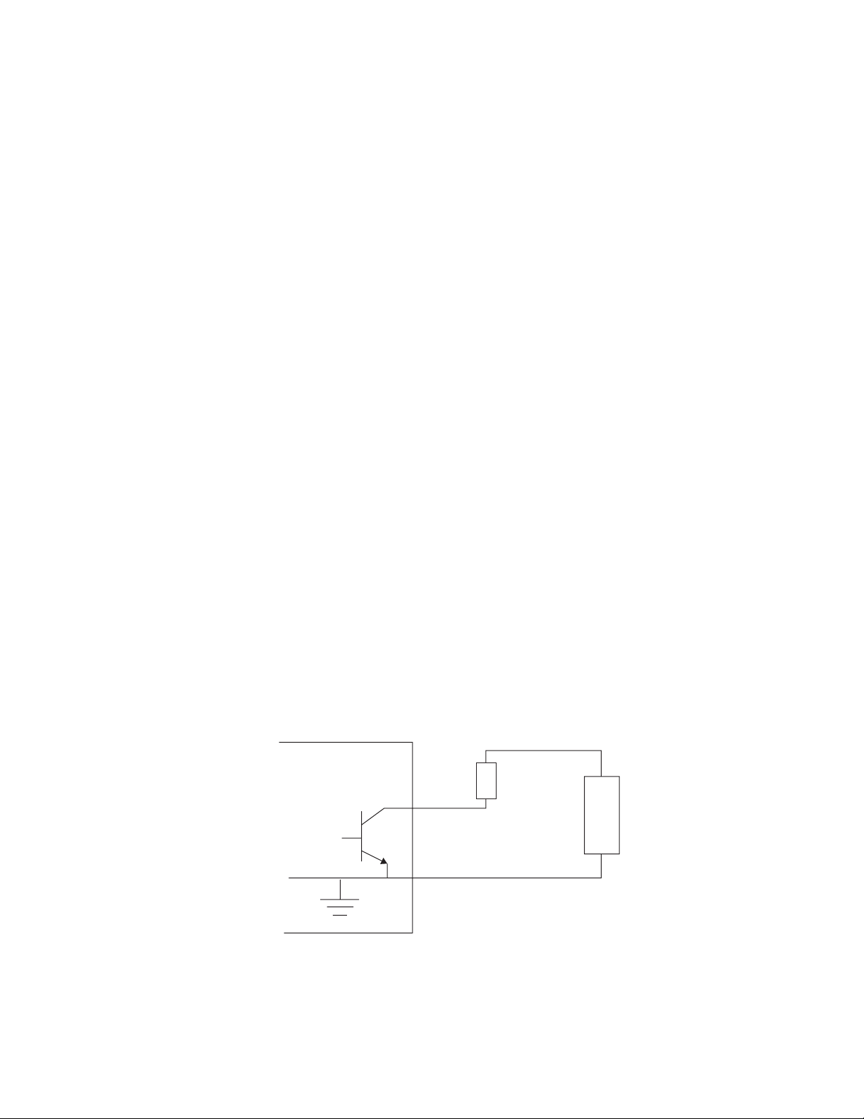
GPI Outputs 1 and 2
The General Purpose Interface (GPI) outputs 1 and 2 are configured in software using the menus described in GPI Outputs 1 and 2 on page 23 to
provide any of the following functions:
• Loss of genlock input
• Loss of external 10MHz reference
• Line lock error
• Field lock error
• Subcarrier lock error
• Illegal input ScH
• Diagnostic state alert
• Currently locked to external 10MHz
• Currently locked to external genlock
• Currently internal/freerun mode
The GPI outputs are single-ended open collector outputs with a
50V/200mA rating not to exceed 600 mW. The two GPI outputs are pin 17
and pin 21 as listed in
activated when one or more of the above conditions is true (for example,
loss of genlock input and/or line lock error).
To use an output, a load should be connected between the output and an
external power supply, with the negative end of the power supply connected back to the ground pin on the 25 pin Sub-D connector.
As an alternate to an external power supply, a +12V, 300mA feed is available on pin 10 of the Sub-D connector.
Figure 3. Connection to GPI Outputs
7600REF
GPO
Tab le 1 on page 21. It is intended that the GPO be
+
Load
Power Supply
_
7600 SD/HD/MHD-REF — Instruction Manual 23
Page 24
Installation
Analog BB Reference/Test
The five ANALOG BB REFERENCE/TEST BNCs provide independent
black burst reference signals and/or video test signal outputs as configured
in the Analog Video menus (see
10/27/WC Output
The 10/27/WC BNC provides either a 10MHz, 27MHz, or Word Clock
output. The output type is configured in the Setup/Clock Output menu
(
Setup Menu on page 47).
Genlock Loop Input
The GENLOCK LOOP BNCs provide an external genlock reference input
to the device. Genlock configuration is done in the Lock menu (
Menu on page 44).
5/10 Ref In
Analog Video Menu on page 36).
Lock Mode
The 5/10 REF IN BNC accepts either a 5MHz or 10MHz reference input.
AES 1/AES 2 and GPS BNCs (7600 MHD-REF Model)
The blanks for AES 1 and AES 2 unbalanced outputs and the GPS and 1PPS
BNCs shown in
Figure 8 on page 35 are present with the 7600 MHD-REF
model. Setup for AES outputs is described in Digital Video – AES on
page 35. GPS setup is described in GPS Setup (7600 MHD-REF) on page 52.
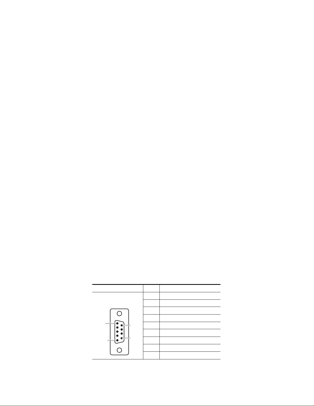
AES Outputs
The AES 9 pin Sub-D female connector provides balanced AES audio 1 and
2 outputs. The pinouts and their functions for this connector are
AES
shown in
described in Digital Video – AES on page 35.
Table 2. AES Pin Sub-D Pinout
Pin 1
Pin 5
Ta bl e 2. Setup of these outputs is done in the Audio/AES menu
AES Audio Out Pin Function
1 AES 1 + (plus)
D-9 Female
Pin 9
Pin6
2 AES 1 – (minus)
3Shield
4N/C
50V GND
6Shield
7 AES 2 + (plus)
8 AES 2 – (minus)
Shield
9
24 7600 SD/HD/MHD-REF — Instruction Manual
Page 25
AES audio may also be accessed through the unbalanced AES 1 and AES 2
BNCs when they are present. This requires the GPS function with the 7600
MHD-REF model. See GPS Setup (7600 MHD-REF) on page 52.
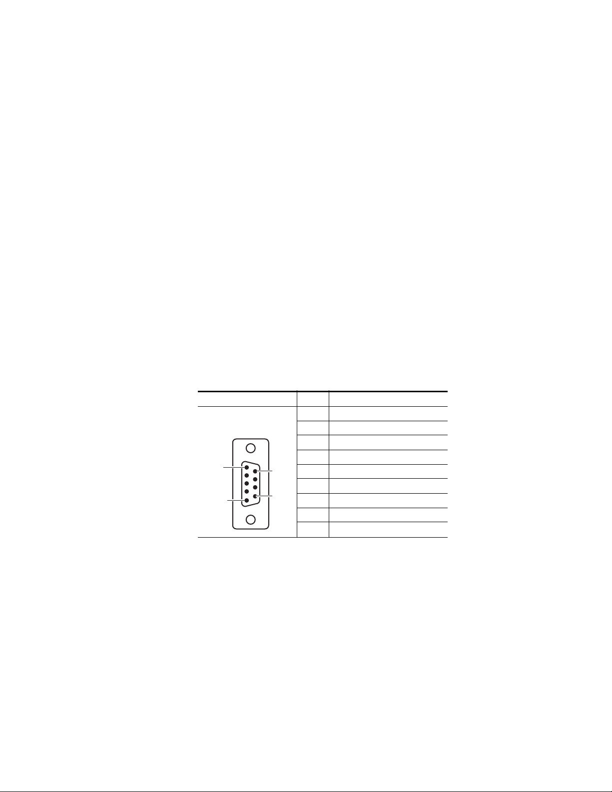
LTC Output (7600 MHD-REF Model)
The LTC (Longitudinal Timecode) 9 pin Sub-D female connector provides
LTC 1 and LTC 2 outputs with the 7600 MHD-REF model. The LTC function
provides the following:
• Two outputs of LTC
• Vertical Interval Timecode (VITC) superimposed on analog waveforms.
This is enabled or disabled in accordance with the current group
arrangement of the analog signal outputs.
• SDI outputs (see HD/SD SDI Test Outputs on page 20) will offer a com-
bination of Digital VITC (SMPTE S266) for standard definition signals
only and ATC (SMPTE RP188) for standard definition or high definition
SD signals.
The pinouts and their functions for this connector are shown in Table 3 .
Configuration is done from the Setup/LTC menu. Refer toTimecode Func-
tionality (7600 MHD-REF) on page 58.
Installation
Table 3. LTC Output Sub-D Pinout
LTC Out Pin Function
1 LTC 1 + (plus)
2 LTC 1 – (minus)
3Shield
4N/C
50V GND
6Shield
7 LTC 2 + (plus)
8 LTC 2 – (minus)
9
Pin 1
Pin 5
D-9 Female
Pin 9
Pin6
Shield
7600 SD/HD/MHD-REF — Instruction Manual 25
Page 26

Installation
AC Mains Connection and Fusing
CAUTION The power supply cord is used as the main power disconnection device.
Ensure that the socket outlet is located/installed near the equipment and is
easily accessible.
ATTENTION Le cordon d’alimentation est utilisé comme interrupteur général. La prise de
courant doit être située ou installée à proximité de l’équipement et être facile
d’accés.
Each 7600REF model is fitted with two independent AC mains power supplies. Each power supply has its own dedicated IEC mains plug on the rear
of the unit.
The correct power cords for the line standard of the region the product has
been shipped to are included in the shipping box. The power supplies used
in this the unit are a switch mode design and are auto-sensing to handle a
wide input voltage range. See Power (page 79) in the Specifications table
for the voltage and frequency ranges.
Power Supply Replacement
If one of the power supplies fails, a replacement unit can be acquired from
Customer Service and can be installed by the customer in the field.
To replace a 7600REF power supply:
CAUTION Make sure power to the unit is completely disconnected by removing both AC
cords from both power supply connections on the rear of the unit.
1. Remove the top cover of the frame by removing the 13 screws holding
the cover to the frame. Determine which power supply unit needs to be
replaced.
2. Tilt the frame up and on the bottom of the frame remove the two screws
holding the defective power supply unit to the frame chassis.
3. On the front of the power supply unit, remove the 2-pin connector
labeled J1 coming from the AC Main assembly. Note the orientation of
the connector when removing it.
4. On the rear of the power supply unit, remove the 4-pin rear connector
labeled J2 from the power supply attached to the cable coming from the
rear of the main circuit board. Note the orientation of the connector
when removing it.
5. Lift the defective power supply out of the chassis.
6. Install the new unit by reversing the steps above noting cable connector
orientation. These connectors are keyed so they cannot be installed
improperly.
26 7600 SD/HD/MHD-REF — Instruction Manual
Page 27

Operation
Front Panel Control Description
Operation
This section of the manual will cover using the front panel for configuration
and adjustments.
When the unit is powered up by connecting one or both of the AC Mains
connections, initialization messages will appear on the LCD display as the
unit configures the internal hardware.
Once initialization is complete, the following message indicating a normal
operational status will be displayed:
7600REF Main Menu
<Digital Video> Analogue Video Audio –>
The front panel is shown in Figure 4.
Figure 4. Front Panel Display
LCD Display
ADJUST knob
OK
Left Navigation Arrow Right Navigation Arrow
CANCEL
:Video buttons:
SDI and ANALOG
AUDIO
LOCK MODE
OPTIONS
STATUS
SETUP
The front panel has the following main functional areas (see Figure 4):
• A Liquid Crystal Display (LCD) used to show information to guide the
user through operating the various functions and to show status information.
• Front Panel Buttons
• Left and right arrow buttons for menu navigation
OK and CANCEL buttons to initiate or exit the currently selected func-
•
tion
ADJUST knob for parameter adjustment and/or left/right menu nav-
•
igation
•Video
SDI and ANALOG function buttons to access SDI or Analog
video menus
AUDIO function button to access menus for analog and AES audio
•
menus
7600 SD/HD/MHD-REF — Instruction Manual 27
Page 28

Operation
Basic Operation
• OPTIONS function button to access optional menus (options included
depend on model type, see 7600REF Models on page 18).
LOCK MODE function button to set up genlock modes
•
SETUP function button for miscellaneous configuration options
•
STATUS button for accessing diagnostic and status information
•
There are a number of basic concepts that once understood will simplify the
use of the unit as described below:
• Valid button pushes are indicated by a lamp lit inside a button. In most
cases, buttons without a lamp will not be prohibited, allowing rapid
changes between functions grouped on each button.
• Invalid button pushes will result in an informative message on the
LCD.
Selecting a Function
To change any parameter, the appropriate function button must first be
pushed. Once a function button is pushed, that button will remain illumi
nated and the others will turn off to provide a reminder of which function
is active.
Pushing a function button that has sub-functions under it will show the
name of the function and the first menu choice. For example, pushing the
SDI function button will bring you to the top of the SDI menu, SDI: Select
Channels
select the choices under this menu:
The selected choice will be surrounded by brackets < > indicating your
choice. Once you reach the desired choice, press the
menu. Depending on the sub-function chosen, either a further set of
sub-functions or the current value of the function is displayed. Where
appropriate, the currently selected option is indicated by asterisks, such as
* On * or * 1080p/23.98 * for example.
. Use either the ADJUST knob or the left or right arrow buttons to
-
SDI 1, SDI 2, or SDI 3.
OK button to enter that
28 7600 SD/HD/MHD-REF — Instruction Manual
Page 29

Changing Values
To change the value of a function, the ADJUST knob or the left or right arrow
buttons can be used.
In the case of numerical values, there are two functional modes:
Operation
• If the overall range of an adjustment is small the
alters the value by the smallest amount possible.
• If a wider range of adjustment is required, a Delta value system is used.
Use the right arrow button to select the Delta value in brackets and
adjust it to the desired resolution by turning the
press the left arrow button to select the value then adjust it with the
ADJUST knob.
An example of this would be setting the Line Offset for SDI 1. Scroll down
from Digital Video to SDI 1. Select Video Standard then Timing and scroll
to Line and press the OK button. The Line Offset menu will be present on
the LCD. Note the Delta value on the right of the LCD indicated by a triangle Delta symbol = 1. You may change the Delta resolution value to 10 or
100 with the knob.
Use the left arrow button to select the Pixel choice field and turn the knob
to change the values to 1, 10, or 100. Note that when the Delta value is 1, the
values change by steps of one pixel. With a Delta value of 10, the pixels
change by steps of 10, 20, 30 etc.). Selecting a Delta value of 100 allows you
to change the pixels by 100, 200, 300 etc. Change the Delta resolution if you
need a finer offset setting.
As the parameter is changed, the new value will be shown on the LCD. For
some functions, the unit responds by actually altering the value immediately. Otherwise the new value is applied when the
ADJUST knob always
ADJUST knob, then
OK button is pushed.
Leaving the Selected Function
Once the parameter has been set the unit can be returned to the normal
operating mode or another function chosen by one of the following
methods:
• Pressing the current (lit) function button will step up through the menu
structure until either the top (normal) level is reached or another menu
level of the same function is reached, at which point another menu can
be accessed by pressing the
•The
• At any time any other function key may be pressed causing the menu
7600 SD/HD/MHD-REF — Instruction Manual 29
OK button allow you to descend the menu structure and the current
function and the
structure to be traversed sideways. For example, having set an
CONTROL
back up through the menu first.
function, the SETUP key may be pushed without having to step
CANCEL key allows you to ascend the menu structure.
OK button.
OUTPUT
Page 30

Operation
Menu Timeout
In addition, there is a built-in timeout mechanism that will automatically
step back up through the menu structure until the top level is reached if a
key is not pressed within a preset time period. In any event, once the top
level is reached, the front porch will once again indicate valid functions by
lighting the relevant buttons.
The menu system may be set to auto-revert to the top level after a period of
inactivity. The option to enable/disable this feature is located in the
SETUP>>DISPLAY menu.
Front Panel Lock
Front panel controls may be locked to prevent inadvertent changing of settings. To lock or unlock the controls, press the Left and Right arrows simulaneously.
30 7600 SD/HD/MHD-REF — Instruction Manual
Page 31

Top Level Menu
The top level menu has the menu branches shown in Figure 5.
Figure 5. Top Level Menu
The content and features of each top level choice are summarized below. A
more detailed description of each top level choice is given later in this
manual. Note that the Options branch (on the right side of Figure 5) is only
displayed if specific options are included in the model. For functionality for
each model, refer to 7600REF Models on page 18.
Operation
Digital Video Menu
The Digital Video (SDI) menu provides full control of the configuration of
the three SDI outputs. The video standard, timing and appearance of each
output are controlled from this sequence of menus. In addition, the
embedded AES audio is enabled and configured for each output. If high
definition (HD) is present, additional choices will appear on the menu. See
Digital Video Menu on page 33.
Analog Video Menu
The Analog Video menu controls the format of the five analog video signals
provided on the Analog BB/Test BNCs on the rear of the frame. These are
arranged as a group of three plus a second group of two outputs. This
allows the group of three to be set as RGB or YUV in a single operation. See
Analog Video Menu on page 36.
Audio Menu
The Audio menu controls both the AES and analog audio outputs. For all
outputs, control of frequency and amplitude is available. In addition, for
the AES outputs, the sample rate and source ident may also be set. See
Audio Menu on page 41.
Lock Mode Menu
The Lock Mode genlock input menu sets the required format of the
incoming video signal and defines the behavior of the 7600REF when the
genlock signal is applied or removed. See
7600 SD/HD/MHD-REF — Instruction Manual 31
Lock Mode Menu on page 44.
Page 32

Operation
Setup Menu
The system Setup menu provides control of the basic configuration of the
7600REF and will be used primarily during the installation phase. Refer to
Setup Menu on page 47 for details.
System setup includes:
• Configuration of the LTC function (7600 MDH-REF model)
• Configuration of the Clock Output
• Comprehensive control of General Purpose Inputs and Outputs,
including:
• the input signal response mode
• the action resulting from a GPI trigger
• the event causing a GPO state change
• Check and control of the internal memory
• Setup of the real-time clock (RTC)
• Configuration of the Network Time Protocol (NTP) (7600 MHD-REF)
• Functions under the COMMS menu, including:
• Functions under the DISPLAY menu, including:
• Configure the 7600REF as Slave, allowing settings to be received from
Status Menu
The Status menu provides, for information only, the current version of the
software, hardware and firmware of the 7600REF. These three values will
be required when speaking to Technical Support.
In addition, a series of status error messages may be enabled for display on
the LCD screen. The final option on this menu displays a summary of the
current configuration status. See Status Menu on page 51 for details.
• configuration of the Ethernet port
• configuration of the Serial port
• enable and control timing of the menu timeout
• set the display contrast
a Master
Options Menu
The Options menu (page 32) lists the type of module fitted in each of the
three option slots. Options installed depend on the model type. If no option
module is installed, the text OPTION will be displayed. The text TLS refers
to the Tri-Level Sync option module.
32 7600 SD/HD/MHD-REF — Instruction Manual
Page 33

Digital Video Menu
The Digital Video menu provides control and configuration of the three SDI
video outputs. In models with HD capability, the menu is extended to
include further options.
From the top level, the menu branches to three identical sections. for clarity,
only SDI 1 is shown below in Figure 6. SDI 2 and SDI 3 are identical.
The SDI 1 menu then has five menu branches. If the LTC capability is
present (7600 MHD-REF), an extra VITC entry is also present. Refer to VITC
Within SDI on page 66.
Figure 6. Digital Video – SDI 1 Menu
Operation
Digital Video – Video Standard
The currently available digital video standards are listed in Ta bl e 4.
Table 4. Current Digital Video Standards
Description Lines/Frames Frame Rate (Hz) Scan
525
625
1080i / 59.94 1080 59.94 Interlaced
1080i / 60 1080 60 Interlaced
1080i / 50 1080 50 Interlaced
1080p / 30 1080 30 Progressive
1080p / 29.97 1080 29.97 Progressive
1080p / 25 1080 25 Progressive
1080p / 24 1080 24 Progressive
1080p / 23.98 1080 23.98 Progressive
720p / 60 720 60 Progressive
720p / 59.94 720 59.94 Progressive
720p / 50 720 50 Progressive
720p / 30 720 30 Progressive
720p / 29.97 720 29.97 Progressive
720p / 25 720 25 Progressive
720p / 24 720 24 Progressive
720p / 23.98 720 23.98 Progressive
7600 SD/HD/MHD-REF — Instruction Manual 33
Page 34

Operation
Digital Video – Test Patterns
Select the SDI 1 test pattern parameters from the Test Pattern menu shown
Figure 7.
in
Figure 7. Digital Video – Test Patterns Menu
34 7600 SD/HD/MHD-REF — Instruction Manual
Page 35

Digital Video – Timing
Adjust the SDI 1 timing with the Timing menu shown in Figure 8.
Figure 8. Digital Video – Timing Menu
Digital Video – AES
Configure the AES audio outputs with the AES menu shown in Figure 9.
Operation
Figure 9. Digital Video – AES Menu
7600 SD/HD/MHD-REF — Instruction Manual 35
Page 36

Operation
Analog Video Menu
Digital Video – EDH
Enable (On) or disable (Off) EDH with the EDH menu shown in Figure 10.
Note This menu is only visible if the video output standard is set to a Standard Def-
inition signal.
Figure 10. Digital Video – EDH Menu
The top level menu is shown in Figure 11 on page 37. The five available
analog output connectors are arranged as follows:
• A group of three, configured as:
• All Black Burst (BB) (see Analog Video – All Black and Burst on
page 38)
• YUV test pattern (see Analog Video – YUV on page 39)
• A single composite video signal, plus two BB outputs (see Analog
Video – Composite/BB/BE on page 40)
• RGB test pattern (Analog Video – RGB on page 40)
• A YC test pattern plus a single BB output (see Analog Video – YC/BB
on page 40)
• A group of two, configured as:
• Both Black and Burst
• A single composite video signal, plus one BB Output
36 7600 SD/HD/MHD-REF — Instruction Manual
Page 37

Operation
The menus follow two common themes, either for the test pattern signals
or for Black Burst configuration as shown in
Figure 11. Analog Video – Top Level Menu
Figure 11.
7600 SD/HD/MHD-REF — Instruction Manual 37
Page 38

Operation
Analog Video – All Black and Burst
For configuring the analog outputs for all black burst refer to the menu
shown in
Figure 12. Analog Video – All Black Burst Menu
Figure 12.
38 7600 SD/HD/MHD-REF — Instruction Manual
Page 39

Analog Video – YUV
For configuring the analog outputs for YUV refer to the menu shown in
Figure 13.
Figure 13. Analog Video – Analog Outputs YUV
Operation
7600 SD/HD/MHD-REF — Instruction Manual 39
Page 40

Operation
Analog Video – Composite/BB/BE
For configuring the analog outputs for 1 composite output, and 2 Black
Burst outputs refer to the menu shown in
Figure 14. Analog Video – Composite and Black and Burst
Analog Video – RGB
For configuring the analog outputs for RGB, the menu is the same as Analog
Video – YUV on page 39.
Figure 14.
Analog Video – YC/BB
For configuring the analog output 1 and 2 for YC and 3 for Black Burst use
the menu shown in
Figure 15. Analog Video – Composite and Black and Burst
Figure 15.
40 7600 SD/HD/MHD-REF — Instruction Manual
Page 41

Audio Menu
Operation
The top level audio menu has two branches (Figure 16):
•AES
•Analog
Figure 16. Audio Top Level Menu
7600 SD/HD/MHD-REF — Instruction Manual 41
Page 42

Operation
Audio – AES 1 and AES 2
Use the menu shown in Figure 17 to set up the AES 1 audio outputs. The
menu for AES 2 is identical.
Figure 17. AES 1 Menu
42 7600 SD/HD/MHD-REF — Instruction Manual
Page 43

Audio – Analog
Use the menu shown in Figure 18 to set up the Analog audio outputs. The
menu for AES 2 is identical.
Figure 18. Analog Audio Menu
Operation
7600 SD/HD/MHD-REF — Instruction Manual 43
Page 44

Operation
Lock Mode Menu
The Lock Mode top level menu is shown in Figure 19.
Figure 19. Genlock Top Level Menu
The Lock Mode settings of the unit (for example, the current genlock mode
and timing offsets) may be changed by entering the Lock Mode top level
menu and setting the following:
Mode – changes the basic genlock mode from the mode selections (Gen-
•
lock – Mode on page 45).
Genlock Loss – sets the behavior of the unit following loss of the genlock
•
signal (Genlock Loss on page 45).
Field Lock – alters the field lock action – instantaneous or slow lock (Gen-
•
lock – Field Lock on page 46).
Input Standard – refer to Genlock – Input Standard on page 46.
•
To enter a sub-menu, scroll to the function and select the
OK button.
44 7600 SD/HD/MHD-REF — Instruction Manual
Page 45

Genlock – Mode
Select the Genlock mode required by using the Adjust knob or the Left and
Right arrow buttons. All available modes are discussed below.
Note Please be aware that the mode will change immediately when an option is
• Internal Free Run – sets the unit to be free running, relying on the internal
oven oscillator for stability. The ScH of the unit will be set to zero.
External 10MHz – sets the unit to genlock to the 10MHz input. There will
•
be no fixed phase relationship with any other units lock to this signal.
The ScH of the unit will be set to zero.
Manual SC Phasing – sets the unit to genlock to the video input. The sub-
•
carrier phase offset may be adjusted as required.
Force Strict ScH – sets the unit to genlock to the video input. The ScH of
•
the outputs of the unit is forced to zero regardless of the genlock input
ScH. This is achieved by moving the line timing with respect to the
genlock input until the correct ScH phase results.
Operation
selected.
•
•
Genlock Loss
Select the operational mode of the unit following loss of the genlock signal
from the following choices:
• Revert to Internal – if the external reference signal is removed, the unit will
•
•
Note Note that if the unit is powered up in this mode with no genlock input applied,
Follow External SC Phase – sets the unit to genlock to the video input. The
subcarrier output phase is set to be the same as the input genlock video.
Sync Lock Only – sets the unit to genlock to the video input. The system is
genlocked using only the sync information of the genlock video input.
the ScH phase of the output is forced to zero (correct).
use the internal oven maintained oscillator as its master oscillator.
External 10 MHz – if the genlock video input is removed, the unit will use
the 10MHz input as its master oscillator. if the 10Mhz input is not
present when the video input fails, the unit will use the internal oven
maintained oscillator as its master oscillator.
Flywheel – if the genlock video input is removed, the unit will continue
to operate - flywheel - at the same frequency as the genlock input just
removed.
the 7600REF outputs may not be within specification.
7600 SD/HD/MHD-REF — Instruction Manual 45
Page 46

Operation
Genlock – Field Lock
Select the mode required from the following choices:
• Crash – sets the unit to lock near instantaneously to the field information
of an applied genlock input. This is the normal state of operation.
Line Drop – sets the unit to lock to the field information of an applied
•
genlock video input by moving the outputs one line nearer the genlock
video input every 5 fields unit the unit is locked. This mode is useful if
the instant locking of the Crash mode is found to upset any downstream equipment.
Genlock – Input Standard
Select the video line standard of the input signal.
• 525
• 625
• Auto detect
46 7600 SD/HD/MHD-REF — Instruction Manual
Page 47

Setup Menu
Operation
The Setup top level menu is shown in Figure 20.
Figure 20. Setup Top Level Menu
The Setup menu has the following menu branches:
• Configuration of the Clock Output
• Comprehensive control of General Purpose Inputs and Outputs,
including:
• the input response mode
• the action resulting from a GPI trigger
• the event causing a GPO state change
The GPIO sub-menu for setting up GPI control is explained and shown in
Setup – GPI Control on page 48.
7600 SD/HD/MHD-REF — Instruction Manual 47
Page 48

Operation
Setup – GPI Control
The menu shown in Figure 21 shows the following:
• Configure GPI – the actions which the 7600REF will carry out when a
control signal is applied to GP Input 1 or 2.
• Configure GPO – the signal which will appear on the 7600REF output
when a defined condition occurs. As can be seen, this is normally an
error or alarm condition.
GPI wiring is described in GPI Inputs 1 and 2 on page 22 and GPI Outputs 1
and 2 on page 23.
Figure 21. GPIO Menu
48 7600 SD/HD/MHD-REF — Instruction Manual
Page 49

Setup – More
The Setup More menu is shown in Figure 22 and includes options to:
• Manage internal memory banks 1-4. A complete operational setup may
• Setup the real-time clock (RTC).
• Configure the Network Time (NTP) capability (7600 MHD-REF).
• Configure communication with the 7600REF by:
• Adjust the LCD display by:
• Configure the 7600REF as Client (Slave), allowing settings to be
Operation
be stored or retrieved at any time.
• Ethernet port
• Serial port (RS232 or RS422)
• Setting the display contrast
• Controlling the menu time-out
retrieved from a Server (Master). This is useful when configuring a pair
of units in fail-safe mode. Only the Master need be configured; the
Slave can request settings from a Master.
• Upgrade the 7600REF, including:
•Firmware updates
Figure 22. Setup More Menu
7600 SD/HD/MHD-REF — Instruction Manual 49
Page 50

Operation
Setup – Comms
The Comms menu (Figure 23) provides network and serial port setup.
The Ethernet Port is used to connect the 7600REF to a LAN, or to a laptop
PC when performing upgrades. The settings required are primarily governed by the network arrangements at the site and are explained in Local
Area Networks on page 70. A network connection will also be required if the
NTP function in the 7600 MHD-REF model is used.
The serial port is used primarily during the manufacturing process but in
RS422 mode if offers a range of functions. Contact Technical Support for
more information.
Figure 23. Comms Menu
50 7600 SD/HD/MHD-REF — Instruction Manual
Page 51

Status Menu
Operation
A dedicated STATUS button provides diagnostic and status information
(
Figure 24) in read-only format. Should an error condition such as loss of
genlock occur, the lamp in the STATUS button will flash to draw the attention
of the operator. The display text, which can be displayed by pressing the
STATUS button, will change to indicate that an error message is available.
Pressing the STATUS button at any time will display the unit’s current status.
Figure 24. Status Menu
7600 SD/HD/MHD-REF — Instruction Manual 51
Page 52

Operation
Option Menus
Available options on the different model types are enabled at the factory.
An option will appear in the menu trees if it is included in the model. Refer
to
7600REF Models on page 18 for the list of options included in each model.
GPS Setup (7600 MHD-REF)
The GPS module comes with the 7600-MHD-REF model and is installed in
Slot 1. The Global Positioning System (GPS) is currently the only fully-func
tional Global Navigation Satellite System. More than two dozen GPS satellites are in medium Earth orbit, transmitting signals allowing GPS receivers
to determine the receiver’s location, speed, and direction.
GPS also provides a precise time reference used in many applications
including synchronization of telecommunications networks.
The GPS BNCs (and the AES unbalanced outputs) active on the 7600
MHD-REF model are shown in Figure 25.
-
Figure 25. GPS BNCs
AES 1 and 2 Unbalanced
Audio Outputs
1
AES 1
10/27/WC OUT 5/10 REF IN
• The 1PPS (1 Pulse Per Second) output is a precise TTL level pulse which
may be terminated into 75 ohm when connected into external equipment.
• The GPS antenna input should be connected to a high quality 50R GPS
antenna.
• The AES 1 and 2 outputs provide an unbalanced duplicate of the
signals on the AES 9 pin Sub-D connector (Tab le 2 on p age 24). These
are not related GPS operation and are provided for convenience from
this module.
AES 2GPS 1 PPS
GPS Receiver
Antenna Input
LOOP
GENLOCK
GPS Receiver
1PPS Output
52 7600 SD/HD/MHD-REF — Instruction Manual
Page 53

Operation
GPS Antenna Requirements
The GPS module requires an external antenna with the following characteristics:
• Active single antenna is power from the 7600REF antenna connector
• 3V DC antenna is required
• Reception frequency optimized for 1575.42 MHz
• 10 dB to 50 dB gain as measured at receiver input (Antenna perfor-
mance dictated by antenna manufacturer)
• Connection by coaxial cable terminated in 50 ohm BNC male connector
• Maximum cable length controlled by signal strength and location.
Trimble cable is 25m/75ft (N.B. standard cable length is 5m or less on
some antennas.) Each extra interconnect will attenuate the signal and
could increase acquisition/response time.
• Mounting – ideally clear 360 degrees view of sky. Weatherproof mate-
rial for fixed installation.
Magnetic patch antennas suitable for vehicle mounting will also be satisfactory; the signal may be improved by mounting on minimum 3 inch/75mm
square steel plate.
Recommended antenna types See Disclaimer below):
• Trimble Bullet 3 with 75 ft cable. N or F to BNC adapter required. 3V or
as required.
TM
•Oncore
•Oncore
• Super Electronics Co.
• Gilsson
2000 (Matching connectors and cable will also be required)
TM
Hawk with BNC
TM
GA001D105001S (fit own male BNC)
TM
External GPD Antenna (specify male BNC and cable length)
Disclaimer
Thomson Grass Valley Inc. is not connected in any way with any of the
above companies. The information above is given in good faith from infor
mation in the public domain at the time of this manual release. Many
similar antennae are available and specifications change over time. Some
degree of experimentation may be required if the location is shrouded by
adjacent structures, buildings, etc. Excessive cable length will adversely
affect performance.
-
Thomson Grass Valley, Inc. has no control over the local conditions in
which the equipment is installed and the customer is expected to have
carried out a site survey to ensure that sufficient signal can be provided for
the equipment to work in a satisfactory manner. Thomson Grass Valley, Inc.
will not be held responsible for failures caused by poor installation, main-
7600 SD/HD/MHD-REF — Instruction Manual 53
Page 54

Operation
tenance, or changes in local conditions in which the required signals have
been degraded such that time synchronization is lost.
Acquisition Process
With satisfactory reception, the acquisition process commences automatically and takes around 15 minutes. An enhanced mode (Site Survey) is suitable for static installation and may be initiated from the Site Survey
selection on the GPS menu. A complete Site Survey can take around 2
hours. Once completed, it provides more accurate timing signals.
A 1 Pulse Per Second (1PPS) signal waveform is illustrated in
Figure 26. 1PPS Signal Waveform
The leading edge of the 6 ms wide, positive going pulse provides the timing
reference plane for locking external equipment.
Internally, this signal locks the 27MHz PLL Oscillator such that PAL output
signals are both frequency locked and phase locked. Any NTSC output
signals are frequency locked but cannot be phase locked.
54 7600 SD/HD/MHD-REF — Instruction Manual
Page 55

Operation
GPS Menu Structure
With the 7600 MHD-REF model, the GPS function will appear on the top
level menu. This opens the menu branch shown in
This menu is detailed below.
Status – see Status Menu on page 51.
•
PPS Lock – it the PPS Lock mode is set to On, it only affects the Internal
•
Free Run mode of genlock. The internal oscillator is then locked to the
GPS reference.
Crash Lock – if the Crash Lock mode is set to On, the output signal is
•
subject to a single large disturbance followed by a period of approximately 10 minutes for settling. If the Crash Lock is Off, convergence
may take many hours.
ATR Lock – ATR (Absolute Time Reference) is covered by SMPTE Pro-
•
posal 404 and is also known as SMPTE epoch. It defines a starting point
of midnight on January 1st, 1958, at which time all generating equipment is deemed to be phase locked By accurate determination of
current GPS time, any ATR equipment may be locked together again.
ATER also provides a time (and date) source for timecode generated by
the 7600 unit.
Figure 27 on page 56.
If ATR Lock mode is On, the unit will also perform a Crash Lock, independently of the Crash Lock mode described above.
• Site Survey – a site survey can take up to 2 hours to complete. It may be
initiated at any time, but would normally only be carried out when the
unit is in a fixed installation location with a high quality antenna. Status
of the Site Survey is shown in the Status sub-menu shown in Figure 28
on page 57.
Cable Length – provided compensation for the propagational delay of the
•
antenna cable.
7600 SD/HD/MHD-REF — Instruction Manual 55
Page 56

Operation
Figure 27. GPS Control.Menu
56 7600 SD/HD/MHD-REF — Instruction Manual
Page 57

GPS Status
The GPS Status menu shown in Figure 28 is a read-only menu.
Some information about this menu is listed below.
Satellites – the time taken to acquire satellites can be 10 or 15 minutes,
•
since the almanac data is broadcast fairly infrequently.
Current Mode – will be displayed as:
•
3D Fix Mode – when a standard lock has been achieved.
•
Position Hold – following a successful Site Survey
•
Site Survey – status is displayed as:
•
• In Progress
•Not In Progress
Figure 28. GPS Status Menu
Operation
7600 SD/HD/MHD-REF — Instruction Manual 57
Page 58

Operation
Timecode Functionality (7600 MHD-REF)
Timecode is available with the 7600 MHD-REF model and provides the following:
• 2 outputs of Longitudinal Timecode (LTC) on the LTC 9 pin Sub-D connector (refer to LTC Output (7600 MHD-REF Model) on page 25 for con-
nector pinout information).
• Vertical Interval Timecode (VITC) superimposed on analog video
waveforms. This is enabled or disabled in accordance with the current
group arrangement of the analog signal outputs.
• Each SDI output offers a combination of:
• Digital VITC (SMPTE S266) for standard definition signals only.
• ATC (SMPTE PRP188) for standard definition or high definition SD
signals.
On the 7600 MHD-REF model, the LTC functions, Timecode JAM and LTC
menu branches are accessed from the Setup menu explained below and
shown in Figure 29 on page 60.
Timecode Jam
This is the process of setting the time carried on the timecode stream. To
avoid discontinuity, it is important to carry this out carefully. The first
branch of this submenu list base oscillator frequencies (23.98Hz etc.) used
to drive the range of output signals. for example, to Jam the timecode for a
625 signal, select the 25 Hz option.
This submenu has the following modes:
Jam Source
•
• Manual: enter values manually
• RTC: uses the Real Time Clock, with the option to apply a manual
offset.
•JAM Mode
• Auto: sets a scheduled time
• Manual: on command
• JAM!: initiates the JAM procedure.
• Show Clock: shows the time currently carried on the LTC stream.
58 7600 SD/HD/MHD-REF — Instruction Manual
Page 59

Operation
LTC
This submenu has the following modes:
• Mode – turns the timecode On or Off.
Frame Rate – since LTC is not encoded within a video signal, the frame
•
rate must be set either explicitly or by linked association with another
system output. Refer to LTC – Frame Rate Sub Menu on page 61.
Drop/Non-Drop – relates to 525/NTSC line timecode and determines
•
whether frames are dropped to compensate for the non-integer number
of NTSC frames per second.
Color Frame Flag – this is a single bit within the data stream which indi-
•
cates whether timecode is related to the video signal. This menu option
allows the operator to turn this bit On or Off.
Timecode Offset – an additional offset may be applied to any timecode
•
output with a value between -23h: 59m: 59s and +23h: 59m: 59s. The
default is 0h: 0m: 0s. This offset is applied immediately. Timecode
outputs using the same oscillator frequency will remain “in-step” using
the Timecode JAM settings applied in the Timecode JAM menu.
Binary Group Bits – the primary function of the Flag Bits is to allow the
•
operator to embed a date code within the data stream since timecode
represents only embedded time. This conforms to SMPTE S309. Refer
to LTC – Binary Group Sub Menu on page 62.
7600 SD/HD/MHD-REF — Instruction Manual 59
Page 60

Operation
Figure 29. Setup –LTC Menu
60 7600 SD/HD/MHD-REF — Instruction Manual
Page 61

Operation
LTC – Frame Rate Sub Menu
The Frame Rate sub menu is shown in Figure 30. Since LTC is not contained
within a video waveform, the timing must either be set explicitly or allied
to one of the signal outputs.
Figure 30. LTC Frame Rate Sub Menu
7600 SD/HD/MHD-REF — Instruction Manual 61
Page 62

Operation
LTC – Binary Group Sub Menu
The LTC Binary Group sub menu is shown in Figure 31.
Figure 31. LTC Frame Rate Sub Menu
62 7600 SD/HD/MHD-REF — Instruction Manual
Page 63

Operation
VITC Within Analog Waveform
With timecode functionality, an extra menu item will appear as appropriate. The example below in Figure 32 shows the VITC item added to the
BB1 (Black and Burst Option 1) menu tree.
Figure 32. VITC Added to Analog Waveform
7600 SD/HD/MHD-REF — Instruction Manual 63
Page 64

Operation
The menu shown in Figure 32 on page 63 is essentially identical to the
menu shown in Analog Video – All Black and Burst on page 38.
The additional branch for VITC is shown below in Figure 33. The other
items in this menu are explained previously in the Timecode Functionality
(7600 MHD-REF) on page 58.
Figure 33. VITC Menu
64 7600 SD/HD/MHD-REF — Instruction Manual
Page 65

Operation
The additional branch for VITC is shown below in Figure 33. The other
items in this menu are explained previously in the Timecode Functionality
(7600 MHD-REF) on page 58.
Figure 34. VITC Menu
7600 SD/HD/MHD-REF — Instruction Manual 65
Page 66

Operation
VITC – Lines Menu
There is no Drop entry on the VITC menu when the output in question is
set to PAL mode. However, there is an extra Lines menu option on the VITC
menu to allow control over which line the VITC signal is inserted into as
shown in
lines in each field which have VITC inserted.
Figure 35. VITC – Line Menu
Figure 35. Here Line 1 and Line 2 indicates the first and second
VITC Within SDI
On the 7600 MHD-REF model with Timecode, an extra menu will appear
in the tree for SDI 1 and SDI 2. The menu in
as the one for SDI 1 shown in Figure 6 on page 33.
Figure 36. VITC within SDI Menu
Figure 36 is essentially the same
66 7600 SD/HD/MHD-REF — Instruction Manual
Page 67

Operation
Many of the menus are the same as those in the previous LTC section. The
additional ATC menu is shown in
This menu allows selection of the following:
ATC Duplicate – this flag indicates where the ATC data to be re-encoded
•
as a VITC signal appears on 1 or 2 lines in each field.
ATC Line – sets the line number where the ATC data to be re-encoded as
•
a VITC signal will appear.
Figure 37. SDI ATC Menu
Figure 37.
7600 SD/HD/MHD-REF — Instruction Manual 67
Page 68

Operation
Network Time Protocol (NTP) (7600 MHD-REF Model)
This function included with the 7600 MHD-REF model offers the following
for Master/Slave operation:
• Both Client and Server modes are available
• If installed, the menu will off Server, Client, and Disabled. Client and
Server are mutually exclusive. NTP is intended for change-over units to
keep them both in sync.
• The Client can sync to any Internet NTP server.
• When acting as a server the 7600REF should, ideally, have a GPS
module installed (included with the 7600 MHD-REF model) but this is
not a requirement. Even if the server is free running, a slaved unit can
still sync to it.
68 7600 SD/HD/MHD-REF — Instruction Manual
Page 69

HD Tri-Level Sync (7600 HD-REF and 7600 MHD-REF Models)
The four available Tri-level BNCs can be individually configured from the
menu according to
selected from the 7600REF menu. The scan format is indicated by P (Progressive) or I (Interlaced).
Table 5. Tri-Level Sync Configuration
Number Description Lines/Frame Frame Rate Scan
1 1920x1080/60/1:1 1125 60 P
2 1920x1080/59.94/1:1 1125 60 P
3 1920x1080/50/1:1 1125 50 P
4 1920x1080/60/2:1 1125 60 I
5 1920x1080/59.94/2:1 1125 60 I
6 1920x1080/50/2:1 1125 50 I
7 1920x1080/30/1:1 1125 30 P
8 1920x1080/29.97/1:1 1125 30 P
9 1920x1080/25/1;1 1125 25 P
10 1920x1080/24/1:1 1125 24 P
11 1920x1080/23.98/1:1 1125 24 P
12 1920x1080/30/sF 1125 30 I
13 1920x1080/29.97/sF 1125 30 I
14 1920x1080/25/sF 1125 25 I
15 1920x1080/24/sF 1125 24 I
16 1920x1080/23.98/sF 1125 24 I
17 1280x720/60/1:1 750 60 P
18 1280x720/59.94/1:1 750 60 P
19 1280x720/50/1:1 750 50 P
20 1280x720/30/1:1 750 30 P
21 1280x720/29.97/1:1 750 30 P
22 1280x720/25/1:1 750 25 P
23 1280x720/24/1:1 750 24 P
24 1280x720/23.98/1:1 750 24 P
25 720x483/59.94/1:1 525 60 P
26 6 Hz (30/24) 6HZ - -
27 6 Hz (29.97/23.98) 6Hz - -
28 625/50 625 50 I
29 525/59.94 525 60 I
Ta bl e 5 below. The first column indicates the number
Operation
7600 SD/HD/MHD-REF — Instruction Manual 69
Page 70

Using a TFTP Server
Using a TFTP Server
The use of an TFTP server with the 7600REF models allows the customer to
upgrade software in the field, and, if necessary, generate a copy of the 7600
log file to send to Technical Support for troubleshooting purposes or option
enabling.
The 7600 log is a unique digital signature for each 7600 frame and describes
the options that have been enabled. As mentioned earlier, options come
already enabled from the factory so using this function to create a log file
for enabling options should not be required unless requested by Customer
Service.
However, software upgrades may be preformed in the field using the TFTP
server. See Updating 7600 Software on page 73.
To prepare a TFTP Server refer to Preparing a TFTP Server on page 71. The
suggested shareware application is called Solarwinds and can be downloaded from http://solarwinds.net/downloads if required.
Run the installing program, accepting all default options. Note that you
may require Administrative rights under Windows to install new applications.
Local Area Networks
In order to communicate with the TFTP server, the 7600REF must have a
valid IP Address in the same subnet (range) as the server.
• If communication is via a company network, then IP addresses may be
automatically allocated using DHCP.
• If the 7600REF is connected to a small network specifically established
for technical equipment, then static IP addresses may be in use and the
7600 should be configured accordingly.
• If the 7600REF is not currently connected to a LAN, Solarwinds may be
installed on a laptop which is then connected to the 7600REF with a
crossover cable.
The 7600REF Ethernet port is configured using the Setup menu, then navigating to the Comms menu. Refer to Setup – Comms on page 50.
70 7600 SD/HD/MHD-REF — Instruction Manual
Page 71

Preparing a TFTP Server
Application of the supplied file requires the use of a TFTP server.
7. Install Solarwinds on a PC which will be accessible by the 7600REF. See
the discussion above on Local Area Networks on page 70.
8. After installation, from the Windows Start menu, launch Solarwinds
TFTP software and select Configure from the File menu.
9. Select the Security tab (Figure 38) and ensure that the Transmit and
Receive files option is selected.
Figure 38. TFTP Server Configuration
Using a TFTP Server
10. Using Windows Explorer, copy the supplied files into the TFTP root
folder normally installed at C:\TFTP-root.
11. Note the IP Address of the TFTP server. On the PC, select Run from the
Windows Start menu. Type
open. Type
the IP address. Refer to the example in Figure 39.
Figure 39. TFTP Server Configuration
ipconfig and press Enter. From the text which returns, locate
cmd, then press OK. A command prompt will
7600 SD/HD/MHD-REF — Instruction Manual 71
Page 72

Using a TFTP Server
Preparing the 7600REF
Generating the Log File (Digital Signature)
1. Power up the 7600 and wait for initialization to complete.
2. Navigate to the Setup>>More>>Upgrades>>Server Address menu.
Enter the IP address of the TFTP server and press
This process is only necessary when enabling options which is done at the
factory. However, at some point this log may be needed when working
with Customer Service so the procedure is included here.
1. Navigate the 7600 to Setup>>More>>Upgrades>>Features>> Generate
Log.
2. A file will now be created in the TFTP root folder. Retrieve this file and
email it to Technical Support as requested.
3. This process is for enabling options which should only be necessary
when requested by Customer Service.
OK.
72 7600 SD/HD/MHD-REF — Instruction Manual
Page 73

Updating 7600 Software
When new software code for the 7600REF is available it can come in three
forms:
•Firmware
• Changes to test patterns
• Changes to menu structure
This code may be installed using the TFTP server method (see Preparing a
TFTP Server on page 71) with a series of programming files which are avail-
able from Technical Support.
Note It is not necessary to generate the log file as described earlier in the option
upgrading explanation.
Preparing to Update
Refer to the following sections to set up your 7600 for TFTP server functionality:
Using a TFTP Server
• Download and install TFTP Server (see Using a TFTP Server on page 70)
• Local Area Network considerations (see Local Area Networks on page 70)
• Preparing a TFTP Server (see Preparing a TFTP Server on page 71)
Preparing the 7600REF
1. Power up the 7600REF and wait for initialization to complete.
2. Navigate the 7600 to Setup>>More>>Upgrades>>Server Address.
3. Enter the IP address of the TFTP server as previously noted and press
OK button.
the
Completing the Process
1. Navigate the 7600REF to Setup>>More>>Upgrades and choose the
appropriate option for the component being upgraded.
2. The message, upgrade successful, appears on the 7600REF LCD screen
once the upgrade process is complete.
3. The unit is now ready for use with the new code installed.
7600 SD/HD/MHD-REF — Instruction Manual 73
Page 74

Specifications
Specifications
Note All measurements are made assuming, where appropriate, that the various
offsets controlled from the front panel are set to zero unless otherwise stated.
All signal measurements are made with inputs and outputs terminated in 75
ohm unless otherwise stated.
Table 6. 7600REF Specifications
Parameter Value
SD-SDI Outputs
General
Format 270 Mb/s 10 bits
Standards ITU-R BT 601, 656,
EBU Tech 3267,
SMPTE 125M, 244M, 259M, RP165, RP178
Video
Output impedance 75 ohm
Amplitude 800 mV p-p ±10%
Return loss to 270 MHz > 15 dB
Overshoot < 10%
Jitter < 0.2 UI above 10 Hz jitter frequency
Rise/fall times 0.4 to 1.5 ns (20-80%)
DC offset (AC coupled) 0 ± 0.5V
Time offset with respect to
Main black burst signal
Embedded Audio
Active channels
Group Selectable 1, 2, 3, or 4
Sample Frequency 48kHz
Digital coding 24 bits
Audio tone 25Hz to 20kHz in 25Hz steps
Audio level 0 to -120 dBFS
Tone modes On, Off, CCIR, and EBU
HD-SDI Outputs
General
Standards SMPTE 272M, 292M, and 296M
Formats 1080i: 60Hz, 59,94Hz, 50Hz
Output impedance 75 ohm
Amplitude 800 mV p-p ±10%
Return loss > 15dB, 5MHz to 750MHz
Overshoot < 10%
< ±100ns
4
1080p: 30Hz, 29.97Hz, 25Hz, 24Hz, 23.98Hz
1080psF: 30Hz, 29.97Hz, 25Hz, 24Hz, 23.98Hz
720p; 60Hz, 59.94Hz, 50Hz, 30Hz, 29.97Hz, 25Hz, 34Hz, 23.98Hz
> 10dB, 750MHz to 1.485GHz (typical)
74 7600 SD/HD/MHD-REF — Instruction Manual
Page 75

Table 6. 7600REF Specifications
Parameter Value
Jitter < 135 ps
Rise/fall times
DC Offset (AC coupled) 0 ± 0.5V
Embedded Audio
Active channels
Group Selectable 1, 2, 3, or 4
Sample Frequency 48kHz
Digital coding 24 bits
Audio tone 25Hz to 20kHz in 25Hz steps
Audio level 0 to -120 dBFS
Tone modes On, Off, CCIR, and EBU
Analog Video Output Performance
Output impedance 75 ohm
Sync amplitude
Burst amplitude
Black level DC 0V ± 20mV
Noise to 20 MHz < -60dB (with respect to 700 mV
Noise above 20 MHz < -40dB (with respect to 700 mV)
ScH accuracy, all controls set to zero ± 5 degrees
Sync edge risetime
Burst edge risetime 350 ns, Gaussian (635)
Difference in timing between any analog
video output and any other
(all controls set to zero)
Difference in timing between any
black/burst output and the genlock video
output (all controls set to zero)
Generation accuracy 10 bit
Timing accuracy (channel to channel) <
Level, 0 dB, p-p 1 V ± 1%
Black level DC 0V ± 25 mV
Chrom/Lum gain < 1%
Chrom/Lum delay < 5 ns
Chrom phase accuracy <
Linearity < 0.25%
Frequency response to 6 MHz
Differential gain < 0.5%
Differential phase < 0.5 degrees
2T K rating < 0.5% K
ScH accuracy
< 270 ps (20-80%)
4
300 mV ± 3 mV (625)
285 mV ± 3 mV (525)
300mV ± 9 mV (625)
285mV ± 9 mV (525)
250 ns, Gaussian (635)
140 ns, Gaussian (525)
300 ns, Gaussian (525)
± 10 ns
± 10 ns
± 5 ns
± 5 degrees
± 2 dB
± 5 degrees
Specifications
7600 SD/HD/MHD-REF — Instruction Manual 75
Page 76

Specifications
Table 6. 7600REF Specifications
Parameter Value
Line tilt < 0.5%
Field tilt < 0.5%
Channel crosstalk (0 to 5.8 MHz) < -60 dB
AES/EBU Outputs
Standard ANSI S4.40 (AES3)
Output channels 4 (2 AES pairs)
Synchronization Signal timing is derived from the video clock source, either the internal
1
Grade
Clock jitter
Output connections DB9 (balanced), BNC (unbalanced)
Signal amplitude 5V
Impedance 110 ohm ±10%
Tone resolution 24 bit
Tone linearity error < 1 ppm
Sample frequency control Selectable 32kHz, 44.1kHz, 48kHz, 96kHz
Tone frequency adjustment 25Hz to 20kHz in 25Hz steps. Left/right channel independent
Tone amplitude adjustment 0 to -120 dBFS left/right channel independent adjustment
Tone identification Left/right channels can pulse according to EBU/CCIR recommenda-
Grade Grade bit manually adjustable between grade 1 and grade 2
User data User configurable
Other Both channels may be set to silence. Channels can be swapped.
Analog Audio Output Performance
Signal source Independent audio generator
Number of channels 2
Output type Differential, electronically balanced
Output impedance Low impedance, < 10 ohm
Tone amplitude +20 dBU to - 40 dBU adjustable
Tone frequency 100Hz to 20kHz in 25Hz steps. Left/right channel independent adjust-
Tone Identification Left/right channels can pulse according to EBU/CCIR recommenda-
Clock Output
Frequency Selectable 10MHz, 27MHz or Word Clock
Output impedance 75 ohm
Word Clock CMOS compatible 32kHz, 44.1kHz, 48kHz, or 96kHz
10MHz 1.2V
27MHz 1V ± 100 mV
1
oven oscillator or the genlock feed. 48kHz signal is related to video
frame as per SMPTE/EBU recommendations.
Meets Grade 1 when genlock mode = internal or stable 10MHz
reference used
< 1 ns
± 0.3V
adjustment
tions
ment
tions
± 1%
(AES1 sample frequency
± 100mV
76 7600 SD/HD/MHD-REF — Instruction Manual
Page 77

Table 6. 7600REF Specifications
Parameter Value
Internal Reference Oscillator Stability
Nominal error <
Temperature stability
(over oven operating temperature
range)
Ageing range (per year) < 0.5 ppm
Warm up settling time to < 0.05 ppm 10 minutes @ 25C
Genlock Video Input Performance
Video input type 2 BNC high impedance loop through
Return loss @ subcarrier < -40 dB
Video DC range <
Video signal amplitude (to keep unit
within specification)
Sync attenuation below which signal
will be indicated as missing
Burst attenuation below which signal
will be indicated as monochrome
Sync frequency lock range
Subcarrier lock range
Genlock video lockup time < 7 seconds
Output sync jitter with respect to clean
genlock video input
Output subcarrier with respect to clean
genlock video input,
lock mode = EXT 1/2/3
Output subcarrier with respect to clean
genlock video input
lock mode = EXT 4
Input video ScH phase over which an
ScH error is indicated
Genlock video sync to output sync timing accuracy, over full operating temperature range
Genlock video subcarrier to output subcarrier phase accuracy over full operating temperature range
Vertical lockup rate, genlock video to
output, when unit set to line drop mode
Genlock Operational Control
Horizontal offset adjustment range
Horizontal offset resolution 1 ns
Horizontal offset accuracy
Subcarrier phase adjustment range 0 to 359.9 degrees
Subcarrier phase resolution 0.1 degree
Line offset adjustment range 1 line steps over entire 525/626 range
± 0.5Hz (0.1 ppm)
< ± 0.05 ppm
± 12V
300 mV sync/burst ± 6 dB
(285 mV 525 operation)
- 8 dB (with respect to 300 mV/625 or 285 mV 525 operation)
- 8 dB (with respect to 300 mV/625 or 285 mV 525 operation)
15.625kHz ± 1.5kHz (± 100 ppm) -625
15.734kHz ± 1.5kHz (± 100 ppm) -525
4.43361875MHz (625)
3.579545Mhz (525)
± 200Hz (±50 ppm)
< ± 3 ns
< ± 0.25 degrees
< ± 2 degrees
+90 ± 15 degrees, -90 ± 15 degrees (approx.)
< 5 ns
< 5 degrees
1 line/5 field
± 32 us
± 5 ns over full range
2
Specifications
7600 SD/HD/MHD-REF — Instruction Manual 77
Page 78

Specifications
Table 6. 7600REF Specifications
Parameter Value
10MHZ Performance (The lock mode is assumed set to external 10MHz)
10MHz input type 1 BNC 75 ohm terminated
10MHz input return loss @ 10MHz < -35 dB
10MHz DC range <
10MHz signal amplitude (to keep unit
within specification)
Signal amplitude below which signal
will be indicted as missing
10MHz frequency lock range 10MHz ± 200 Hz (± 20 ppm)
Lockup time < 0.1 second
Output sync jitter with respect to clean
10MHz input
Output subcarrier jitter with respect to
clean 10MHz input
GPI (General Purpose Interface)
GPIO Inputs
Number 2
Type Grounding
Maximum voltage
Operating current approximately 600 uA
GPI Outputs
Number 2
Type Open drain
Maximum voltage 50V
Maximum current 200 mA
Maximum dissipation 600 mW
LTC Timecode
Standard SMPTE S12M, S309M
Output channels 2, electronically balanced
Connector 9 way D type
Level 2V p-p into 1k ohm
Impedance < 25 ohm per leg
Risetime 40
Jitter < 2 us
Overshoot < 5%
± 3V
0.5V to 3V p-p terminated
0.4V
< ± 2 ns
< ± 0.2 degrees
± 20V
± 10 us between 10% and 90% points
78 7600 SD/HD/MHD-REF — Instruction Manual
Page 79

Specifications
Table 6. 7600REF Specifications
Parameter Value
General
Width 19 in. rack mounting
Height 44 mm (1.73 in.) 1 Rack Unit
Depth 433 mm (17 in.) excluding connectors
Weight
Operating temperature range 0 to 50 degrees C
Storage temperature range -25 to 70 degrees C
Operating humidity 95% RH non-condensing
Power
AC Mains input x 2 90-264 VAC, 45-63Hz, 440Hz auto select
Power consumption 60VA (depending on number of modules installed)
Internal fuse 3.15A
Miscellaneous
Setup data retention when unit not
powered
Serial communication type RS422/232 (software configured)
Power fail indication
Fan fail indication
Remote inputs
Remote outputs Two outputs provided on Sub-D connector See Analog Audio/Remotes
Ethernet RJ-45 interface. Software configured for DHCP or static IP address.
1
When the unit is locked to a genlock feed, the frequency stability of the AES signal is dependent on the quality of that feed.
2
Assumes 15625hz (15734.268Hz NTSC) line frequency and subcarrier varied about nominal subcarrier frequency.
4kg (8.82 lbs) no option modules
5kg (11 lbs) maximum with option modules
> 1000 hours. Unit must have been powered for > 24 hours prior to
this.
Relay contact, closed under normal operation, open for any failure
state.
Relay contact, closed under normal operation, open for any failure
state.
Two grounding inputs provided on Sub-D connector. See Analog
Audio/Remotes on page 21 for details.
on page 21 for further details. Open collector outputs rated at
45V/500mA maximum.
7600 SD/HD/MHD-REF — Instruction Manual 79
Page 80

Specifications
80 7600 SD/HD/MHD-REF — Instruction Manual
Page 81

Index
Numerics
10/27/WC output
description
7600 HD-REF model
features
7600 MHD-REF model
features
7600 SD-REF model
features
24
18
18
18
A
AC Mains
connection and fusing
ADJUST knob 27
AES outputs
description
analog audio
connector pinouts
Analog Video menu
detailed
overview 31
antenna requirements
GPS
53
Arrow buttons 27
AUDIO function button 27
Audio menu
detailed
overview 31
24
36
41
C
cabling 20
CANCEL button 27
certifications 14
Comms Setup menu
detailed
50
21
26
D
Digital Video menu
detailed
overview 31
documentation online 4
33
E
Ethernet port
description
setup menu 50
20
F
FAQ database 4
frequently asked questions 4
front panel
overall description
function buttons 27
27
G
genlock loop output
description
GPI I/O
25-pin connector pinouts
GPI inputs
description
menu 48
GPI outputs
description
menu 48
GPS
antenna requirements
detailed setup menu 55
Global Positioning System description 52
in 7600 MHD-REF model 18
GPS option
connectors
Grass Valley web site 4
grounding lug (earthing requirement) 20
24
21
22
23
53
24
7600 SD/HD/MHD-REF — Instruction Manual 81
Page 82

Index
H
HD video
output configuration
HD/SD SDI test
outputs
20
69
I
installation 19
Internal Memory Banks
using
49
L
LANs 70
LCD display
adjusting contrast and timeout
overview 27
LOCK MODE function button 28
Lock Mode menu
detailed
overview 31
log file 72
LTC (Longitudinal Timecode)
description and pinouts
setup 58
using 58
44
25
49
M
Master/Slave Setup menu 49
menus 31
module installation 19
N
NTP (Network Time Protocol)
description
NTP option (Network Time Protocol)
overview
68
49
OPTIONS function button 28
Options menu
overview
32
P
power specifications 79
power supply
description
replacement 26
product overview 17
26
R
rack mounting 19
rear panel connections 20
Remote control connector
pinouts
RTC (Real Time Clock) setup 49
21
S
SDI and ANALOG function buttons 27
serial port 50
SETUP function button 28
Setup menu
detailed
overview 32
Setup-More menu
detailed
software download from web 4
software updating 73
specifications 74
standard features 17
STATUS button 28
Status menu
detailed
overview 32
47
49
51
T
O
OK button 27
online documentation 4
operation 27
82 7600 SD/HD/MHD-REF — Instruction Manual
TFTP Server
creating log file
preparing 70, 71
using 70
Top Level menu 31
72
Page 83

Tri-Level Sync
description
output configuration 69
20
U
unpacking unit 19
Upgrade menu 49
V
VITC (Vertical Interval Timecode)
description
setup 63
VITC within Analog Waveform 63
58
W
web site
documentation
FAQ database 4
Grass Valley 4
software download 4
4
Index
7600 SD/HD/MHD-REF — Instruction Manual 83
Page 84

Index
84 7600 SD/HD/MHD-REF — Instruction Manual
 Loading...