


7500 SERIES
7500NB/7500WB ROUTERS
Instruction Manual
071810700
FIRST PRINTING: JULY 2001
Contacting Grass Valley Group
Region Voice Fax Address Web Site
North America (800) 547-8949
530-478-4148
Pacific Operations +852-2585-6688
Support: 852-2585-6579
U.K., Europe, Asia, Middle East +44 1753 218 777 +44 1753 218 757
France +33 1 45 29 73 00
Germany +49 221 1791 234 +49 221 1791 235
Copyright © Grass Valley Group. All rights reserved.
This document may not be copied, in whole or in part, or otherwise reproduced, except as specifically
permitted under U.S. copyright law, without the prior written consent of Grass Valley Group, P.O. Box
599000, Nevada City, CA 95959-7900 USA. GRASS VALLEY GROUP is a registered trademark and
Grass Valley is a trademark of Grass Valley Group. All registered trademarks and trademarks are property of their respective holders. Grass Valley Group products are covered by U.S. and foreign patents,
issued and pending. Product options and specifications subject to change without notice. The information in this manual is furnished for informational use only, is subject to change without notice, and
should not be construed as a commitment by Grass Valley Group. Grass Valley Group assumes no responsibility or liability for any errors or inaccuracies that may appear in this publication.
Online User Documentation
(530) 478-3347 Grass Valley Group
+852-2802-2996
P.O. Box 599000
Nevada City, CA 95959-7900
USA
www.grassvalleygroup.com
Current versions of product catalogs, brochures, data sheets, ordering
guides, planning guides, manuals, and release notes may be downloaded
via the Product Documentation link on the Grass Valley Group home page:
FAQ Database
Many solutions to problems and troubleshooting efforts can be found by
searching our Frequently Asked Questions (FAQ) database. To access:
Select the Service/Support link on the Grass Valley Group home page.
1.
Select the Online Support & FAQ link on the Service/Support page.
2.
Follow the directions provided to access the FAQ database and other
3.
online support services.
Software Downloads
Software updates, drivers and patches may be downloaded via the
Download link on the Grass Valley Group home page:

Contents
Preface
About This Manual. . . . . . . . . . . . . . . . . . . . . . . . . . . . . . . . . . . . . . . . . . . . . . . . . . . . vii
Additional Documentation . . . . . . . . . . . . . . . . . . . . . . . . . . . . . . . . . . . . . . . . . . . vii
Safety Summary
Safety Terms and Symbols. . . . . . . . . . . . . . . . . . . . . . . . . . . . . . . . . . . . . . . . . . . . . . ix
Terms in This Manual. . . . . . . . . . . . . . . . . . . . . . . . . . . . . . . . . . . . . . . . . . . . . . . . ix
Terms on the Product . . . . . . . . . . . . . . . . . . . . . . . . . . . . . . . . . . . . . . . . . . . . . . . . ix
Symbols on the Product . . . . . . . . . . . . . . . . . . . . . . . . . . . . . . . . . . . . . . . . . . . . . . . x
Warnings . . . . . . . . . . . . . . . . . . . . . . . . . . . . . . . . . . . . . . . . . . . . . . . . . . . . . . . . . . . . . x
Cautions . . . . . . . . . . . . . . . . . . . . . . . . . . . . . . . . . . . . . . . . . . . . . . . . . . . . . . . . . . . . . xi
Regulatory Notices
Certifications and Compliances . . . . . . . . . . . . . . . . . . . . . . . . . . . . . . . . . . . . . . . . xiii
FCC Emission Control . . . . . . . . . . . . . . . . . . . . . . . . . . . . . . . . . . . . . . . . . . . . . . xiii
Canadian EMC Notice of Compliance . . . . . . . . . . . . . . . . . . . . . . . . . . . . . . . . . xiii
EN55022 Class A Warning. . . . . . . . . . . . . . . . . . . . . . . . . . . . . . . . . . . . . . . . . . . xiii
Canadian Certified Power Cords . . . . . . . . . . . . . . . . . . . . . . . . . . . . . . . . . . . . . xiv
Canadian Certified AC Adapter . . . . . . . . . . . . . . . . . . . . . . . . . . . . . . . . . . . . . . xiv
Laser Compliance . . . . . . . . . . . . . . . . . . . . . . . . . . . . . . . . . . . . . . . . . . . . . . . . . . xiv
Laser Safety Requirements . . . . . . . . . . . . . . . . . . . . . . . . . . . . . . . . . . . . . . . . . xiv
Laser Safety. . . . . . . . . . . . . . . . . . . . . . . . . . . . . . . . . . . . . . . . . . . . . . . . . . . . . . xiv
FCC Emission Limits. . . . . . . . . . . . . . . . . . . . . . . . . . . . . . . . . . . . . . . . . . . . . . . xv
Certification . . . . . . . . . . . . . . . . . . . . . . . . . . . . . . . . . . . . . . . . . . . . . . . . . . . . . . . . xv
Section 1 — Overview
Introduction . . . . . . . . . . . . . . . . . . . . . . . . . . . . . . . . . . . . . . . . . . . . . . . . . . . . . . . . . 1-1
System Level Architecture. . . . . . . . . . . . . . . . . . . . . . . . . . . . . . . . . . . . . . . . . . . . . 1-2
7500NB Architecture. . . . . . . . . . . . . . . . . . . . . . . . . . . . . . . . . . . . . . . . . . . . . . . . 1-2
7500WB Architecture . . . . . . . . . . . . . . . . . . . . . . . . . . . . . . . . . . . . . . . . . . . . . . . 1-7
Section 2 — Installation
Frame Installation . . . . . . . . . . . . . . . . . . . . . . . . . . . . . . . . . . . . . . . . . . . . . . . . . . . . 2-1
7500 NB Frame Installation . . . . . . . . . . . . . . . . . . . . . . . . . . . . . . . . . . . . . . . . . . 2-1
7500 WB Frame Installation . . . . . . . . . . . . . . . . . . . . . . . . . . . . . . . . . . . . . . . . . . 2-2
Module Installation. . . . . . . . . . . . . . . . . . . . . . . . . . . . . . . . . . . . . . . . . . . . . . . . . . . 2-3
7500NB Module Placement . . . . . . . . . . . . . . . . . . . . . . . . . . . . . . . . . . . . . . . . . . 2-3
7500WB Module Placement . . . . . . . . . . . . . . . . . . . . . . . . . . . . . . . . . . . . . . . . . . 2-4
Cabling . . . . . . . . . . . . . . . . . . . . . . . . . . . . . . . . . . . . . . . . . . . . . . . . . . . . . . . . . . . . . 2-5
7500 Series Instruction Manual iii

Contents
7500NB Backplane Cabling . . . . . . . . . . . . . . . . . . . . . . . . . . . . . . . . . . . . . . . . . . . 2-6
7500NB Backplane Cabling . . . . . . . . . . . . . . . . . . . . . . . . . . . . . . . . . . . . . . . . . . . 2-8
Pinouts . . . . . . . . . . . . . . . . . . . . . . . . . . . . . . . . . . . . . . . . . . . . . . . . . . . . . . . . . . . 2-10
Communications. . . . . . . . . . . . . . . . . . . . . . . . . . . . . . . . . . . . . . . . . . . . . . . . . . . 2-13
7500NB Ethernet . . . . . . . . . . . . . . . . . . . . . . . . . . . . . . . . . . . . . . . . . . . . . . . . . 2-13
7500WB Ethernet. . . . . . . . . . . . . . . . . . . . . . . . . . . . . . . . . . . . . . . . . . . . . . . . . 2-16
Global Serial Channel. . . . . . . . . . . . . . . . . . . . . . . . . . . . . . . . . . . . . . . . . . . . . 2-17
References . . . . . . . . . . . . . . . . . . . . . . . . . . . . . . . . . . . . . . . . . . . . . . . . . . . . . . . . 2-18
7500NB AES Reference. . . . . . . . . . . . . . . . . . . . . . . . . . . . . . . . . . . . . . . . . . . . 2-18
7500NB Video Reference . . . . . . . . . . . . . . . . . . . . . . . . . . . . . . . . . . . . . . . . . . 2-20
7500WB Video Reference . . . . . . . . . . . . . . . . . . . . . . . . . . . . . . . . . . . . . . . . . . 2-21
Power . . . . . . . . . . . . . . . . . . . . . . . . . . . . . . . . . . . . . . . . . . . . . . . . . . . . . . . . . . . . . . 2-22
AC Connections . . . . . . . . . . . . . . . . . . . . . . . . . . . . . . . . . . . . . . . . . . . . . . . . . . . 2-22
48V DC Connections . . . . . . . . . . . . . . . . . . . . . . . . . . . . . . . . . . . . . . . . . . . . . . . 2-22
7500NB 48V DC. . . . . . . . . . . . . . . . . . . . . . . . . . . . . . . . . . . . . . . . . . . . . . . . . . 2-22
7500WB 48V DC . . . . . . . . . . . . . . . . . . . . . . . . . . . . . . . . . . . . . . . . . . . . . . . . . 2-23
Section 3 — Configuration
7500NB Configuration. . . . . . . . . . . . . . . . . . . . . . . . . . . . . . . . . . . . . . . . . . . . . . . . . 3-1
Series 7000 Control of 7500NB . . . . . . . . . . . . . . . . . . . . . . . . . . . . . . . . . . . . . . . . 3-1
New AES Configured Node Controller Settings . . . . . . . . . . . . . . . . . . . . . . . 3-2
AES Attributes. . . . . . . . . . . . . . . . . . . . . . . . . . . . . . . . . . . . . . . . . . . . . . . . . . . . 3-3
Physical Matrix . . . . . . . . . . . . . . . . . . . . . . . . . . . . . . . . . . . . . . . . . . . . . . . . . . . 3-6
7500WB Configuration . . . . . . . . . . . . . . . . . . . . . . . . . . . . . . . . . . . . . . . . . . . . . . . . 3-7
Series 7000 Control of 7500WB . . . . . . . . . . . . . . . . . . . . . . . . . . . . . . . . . . . . . . . . 3-7
New 7500WB Configured Node Controller Settings. . . . . . . . . . . . . . . . . . . . 3-7
VRef Override . . . . . . . . . . . . . . . . . . . . . . . . . . . . . . . . . . . . . . . . . . . . . . . . . . . . 3-8
Section 4 — Functional Description
Matrix Controller . . . . . . . . . . . . . . . . . . . . . . . . . . . . . . . . . . . . . . . . . . . . . . . . . . . . . 4-1
Matrix Modules . . . . . . . . . . . . . . . . . . . . . . . . . . . . . . . . . . . . . . . . . . . . . . . . . . . . . . 4-2
7500WB Modules . . . . . . . . . . . . . . . . . . . . . . . . . . . . . . . . . . . . . . . . . . . . . . . . . . . 4-2
7500NB Modules. . . . . . . . . . . . . . . . . . . . . . . . . . . . . . . . . . . . . . . . . . . . . . . . . . . . 4-4
Section 5 — Maintenance and Troubleshooting
Field Replaceable Units . . . . . . . . . . . . . . . . . . . . . . . . . . . . . . . . . . . . . . . . . . . . . . . . 5-1
Modules . . . . . . . . . . . . . . . . . . . . . . . . . . . . . . . . . . . . . . . . . . . . . . . . . . . . . . . . . . . 5-1
To Remove Modules. . . . . . . . . . . . . . . . . . . . . . . . . . . . . . . . . . . . . . . . . . . . . . . 5-1
To Insert Modules . . . . . . . . . . . . . . . . . . . . . . . . . . . . . . . . . . . . . . . . . . . . . . . . . 5-1
Air Filter 7500WB 256x256. . . . . . . . . . . . . . . . . . . . . . . . . . . . . . . . . . . . . . . . . . . . 5-2
Fan Assembly 7500WB 256x256 . . . . . . . . . . . . . . . . . . . . . . . . . . . . . . . . . . . . . . . 5-2
To Replace a Fan . . . . . . . . . . . . . . . . . . . . . . . . . . . . . . . . . . . . . . . . . . . . . . . . . . 5-2
Service and Replacement Parts. . . . . . . . . . . . . . . . . . . . . . . . . . . . . . . . . . . . . . . . . . 5-3
Troubleshooting . . . . . . . . . . . . . . . . . . . . . . . . . . . . . . . . . . . . . . . . . . . . . . . . . . . . . . 5-3
Matrix Controller LEDs . . . . . . . . . . . . . . . . . . . . . . . . . . . . . . . . . . . . . . . . . . . . . . 5-4
Matrix Modules. . . . . . . . . . . . . . . . . . . . . . . . . . . . . . . . . . . . . . . . . . . . . . . . . . . . . 5-5
Power Supply Modules . . . . . . . . . . . . . . . . . . . . . . . . . . . . . . . . . . . . . . . . . . . . . . 5-7
7500NB Power Supply Module. . . . . . . . . . . . . . . . . . . . . . . . . . . . . . . . . . . . . . 5-7
7500WB Power Supply Module . . . . . . . . . . . . . . . . . . . . . . . . . . . . . . . . . . . . . 5-7
Thermal Control Module Reset 7500WB 256x256 . . . . . . . . . . . . . . . . . . . . . . . . 5-8
iv 7500 Series Instruction Manual

Contents
To Reset the Thermal Control Module . . . . . . . . . . . . . . . . . . . . . . . . . . . . . . . 5-8
Appendix — Specifications
Mechanical and Power Specifications . . . . . . . . . . . . . . . . . . . . . . . . . . . . . . . . . . . A-1
Performance and Environmental Specifications. . . . . . . . . . . . . . . . . . . . . . . . . . . A-1
7500NB . . . . . . . . . . . . . . . . . . . . . . . . . . . . . . . . . . . . . . . . . . . . . . . . . . . . . . . . . . . A-1
7500WB . . . . . . . . . . . . . . . . . . . . . . . . . . . . . . . . . . . . . . . . . . . . . . . . . . . . . . . . . . . A-2
Glossary
Index
7500 Series Instruction Manual v

Contents
vi 7500 Series Instruction Manual

Preface
About This Manual
This manual provides installation, operation, and service information specific to the 7500 Series Routing frames.
Additional Documentation
The 7500 Series Routing frames can be controlled by either the Series 7000
Signal Management System or the Encore Control System. Configuration
information required for using the 7500 Series frames with either of these
systems is contained in the control system’s documentation set.
Electronic copies of all routing documentation is available on the documentation CD that came with your frame. A printed copy of the documentation
set was provided with the system. Individual manuals may be ordered by
contacting Customer Service.
7500 Series Instruction Manual vii

Preface
viii 7500 Series Instruction Manual

Safety Summary
Read and follow the important safety information below , noting especially
those instructions related to risk of fire, electric shock or injury to persons.
Additional specific warnings not listed here may be found throughout the
manual.
WARNING Any instructions in this manual that require opening the equipment cover
or enclosure are for use by qualified service personnel only. T o reduce the
risk of electric shock, do not perform any servicing other than that contained in the operating instructions unless you are qualified to do so.
Safety Terms and Symbols
Terms in This Manual
Safety-related statements may appear in this manual in the following form:
WARNING Warning statements identify conditions or practices that may result in per-
sonal injury or loss of life.
CAUTION Caution statements identify conditions or practices that may result in damage
to equipment or other property.
Terms on the Product
The following terms may appear on the product:
DANGER
the marking.
WARNING
sible as you read the marking.
— A personal injury hazard is immediately accessible as you read
— A personal injury hazard exists but is not immediately acces-
CAUTION
7500 Series Instruction Manual ix
— A hazard to property, product, and other equipment is present.
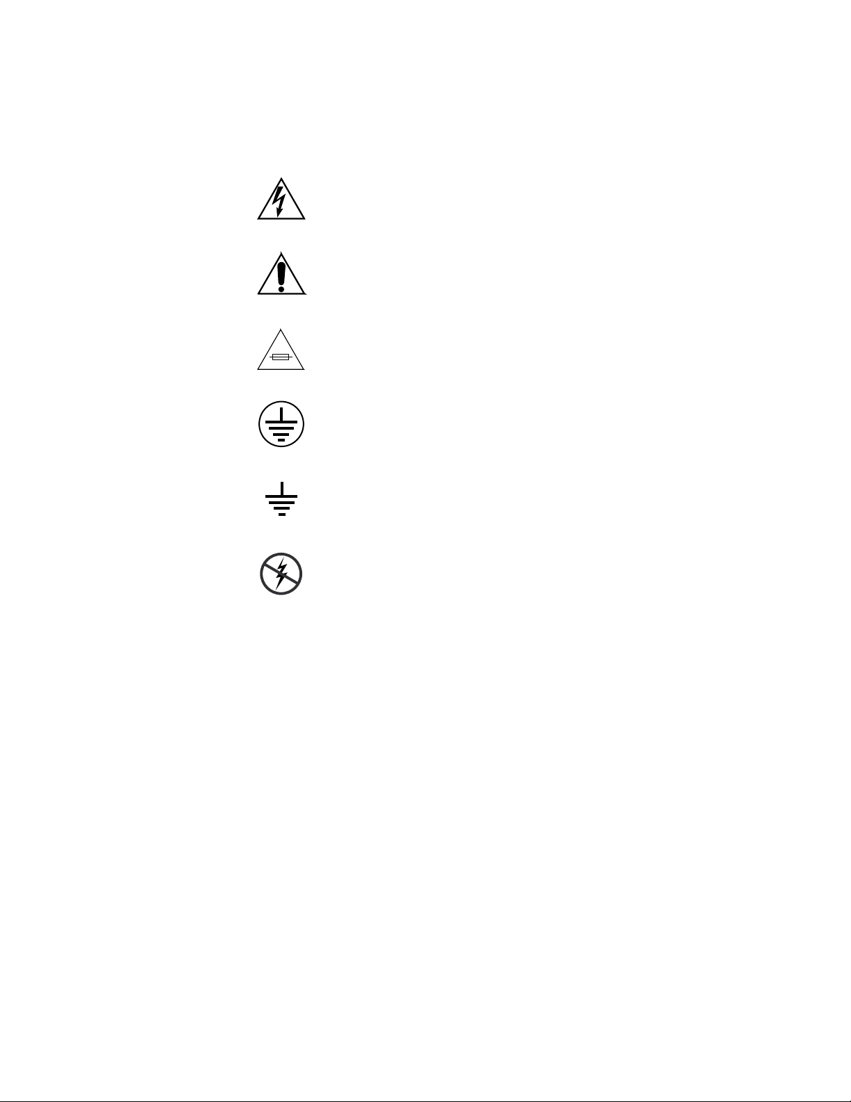
Symbols on the Product
The following symbols may appear on the product:
Indicates that dangerous high voltage is present within the
equipment enclosure that may be of sufficient magnitude to
constitute a risk of electric shock.
Indicates that user, operator or service technician should
refer to product manual(s) for important operating, maintenance, or service instructions.
This is a prompt to note fuse rating when replacing fuse(s).
The fuse referenced in the text must be replaced with one
having the ratings indicated.
Warnings
Identifies a protective grounding terminal which must be
connected to earth ground prior to making any other equipment connections.
Identifies an external protective grounding terminal which
may be connected to earth ground as a supplement to an
internal grounding terminal.
Indicates that static sensitive components are present which
may be damaged by electrostatic discharge. Use anti-static
procedures, equipment and surfaces during servicing.
The following warning statements identify conditions or practices that can
result in personal injury or loss of life.
Dangerous voltage or current may be present
battery (if applicable) before removing protective panels, soldering, or
replacing components.
— Disconnect power and remove
Do not service alone
person capable of rendering first aid and resuscitation is present.
Remove jewelry
and other metallic objects.
Avoid exposed circuitry
circuitry when power is present.
x 7500 Series Instruction Manual
— Do not internally service this product unless another
— Prior to servicing, remove jewelry such as rings, watches,
— Do not touch exposed connections, components or

Use proper power cord
— Use only the power cord supplied or specified for
this product.
Ground product
— Connect the grounding conductor of the power cord to
earth ground.
Operate only with covers and enclosure panels in place
— Do not operate this
product when covers or enclosure panels are removed.
Use correct fuse
— Use only the fuse type and rating specified for this
product.
Use only in dry environment
Use only in non-explosive environment
— Do not operate in wet or damp conditions.
— Do not operate this product in an
explosive atmosphere.
High leakage current may be present
— Earth connection of product is essential
before connecting power.
Dual power supplies may be present
— Be certain to plug each power supply
cord into a separate branch circuit employing a separate service ground.
Disconnect both power supply cords prior to servicing.
Double pole neutral fusing
— Disconnect mains power prior to servicing.
Cautions
Use proper lift points
Avoid mechanical hazards
— Do not use door latches to lift or move equipment.
— Allow all rotating devices to come to a stop before
servicing.
The following caution statements identify conditions or practices that can
result in damage to equipment or other property
Use correct power source
— Do not operate this product from a power sour ce
that applies more than the voltage specified for the product.
Use correct voltage setting
— If this product lacks auto-ranging power supplies, before applying power ensure that the each power supply is set to
match the power source.
Provide proper ventilation
— To prevent product overheating, provide equip-
ment ventilation in accordance with installation instructions.
Use anti-static procedures
— Static sensitive components are present which
may be damaged by electrostatic discharge. Use anti-static procedures,
equipment and surfaces during servicing.
7500 Series Instruction Manual xi

Do not operate with suspected equipment failure
— If you suspect product
damage or equipment failure, have the equipment inspected by qualified
service personnel.
Ensure mains disconnect
— If mains switch is not provided, the power cor d(s)
of this equipment provide the means of disconnection. The socket outlet
must be installed near the equipment and must be easily accessible. Verify
that all mains power is disconnected before installing or removing power
supplies and/or options.
Route cable properly
— Route power cor ds and other cables so that they ar not
likely to be damaged. Properly support heavy cable bundles to avoid connector damage.
Use correct power supply cords
— Power cords for this equipment, if pr ovided,
meet all North American electrical codes. Operation of this equipment at
voltages exceeding 130 VAC requires power supply cords which comply
with NEMA configurations. International power cords, if provided, have
the approval of the country of use.
Use correct replacement battery
— This product may contain batteries. To
reduce the risk of explosion, check polarity and replace only with the same
or equivalent type recommended by manufacturer. Dispose of used batteries according to the manufacturer’s instructions.
Troubleshoot only to board level
— Circuit boards in this product are densely
populated with surface mount technology (SMT) components and application specific integrated circuits (ASICS). As a result, circuit board repair at
the component level is very difficult in the field, if not impossible. For warranty compliance, do not troubleshoot systems beyond the board level.
xii 7500 Series Instruction Manual

Regulatory Notices
Certifications and Compliances
FCC Emission Control
This equipment has been tested and found to comply with the limits for a
Class A digital device, pursuant to Part 15 of the FCC Rules. These limits
are designed to provide reasonable pr otection against harmful interference
when the equipment is operated in a commercial environment. This equipment generates, uses, and can radiate radio frequency energy and, if not
installed and used in accordance with the instruction manual, may cause
harmful interference to radio communications. Operation of this equipment in a residential area is likely to cause harmful interference in which
case the user will be required to correct the interfer ence at his own expense.
Changes or modifications not expressly approved by Grass Valley Group
can affect emission compliance and could void the user’s authority to
operate this equipment.
Canadian EMC Notice of Compliance
This digital apparatus does not exceed the Class A limits for radio noise
emissions from digital apparatus set out in the Radio Interference Regulations of the Canadian Department of Communications.
Le présent appareil numérique n’emet pas de bruits radioélectriques
dépassant les limites applicables aux appareils numeriques de la classe A
préscrites dans le Règlement sur le brouillage radioélectrique édicte par le
ministère des Communications du Canada.
EN55022 Class A Warning
For products that comply with Class A. In a domestic environment this
product may cause radio interference in which case the user may be
required to take adequate measures.
7500 Series Instruction Manual xiii

Canadian Certified Power Cords
Canadian approval includes the products and power cords appr opriate for
use in the North America power network. All other power cords supplied
are approved for the country of use.
Canadian Certified AC Adapter
Canadian approval includes the AC adapters appropriate for use in the
North America power network. All other AC adapters supplied are
approved for the country of use.
Laser Compliance
Laser Safety Requirements
The device used in this product is a Class 1 certified laser product. Operating this product outside specifications or altering from its original design
may result in hazardous radiation exposure, and may be consider ed an act
of modifying or new manufacturing of a laser product under U.S. regulations contained in 21CFR Chapter1, subchapter J or CENELEC regulations
in HD 482 S1. People performing such an act are required by law to recertify and reidentify this product in accordance with provisions of 21CFR
subchapter J for distribution within the U.S.A., and in accordance with
CENELEC HD 482 S1 for distribution within countries using the IEC 825
standard.
Laser Safety
Laser safety in the United States is regulated by the Center for Devices and
Radiological Health (CDRH). The laser safety regulations are published in
the “Laser Product Performance Standard,” Code of Federal Regulation
(CFR), Title 21, Subchapter J.
The international Electrotechnical Commission (IEC) Standard 825, “Radiation of Laser Products, Equipment Classification, Requirements and
User’s Guide,” governs laser products outside the United States. Europe
and member nations of the European Free trade Association fall under the
jurisdiction of the Comite European de Normalization Electrotechnique
(CENELEC).
For the CDRH: The radiant power is detected trough a 7 mm aperture at a
distance of 200 mm from the source focused through a lens with a focal
length of 100 mm.
For IEC compliance: The radiant power is detected trough a 7 mm aperture
at a distance of 100 mm from the source focused through a lens with a focal
length of 100 mm.
xiv 7500 Series Instruction Manual

FCC Emission Limits
Certification
This device complies with Part 15 of the FCC Rules. Operation is subject to
the following two conditions: (1) This device may no cause harmful interference, and (2) this device must accept any interference received,
including interference that may cause undesirable operation. This device
has been tested and found to comply with FCC Part 15 Class B limits for a
digital device when tested with a representative laser-based fiber optical
system that complies with ANSI X3T11 Fiber Channel Standard.
Category Standard Designed/tested for compliance with:
Safety UL1419 Professional Video and Audio Equipment
7500 Series Instruction Manual xv

xvi 7500 Series Instruction Manual
Overview
Introduction
The 7500 Series Routing frames can be controlled by either the Series 7000
Signal Management System or the Encore Control System. The 7500 Series
Routing frames expand the multiformat routing capability of the Series
7000 Signal Management System and are compatible with existing Series
7000 matrices and control panels.
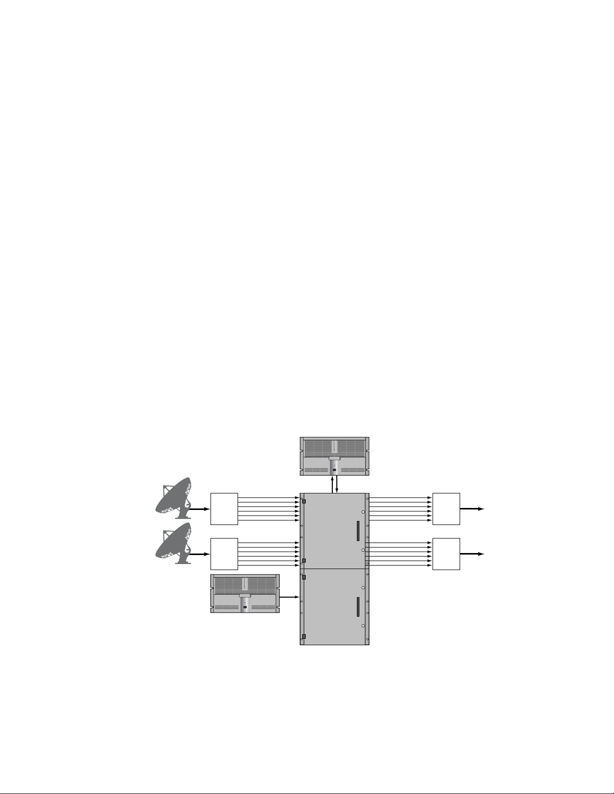
The 7500NB frame is designed to switch digital signals up to 50 Mbps.
Figure 1-1 shows an example of MPEG signal routing using a SMS-
NB512x512
Figure 1-1. 7500NB 512x512 MPEG Signal Routing
Section
1
Incoming
Satellite Feed
Incoming
Satellite Feed
PROFILE XP
Streaming Server
Multiple MPEG
Transport Streams
DMUX
DMUX
PROFILE XP
Time Delay Recorder
SMS-NB512x512
Matrix Frame
0723_00_01
MUX
MUX
Re-Transmission
via Cable or Satellite
Re-Transmission
via Cable or Satellite
7500 Series Instruction Manual 1-1
Section 1 — Overview
Analog
Inputs
SDI Inputs
8900 Series
A-to-D Converters
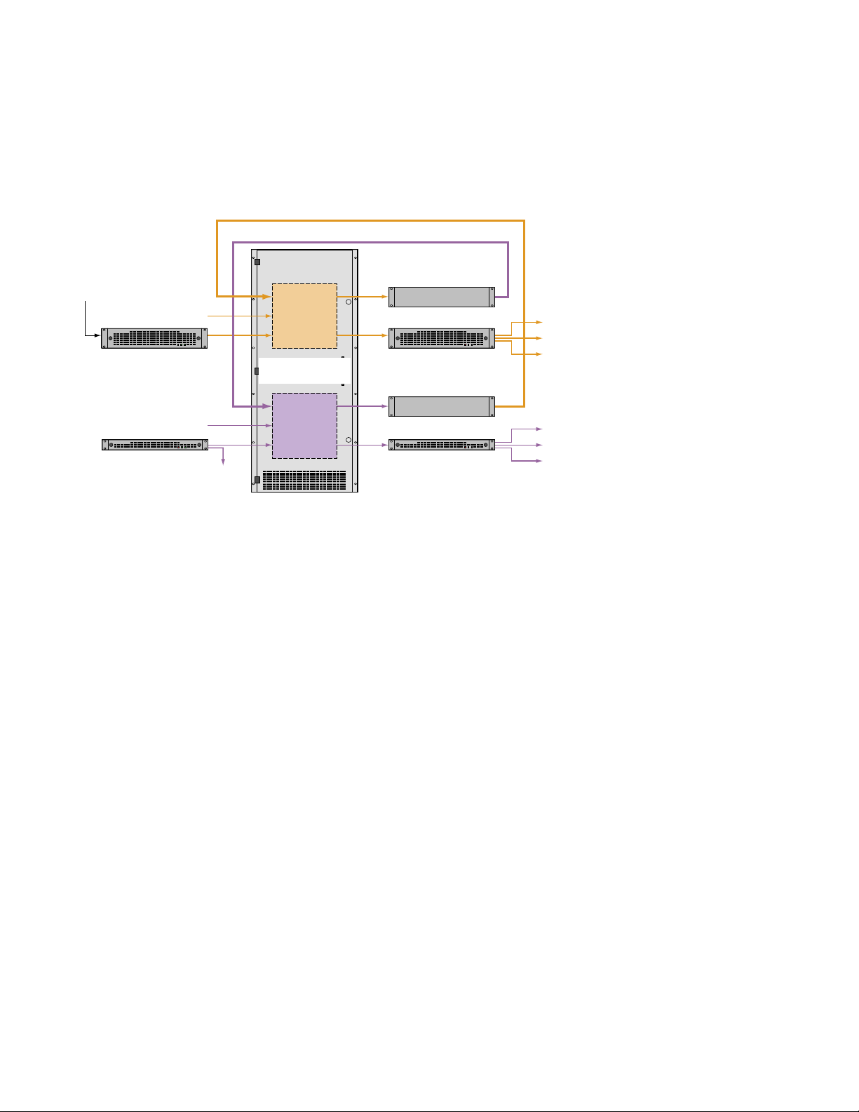
The 7500WB frame is designed to switch signals from 10 Mbps to 1.485
Gbps. Figure 1-2 shows an example of Standard Definition (SD) and High
Definition (HD) signal routing using a 7500WB 256x256.
Figure 1-2. 7500WB 256x256 HD and SD Signal Routing
SD Tie Lines
HD Tie Lines
SD
Operation
7500WB 256x256
Matrix Frame
Up Converter
8900 Series DAs
Profile® XP
Monitor
Master Control
HD Inputs
Monitor
HD
Operation
System Level Architecture
7500NB Architecture
7500NB AES Audio Systems are built around a 256x256, two bay, 12RU
matrix. The 7500NB 256x256 uses one matrix and the 7500NB 512x512 uses
two matrices connected together at the backplanes with expansion connector modules. The 7500NB 1024x1024 uses eight matrices connected
together.
Matrices are populated with crosspoint modules, input modules, output
modules, and matrix controller modules. synchronous and asynchronous
input and output modules are available. Both types of modules can be
placed in the same matrix. The synchronous modules can be configured to
allow an asynchronous signal to be passed through an input or an output.
Down Converter
0723_00_02
2000 Series DAs2000 Series DAs
Profile XP
Monitor
Master Control
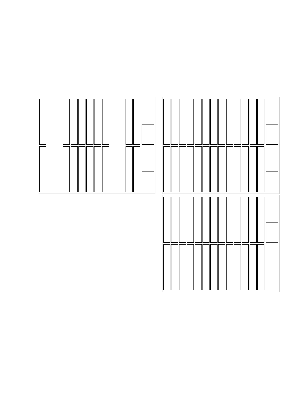
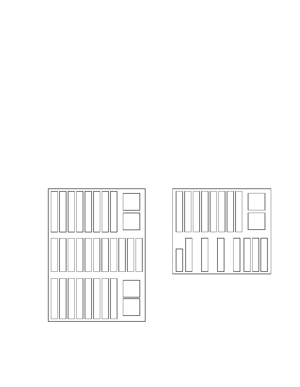
The two bay, 12RU matrix uses four input modules, four output modules,
and eight crosspoint modules for a fully configured 256x256 system. Each
bay of the system contains a slot for a matrix controller and a power supply.
The slot locations for the modules are shown in Figure 1-3. The empty slots
are used for crosspoint modules in expansion systems larger than 256x256.
1-2 7500 Series Instruction Manual
System Level Architecture
Two of the two bay, 12RU matrices are connected using expansion connectors to create a fully configured 512x512 system. The system uses eight
input modules, eight output modules, and thirty-two crosspoint modules
as shown in Figure 1-3. The top bay is always used for inputs 1-128, the
second one for inputs 129-256, the third for 255-384, and the fourth bay is
used for inputs 385-512.
Figure 1-3. 7500NB Module Placement
7500NB 256x256
Inputs 1-64
Inputs 129-192
Xpt Expansion Slot
Xpt Expansion Slot
Xpt Expansion Slot
Xpt Expansion Slot
Outputs 1-64
Xpt (In=1-128, Out=1-64)
Xpt (In=129-256, Out=1-64)
Xpt (In=1-128, Out=129-192)
Outputs 129-192
Xpt (In=129-256, Out=129-192)
Outputs 65-128
Xpt (In=1-128, Out=193-256)
Xpt (In=129-256, Out=193-256)
Xpt (In=1-128, Out=65-128)
Outputs 193-256
Xpt (In=129-256, Out=65-128)
Inputs 65-128
Xpt Expansion Slot
Xpt Expansion Slot
Xpt Expansion Slot
Xpt Expansion Slot
Matrix Controller 1
Inputs 193-256
Matrix Controller 2
Power
Supply
1
Power
Supply
2
7500NB 512x512
Inputs 1-64
Xpt (In=1-128, Out=257-320)
Inputs 129-192
Xpt (In=129-256, Out=257-320)
Inputs 257-320
Xpt (In=257-384, Out=1-64)
Xpt (In=1-128, Out=1-64)
Xpt (In=1-128, Out=385-448)
Xpt (In=129-256, Out=1-64)
Xpt (In=129-256, Out=385-448)
Xpt (In=257-384, Out=129-192)
Xpt (In=257-384, Out=257-320)
Outputs 1-64
Xpt (In=1-128, Out=129-192)
Outputs 129-192
Xpt (In=129-256, Out=129-192)
Outputs 257-320
Xpt (In=257-384, Out=385-448)
Outputs 65-128
Xpt (In=1-128, Out=193-256)
Xpt (In=129-256, Out=193-256)
Xpt (In=257-384, Out=449-512)
Xpt (In=1-128, Out=65-128)
Outputs 193-256
Xpt (In=129-256, Out=65-128)
Outputs 321-384
Xpt (In=257-384, Out=321-384)
Inputs 65-128
Power
Matrix Controller 1
Xpt (In=1-128, Out=449-512)
Xpt (In=1-128, Out=321-384)
Xpt (In=129-256, Out=449-512)
Xpt (In=129-256, Out=321-384)
Xpt (In=257-384, Out=65-128)
Xpt (In=257-384, Out=193-256)
Supply
1
Inputs 193-256
Power
Matrix Controller 2
Supply
2
Inputs 321-384
Power
Matrix Controller 3
Supply
3
Inputs 385-448
Xpt (In=385-512, Out=1-64)
Xpt (In=385-512, Out=129-192)
Outputs 385-448
Xpt (In=385-512, Out=257-320)
Outputs 449-512
Xpt (In=385-512, Out=385-448)
Xpt (In=385-512, Out=449-512)
Xpt (In=385-512, Out=321-384)
Xpt (In=385-512, Out=193-256)
Inputs 449-512
Power
Matrix Controller 4
Xpt (In=385-512, Out=65-128)
Supply
4
7500 Series Instruction Manual 1-3
Section 1 — Overview
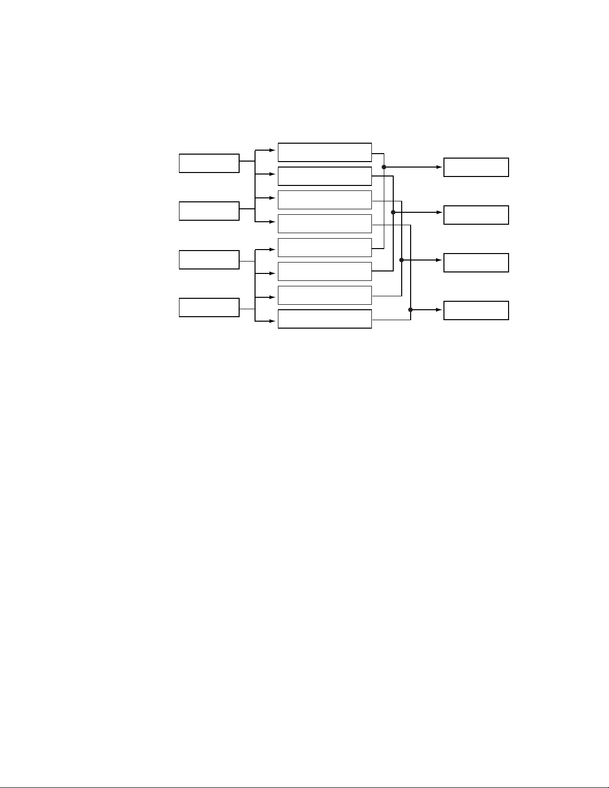
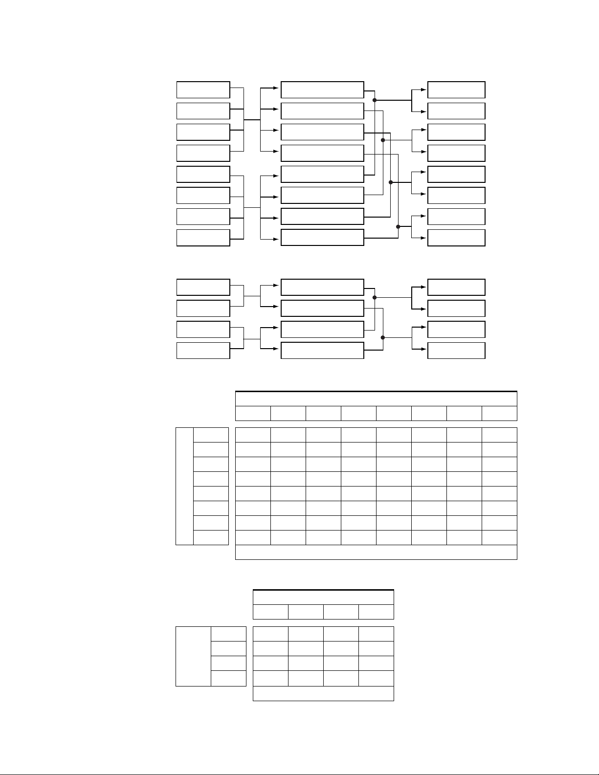
Inputs are routed by the Crosspoint modules to the Output modules to
ensure that all Inputs are available to all Outputs. See Figure 1-4 for the
256x256 signal flow and Figure 1-5 for the 512x512 signal flow.
Figure 1-4. 7500NB 256x256 Signal Flow
Xpt (In=1-128, Out=1-64)
Inputs 1-64
Xpt (In=1-128, Out=65-128)
Xpt (In=1-128, Out=129-192)
Inputs 65-128
Xpt (In=1-128, Out=193-256)
Xpt (In=129-256, Out=1-64)
Inputs 129-192
Xpt (In=129-256, Out=65-128)
Outputs 1-64
Outputs 65-128
Outputs 129-192
Inputs 193-256
Xpt (In=129-256, Out=129-192)
Outputs 193-256
Xpt (In=129-256, Out=193-256)
1-4 7500 Series Instruction Manual
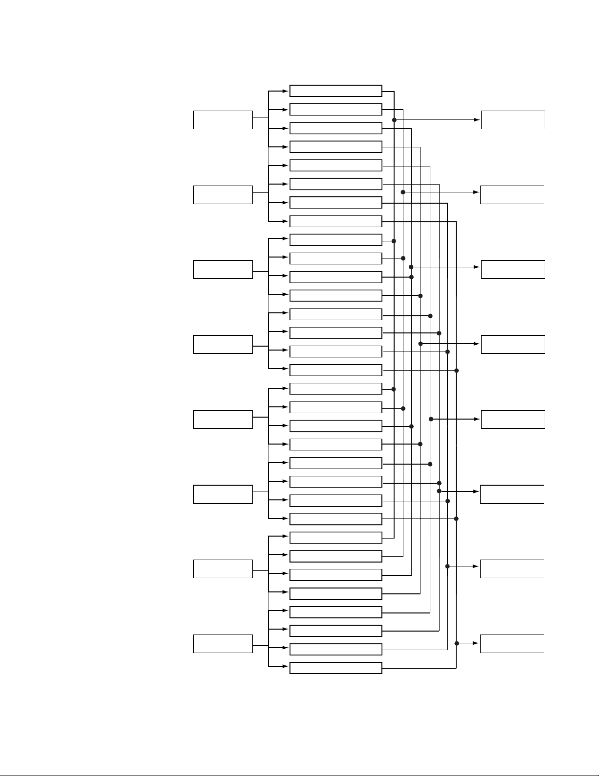
Figure 1-5. 7500NB 512x512Signal Flow
Xpt (In=1-128, Out=1-64)
Xpt (In=1-128, Out=65-128)
Inputs 1-64
Inputs 65-128
Inputs 129-192
Xpt (In=1-128, Out=129-192)
Xpt (In=1-128, Out=193-256)
Xpt (In=1-128, Out=257-320)
Xpt (In=1-128, Out=321-384)
Xpt (In=1-128, Out=385-448)
Xpt (In=1-128, Out=449-512)
Xpt (In=129-256, Out=1-64)
Xpt (In=129-256, Out=65-128)
Xpt (In=129-256, Out=129-192)
System Level Architecture
Outputs 1-64
Outputs 65-128
Outputs 129-192
Inputs 193-256
Inputs 257-320
Inputs 321-384
Inputs 385-448
Xpt (In=129-256, Out=193-256)
Xpt (In=129-256, Out=257-320)
Xpt (In=129-256, Out=321-384)
Xpt (In=129-256, Out=385-448)
Xpt (In=129-256, Out=449-512)
Xpt (In=257-384, Out=1-64)
Xpt (In=257-384, Out=65-128)
Xpt (In=257-384, Out=129-192)
Xpt (In=257-384, Out=193-256)
Xpt (In=257-384, Out=257-320)
Xpt (In=257-384, Out=321-384)
Xpt (In=257-384, Out=385-448)
Xpt (In=257-384, Out=449-512)
Xpt (In=385-512, Out=1-64)
Xpt (In=385-512, Out=65-128)
Xpt (In=385-512, Out=129-192)
Outputs 193-256
Outputs 257-320
Outputs 321-384
Outputs 385-448
Xpt (In=385-512, Out=193-256)
Xpt (In=385-512, Out=257-320)
Xpt (In=385-512, Out=321-384)
Inputs 449-512
Xpt (In=385-512, Out=385-448)
Xpt (In=385-512, Out=449-512)
Outputs 449-512
7500 Series Instruction Manual 1-5
Section 1 — Overview
64 128 192 256 320 384 448 512 576 640 704 768 832 896 960 1024
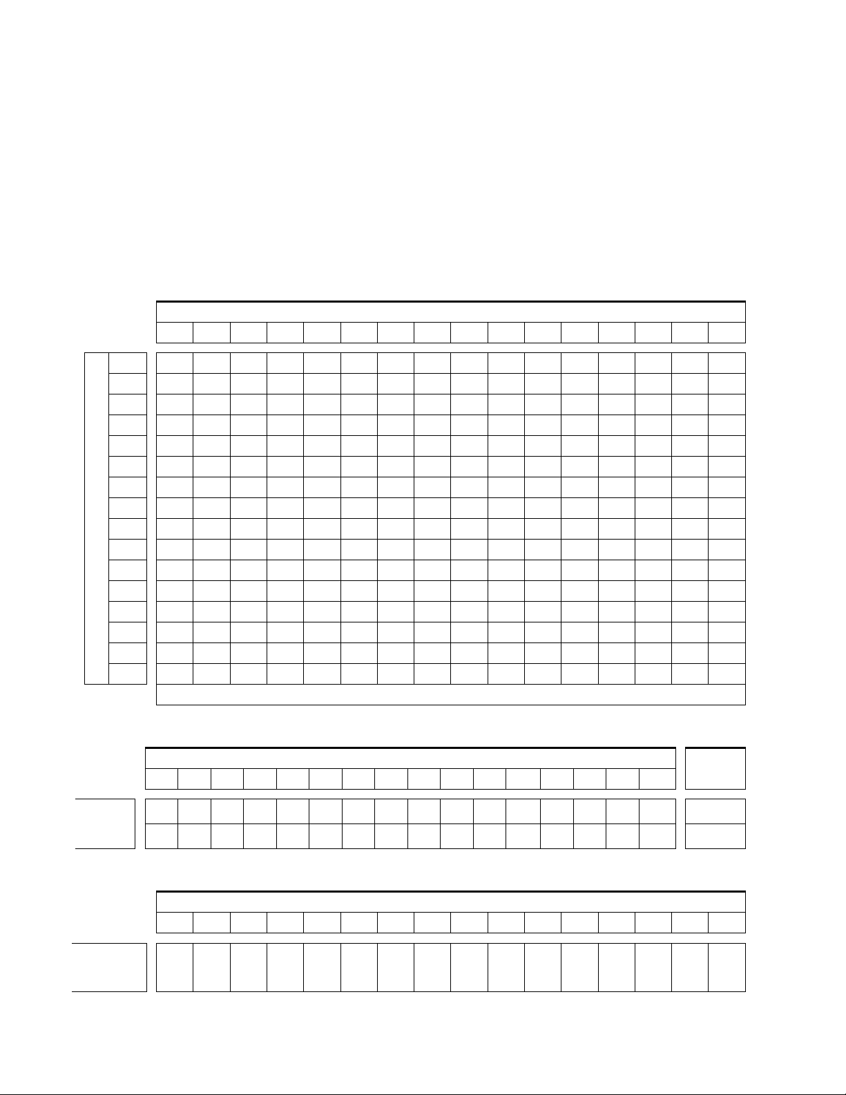
7500NB systems can be expanded in increments of 64 inputs/outputs to as
large as 1024x1024. They are assembled using standard Grass Valley router
frames, distribution amplifiers, Ethernet switches, and in some cases
custom cables. Contact Customer Service for specifications and ordering
details. Table 1-1 shows the number of crosspoint modules required to
create configurations up to 1024x1024.Table 1-2 and Table 1-3 shows the
number of input and output modules needed to create configurations up to
1024x1024.The number of input modules needed is affected by how many
outputs the system contains.
Table 1-1. Required AES 128x64 Crosspoint Modules
Outputs
128
192
256
320
384
448
512
576
Inputs
640
704
768
832
896
960
1024
64
12345678910111213141516
12345678910111213141516
2468101214161820222426283032
2468101214161820222426283032
3691215 18 21 24 27 30 33 36 39 42 45 48
3691215 18 21 24 27 30 33 36 39 42 45 48
481216 20 24 28 32 36 40 44 48 52 56 60 64
481216 20 24 28 32 36 40 44 48 52 56 60 64
5101520253035404550556065707580
5101520253035404550556065707580
6121824303642485460667278849096
6121824303642485460667278849096
714212835424956607077849198105112
714212835424956607077849198105112
81624324048566466808896104112120128
81624324048566466808896104112120128
Crosspoint Modules Required
Table 1-2. Required AES Input Modules
Inputs
64 128 192 256 320 384 448 512 576 640 704 768 832 896 960 1024
Outputs
# of Input
Boards
Required
# of Output
Boards
Required
12345678910111213141516
2468101214161820222426283032 >512
Table 1-3. Required AES Output Modules
Outputs
64 128 192 256 320 384 448 512 576 640 704 768 832 896 960 1024
12345678910111213141516
≤
512
1-6 7500 Series Instruction Manual
7500WB Architecture
The 7500WB 256x256 matrix frame is configured with a Controller module,
two Power Supply modules, eight Input modules, eight Crosspoint modules, eight Output modules, a two-piece backplane, an interconnect and an
optional monitor module. The router has two Controller module slots and
four Power Supply module slots to allow for redundancy. See Figure 1-6.
The 7500WB 128x128 matrix frame is configured with a Controller module,
one Power Supply module, four Input modules, four Crosspoint modules,
four Output modules, a backplane, an interconnect, a DC Distribution
module, and an optional monitor module. The router has two Controller
module slots and two Power Supply module slots to allow for redundancy.
See Figure 1-6.
Inputs are routed by the Crosspoint modules to the Output modules to
ensure that all Inputs are available to all Outputs. See Figure 1-7 and
Figure 1-8 for the signal flow. Table 1-4 shows how many Crosspoint,
Input, and Output modules are needed to create configurations in a
7500WB 256x256 from 32x32 to 256x256. Table 1-5 shows how many Cros-
spoint, Input, and Output modules are needed in a 7500WB 128x128 to
create configurations from 32x32 to 128x128.
System Level Architecture
7500WB 256x256
Input 1-32
Input 65-96
Output 1-32
Xpt (In=1-128, Out=1-64)
Xpt (In=1-128, Out=65-128)
Xpt (In=1-128, Out=129-192)
Input 33-64
Input 97-128
Output 33-64
Figure 1-6. 7500WB Module Placement
Output 65-96
Output 129-160
Xpt (In=129-256, Out=1-64)
Xpt (In=1-128, Out=193-256)
Output 97-128
Output 161-192
Input 129-160
Output 193-224
Xpt (In=129-256, Out=65-128)
Xpt (In=129-256, Out=129-192)
Input 161-192
Output 225-256
Power
Supply
1
Power
Input 193-224
Supply
2
Monitor
Controller
Controller
Xpt (In=129-256, Out=193-256)
Power
Supply
3
Power
Input 225-256
Supply
4
7500WB 128x128
Input 1-32
Input 33-64
Output 1-32
Xpt (In=1-64, Out=1-64)
DC Distribution
Output 33-64
Output 65-96
Xpt (In=1-64, Out=65-128)
Input 65-96
Output 97-128
Xpt (In=65-128, Out=1-64)
Power
Supply
1
Power
Input 97-128
Supply
2
Monitor
Controller
Controller
Xpt (In=65-128, Out=65-128)
7500 Series Instruction Manual 1-7
Section 1 — Overview
Figure 1-7. Signal Flow 7500WB 256x256
Inputs 1-32
Xpt (In=1-128, Out=1-64)
Outputs 1-32
Inputs 33-64
Inputs 65-96
Inputs 97-128
Inputs 129-160
Inputs 161-192
Inputs 193-224
Inputs 225-256
Xpt (In=1-128, Out=65-128)
Xpt (In=1-128, Out=129-192)
Xpt (In=1-128, Out=193-256)
Xpt (In=129-256, Out=1-64)
Xpt (In=129-256, Out=65-128)
Xpt (In=129-256, Out=129-192)
Xpt (In=129-256, Out=193-256)
Figure 1-8. Signal Flow 7500WB 128x128
Inputs 1-32
Inputs 33-64
Inputs 65-96
Inputs 97-128
Xpt (In=1-64, Out=1-64)
Xpt (In=1-64, Out=65-128)
Xpt (In=65-128, Out=1-64)
Xpt (In=65-128, Out=65-128)
Table 1-4. Crosspoint Modules Required for 7500WB 256x256
Outputs 33-64
Outputs 65-96
Outputs 97-128
Outputs 129-160
Outputs 161-192
Outputs 193-224
Outputs 224-256
Outputs 1-32
Outputs 33-64
Outputs 65-96
Outputs 97-128
Outputs (# of Modules)
32 (1) 64 (2) 96 (3) 128 (4) 160 (5) 196 (6) 224 (7) 256 (8)
32 (1)
64 (2)
96 (3)
128 (4)
160 (5)
196 (6)
Inputs (# of Modules)
224 (7)
256 (8)
11223344
11223344
11223344
11223344
22446688
22446688
22446688
22446688
Crosspoint Modules Required
Table 1-5. Crosspoint Modules Required for 7500WB 128x128
Outputs (# of Modules)
32 (1) 64 (2) 96 (3) 128 (4)
32 (1)
64 (2)
96 (3)
Inputs
128 (4)
(# of Modules)
1122
1122
2244
2244
Crosspoint Modules Required
1-8 7500 Series Instruction Manual
Installation
Frame Installation
The 7500 Series matrices are installed in a standard 483 mm (19-inch) rack.
Rear frame support is not required.
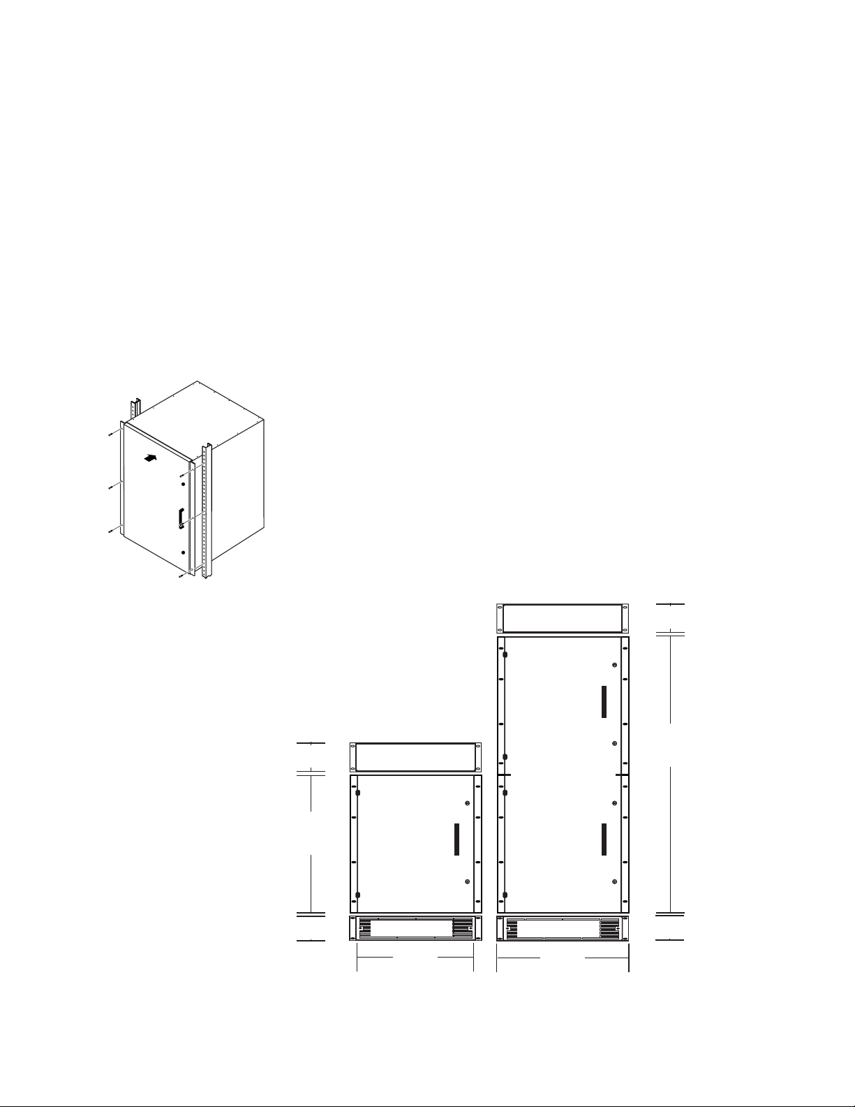
7500 NB Frame Installation
The 7500NB 256x256 occupies 12 rack-units. Cooling is by vertical airflow
using an external fan set. The 7500NB 512x512 is two 7500NB 256x256
frames connected by an Expansion module set. The 7500NB 512x512 occupies 24 rack-units. See Figure 2-2.
Section
2
Figure 2-1. Rack Mount
Figure 2-2. NB Rack Installation Front View
2 RU
89 mm/3.55 in.
12 RU
534 mm
21 in.
2 RU
89 mm/3.55 in.
Exhaust Unit
7500NB 256x256
Frame
Intake/Fan Unit
438 mm
17.25 in.
Exhaust Unit
7500NB 512x512
Frame
Intake/Fan Unit
483 mm
19 in.
2 RU
89 mm/3.55 in.
24 RU
1067 mm
42 in.
2 RU
89 mm/3.55 in.
7500 Series Instruction Manual 2-1
Section 2 — Installation
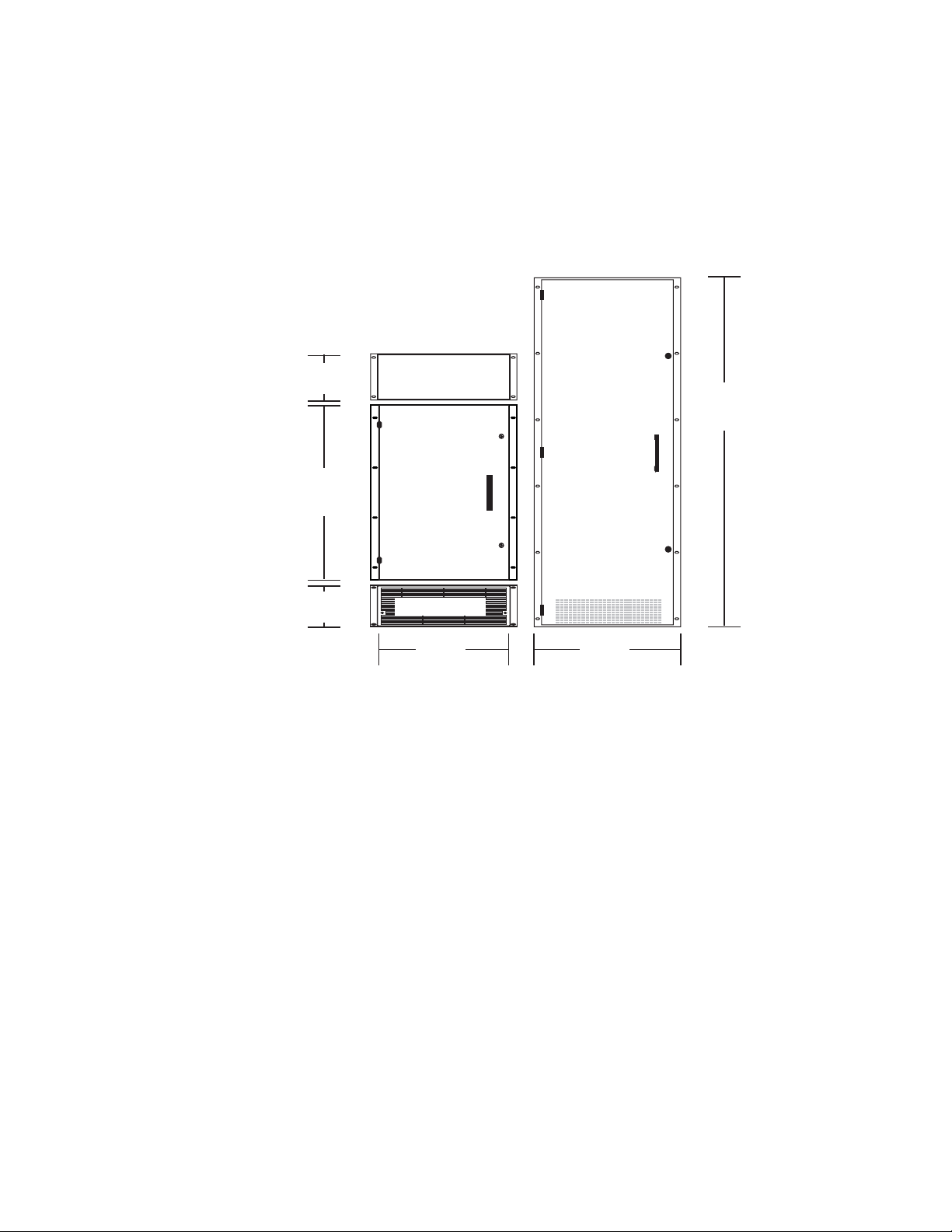
7500 WB Frame Installation
The 7500WB 256x256 router occupies 25 rack-units. Cooling is by vertical
airflow using a fan mounted inside the top of the frame and an air filter on
the front door . The 7500WB 128x128 r outer occupies 13 rack-units. Cooling
is by vertical airflow using an external fan set. See Figure 2-3.
Figure 2-3. WB Rack Installation Front View
7500WB 256x256
Frame
3 RU
134 mm/5.25 in.
13 RU
578 mm
22.72 in.
Exhaust Unit
25 RU
1110 mm
43.75 in.
7500WB 128x128
Frame
3 RU
134 mm/5.25 in.
Intake/Fan Unit
438 mm
17.25 in.
483 mm
19 in.
2-2 7500 Series Instruction Manual
Module Installation
All the modules are vertically oriented in the frames, and edge guides aid
insertion and removal.
CAUTION It is critical that the modules be placed in the proper slot and oriented cor-
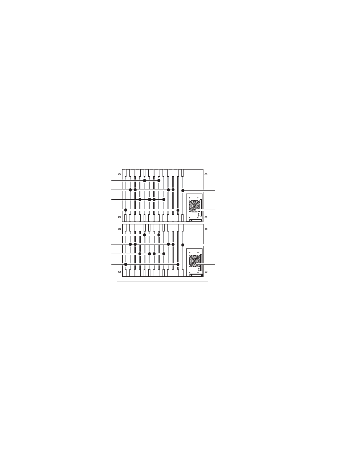
7500NB Module Placement
7500NB modules are oriented in the frame with the front (populated) side
facing to the right. See Figure 2-4.
Figure 2-4. 7500NB Module Configuration and Alignment
Output Modules
Crosspoint Expansion Modules
Crosspoint Modules
Input Modules
rectly to prevent bent pins.
DC OK
AC PRESENT
Module Installation
Controller Modules
Power Supply Modules
Output Modules
Crosspoint Expansion Modules
Crosspoint Modules
Input Modules
AC PRESENT
Controller Modules
DC OK
Power Supply Modules
7500 Series Instruction Manual 2-3
Section 2 — Installation
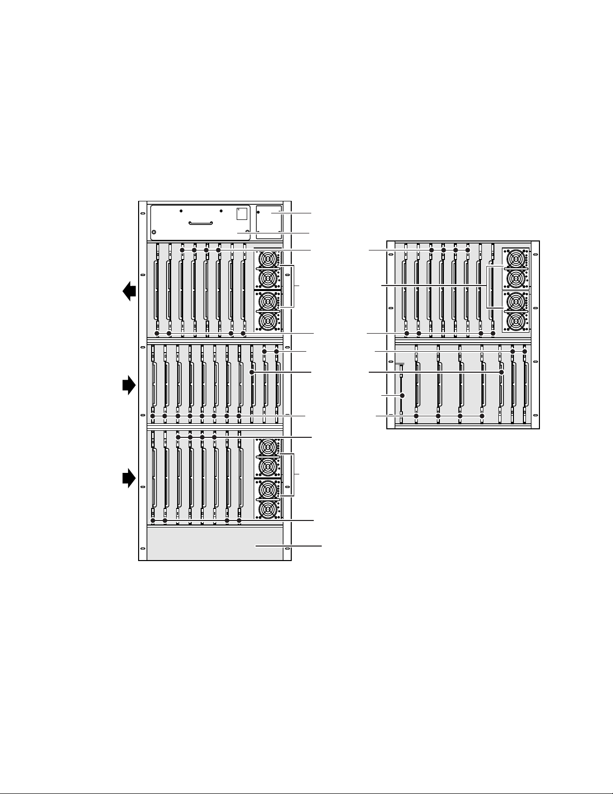
7500WB Module Placement
7500WB 256X256
In the top row of the 7500WB, Input and Output modules are oriented in
the frame with the front (populated) side facing to the left. The other rows
of modules are orientated in the frame with the front (populated) side
facing to the right. See Figure 2-5.
Figure 2-5. 7500WB Module Configuration and Alignment
WARNING
ROTATING
FAN BLADES
PULL OUT
1/2 INCH
AND WAIT
30 SECONDS
BEFORE
REMOVING
Thermal Control
Module Cover
Exhaust Fan Unit
7500WB 128X128
In this row all
Input and Output
modules are
orientated with
fronts to the left.
In this row all
modules are
orientated with
fronts to the right
In this row all
Input and Output
modules are
orientated with
fronts to the right.
All Power Supply
modules are
orientated with the
tops to the left.
100%
20 40 60 80
DCG
ACG
VADJ
100%
20 40 60 80
DCG
ACG
VADJ
Output Modules
Power Supply Modules
Input Modules
Controller Modules
Monitor Module
DC Distribution Module
Crosspoint Modules
100%
20 40 60 80
DCG
ACG
VADJ
100%
20 40 60 80
DCG
ACG
VADJ
Output Modules
Power Supply Modules
Input Modules
Air Intake
100%
20 40 60 80
DCG
ACG
VADJ
100%
20 40 60 80
DCG
ACG
VADJ
0528_01_16
2-4 7500 Series Instruction Manual
 Loading...