

Page 1

Reference
3.1software release
071-0440-00
FIRST PRINTING: DECEMBER 1997
REVISED PRINTING: OCTOBER 1998
KRYSTAL 4300
DIGITAL PICTURE MANIPULATOR
Page 2

Contacting Grass Valley Group
Region Voice Fax Address Web Site
North America (800) 547-8949
530-478-4148
Pacific Operations +852-2585-6688
Support: 852-2585-6579
U.K., Europe, Asia, Middle East +44 1753 218 777 +44 1753 218 757
France +33 1 45 29 73 00
Germany +49 221 1791 234 +49 221 1791 235
Copyright © Grass Valley Group. All rights reserved.
This document may not be copied, in whole or in part, or otherwise reproduced, except as specifically
permitted under U.S. copyright law, without the prior written consent of Grass Valley Group, P.O. Box
599000, Nevada City, CA 95959-7900 USA. GRASS VALLEY GROUP is a registered trademark and
Grass Valley is a trademark of Grass Valley Group. All registered trademarks and trademarks are property of their respective holders. Grass Valley Group products are covered by U.S. and foreign patents,
issued and pending. Product options and specifications subject to change without notice. The information in this manual is furnished for informational use only, is subject to change without notice, and
should not be construed as a commitment by Grass Valley Group. Grass Valley Group assumes no responsibility or liability for any errors or inaccuracies that may appear in this publication.
(530) 478-3347 Grass Valley Group
+852-2802-2996
P.O. Box 599000
Nevada City, CA 95959-7900
USA
www.grassvalleygroup.com
Page 3

Contents
Preface
About This Manual . . . . . . . . . . . . . . . . . . . . . . . . . . . . . . . . . . . . . . . . . . . . . . . . . . . . xi
Documentation Set . . . . . . . . . . . . . . . . . . . . . . . . . . . . . . . . . . . . . . . . . . . . . . . . . . xi
Conventions Used In This Manual. . . . . . . . . . . . . . . . . . . . . . . . . . . . . . . . . . . . . . . xii
Button References . . . . . . . . . . . . . . . . . . . . . . . . . . . . . . . . . . . . . . . . . . . . . . . . . . . xii
Menu Display References. . . . . . . . . . . . . . . . . . . . . . . . . . . . . . . . . . . . . . . . . . . . . xii
Section 1 — System Overview
General Description . . . . . . . . . . . . . . . . . . . . . . . . . . . . . . . . . . . . . . . . . . . . . . . . . . 1-1
Standard Option Package Features. . . . . . . . . . . . . . . . . . . . . . . . . . . . . . . . . . . . 1-1
Fully Optioned Channel Packages . . . . . . . . . . . . . . . . . . . . . . . . . . . . . . . . . . . . 1-2
Optional Features . . . . . . . . . . . . . . . . . . . . . . . . . . . . . . . . . . . . . . . . . . . . . . . . . . 1-3
Feature Packaging Changes . . . . . . . . . . . . . . . . . . . . . . . . . . . . . . . . . . . . . . . . . . 1-3
Physical Description . . . . . . . . . . . . . . . . . . . . . . . . . . . . . . . . . . . . . . . . . . . . . . . . . . 1-3
Major Components . . . . . . . . . . . . . . . . . . . . . . . . . . . . . . . . . . . . . . . . . . . . . . . . . 1-3
System Control. . . . . . . . . . . . . . . . . . . . . . . . . . . . . . . . . . . . . . . . . . . . . . . . . . . . . 1-8
Control Panel . . . . . . . . . . . . . . . . . . . . . . . . . . . . . . . . . . . . . . . . . . . . . . . . . . . . . . 1-8
Video Processor Frame . . . . . . . . . . . . . . . . . . . . . . . . . . . . . . . . . . . . . . . . . . . . . 1-10
System Controller Frame . . . . . . . . . . . . . . . . . . . . . . . . . . . . . . . . . . . . . . . . . . . 1-12
Large System Controller . . . . . . . . . . . . . . . . . . . . . . . . . . . . . . . . . . . . . . . . . . 1-12
Small System Controller . . . . . . . . . . . . . . . . . . . . . . . . . . . . . . . . . . . . . . . . . . 1-14
Module Descriptions. . . . . . . . . . . . . . . . . . . . . . . . . . . . . . . . . . . . . . . . . . . . . . . 1-15
Module and Mezzanine Part Numbers . . . . . . . . . . . . . . . . . . . . . . . . . . . . . . . 1-17
Facility Examples. . . . . . . . . . . . . . . . . . . . . . . . . . . . . . . . . . . . . . . . . . . . . . . . . . 1-18
Single Channel Krystal Facility . . . . . . . . . . . . . . . . . . . . . . . . . . . . . . . . . . . . . . 1-18
Two Channel, Two User Krystal Facility . . . . . . . . . . . . . . . . . . . . . . . . . . . . . . 1-20
Eight Channel Four User Krystal Facility . . . . . . . . . . . . . . . . . . . . . . . . . . . . . 1-22
Integrated Model 2200-2i Switcher . . . . . . . . . . . . . . . . . . . . . . . . . . . . . . . . . . . 1-23
Section 2 — Controls
Introduction . . . . . . . . . . . . . . . . . . . . . . . . . . . . . . . . . . . . . . . . . . . . . . . . . . . . . . . . . 2-1
Control Panel . . . . . . . . . . . . . . . . . . . . . . . . . . . . . . . . . . . . . . . . . . . . . . . . . . . . . . . . 2-1
Upper Panel Area . . . . . . . . . . . . . . . . . . . . . . . . . . . . . . . . . . . . . . . . . . . . . . . . . . 2-2
Lower Panel Area . . . . . . . . . . . . . . . . . . . . . . . . . . . . . . . . . . . . . . . . . . . . . . . . . . 2-2
Menu Display. . . . . . . . . . . . . . . . . . . . . . . . . . . . . . . . . . . . . . . . . . . . . . . . . . . . . . 2-3
Soft Buttons. . . . . . . . . . . . . . . . . . . . . . . . . . . . . . . . . . . . . . . . . . . . . . . . . . . . . . . . 2-4
Exit Button . . . . . . . . . . . . . . . . . . . . . . . . . . . . . . . . . . . . . . . . . . . . . . . . . . . . . . . . 2-4
Soft Knob And Transfer Buttons . . . . . . . . . . . . . . . . . . . . . . . . . . . . . . . . . . . . . . 2-5
Krystal 4300 Reference iii
Page 4

Contents
Illuminated Button Tally Information . . . . . . . . . . . . . . . . . . . . . . . . . . . . . . . . . . 2-5
Double-Press Functions . . . . . . . . . . . . . . . . . . . . . . . . . . . . . . . . . . . . . . . . . . . . . . 2-6
DPOP Functions . . . . . . . . . . . . . . . . . . . . . . . . . . . . . . . . . . . . . . . . . . . . . . . . . . . . 2-7
Top Menus . . . . . . . . . . . . . . . . . . . . . . . . . . . . . . . . . . . . . . . . . . . . . . . . . . . . . . . . . 2-7
System Setup . . . . . . . . . . . . . . . . . . . . . . . . . . . . . . . . . . . . . . . . . . . . . . . . . . . . . 2-7
User Tools. . . . . . . . . . . . . . . . . . . . . . . . . . . . . . . . . . . . . . . . . . . . . . . . . . . . . . . . 2-7
File Operations. . . . . . . . . . . . . . . . . . . . . . . . . . . . . . . . . . . . . . . . . . . . . . . . . . . . 2-8
Macro. . . . . . . . . . . . . . . . . . . . . . . . . . . . . . . . . . . . . . . . . . . . . . . . . . . . . . . . . . . . 2-8
Run Control . . . . . . . . . . . . . . . . . . . . . . . . . . . . . . . . . . . . . . . . . . . . . . . . . . . . . . 2-8
Picture . . . . . . . . . . . . . . . . . . . . . . . . . . . . . . . . . . . . . . . . . . . . . . . . . . . . . . . . . . . 2-8
Picture Frame Menu . . . . . . . . . . . . . . . . . . . . . . . . . . . . . . . . . . . . . . . . . . . . . . . 2-8
Key/Stencil Menu . . . . . . . . . . . . . . . . . . . . . . . . . . . . . . . . . . . . . . . . . . . . . . . . . 2-8
View Menu . . . . . . . . . . . . . . . . . . . . . . . . . . . . . . . . . . . . . . . . . . . . . . . . . . . . . . . 2-8
Input/Output Menu . . . . . . . . . . . . . . . . . . . . . . . . . . . . . . . . . . . . . . . . . . . . . . . 2-8
User Assist Area . . . . . . . . . . . . . . . . . . . . . . . . . . . . . . . . . . . . . . . . . . . . . . . . . . . . . . 2-9
Macro/Enable/Deleg Area. . . . . . . . . . . . . . . . . . . . . . . . . . . . . . . . . . . . . . . . . . . . 2-10
Macro Buttons . . . . . . . . . . . . . . . . . . . . . . . . . . . . . . . . . . . . . . . . . . . . . . . . . . . . . 2-10
Channel Enable Buttons. . . . . . . . . . . . . . . . . . . . . . . . . . . . . . . . . . . . . . . . . . . . . 2-10
Channel Delegation Buttons . . . . . . . . . . . . . . . . . . . . . . . . . . . . . . . . . . . . . . . . . 2-11
Clipboard Operations Area. . . . . . . . . . . . . . . . . . . . . . . . . . . . . . . . . . . . . . . . . . . . 2-11
Effect Edit Area. . . . . . . . . . . . . . . . . . . . . . . . . . . . . . . . . . . . . . . . . . . . . . . . . . . . . . 2-13
Keypad . . . . . . . . . . . . . . . . . . . . . . . . . . . . . . . . . . . . . . . . . . . . . . . . . . . . . . . . . . . . . 2-15
Numeric Entry. . . . . . . . . . . . . . . . . . . . . . . . . . . . . . . . . . . . . . . . . . . . . . . . . . . . . 2-15
Transfer Buttons . . . . . . . . . . . . . . . . . . . . . . . . . . . . . . . . . . . . . . . . . . . . . . . . . . . 2-15
E-MEM Area . . . . . . . . . . . . . . . . . . . . . . . . . . . . . . . . . . . . . . . . . . . . . . . . . . . . . . . . 2-16
Mode Area . . . . . . . . . . . . . . . . . . . . . . . . . . . . . . . . . . . . . . . . . . . . . . . . . . . . . . . . . . 2-17
Override Area . . . . . . . . . . . . . . . . . . . . . . . . . . . . . . . . . . . . . . . . . . . . . . . . . . . . . . . 2-17
Run Area . . . . . . . . . . . . . . . . . . . . . . . . . . . . . . . . . . . . . . . . . . . . . . . . . . . . . . . . . . . 2-18
Lever Arm . . . . . . . . . . . . . . . . . . . . . . . . . . . . . . . . . . . . . . . . . . . . . . . . . . . . . . . . 2-18
Bar Graph Indicator . . . . . . . . . . . . . . . . . . . . . . . . . . . . . . . . . . . . . . . . . . . . . . . . 2-18
Transform Area. . . . . . . . . . . . . . . . . . . . . . . . . . . . . . . . . . . . . . . . . . . . . . . . . . . . . . 2-20
Joystick . . . . . . . . . . . . . . . . . . . . . . . . . . . . . . . . . . . . . . . . . . . . . . . . . . . . . . . . . . . 2-22
Turbo Button . . . . . . . . . . . . . . . . . . . . . . . . . . . . . . . . . . . . . . . . . . . . . . . . . . . . 2-22
Floppy Disk Drive . . . . . . . . . . . . . . . . . . . . . . . . . . . . . . . . . . . . . . . . . . . . . . . . . . . 2-25
Section 3 — System Setup Menu
Introduction. . . . . . . . . . . . . . . . . . . . . . . . . . . . . . . . . . . . . . . . . . . . . . . . . . . . . . . . . . 3-1
Resource Acquisition Menu . . . . . . . . . . . . . . . . . . . . . . . . . . . . . . . . . . . . . . . . . . . . 3-2
Effect Manager Resource Acquisition . . . . . . . . . . . . . . . . . . . . . . . . . . . . . . . . 3-2
Channel Resource Acquisition . . . . . . . . . . . . . . . . . . . . . . . . . . . . . . . . . . . . . . 3-3
External Control Preferences Menu. . . . . . . . . . . . . . . . . . . . . . . . . . . . . . . . . . . . . . 3-4
Serial Ports Preferences . . . . . . . . . . . . . . . . . . . . . . . . . . . . . . . . . . . . . . . . . . . . 3-4
GPI Preferences . . . . . . . . . . . . . . . . . . . . . . . . . . . . . . . . . . . . . . . . . . . . . . . . . . . 3-5
Defaults Preferences . . . . . . . . . . . . . . . . . . . . . . . . . . . . . . . . . . . . . . . . . . . . . . . 3-7
Run Preferences Menu. . . . . . . . . . . . . . . . . . . . . . . . . . . . . . . . . . . . . . . . . . . . . . . . . 3-8
Panel Configuration Menu . . . . . . . . . . . . . . . . . . . . . . . . . . . . . . . . . . . . . . . . . . . . . 3-9
System Configuration Menu. . . . . . . . . . . . . . . . . . . . . . . . . . . . . . . . . . . . . . . . . . . 3-10
Section 4 — User Tools Menu
Introduction. . . . . . . . . . . . . . . . . . . . . . . . . . . . . . . . . . . . . . . . . . . . . . . . . . . . . . . . . . 4-1
iv Krystal 4300 Reference
Page 5

Contents
Source Memory Menu . . . . . . . . . . . . . . . . . . . . . . . . . . . . . . . . . . . . . . . . . . . . . . . . 4-2
Work Buffer Preferences Menu. . . . . . . . . . . . . . . . . . . . . . . . . . . . . . . . . . . . . . . . . 4-4
Display Options Menu . . . . . . . . . . . . . . . . . . . . . . . . . . . . . . . . . . . . . . . . . . . . . . . . 4-6
Panel Preferences Menu. . . . . . . . . . . . . . . . . . . . . . . . . . . . . . . . . . . . . . . . . . . . . . . 4-7
Edit Enable Function. . . . . . . . . . . . . . . . . . . . . . . . . . . . . . . . . . . . . . . . . . . . . . . . . . 4-8
Section 5 — File Operations/Macro Menus
Introduction . . . . . . . . . . . . . . . . . . . . . . . . . . . . . . . . . . . . . . . . . . . . . . . . . . . . . . . . . 5-1
File Operations Menu. . . . . . . . . . . . . . . . . . . . . . . . . . . . . . . . . . . . . . . . . . . . . . . . . 5-1
Saving and Loading Files . . . . . . . . . . . . . . . . . . . . . . . . . . . . . . . . . . . . . . . . . . . . 5-1
Disk Manager Menu . . . . . . . . . . . . . . . . . . . . . . . . . . . . . . . . . . . . . . . . . . . . . . . . 5-4
Register Operations Menu . . . . . . . . . . . . . . . . . . . . . . . . . . . . . . . . . . . . . . . . . . . 5-5
Copy. . . . . . . . . . . . . . . . . . . . . . . . . . . . . . . . . . . . . . . . . . . . . . . . . . . . . . . . . . . . 5-5
Swap. . . . . . . . . . . . . . . . . . . . . . . . . . . . . . . . . . . . . . . . . . . . . . . . . . . . . . . . . . . . 5-6
Erase. . . . . . . . . . . . . . . . . . . . . . . . . . . . . . . . . . . . . . . . . . . . . . . . . . . . . . . . . . . . 5-6
Append . . . . . . . . . . . . . . . . . . . . . . . . . . . . . . . . . . . . . . . . . . . . . . . . . . . . . . . . . 5-6
Move . . . . . . . . . . . . . . . . . . . . . . . . . . . . . . . . . . . . . . . . . . . . . . . . . . . . . . . . . . . 5-7
Channel Operations Menu. . . . . . . . . . . . . . . . . . . . . . . . . . . . . . . . . . . . . . . . . . . 5-8
Copy. . . . . . . . . . . . . . . . . . . . . . . . . . . . . . . . . . . . . . . . . . . . . . . . . . . . . . . . . . . . 5-8
Swap. . . . . . . . . . . . . . . . . . . . . . . . . . . . . . . . . . . . . . . . . . . . . . . . . . . . . . . . . . . . 5-9
Delete . . . . . . . . . . . . . . . . . . . . . . . . . . . . . . . . . . . . . . . . . . . . . . . . . . . . . . . . . . 5-10
Move . . . . . . . . . . . . . . . . . . . . . . . . . . . . . . . . . . . . . . . . . . . . . . . . . . . . . . . . . . 5-10
Name Effect . . . . . . . . . . . . . . . . . . . . . . . . . . . . . . . . . . . . . . . . . . . . . . . . . . . . . . 5-11
Macro Control Menu . . . . . . . . . . . . . . . . . . . . . . . . . . . . . . . . . . . . . . . . . . . . . . . . 5-12
Macro Record . . . . . . . . . . . . . . . . . . . . . . . . . . . . . . . . . . . . . . . . . . . . . . . . . . . . . 5-12
Macro Play . . . . . . . . . . . . . . . . . . . . . . . . . . . . . . . . . . . . . . . . . . . . . . . . . . . . . . . 5-13
Section 6 — Run Control Menu
Introduction . . . . . . . . . . . . . . . . . . . . . . . . . . . . . . . . . . . . . . . . . . . . . . . . . . . . . . . . . 6-1
Path Control Menu . . . . . . . . . . . . . . . . . . . . . . . . . . . . . . . . . . . . . . . . . . . . . . . . . . . 6-2
Transformation Path Control Menus . . . . . . . . . . . . . . . . . . . . . . . . . . . . . . . . . . 6-4
All Transform Paths Menu . . . . . . . . . . . . . . . . . . . . . . . . . . . . . . . . . . . . . . . . . 6-6
Spin Path Control Menu. . . . . . . . . . . . . . . . . . . . . . . . . . . . . . . . . . . . . . . . . . . . . 6-7
Non-Transformation Path Control Menus. . . . . . . . . . . . . . . . . . . . . . . . . . . . . . 6-8
Matte Path Control Menus. . . . . . . . . . . . . . . . . . . . . . . . . . . . . . . . . . . . . . . . . . . 6-9
Multiple Parameter Path Menus . . . . . . . . . . . . . . . . . . . . . . . . . . . . . . . . . . . . . 6-10
Pause Control Menu . . . . . . . . . . . . . . . . . . . . . . . . . . . . . . . . . . . . . . . . . . . . . . . . . 6-11
Loop Control Menu . . . . . . . . . . . . . . . . . . . . . . . . . . . . . . . . . . . . . . . . . . . . . . . . . 6-12
Section 7 — Picture Menu
Introduction . . . . . . . . . . . . . . . . . . . . . . . . . . . . . . . . . . . . . . . . . . . . . . . . . . . . . . . . . 7-1
Pseudo Color Menu . . . . . . . . . . . . . . . . . . . . . . . . . . . . . . . . . . . . . . . . . . . . . . . . . . 7-2
Color Correction . . . . . . . . . . . . . . . . . . . . . . . . . . . . . . . . . . . . . . . . . . . . . . . . . . . 7-3
Posterization/Solarization Appearance. . . . . . . . . . . . . . . . . . . . . . . . . . . . . . . . 7-5
Color Modulation/Appearance . . . . . . . . . . . . . . . . . . . . . . . . . . . . . . . . . . . . . . 7-6
Hue Modulation/Appearance. . . . . . . . . . . . . . . . . . . . . . . . . . . . . . . . . . . . . . . . 7-7
Pseudo Color Mask . . . . . . . . . . . . . . . . . . . . . . . . . . . . . . . . . . . . . . . . . . . . . . . . . 7-8
Pseudo Color Path Menu . . . . . . . . . . . . . . . . . . . . . . . . . . . . . . . . . . . . . . . . . . . . 7-9
Picture Opacity Menu. . . . . . . . . . . . . . . . . . . . . . . . . . . . . . . . . . . . . . . . . . . . . . . . 7-10
Krystal 4300 Reference v
Page 6

Contents
Final Picture Opacity . . . . . . . . . . . . . . . . . . . . . . . . . . . . . . . . . . . . . . . . . . . . . . . 7-10
Picture Opacity Path Menu . . . . . . . . . . . . . . . . . . . . . . . . . . . . . . . . . . . . . . . . . . 7-11
Defocus/Glow Menu. . . . . . . . . . . . . . . . . . . . . . . . . . . . . . . . . . . . . . . . . . . . . . . . . 7-12
Defocus/Appearance . . . . . . . . . . . . . . . . . . . . . . . . . . . . . . . . . . . . . . . . . . . . . . . 7-13
Defocus/NAM . . . . . . . . . . . . . . . . . . . . . . . . . . . . . . . . . . . . . . . . . . . . . . . . . . . . 7-14
Defocus/Boundary Replicate . . . . . . . . . . . . . . . . . . . . . . . . . . . . . . . . . . . . . . . . 7-15
Defocus/Key Adjust. . . . . . . . . . . . . . . . . . . . . . . . . . . . . . . . . . . . . . . . . . . . . . . . 7-16
Defocus/Mask. . . . . . . . . . . . . . . . . . . . . . . . . . . . . . . . . . . . . . . . . . . . . . . . . . . . . 7-17
Glow/Appearance . . . . . . . . . . . . . . . . . . . . . . . . . . . . . . . . . . . . . . . . . . . . . . . . . 7-18
Glow/Matte. . . . . . . . . . . . . . . . . . . . . . . . . . . . . . . . . . . . . . . . . . . . . . . . . . . . . . . 7-19
Defocus/Glow Path Menu . . . . . . . . . . . . . . . . . . . . . . . . . . . . . . . . . . . . . . . . . . 7-20
Mosaic Menu. . . . . . . . . . . . . . . . . . . . . . . . . . . . . . . . . . . . . . . . . . . . . . . . . . . . . . . . 7-21
Mosaic Path Menu . . . . . . . . . . . . . . . . . . . . . . . . . . . . . . . . . . . . . . . . . . . . . . . . . 7-22
Input Recursive Menu . . . . . . . . . . . . . . . . . . . . . . . . . . . . . . . . . . . . . . . . . . . . . . . . 7-23
Freeze/Appearance . . . . . . . . . . . . . . . . . . . . . . . . . . . . . . . . . . . . . . . . . . . . . . . . 7-24
Motion Decay/Appearance. . . . . . . . . . . . . . . . . . . . . . . . . . . . . . . . . . . . . . . . . . 7-25
Timing. . . . . . . . . . . . . . . . . . . . . . . . . . . . . . . . . . . . . . . . . . . . . . . . . . . . . . . . . . . . 7-26
Mask . . . . . . . . . . . . . . . . . . . . . . . . . . . . . . . . . . . . . . . . . . . . . . . . . . . . . . . . . . . . . 7-27
Input Recursive Path Menu. . . . . . . . . . . . . . . . . . . . . . . . . . . . . . . . . . . . . . . . . . 7-27
Output Recursive Menu . . . . . . . . . . . . . . . . . . . . . . . . . . . . . . . . . . . . . . . . . . . . . . 7-28
Freeze/Appearance . . . . . . . . . . . . . . . . . . . . . . . . . . . . . . . . . . . . . . . . . . . . . . . . 7-29
Freeze/Timing. . . . . . . . . . . . . . . . . . . . . . . . . . . . . . . . . . . . . . . . . . . . . . . . . . . . . 7-30
Motion Decay/Appearance. . . . . . . . . . . . . . . . . . . . . . . . . . . . . . . . . . . . . . . . . . 7-30
Motion Decay/Timing . . . . . . . . . . . . . . . . . . . . . . . . . . . . . . . . . . . . . . . . . . . . . . 7-30
Montage/Strobe . . . . . . . . . . . . . . . . . . . . . . . . . . . . . . . . . . . . . . . . . . . . . . . . . . . 7-31
Montage/Appearance . . . . . . . . . . . . . . . . . . . . . . . . . . . . . . . . . . . . . . . . . . . . . . 7-32
Montage/Timing . . . . . . . . . . . . . . . . . . . . . . . . . . . . . . . . . . . . . . . . . . . . . . . . . . 7-33
Trails/Strobe . . . . . . . . . . . . . . . . . . . . . . . . . . . . . . . . . . . . . . . . . . . . . . . . . . . . . . 7-33
Trails/Appearance . . . . . . . . . . . . . . . . . . . . . . . . . . . . . . . . . . . . . . . . . . . . . . . . . 7-34
Trails/Timing . . . . . . . . . . . . . . . . . . . . . . . . . . . . . . . . . . . . . . . . . . . . . . . . . . . . . 7-35
Trails/Wind. . . . . . . . . . . . . . . . . . . . . . . . . . . . . . . . . . . . . . . . . . . . . . . . . . . . . . . 7-35
Timing. . . . . . . . . . . . . . . . . . . . . . . . . . . . . . . . . . . . . . . . . . . . . . . . . . . . . . . . . . . . 7-36
Output Recursive Path Menu . . . . . . . . . . . . . . . . . . . . . . . . . . . . . . . . . . . . . . . . 7-37
Hard Freeze Menu . . . . . . . . . . . . . . . . . . . . . . . . . . . . . . . . . . . . . . . . . . . . . . . . . . . 7-37
Section 8 — Picture Frame Menu
Introduction. . . . . . . . . . . . . . . . . . . . . . . . . . . . . . . . . . . . . . . . . . . . . . . . . . . . . . . . . . 8-1
Crop Menu. . . . . . . . . . . . . . . . . . . . . . . . . . . . . . . . . . . . . . . . . . . . . . . . . . . . . . . . . . . 8-2
Box/Position . . . . . . . . . . . . . . . . . . . . . . . . . . . . . . . . . . . . . . . . . . . . . . . . . . . . . . . 8-3
Box/Appearance. . . . . . . . . . . . . . . . . . . . . . . . . . . . . . . . . . . . . . . . . . . . . . . . . . . . 8-4
Box/Mix . . . . . . . . . . . . . . . . . . . . . . . . . . . . . . . . . . . . . . . . . . . . . . . . . . . . . . . . . . . 8-5
Pattern/Selection . . . . . . . . . . . . . . . . . . . . . . . . . . . . . . . . . . . . . . . . . . . . . . . . . . . 8-6
Pattern/Position . . . . . . . . . . . . . . . . . . . . . . . . . . . . . . . . . . . . . . . . . . . . . . . . . . . . 8-7
Pattern/Appearance. . . . . . . . . . . . . . . . . . . . . . . . . . . . . . . . . . . . . . . . . . . . . . . . . 8-8
Pattern/Crop/Mix . . . . . . . . . . . . . . . . . . . . . . . . . . . . . . . . . . . . . . . . . . . . . . . . . . 8-9
Crop Path Menu . . . . . . . . . . . . . . . . . . . . . . . . . . . . . . . . . . . . . . . . . . . . . . . . . . . . 8-9
Border Menu . . . . . . . . . . . . . . . . . . . . . . . . . . . . . . . . . . . . . . . . . . . . . . . . . . . . . . . . 8-10
Box/Flat/Width . . . . . . . . . . . . . . . . . . . . . . . . . . . . . . . . . . . . . . . . . . . . . . . . . . . 8-10
Box/Flat/Appearance . . . . . . . . . . . . . . . . . . . . . . . . . . . . . . . . . . . . . . . . . . . . . . 8-12
Box/Flat/Matte. . . . . . . . . . . . . . . . . . . . . . . . . . . . . . . . . . . . . . . . . . . . . . . . . . . . 8-13
Box/Flat/Mix . . . . . . . . . . . . . . . . . . . . . . . . . . . . . . . . . . . . . . . . . . . . . . . . . . . . . 8-14
Box/Wash/Width. . . . . . . . . . . . . . . . . . . . . . . . . . . . . . . . . . . . . . . . . . . . . . . . . . 8-15
vi Krystal 4300 Reference
Page 7

Contents
Box/Wash/Softness . . . . . . . . . . . . . . . . . . . . . . . . . . . . . . . . . . . . . . . . . . . . . . . 8-16
Box/Wash/Appearnce . . . . . . . . . . . . . . . . . . . . . . . . . . . . . . . . . . . . . . . . . . . . . 8-17
Box/Wash In, Out/Matte. . . . . . . . . . . . . . . . . . . . . . . . . . . . . . . . . . . . . . . . . . . 8-18
Box/Wash/Mix . . . . . . . . . . . . . . . . . . . . . . . . . . . . . . . . . . . . . . . . . . . . . . . . . . . 8-19
Pattern/Flat/Pattern. . . . . . . . . . . . . . . . . . . . . . . . . . . . . . . . . . . . . . . . . . . . . . . 8-21
Pattern/Flat/Appearance . . . . . . . . . . . . . . . . . . . . . . . . . . . . . . . . . . . . . . . . . . 8-22
Pattern/Flat/Matte . . . . . . . . . . . . . . . . . . . . . . . . . . . . . . . . . . . . . . . . . . . . . . . . 8-23
Pattern/Flat/Mix. . . . . . . . . . . . . . . . . . . . . . . . . . . . . . . . . . . . . . . . . . . . . . . . . . 8-23
Pattern/Wash. . . . . . . . . . . . . . . . . . . . . . . . . . . . . . . . . . . . . . . . . . . . . . . . . . . . . 8-24
Border Path Menu . . . . . . . . . . . . . . . . . . . . . . . . . . . . . . . . . . . . . . . . . . . . . . . . . 8-24
Kurl Menu . . . . . . . . . . . . . . . . . . . . . . . . . . . . . . . . . . . . . . . . . . . . . . . . . . . . . . . . . 8-25
Page Turn . . . . . . . . . . . . . . . . . . . . . . . . . . . . . . . . . . . . . . . . . . . . . . . . . . . . . . . . 8-25
Page Roll . . . . . . . . . . . . . . . . . . . . . . . . . . . . . . . . . . . . . . . . . . . . . . . . . . . . . . . . . 8-27
Ripple . . . . . . . . . . . . . . . . . . . . . . . . . . . . . . . . . . . . . . . . . . . . . . . . . . . . . . . . . . . 8-28
Ripple Modulation. . . . . . . . . . . . . . . . . . . . . . . . . . . . . . . . . . . . . . . . . . . . . . . 8-29
Ripple Position . . . . . . . . . . . . . . . . . . . . . . . . . . . . . . . . . . . . . . . . . . . . . . . . . . 8-30
Ripple Pattern. . . . . . . . . . . . . . . . . . . . . . . . . . . . . . . . . . . . . . . . . . . . . . . . . . . 8-31
Slits. . . . . . . . . . . . . . . . . . . . . . . . . . . . . . . . . . . . . . . . . . . . . . . . . . . . . . . . . . . . . . 8-32
Slits Modulation . . . . . . . . . . . . . . . . . . . . . . . . . . . . . . . . . . . . . . . . . . . . . . . . . 8-33
Slits Position . . . . . . . . . . . . . . . . . . . . . . . . . . . . . . . . . . . . . . . . . . . . . . . . . . . . 8-34
Slits Pattern . . . . . . . . . . . . . . . . . . . . . . . . . . . . . . . . . . . . . . . . . . . . . . . . . . . . . 8-35
Sphere . . . . . . . . . . . . . . . . . . . . . . . . . . . . . . . . . . . . . . . . . . . . . . . . . . . . . . . . . . . 8-36
Position Modulation . . . . . . . . . . . . . . . . . . . . . . . . . . . . . . . . . . . . . . . . . . . . . . . 8-37
Pos Mod Horiz/Vert Position . . . . . . . . . . . . . . . . . . . . . . . . . . . . . . . . . . . . . 8-37
Pos Mod Pattern. . . . . . . . . . . . . . . . . . . . . . . . . . . . . . . . . . . . . . . . . . . . . . . . . 8-38
Size Modulation. . . . . . . . . . . . . . . . . . . . . . . . . . . . . . . . . . . . . . . . . . . . . . . . . . . 8-39
Size Modulation Pattern . . . . . . . . . . . . . . . . . . . . . . . . . . . . . . . . . . . . . . . . . . 8-39
Rings . . . . . . . . . . . . . . . . . . . . . . . . . . . . . . . . . . . . . . . . . . . . . . . . . . . . . . . . . . . . 8-40
Rings Radius. . . . . . . . . . . . . . . . . . . . . . . . . . . . . . . . . . . . . . . . . . . . . . . . . . . . 8-40
Rings Position. . . . . . . . . . . . . . . . . . . . . . . . . . . . . . . . . . . . . . . . . . . . . . . . . . . 8-41
Splash . . . . . . . . . . . . . . . . . . . . . . . . . . . . . . . . . . . . . . . . . . . . . . . . . . . . . . . . . . . 8-42
Requirements . . . . . . . . . . . . . . . . . . . . . . . . . . . . . . . . . . . . . . . . . . . . . . . . . . . 8-42
Functions. . . . . . . . . . . . . . . . . . . . . . . . . . . . . . . . . . . . . . . . . . . . . . . . . . . . . . . 8-42
Kurl Path Menu . . . . . . . . . . . . . . . . . . . . . . . . . . . . . . . . . . . . . . . . . . . . . . . . . . . 8-43
Splits Menu . . . . . . . . . . . . . . . . . . . . . . . . . . . . . . . . . . . . . . . . . . . . . . . . . . . . . . . . 8-44
Split Separation . . . . . . . . . . . . . . . . . . . . . . . . . . . . . . . . . . . . . . . . . . . . . . . . . . . 8-44
Axis Position. . . . . . . . . . . . . . . . . . . . . . . . . . . . . . . . . . . . . . . . . . . . . . . . . . . . . . 8-45
Mirror . . . . . . . . . . . . . . . . . . . . . . . . . . . . . . . . . . . . . . . . . . . . . . . . . . . . . . . . . . . 8-45
Corner Pinning Menu. . . . . . . . . . . . . . . . . . . . . . . . . . . . . . . . . . . . . . . . . . . . . . . . 8-46
Corner Pinning Path Menu . . . . . . . . . . . . . . . . . . . . . . . . . . . . . . . . . . . . . . . . . 8-47
Section 9 — Key/Stencil Menu
Introduction . . . . . . . . . . . . . . . . . . . . . . . . . . . . . . . . . . . . . . . . . . . . . . . . . . . . . . . . . 9-1
Keyer Setup Menu. . . . . . . . . . . . . . . . . . . . . . . . . . . . . . . . . . . . . . . . . . . . . . . . . . . . 9-2
External Keyer Appearance . . . . . . . . . . . . . . . . . . . . . . . . . . . . . . . . . . . . . . . . . . 9-3
External Keyer Key Mix . . . . . . . . . . . . . . . . . . . . . . . . . . . . . . . . . . . . . . . . . . . . . 9-4
Self Key Appearance . . . . . . . . . . . . . . . . . . . . . . . . . . . . . . . . . . . . . . . . . . . . . . . . 9-5
Self Key Mix . . . . . . . . . . . . . . . . . . . . . . . . . . . . . . . . . . . . . . . . . . . . . . . . . . . . . . . 9-6
Keyer Path Menu. . . . . . . . . . . . . . . . . . . . . . . . . . . . . . . . . . . . . . . . . . . . . . . . . . . 9-7
Coring Menu . . . . . . . . . . . . . . . . . . . . . . . . . . . . . . . . . . . . . . . . . . . . . . . . . . . . . . . . 9-8
Coring Path Menu . . . . . . . . . . . . . . . . . . . . . . . . . . . . . . . . . . . . . . . . . . . . . . . . . . 9-9
Adjust Mask Menu . . . . . . . . . . . . . . . . . . . . . . . . . . . . . . . . . . . . . . . . . . . . . . . . . . 9-10
Krystal 4300 Reference vii
Page 8

Contents
Internal Mask Pattern. . . . . . . . . . . . . . . . . . . . . . . . . . . . . . . . . . . . . . . . . . . . . . . 9-10
Internal Mask Position . . . . . . . . . . . . . . . . . . . . . . . . . . . . . . . . . . . . . . . . . . . . . . 9-11
Internal Mask Appearance . . . . . . . . . . . . . . . . . . . . . . . . . . . . . . . . . . . . . . . . . . 9-12
Internal Mask, Mask Mix. . . . . . . . . . . . . . . . . . . . . . . . . . . . . . . . . . . . . . . . . . . . 9-13
External Mask Appearance . . . . . . . . . . . . . . . . . . . . . . . . . . . . . . . . . . . . . . . . . . 9-14
External Mask Mix . . . . . . . . . . . . . . . . . . . . . . . . . . . . . . . . . . . . . . . . . . . . . . . . . 9-15
Mask Path Menus . . . . . . . . . . . . . . . . . . . . . . . . . . . . . . . . . . . . . . . . . . . . . . . . . . 9-16
Drop Shadow Menu. . . . . . . . . . . . . . . . . . . . . . . . . . . . . . . . . . . . . . . . . . . . . . . . . . 9-17
Appearance . . . . . . . . . . . . . . . . . . . . . . . . . . . . . . . . . . . . . . . . . . . . . . . . . . . . . . . 9-17
Matte . . . . . . . . . . . . . . . . . . . . . . . . . . . . . . . . . . . . . . . . . . . . . . . . . . . . . . . . . . . . . 9-18
Drop Shadow Path Menu . . . . . . . . . . . . . . . . . . . . . . . . . . . . . . . . . . . . . . . . . . . 9-19
Emboss Menu . . . . . . . . . . . . . . . . . . . . . . . . . . . . . . . . . . . . . . . . . . . . . . . . . . . . . . . 9-20
Appearance . . . . . . . . . . . . . . . . . . . . . . . . . . . . . . . . . . . . . . . . . . . . . . . . . . . . . . . 9-20
Matte . . . . . . . . . . . . . . . . . . . . . . . . . . . . . . . . . . . . . . . . . . . . . . . . . . . . . . . . . . . . . 9-21
Emboss Matte Mono . . . . . . . . . . . . . . . . . . . . . . . . . . . . . . . . . . . . . . . . . . . . . . 9-21
Emboss Matte Outline . . . . . . . . . . . . . . . . . . . . . . . . . . . . . . . . . . . . . . . . . . . . 9-22
Emboss Adjustable Matte. . . . . . . . . . . . . . . . . . . . . . . . . . . . . . . . . . . . . . . . . . 9-23
Emboss Path Menu . . . . . . . . . . . . . . . . . . . . . . . . . . . . . . . . . . . . . . . . . . . . . . . . . 9-24
Section 10 — View Menu
Introduction. . . . . . . . . . . . . . . . . . . . . . . . . . . . . . . . . . . . . . . . . . . . . . . . . . . . . . . . . 10-1
Lighting Menu . . . . . . . . . . . . . . . . . . . . . . . . . . . . . . . . . . . . . . . . . . . . . . . . . . . . . . 10-2
Highlight . . . . . . . . . . . . . . . . . . . . . . . . . . . . . . . . . . . . . . . . . . . . . . . . . . . . . . . . . 10-3
Shade 2 . . . . . . . . . . . . . . . . . . . . . . . . . . . . . . . . . . . . . . . . . . . . . . . . . . . . . . . . . . . 10-5
Shade 1 . . . . . . . . . . . . . . . . . . . . . . . . . . . . . . . . . . . . . . . . . . . . . . . . . . . . . . . . . . . 10-7
Matte . . . . . . . . . . . . . . . . . . . . . . . . . . . . . . . . . . . . . . . . . . . . . . . . . . . . . . . . . . . . . 10-7
Lighting Path Menu . . . . . . . . . . . . . . . . . . . . . . . . . . . . . . . . . . . . . . . . . . . . . . . . 10-9
Perspective Enhance Menu . . . . . . . . . . . . . . . . . . . . . . . . . . . . . . . . . . . . . . . . . . . 10-10
Dim and Fade . . . . . . . . . . . . . . . . . . . . . . . . . . . . . . . . . . . . . . . . . . . . . . . . . . . . 10-10
Perspective Enhance Path Menu. . . . . . . . . . . . . . . . . . . . . . . . . . . . . . . . . . . . . 10-11
Perspective Blur Menu. . . . . . . . . . . . . . . . . . . . . . . . . . . . . . . . . . . . . . . . . . . . . . . 10-12
Perspective Blur Path Menu . . . . . . . . . . . . . . . . . . . . . . . . . . . . . . . . . . . . . . . . 10-13
Perspective Clip Menu. . . . . . . . . . . . . . . . . . . . . . . . . . . . . . . . . . . . . . . . . . . . . . . 10-14
Axis Lock Menu . . . . . . . . . . . . . . . . . . . . . . . . . . . . . . . . . . . . . . . . . . . . . . . . . . . . 10-15
Easy Cube Menu. . . . . . . . . . . . . . . . . . . . . . . . . . . . . . . . . . . . . . . . . . . . . . . . . . . . 10-16
Using Easy Cube . . . . . . . . . . . . . . . . . . . . . . . . . . . . . . . . . . . . . . . . . . . . . . . . . . 10-16
Easy Cube Invert and Horiz/Vert Reverse. . . . . . . . . . . . . . . . . . . . . . . . . . . . 10-17
Section 11 — Input/Output Menu
Introduction. . . . . . . . . . . . . . . . . . . . . . . . . . . . . . . . . . . . . . . . . . . . . . . . . . . . . . . . . 11-1
Source Select Menu. . . . . . . . . . . . . . . . . . . . . . . . . . . . . . . . . . . . . . . . . . . . . . . . . . . 11-3
Delegating the Front and Back Sides . . . . . . . . . . . . . . . . . . . . . . . . . . . . . . . . . . 11-4
Switcher Effects Send and Krystal Source Selection . . . . . . . . . . . . . . . . . . . . . 11-5
Matte Fill Menu. . . . . . . . . . . . . . . . . . . . . . . . . . . . . . . . . . . . . . . . . . . . . . . . . . . . . . 11-6
Matte Fill Path Menu . . . . . . . . . . . . . . . . . . . . . . . . . . . . . . . . . . . . . . . . . . . . . . . 11-7
Horiz/Vert Reverse Menu . . . . . . . . . . . . . . . . . . . . . . . . . . . . . . . . . . . . . . . . . . . . 11-8
Motion Detection Menu. . . . . . . . . . . . . . . . . . . . . . . . . . . . . . . . . . . . . . . . . . . . . . . 11-9
Enhanced Video Option. . . . . . . . . . . . . . . . . . . . . . . . . . . . . . . . . . . . . . . . . . . . 11-12
Output Control Menu . . . . . . . . . . . . . . . . . . . . . . . . . . . . . . . . . . . . . . . . . . . . . . . 11-13
Global Assignment Menu . . . . . . . . . . . . . . . . . . . . . . . . . . . . . . . . . . . . . . . . . . . . 11-14
viii Krystal 4300 Reference
Page 9

Contents
Background Menu. . . . . . . . . . . . . . . . . . . . . . . . . . . . . . . . . . . . . . . . . . . . . . . . . . 11-15
Wash Matte 1 and Matte 2 . . . . . . . . . . . . . . . . . . . . . . . . . . . . . . . . . . . . . . . . . 11-16
Wash Background Path Menu. . . . . . . . . . . . . . . . . . . . . . . . . . . . . . . . . . . . . . 11-16
Combiner Menus. . . . . . . . . . . . . . . . . . . . . . . . . . . . . . . . . . . . . . . . . . . . . . . . . . . 11-17
4 Channel Combiner Control Menu . . . . . . . . . . . . . . . . . . . . . . . . . . . . . . . . . 11-17
Combining. . . . . . . . . . . . . . . . . . . . . . . . . . . . . . . . . . . . . . . . . . . . . . . . . . . . . 11-18
Channel . . . . . . . . . . . . . . . . . . . . . . . . . . . . . . . . . . . . . . . . . . . . . . . . . . . . . . . 11-20
Outputs . . . . . . . . . . . . . . . . . . . . . . . . . . . . . . . . . . . . . . . . . . . . . . . . . . . . . . . 11-21
Input. . . . . . . . . . . . . . . . . . . . . . . . . . . . . . . . . . . . . . . . . . . . . . . . . . . . . . . . . . 11-23
2 x 2 Combiner Menu . . . . . . . . . . . . . . . . . . . . . . . . . . . . . . . . . . . . . . . . . . . . . 11-24
Combiner Background Menu . . . . . . . . . . . . . . . . . . . . . . . . . . . . . . . . . . . . . . 11-28
4 Channel Combiner Background . . . . . . . . . . . . . . . . . . . . . . . . . . . . . . . . . 11-28
2 x 2 Combiner Background. . . . . . . . . . . . . . . . . . . . . . . . . . . . . . . . . . . . . . 11-29
Combiner Path Menus . . . . . . . . . . . . . . . . . . . . . . . . . . . . . . . . . . . . . . . . . . . . 11-30
4 Channel Combiner Path. . . . . . . . . . . . . . . . . . . . . . . . . . . . . . . . . . . . . . . . 11-30
2 x 2 Combiner Path. . . . . . . . . . . . . . . . . . . . . . . . . . . . . . . . . . . . . . . . . . . . . 11-31
Combiner Background Path Menus . . . . . . . . . . . . . . . . . . . . . . . . . . . . . . . . . 11-31
4 Channel Combiner Background Path . . . . . . . . . . . . . . . . . . . . . . . . . . . . 11-32
2 x 2 Combiner Background Path . . . . . . . . . . . . . . . . . . . . . . . . . . . . . . . . . 11-32
Section 12 — User Assist Menus
Introduction . . . . . . . . . . . . . . . . . . . . . . . . . . . . . . . . . . . . . . . . . . . . . . . . . . . . . . . . 12-1
Timeline . . . . . . . . . . . . . . . . . . . . . . . . . . . . . . . . . . . . . . . . . . . . . . . . . . . . . . . . . . . 12-1
Master Timeline . . . . . . . . . . . . . . . . . . . . . . . . . . . . . . . . . . . . . . . . . . . . . . . . . . . 12-2
Independent Timelines . . . . . . . . . . . . . . . . . . . . . . . . . . . . . . . . . . . . . . . . . . . . . 12-5
Transform . . . . . . . . . . . . . . . . . . . . . . . . . . . . . . . . . . . . . . . . . . . . . . . . . . . . . . . . 12-7
Clipboard Display . . . . . . . . . . . . . . . . . . . . . . . . . . . . . . . . . . . . . . . . . . . . . . . . . 12-8
Graphic Display. . . . . . . . . . . . . . . . . . . . . . . . . . . . . . . . . . . . . . . . . . . . . . . . . . . . . 12-9
Section 13 — Menu Trees
Introduction . . . . . . . . . . . . . . . . . . . . . . . . . . . . . . . . . . . . . . . . . . . . . . . . . . . . . . . . 13-1
Control Panel Buttons. . . . . . . . . . . . . . . . . . . . . . . . . . . . . . . . . . . . . . . . . . . . . . 13-1
Soft Buttons. . . . . . . . . . . . . . . . . . . . . . . . . . . . . . . . . . . . . . . . . . . . . . . . . . . . . . . 13-1
System Setup . . . . . . . . . . . . . . . . . . . . . . . . . . . . . . . . . . . . . . . . . . . . . . . . . . . . . . . 13-2
System Configuration Menu . . . . . . . . . . . . . . . . . . . . . . . . . . . . . . . . . . . . . . . . 13-3
Suite Configuration Menu . . . . . . . . . . . . . . . . . . . . . . . . . . . . . . . . . . . . . . . . . . 13-4
User Tools. . . . . . . . . . . . . . . . . . . . . . . . . . . . . . . . . . . . . . . . . . . . . . . . . . . . . . . . . . 13-5
File Operations. . . . . . . . . . . . . . . . . . . . . . . . . . . . . . . . . . . . . . . . . . . . . . . . . . . . . . 13-6
Macro . . . . . . . . . . . . . . . . . . . . . . . . . . . . . . . . . . . . . . . . . . . . . . . . . . . . . . . . . . . . . 13-7
Run Control . . . . . . . . . . . . . . . . . . . . . . . . . . . . . . . . . . . . . . . . . . . . . . . . . . . . . . . . 13-7
Picture . . . . . . . . . . . . . . . . . . . . . . . . . . . . . . . . . . . . . . . . . . . . . . . . . . . . . . . . . . . . . 13-8
Pseudo Color, Picture Opacity Menus . . . . . . . . . . . . . . . . . . . . . . . . . . . . . . . . 13-8
Defocus/Glow Menu . . . . . . . . . . . . . . . . . . . . . . . . . . . . . . . . . . . . . . . . . . . . . . 13-9
Mosaic, Hard Freeze Menus . . . . . . . . . . . . . . . . . . . . . . . . . . . . . . . . . . . . . . . 13-10
Input Recursive Menu . . . . . . . . . . . . . . . . . . . . . . . . . . . . . . . . . . . . . . . . . . . . 13-11
Output Recursive Menu . . . . . . . . . . . . . . . . . . . . . . . . . . . . . . . . . . . . . . . . . . . 13-12
Picture Frame. . . . . . . . . . . . . . . . . . . . . . . . . . . . . . . . . . . . . . . . . . . . . . . . . . . . . . 13-13
Crop Menu . . . . . . . . . . . . . . . . . . . . . . . . . . . . . . . . . . . . . . . . . . . . . . . . . . . . . . 13-13
Border Menus, Flat Matte. . . . . . . . . . . . . . . . . . . . . . . . . . . . . . . . . . . . . . . . . . 13-14
Border Menus, Wash Matte . . . . . . . . . . . . . . . . . . . . . . . . . . . . . . . . . . . . . . . . 13-15
Krystal 4300 Reference ix
Page 10

Contents
Kurl Menu . . . . . . . . . . . . . . . . . . . . . . . . . . . . . . . . . . . . . . . . . . . . . . . . . . . . . . . 13-16
Splits, Corner Pinning Menus . . . . . . . . . . . . . . . . . . . . . . . . . . . . . . . . . . . . . . . 13-17
Key/Stencil . . . . . . . . . . . . . . . . . . . . . . . . . . . . . . . . . . . . . . . . . . . . . . . . . . . . . . . . 13-18
Keyer Setup, Coring, Adjust Mask Menus . . . . . . . . . . . . . . . . . . . . . . . . . . . . 13-18
Drop Shadow, Emboss Menus . . . . . . . . . . . . . . . . . . . . . . . . . . . . . . . . . . . . . . 13-19
View . . . . . . . . . . . . . . . . . . . . . . . . . . . . . . . . . . . . . . . . . . . . . . . . . . . . . . . . . . . . . . 13-20
Input/Output . . . . . . . . . . . . . . . . . . . . . . . . . . . . . . . . . . . . . . . . . . . . . . . . . . . . . . 13-21
Source Select – Global Assign Menus . . . . . . . . . . . . . . . . . . . . . . . . . . . . . . . . 13-21
Background, Combiner Background Menus . . . . . . . . . . . . . . . . . . . . . . . . . . 13-22
Combiner Control Menus . . . . . . . . . . . . . . . . . . . . . . . . . . . . . . . . . . . . . . . . . . 13-23
Path. . . . . . . . . . . . . . . . . . . . . . . . . . . . . . . . . . . . . . . . . . . . . . . . . . . . . . . . . . . . . . . 13-24
Path Control Menu . . . . . . . . . . . . . . . . . . . . . . . . . . . . . . . . . . . . . . . . . . . . . . . . 13-24
Path Function Menus . . . . . . . . . . . . . . . . . . . . . . . . . . . . . . . . . . . . . . . . . . . . . . 13-25
Glossary
Index
x Krystal 4300 Reference
Page 11

Preface
About This Manual
This Krystal 4300 Reference Manual provides concise, comprehensive information for operating the Grass Valley Model 4300 Krystal Digital Picture
Manipulator (DPM). This manual is useful to both the beginning and
advanced user.
Documentation Set
The standard Krystal DPM user documentation set consists of:
Reference Manual
■
■
User Manual
■
Installation and Service Manual
■
Release Notes
The Krystal 4300 Reference Manual lists and briefly describes all the Krystal
Control Panel functions and menu selections. Use this manual for reference
if you have questions about system operation.
The
Krystal User Manual
Krystal DPM system, and describes procedures for some commonly
encountered operating tasks. This manual can be used when first learning
about the Krystal system, and for enhancing your basic knowledge of the
system.
The
Krystal Installation and Service Manual
installing, configuring, and maintaining the Krystal system.
The
Krystal Release Notes
system enhancements for a specific software version, and also includes
software installation procedures. Always check the release notes for your
current system software before you begin operating your Krystal system.
contains background information about the
contains information about
contain information about new features and
Krystal 4300 Reference xi
Page 12
Preface
Conventions Used In This Manual
The following graphical and typestyle conventions are used throughout
this manual.
Button References
Control Panel buttons are illustrated as shown.
System
Setup
Menu Display References
In the text, Control Panel buttons are shown in the following type:
■
The
System Setup
top menu button.
Many Krystal features may be accessed via the menu display and its associated “soft” buttons and “soft” knobs. The term “soft” merely means that
the function of the button or knob is temporary, being assigned via the
menu display.
When a function is assigned to a soft button or soft knob, it appears in the
menu display area (as shown on the illustration below).
SOFT KNOBS
PSEUDO COLOR
Displayed:
Register:
Keyframe:
Cur.Time:
MENU
COLOR COR
PSTR/SOLR
COLOR MOD
HUE MOD
OFF
COLOR
MODE
SELECTION
APPEARNCE
MASK
MODIFY REVERSE
SOFT BUTTON
LABEL
ON
OFF
VIDEO
SOFT KNOB
LABEL
SOFT BUTTONS
POSTERIZATION
0.0000
SOLARIZATION
0.0000
Exit
Menu selections and the use of soft buttons and soft knobs are shown in
text in the following type:
■
Select the
adjust the image with the
APPEARANCE
menu item with the
POSTERIZATION
and
MODIFY
soft button, then
SOLARIZATION
soft knobs.
xii Krystal 4300 Reference
Page 13

System Overview
General Description
The Krystal DPM is an advanced technology digital video effects system.
Ten-bit serial digital inputs and outputs, frame-based digital signal processing techniques, independent function timeline key framing, and
refined control architecture deliver unparalleled video quality. The ergonomic control panel draws on Grass Valley’s tradition of user-friendly, logically intuitive design.
The Krystal DPM is available in single and multiple channel systems to
meet a wide variety of facility requirements. Krystal systems support a
“pooled” architecture, where one user can acquire and use more than one
channel, or more than one user can acquire separate channels for concurrent use. The Krystal system is also designed for tight integration with
peripherals such as production switchers, video editors, and routing
switchers.
Section
1
Standard Option Package Features
■
Support for multi-user, multi-channel configurations
■
10-bit image processing, using RISC technology and bicubic interpolation
■
Frame-Based Picture Translation, Scaling, Variable Perspective 3D
Rotation, and Adaptive Motion Detection
■
525 or 625 line, 4:3 or 16:9 Aspect Ratio at 13.5 MHz (switchable on a
session-by-session basis)
■
Keypad, Joystick or Panel Knob interfaces
■
Independent Function Timeline Keyframing
■
Macro capability for automation of frequently used sequences
Two Global Channels and a Camera Channel
■
■
Input and Output Recursive
Krystal 4300 Reference 1-1
Page 14

Section 1 — System Overview
■
■
■
■
■
■
■
■
■
■
Defocus with Glow in either video, key
Graphics display for wire-frame channel representation with axis and
source indicators
Image manipulation in Source or Target space
Separate Crop and Mask pattern with mix capability
Mixed internal and external key processing
Emboss, Blur and Modulated Mattes
Wipe Pattern Multipliers
Perspective Fade, Blur, and Dim
Multiple, independently variable Motion Paths
Posterization, Solarization, and Color Modification
■
Drop Shadow with Variable Opacity
■
Corner Pinning
■
Enhanced Image Fidelity
Internal Front/Back source selection, A/B Input Routing source selec-
■
tion, or separate video, key, and mask inputs
■
Key Output With Embedded Depth Information
■
Serial Editor, Switcher and Router Control, General Purpose Interface
(GPI) Inputs, and Tally Inputs and Outputs
■
Floppy Disk Drive for Effect, Macro, and Configuration file storage,
and software updates
Qwerty keyboard for data entry file management
■
Fully Optioned Channel Packages
Single and multi-channel Krystal packages are available, loaded with all
channel options. This includes all features of the Standard Option Package
above plus the following:
■
Kurl with Splash non-linear effects
■
Light source provides two independent light sources per channel, positionable in 3D space
1-2 Krystal 4300 Reference
Page 15

Optional Features
Kurl with Splash, plus dual light source for upgrades from standard to
■
full option packages
■
4x1 combiner for four channels over a background video, with secondary combiner output
Simultaneous control and combiner outputs for up to four users
■
■
Up to eight channels pooled for control by up to four simultaneous
users combining up to four channels
■
Additional Krystal Control Panels and Video Processor Channels can
be added to existing systems.
Feature Packaging Changes
Physical Description
The following features that were previously available as Krystal options
have been re-packaged:
Table 1-1. Repackaged Features
Optional Features Now Standard
Enhanced Image Fidelity Kurl
Effect Manager Memory Expansion Splash
Input Recursive Memory Light Sources
Output Recursive Memory
Defocus
Graphics Display
Qwerty Keyboard
Physical Description
Major Components
Optional Features in
Full Option Upgrade
The major components of a Krystal system are the Video Processor frame,
Control Panel, and — in multi-channel applications — a Small or Large
System Controller frame.
Krystal systems can be supplied in a wide variety of configurations, several
of which are shown in the following illustrations.
Krystal 4300 Reference 1-3
Page 16
Section 1 — System Overview
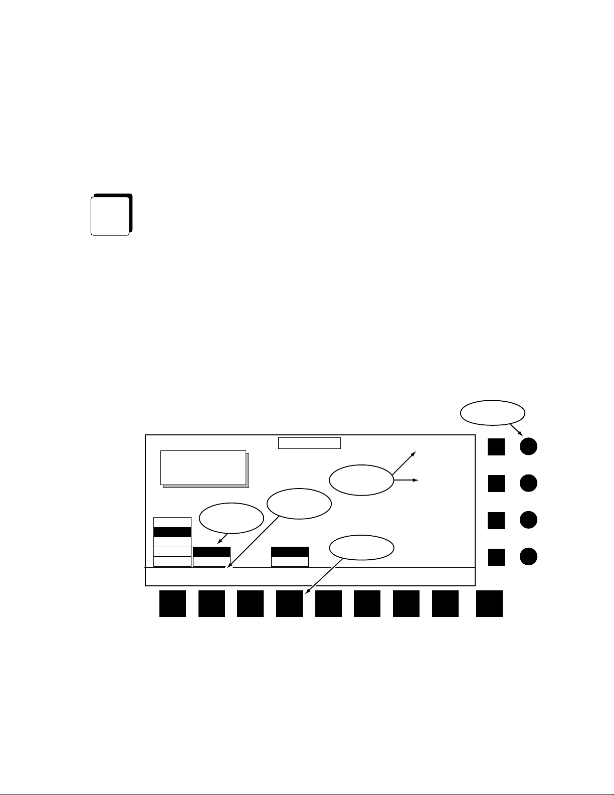
Video/Key/Mask
0600-01
Top
Menu
User
Assist
Clipboard
Effect
Operations
Edit
E-MEM
Mode
Override
Inputs
Control
(Ethernet)
Video/Key
Outputs
Control
External
Devices
Krystal Control Panel
Up to 8
Control Panels
Figure 1-1. Krystal Single Channel System
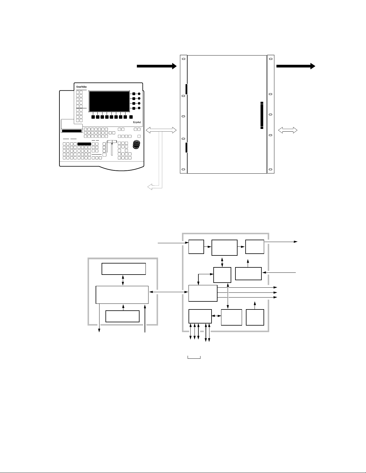
0600-12
Krystal Control Panel
FLAT PANEL DISPLAY
CONTROL PANEL CPU,
UPPER SWITCH,
LOWER SWITCH BOARDS
CONTROL PANEL
POWER SUPPLY
Diagnostic
Figure 1-2. Krystal Single Channel System Simplified Block Diagram
QWERTY
Keyboard
Video/
Key/Mask
Inputs
Ethernet
Video Processor Frame
Krystal Video Processor Frame
SERIAL
INPUT
SINGLE-CHAN
VIDEO
PROC I/O
EFFECT
MANAGER
I/O
Aux
Editor
Switcher
Serial
Ports
VIDEO
PROCESSOR
MODULES
VIDEO
PROC
CPU
MANAGER
GPI
Graphics in/Out
EFFECT
CPU
SERIAL
OUTPUT
REFERENCE
GENERATOR
FRAME
POWER
SUPPLY
Video/
Key/Depth
Outputs
Analog
Reference
Diagnostic
Router
Tally
1-4 Krystal 4300 Reference
Page 17
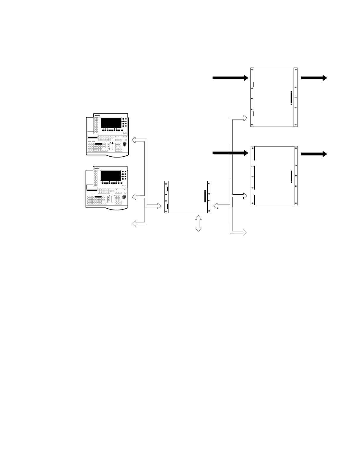
Top
Menu
User
Assist
Clipboard
Operations
Effect
Edit
E-MEM
Override
Mode
Top
Menu
User
Assist
Clipboard
Operations
Effect
Edit
E-MEM
Override
Mode
Small System
Controller Frame
Video/Key/Mask
Inputs
Ch A
Video/Key
Outputs
Video/Key/Mask
Inputs
Ch B
Video/Key
Outputs
Ch. A
Video Processor Frame
Ch. B
Video Processor Frame
Control (Proprietary)
Up to 4
Video Processor Frames
Up to 8 Krystal
Control Panels
With Up to 2
Concurrent Users
Control
(Ethernet)
0600-02
External
Devices
Control
Physical Description
Figure 1-3. Krystal Multi-Channel System, Small System Controller
Krystal 4300 Reference 1-5
Page 18
Section 1 — System Overview
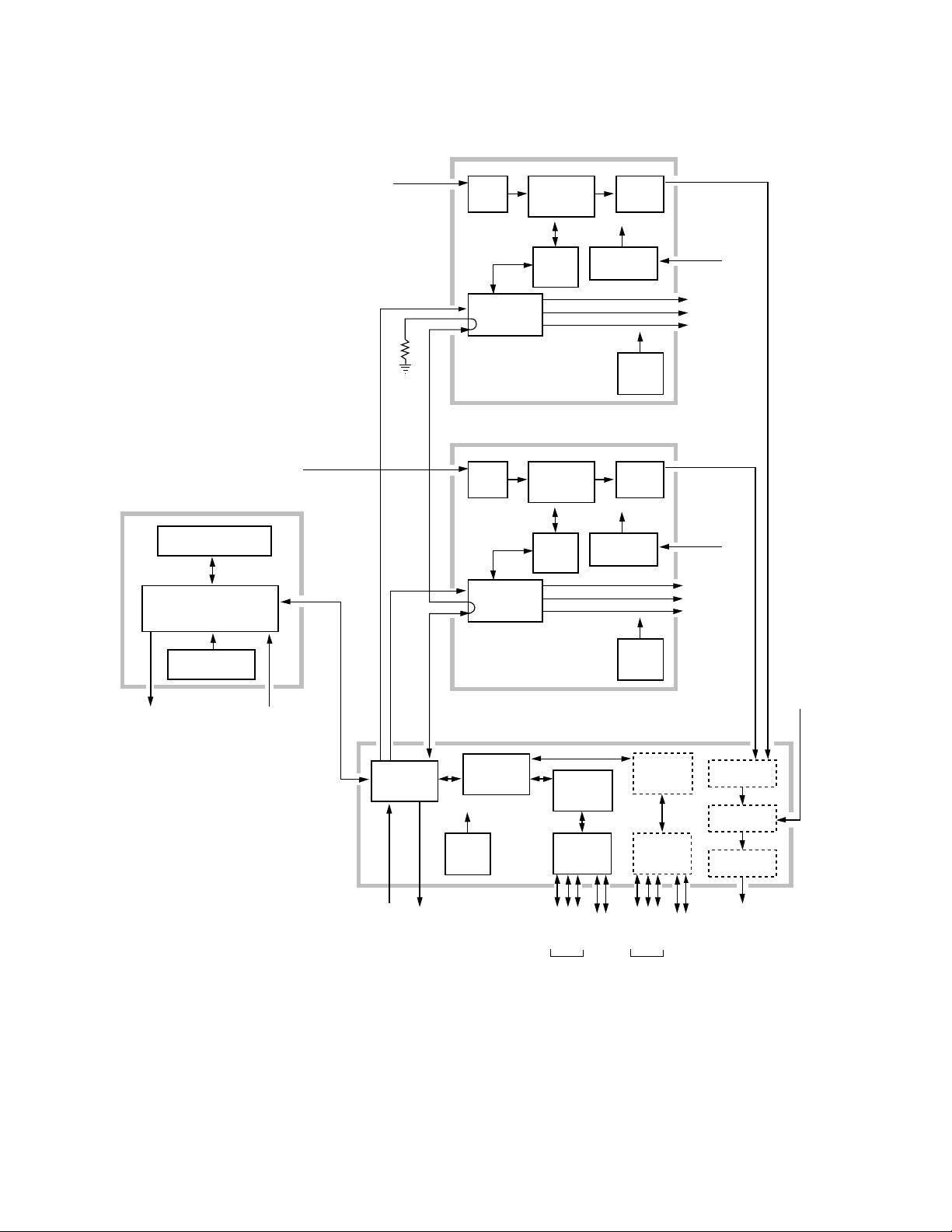
0600-13
Krystal Control Panel
FLAT PANEL DISPLAY
CONTROL PANEL CPU,
UPPER SWITCH,
LOWER SWITCH BOARDS
Video/
Key/Mask
Inputs
Video/
Key/Mask
Inputs
VP COMM
Terminator
Ch A Video Processor Frame
SERIAL
VP COMM
INPUT
MULTI-CHAN
VIDEO
PROC I/O
VIDEO
PROCESSOR
MODULES
VIDEO
PROC
CPU
Ch B Video Processor Frame
SERIAL
INPUT
MULTI-CHAN
VIDEO
PROC I/O
VIDEO
PROCESSOR
MODULES
VIDEO
PROC
CPU
SERIAL
OUTPUT
REFERENCE
GENERATOR
FRAME
POWER
SUPPLY
SERIAL
OUTPUT
REFERENCE
GENERATOR
Video/
Key/Depth
Outputs
Analog
Reference
Diagnostic
Router
Tally
Video/
Key/Depth
Outputs
Analog
Reference
Diagnostic
Router
Tally
Diagnostic
CONTROL PANEL
POWER SUPPLY
Ethernet
QWERTY
Keyboard
VP PARAM Ch A
RESOURCE
MANAGER
Analog
VP COMM
VP PARAM Ch B
I/O
FRAME
POWER
SUPPLY
Reference
Diagnostic
Small System Controller Frame
RESOURCE
MANAGER
CPU
EFFECT
MANAGER
CPU
EFFECT
MANAGER
I/O
Aux
Editor
Switcher
Serial
Ports
GPI
Figure 1-4. Krystal Dual Channel System Simplified Block Diagram
FRAME
POWER
SUPPLY
EFFECT
MANAGER
CPU
EFFECT
MANAGER
I/O
Aux
Editor
Switcher
Serial
Ports
Graphics in/Out
Video/
Key/Depth
Inputs
COMBINER
COMBINER
COMBINER
Key/Depth
GPI
Graphics in/Out
INPUT
2 x 2
OUTPUT
Video/
Outputs
Background
Video
Input
1-6 Krystal 4300 Reference
Page 19
0600-25
EFFECT
MANAGER
CPU
EFFECT
MANAGER
I/O
Switcher
Serial
Ports
Ethernet
Diagnostic
Large System Controller Frame
FRAME
POWER
SUPPLY
RESOURCE
MANAGER
I/O
RESOURCE
MANAGER
CPU
Editor
Aux
Graphics in/Out
GPI
COMBINER
INPUT
COMBINER
INPUT
TALLY
Up to 4
Video/Key/Depth
Inputs
Up to 4
Video/Key/Depth
Inputs
Analog
Reference
VP COMM
Loop thru to
all Channels
VP PARAM
to First 4 Channels
COMBINER
OUTPUT
Primary Video/Key Outputs
Secondary Video/Key Outputs
0600-36
VP PARAM
to Last 4 Channels
Tally Inputs
and Outputs
Preview Output
Background Input
EFFECT
MANAGER
CPU
EFFECT
MANAGER
I/O
Switcher
Serial
Ports
Editor
Aux
Graphics in/Out
GPI
COMBINER
OUTPUT
Primary Video/Key Outputs
Secondary Video/Key Outputs
Preview Output
Background Input
EFFECT
MANAGER
CPU
EFFECT
MANAGER
I/O
Switcher
Serial
Ports
Editor
Aux
Graphics in/Out
GPI
COMBINER
OUTPUT
Primary Video/Key Outputs
Secondary Video/Key Outputs
Preview Output
Background Input
EFFECT
MANAGER
CPU
EFFECT
MANAGER
I/O
Switcher
Serial
Ports
Editor
Aux
Graphics in/Out
GPI
COMBINER
OUTPUT
Primary Video/Key Outputs
Secondary Video/Key Outputs
Preview Output
Background Input
COMBINER
COMBINER
COMBINER
COMBINER
External
Devices
Control
Large System
Controller Frame
Video/Key/Mask
Inputs
Physical Description
Video/Key
Outputs
Up to 8 Krystal
Control Panels
Control (Ethernet)
with up to 4
Concurrent Users
Figure 1-5. Krystal Multi-Channel System, Large System Controller
Control (Proprietary)
Up to 8
Video Processor Frames
Figure 1-6. Large System Controller Simplified Block Diagram
Krystal 4300 Reference 1-7
Page 20
Section 1 — System Overview
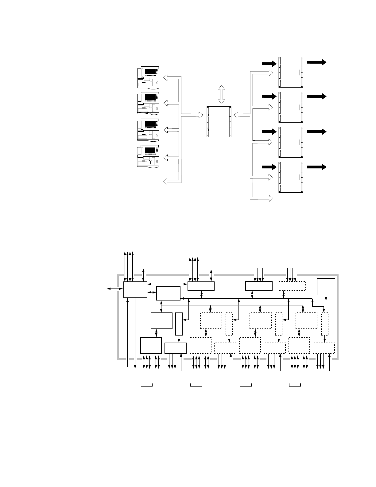
System Control
In all Krystal systems, each operator uses a Control Panel to acquire an
Effect Manager. The Effect Manager, in turn, acquires the Video Processor
channel(s) it will use to create and run digital video effects. When the operator acquires an Effect Manager in a single channel system, it automatically
acquires the single channel, if available. In a multi-channel system, each
operator acquires a different Effect Manager, and each operator selects
which of the available Video Processor channels to use. A Resource
Manager module is included in multi-channel systems to handle internal
system communications between the Krystal components.
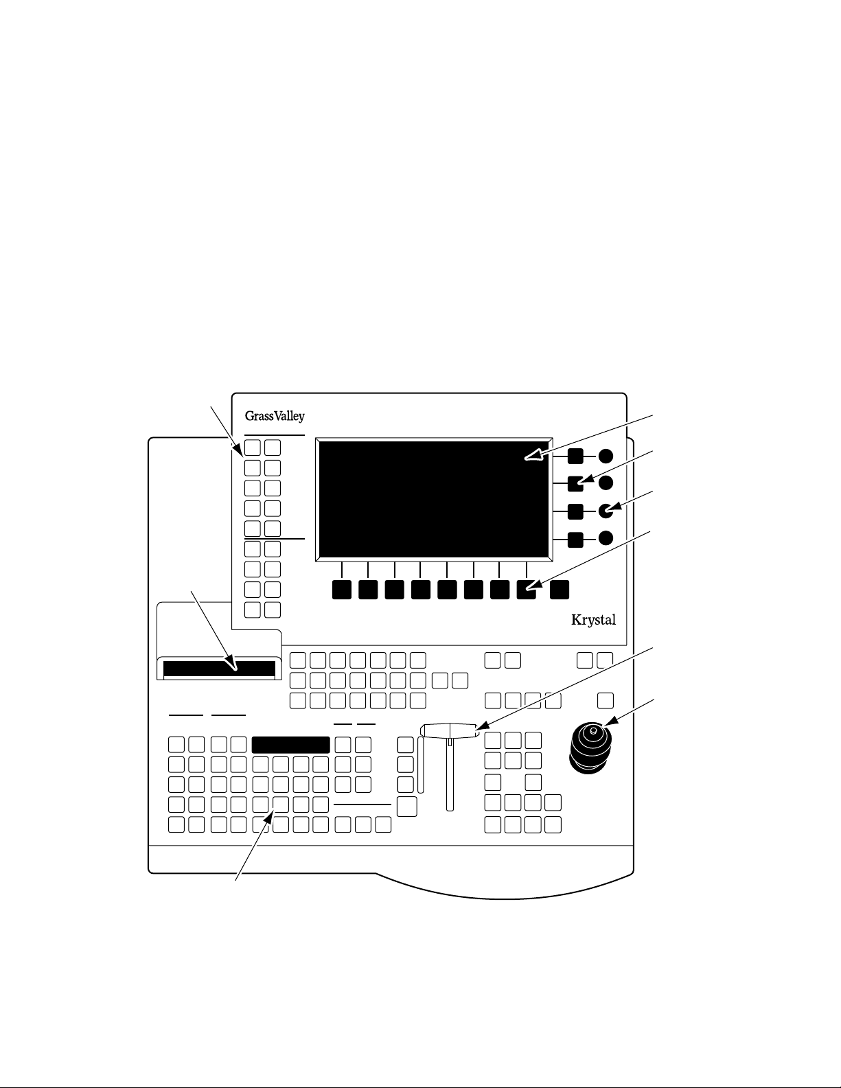
Control Panel
Top Menu
Buttons
Floppy Disk
Drive
Clipboard
Operations
Clear
Restore
Work
Work
Buffer
Buffer
Cut
Delete
Copy
Paste
Clear
Marks
Mark
Mark
Block
Effect
Edit
Prev.
Go To
KF
KF
Dur.
Start
Time
Modify Insert
Next
Go To
Time
Effect
Dur.
Insert
Before
After
System
Setup
User
Tools
File
Oper.
Macro View
Control
Timeline
Last
Menu
Picture
Top
Menu
Picture
Frame
Key/
Stencil
Input/Run
Output
Path
User
Assist
Graphic
Display
Help
Macro
123456
Deleg.
Clear
9
Entry
21
0 +/-
Detent
Trim
3
Enter
47586
.
E-MEM
Mode
Recall
Const.
Dur.
Effect
Auto
Put
Run
Get Partial
KF
Override
FreezeFreeze
12
Menu Display
Transfer Buttons
Soft Knobs
Soft Buttons
Exit
MacroMacroMacroMacroMacroMacro
Shift
EnableEnableEnableEnableEnable EnableEnable
G1 G2 Cam4321
Deleg.Deleg.Deleg.Deleg.Deleg.Deleg.
CamG2G14321
Stop
Next
Reverse
Rewind
Run
Hold
Input
Loop
Time
Mark
Cursor
Cursor
TargetSource
Locate
Size/
Rotate
3D
Locate
Locate
Spin
Axis
Menu
Control
Persp.
Skew Post
Aspect
XYZ
Near
Far
Knob
Control
Xform
Center
Lever Arm
Joystick
Numeric Keypad and LED Display
0440_00_01
Figure 1-7. Krystal Control Panel
1-8 Krystal 4300 Reference
Page 21
Physical Description
The Krystal Control Panel is easy to learn and provides a comprehensive
artistic tool kit for effects generation. Each panel includes a floppy disk
drive for loading and storing effects, system configuration files, and user
preferences.
Krystal Control Panels communicate with the Video Processor frame
(single channel system) or the System Controller frame (multi-channel
system) via a dedicated Local Area Network (LAN). The LAN cable may be
a customer supplied 50Ω coax, or an optional LAN Cable Kit may be
ordered from Tektronix/Grass Valley Products. Up to eight Control Panels
may be connected to the network.
The Krystal Control Panel is divided into upper and lower panel areas
(Figure 1-7). The upper panel contains the flat panel menu display and
various knobs and buttons for making menu selections and adjusting video
parameters. The lower panel contains the controls for picture transformation, effect editing and running, and has a keypad, joystick, and lever arm.
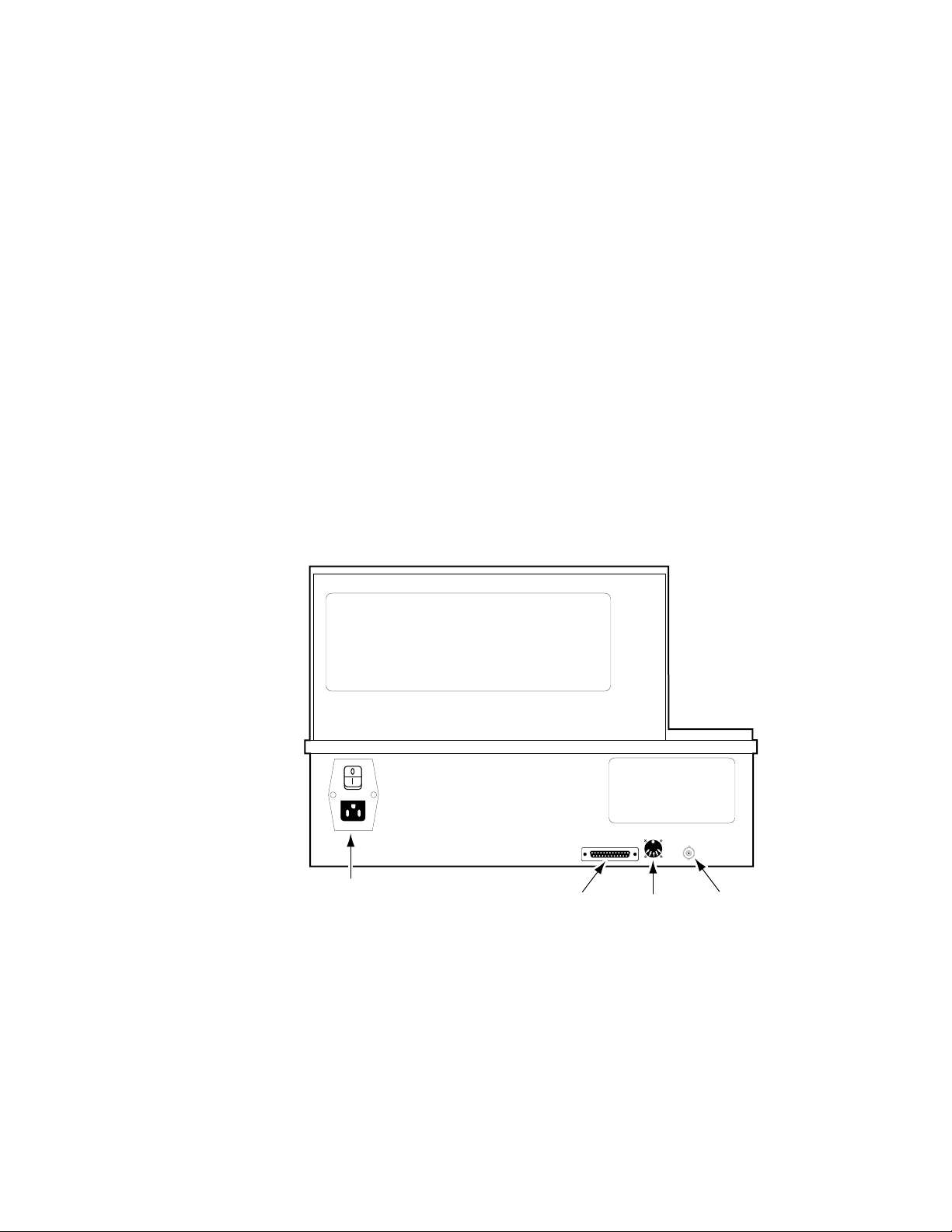
A diagnostic port, a connector for an optional QWERTY keyboard, the CP
COMM Ethernet connector, and the AC power connector are located on the
rear of the panel (Figure 1-8).
0600-08
KEYBOARD
J3
Keyboard
J2
CP COMM
J1
CP COMM
(Ethernet)
AC Power Switch
and Line Cord
TERMINAL
Diagnostic
Terminal
Figure 1-8. Krystal Control Panel, Rear View
Krystal 4300 Reference 1-9
Page 22

Section 1 — System Overview
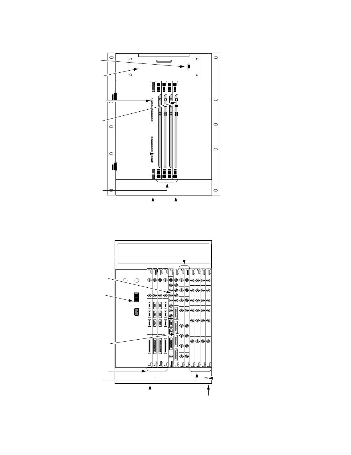
Video Processor Frame
The Krystal Video Processor frame contains modules that receive the
incoming video and key signals, performs the actual video manipulations,
and outputs the processed video. On single channel Krystal systems the
Video Processor frame also holds the Effect Manager modules that communicate with the Control Panel and direct the video processing activity. On
multi-channel systems some of these communications and control modules
are located in the System Controller frame.
The Video Processor frame is a 13 rack unit frame that mounts in a standard
19-inch equipment rack. The frame holds large modules installed from the
front (Figure 1-9), and smaller I/O modules installed from the back
(Figure 1-10). Some of the front loaded modules are options, and some
modules may have standard or optional mezzanines (daughter boards).
1-10 Krystal 4300 Reference
Page 23
Physical Description
EFFECTS
MANAGER
I/O
Reset
Sw
Reset
Diag
POWER
DC
+12
+5
–12
Over
Temp
Reset
Diag
TX1
RX1
TX2
RX2
TX3
RX3
FRX
Vid
Reset
Reset
Sw
Vid
Proc
ID
3
4
0600-04
Cooling
Fan
Frame Modules
(Slots 1-17)
DC Power
Switch
Front Door
Removed
Slot 1 Slot 5 Slot 10 Slot 17
Video Processor
CPU Reset Button
Effect Manager
CPU Reset Button
Hardware ID
Slot ... Module
1 ........ Source Effects
2 ........ Input Recursive
3,4 ..... vacant
5 ........ Defocus
6 ........ Filter
- Filter Memory
- Motion Detector
7 ........ Filter Control
8,9 ..... vacant
10 ...... Interpolator (Y-C)
- Memory (2, older systems)
11 ...... Interpolator (Key/Drop Shadow)
- Memory (older systems)
- Memory Option (older systems)
12 ...... Post Transform
- Light Source Option
13 ...... Reverse Address Generator (RAG)
- Kurl (2D Warp) Option
14 ...... vacant
15 ...... Output Recursive
16 ...... Video Processor CPU
17 ...... Effect Manager CPU*
- Graphics
* In multi-channel systems the Effect
Manager CPU (slot 17) is located in the
System Controller frame.
INCLUDING INTERFERENCE THAT MAY CAUSE UNDESIRED OPERATIONS.
THIS DEVICE COMPLIES WITH PART 15 OF THE FCC RULES.
OPERATION IS SUBJECT TO THE FOLLOWING TWO CONDITIONS:
(1) THIS DEVICE MAY NOT CAUSE HARMFUL INTERFERENCE
(2) THIS DEVICE MUST ACCEPT ANY INTERFERENCE RECEIVED
PROFESSIONAL USE
VIDEO EQUIPMENT
LISTED
TUV Rheinland
geprufte
Sicherheit
5J50
RATED VOLTAGE RANGE:90-264 VAC
FREQUENCY: 47-63 Hz
RATED CURRENT: 15 amps
PROGRAM
PREVIEW
KEY/
DEPTH
CONTROL
PANELS
J3
J2
SERIAL
OUTPUT
J1
INPUT A
INPUT B/
MASK
INPUT A
INPUT B
J3
J2
SERIAL
INPUT
J1
J4
KEY
INPUTS
VIDEO
INPUTS
ROUTER
DIAG
J3
J2
J1
VIDEO
PROCESSOR
J4
TALLY
SERIAL
PORTS
GPI
J5
J4
INPUT
J3
OUTPUT
J2
J1
GRAPHICS
EFFECTS
MANAGER
J6
ANALOG
REFERENCE
INPUT
J2
REFERENCE
GENERATOR
J1
l
0
Cooling Exaust
(intakes at bottom
of both sides)
Power Supply
(inside)
I/O Modules
Earth Ground
Lug
AC Power
Switch/Breaker
and AC Line Cord
Slot 17 Slot 15 Slot 3 Slot 1
0600-05
Slot ...Module
1.........Serial Inputs
2.........vacant
3.........Reference Generator
4-14 ...N/A
15.......Serial Outputs
16.......Video Processor I/O*
17.......Effect Manager I/O*
* In multi-channel systems the Effect
Manager I/O is located in the System
Controller Frame and a diff erent Pooled
Video Processor I/O Module is used.
Figure 1-9. Video Processor Frame, Front View
Figure 1-10. Video Processor Frame, Rear View
Krystal 4300 Reference 1-11
Page 24

Section 1 — System Overview
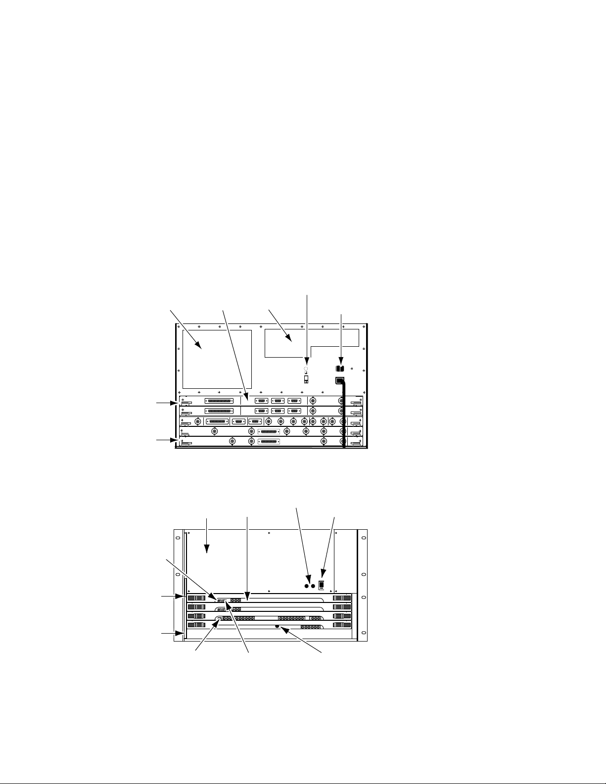
System Controller Frame
Large System Controller
The Krystal Large System Controller frame is available for larger multichannel Krystal systems of up to eight channels and up to four users. The
Large System Controller frame contains control modules used to manage
the resources in the pool, and can contain optional combiner modules used
to join four channels of processed video into combined video/key output
streams.
On Large System Controllers with combining capabilities, any Krystal
Channel can be used by any single user at any time. These sources can be
combined by any user in a variety of ways. Complete input source routing
is incorporated into the unit. On these systems each Combiner Output
module is dedicated to a specific Effect Manager.
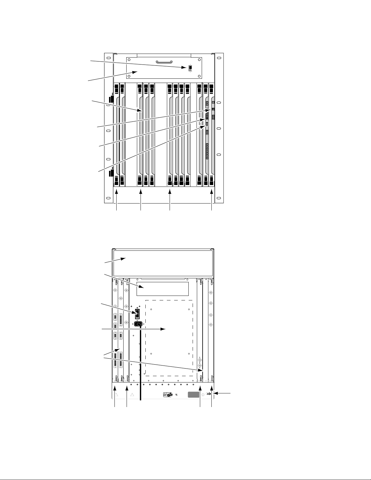
The Large System Controller frame is a 13 rack unit frame that mounts in a
standard 19-inch equipment rack (Figure 1-11 and Figure 1-12).
1-12 Krystal 4300 Reference
Page 25
Physical Description
EFFECTS
MANAGER
I/O
Reset
Sw
Reset
Diag
EFFECTS
MANAGER
I/O
Reset
Sw
Reset
Diag
EFFECTS
MANAGER
I/O
Reset
Sw
Reset
Diag
EFFECTS
MANAGER
I/O
Reset
Sw
Reset
Diag
POWER
DC
0600-37
Cooling
Fan
DC Power
Switch
Front Door
Removed
Effect
Managers
(up to 4)
Resource
Manager
Reset
Button
Effect
Manager
Reset
Button
Slot 8 Slot 12
RESOURCE
MANAGER
I/O
RESET
SW
RST
TMP
LED1
LED2
TX1
RX1
TX2
RX2
TX3
RX3
COL
RCV
JAB
PRT
ERR
VP
PARAM
50HZ
60HZ
+5
+12
-12
Slot ...Module
1-7 .....vacant
8.........4 Ch. Combiner Resource Mgr
9-12 ...Effect Manager CPU(s)
13-17 .vacant
Figure 1-11. Large System Controller Frame, Front View
Combiner Input
0600-38
(up to 2)
Resource
Manager I/O
AC Power
Switch and
L:ine Cord
Combiner Tally
Effect Manager
I/Os (up to 4)
Output (up to 4)
Combiner
EFFECTS
MANAGER
GRAPHICS
INPUT
J1
OUTPUT
0
AC
POWER
J2
l
SERIAL
PORTS
EDITOR
J3
SWITCHER
J4
AUX
J5
GPI
J6
RESOURCE
EFFECTS
EFFECTS
EFFECTS
VP PRAM
PREVIEW
PREVIEW
PREVIEW
SECONDARY
SECONDARY
BACKGROUND
PREVIEW
VIDEO
VIDEO
VIDEO
VIDEO
OUTPUT
OUTPUT
OUTPUT
OUTPUT
J1
J1
J1
PROGRAM
OUTPUT
PROGRAM
KEY/DEPTH
OUTPUT
OUTPUT
KEY/DEPTH
OUTPUT
COMBINER
OUTPUT
J1
PROGRAM
PROGRAM
PROGRAM
VIDEO
VIDEO
VIDEO
VIDEO
OUTPUT
OUTPUT
OUTPUT
J2
J2
J2
J2
PROGRAM
PROGRAM
PROGRAM
KEY/DEPTH
KEY/DEPTH
KEY/DEPTH
OUTPUT
OUTPUT
OUTPUT
J3
J3
J3
J3
SECONDARY
SECONDARY
SECONDARY
VIDEO
VIDEO
VIDEO
VIDEO
OUTPUT
OUTPUT
OUTPUT
J4
J4
J4
J4
SECONDARY
SECONDARY
SECONDARY
KEY/DEPTH
KEY/DEPTH
KEY/DEPTH
OUTPUT
OUTPUT
OUTPUT
J4
J4
J4
J4
BACKGROUND
BACKGROUND
BACKGROUND
VIDEO
VIDEO
VIDEO
VIDEO
INPUT
INPUT
INPUT
INPUT
J6
J6
J6
J6
COMBINER
COMBINER
COMBINER
OUTPUT
OUTPUT
OUTPUT
MANAGER
MANAGER
MANAGER
MANAGER
GRAPHICS
GRAPHICS
GRAPHICS
INPUT
INPUT
INPUT
J1
J1
OUTPUT
OUTPUT
OUTPUT
J2
J2
SERIAL
SERIAL
SERIAL
PORTS
PORTS
PORTS
EDITOR
EDITOR
EDITOR
J3
J3
SWITCHER
SWITCHER
SWITCHER
J4
J4
AUX
AUX
AUX
J5
J5
GPI
GPI
J6
J6
VIDEO
50HZ
ANALOG REF IN
60HZ
ANALOG REF IN
1
1
1
1
TALLY DRVR
VP PARAMETERSROUTERDIAGNOSTICS
TALLY DRVR
TALLY RCVR
TALLY RCVR
VIDEO
INPUT 1
INPUT 1
J11
J1
J1
J2
VIDEO
VIDEO
INPUT 2
INPUT 2
J3
J2
J2
J4
VIDEO
VIDEO
INPUT 3
INPUT 3
J5
J3
J3
VIDEO
VIDEO
INPUT 4
INPUT 4
J4
J4
KEY/DEPTH
KEY/DEPTH
INPUT 1
INPUT 1
J5
J5
KEY/DEPTH
KEY/DEPTH
INPUT 2
INPUT 2
J6
J6
KEY/DEPTH
KEY/DEPTH
INPUT 3
INPUT 3
J7
J7
KEY/DEPTH
KEY/DEPTH
INPUT 4
INPUT 4
J8
J8
COMBINER
COMBINER
INPUTS
INPUTS
J1
J1
J2
J3
J4
J2
J5
J6
J7
J3
J8
J4
J9
J5
J10
VP COMM
GPI
J11
J12
J6
CP COMM
Earth Ground
Slot ... Module
1-4..... 4 Ch. Combiner Output(s)
- 4 Ch. Combiner Mezzanine
5-6..... 4 Ch. Combiner Input(s)
7 ........ 4 Ch. Combiner Tally
8-12... Effect Manager I/O(s)
Lug
Slot 12 Slot 1
Figure 1-12. Large System Controller Frame, Rear View
Krystal 4300 Reference 1-13
Page 26
Section 1 — System Overview
Small System Controller
Older Krystal systems may have been configured with a Small System Controller frame.
The Krystal Small System Controller frame is for multi-channel Krystal
systems of up to four channels. The Small System Controller frame contains
control modules used to manage the resources in the pool, and can contain
optional combiner modules used to join two channels of processed video
into a single video/key output stream.
The Small System Controller is a seven rack unit frame intended to be
mounted in a standard 19 inch equipment rack. The frame holds large
modules installed horizontally from the front (Figure 1-14), and smaller I/
O modules installed horizontally from the back (Figure 1-13).
Cooling
Exhaust
Controller
I/O Modules
Cooling
Intake
Earth Ground
Lug
AC Power Switch
and Line Cord
Slot 1
Slot 5
Front Door
Removed
RAM
Battery
Switch
Slot 1
Slot 5
POWER
I
0
GRAPHICS GRAPHICS
MANAGER
OUTPUT
SERIAL
TALLY RECEIVER
PORTS
J3
J2
EDITOREDITOR
SWITCHERSWITCHER
J7
VP PARAMETERSROUTERDIAGNOSTICS
J4
OUTPUT
PORTS
SERIAL
J3
J2
J4
J5
J6
60HZ
ANALOG REF IN
J3
DEPTH
VIDEO
KEY/
B
GPI
J5
J6
J6
J11
J12
CP COMM
GPI
VP COMM
J7
B BKGND
J5
DEPTH
KEY/
J4
AUXAUX
J5
J4
J10
J8
J9
J6
J5
A BKGND
TALLY DRIVER
J4
J3
VIDEO
B
EFFECTS
INPUT
J1
MANAGER
EFFECTS
INPUT
J1
J3
J1
RESOURCE
J2
MANAGER
50HZ
ANALOG REF IN
J1
J2
COMBINER
INPUTS
DEPTH
VIDEO
KEY/
A
J1
J2
COMBINER
OUTPUTS
DEPTH
VIDEO
KEY/
A
Figure 1-13. Small System Controller Frame, Rear View
Power
Supply
I/O
EFFECTS
MANAGER
I/O
EFFECTS
MANAGER
I/O
MANAGER
RESOURCE
2 X 2
COMBINER
SW
SW
BATT
RESET
SW
SW
BATT
RESET
SW
RESET
RST
TMP
LED1
Modules
DS 1
DS 2
DS 3
DS 1
DS 2
DS 3
LED2
TX1
RX1
TX2
RX2
TX3
RX3
FusesController
DC Power
Switch
DC
POWER
VP
PARAM
+5
+12
COL
RCV
JAB
-12
PRT
ERR
50HZ
60HZ
RST
RS485TXCH 1
TAXI
RS485RXCH2
TAXI
DIAG
Slot ... Module
1........ Effect Manager 1 I/O
2........ Effect Manager 2 I/O Option
3........ Resource Manager I/O
4........ 2 x 2 Combiner Inputs Option
5........ 2 x 2 Combiner Outputs Option
0600-07
Slot ... Module
1........ Effect Manager 1 CPU
- Graphics Option
2........ Effect Manager 2 CPU Option
- Graphics Option
3........ Resource Manager CPU
4........ 2 x 2 Combiner CPU Option
5........ vacant
0600-06
Resource Manager
Reset Button
Effect Manager CPU
Reset Buttons
Combiner CPU
Reset Button
Figure 1-14. Small System Controller Frame, Front View
1-14 Krystal 4300 Reference
Page 27

Module Descriptions
Physical Description
CAUTION
■
■
■
■
Modules in Krystal systems cannot be hot-swapped safely. Always power down
Krystal frames before removing or inserting Krystal modules.
Serial Input and Output I/O modules — Serial Input modules convert
incoming serial digital component video signals to parallel format for
internal processing by the Video Processor frame. The Serial Output
modules convert parallel video back to serial digital format.
Effect Manager CPU and I/O modules — The Effect Manager module
calculates the parameters required, and stores these effects parameters.
It passes these parameters to the Video Processor CPU which uses them
to control the video processing electronics. Multi-channel systems use
a different type of Effect Manager, and in these systems the Effect Managers are located in the System Controller frame.
Video Processor CPU and I/O modules — Each Video Processor CPU
module controls the operation of the modules and options installed in
a single Video Processor frame. It receives the parameters to produce an
effect from the Effect Manager and passes them to the video modules in
that frame. Two different Video Processor I/O modules are available,
one for single channel Krystal systems and one for pooled Krystal systems.
Reverse Address Generator (RAG) module — This module continually
calculates the source pixel address for each output pixel in the transformed video.
■ Post Transform module — Using addresses from the RAG module, this
module generates offset addresses for key and video drop shadows. It
also generates perspective fade, blur, and dim effects.
■ Interpolator modules — Using addresses generated by the RAG and
Post Transform modules, these modules look at the source video and
determine the pixel values to be used in the transformed video output.
■ Filter Control module — This module uses transform information to set
up filter control factors (for each input pixel) to control the Filter
module.
■ Filter module — This module provides anti-aliasing filtering for effects.
It also provides motion detect functions, an embossed video function,
and a key processor for mixing video with defocused video and/or
mattes.
■ Source Effects module — This module provides a number of functions,
including external mask processing, mask pattern generation, self and
external key processing, rectangular and pattern crops, coring, video
bitmap, hue rotation, and picture border generation.
■ Reference Generator module — This module generates internal syncs
and clocks from the facility reference (color black).
Krystal 4300 Reference 1-15
Page 28

Section 1 — System Overview
■ Resource Manager CPU and I/O modules — The Resource Manager
■ Input Recursive module — This module allows the processing of
■ Output Recursive module — This module allows the processing of
■ Defocus module — This module permits altering the sharpness of
CPU module is the center of systems communication between the
Control Panel, Video Processors, and System Controller frame in multichannel systems. Two different types of Resource Manager CPUs exist,
one used for the Small System Controller and one for the Large System
Controller. The Resource Manager
I/O module interfaces between the Resource Manager CPU module
and the rest of the Krystal system.
incoming video for freeze, mosaic, and motion decay effects that appear
within the incoming video raster.
output (post transform) video for freeze, motion decay, montage, and
trail effects that can appear outside and inside the raster of the
incoming video.
video and key signals, for defocus and glow effects.
■ 2 x 2 Combiner module — This module provides mixing and keying cir-
cuitry for combining two foreground video and key inputs and a background matte or video input in various ways.
■ 2 x 2 Combiner Input and Output modules — The 2 x 2 Combiner Input
module convert incoming serial digital component video signals to parallel format and routes them to the Combiner for processing. The 2 x 2
Combiner Output module receives the processed signals from the
Combiner, converts the parallel video back to serial digital format, and
routes the video to its output connectors.
■ Four Channel Combiner Input and Output modules — The Four
Channel Combiner groups four sets of serial digital inputs on each
input module. Each Effect Manager has a single dedicated Four
Channel Combiner Output module, which produces a set of serial
digital combined output signals. Each Output module also has a background video input.
■ Four Channel Combiner Tally — This module has tally input and
output connectors and system control ports for Krystal Channels 5-8.
Additional options are available that consist of mezzanine boards that are
installed onto some of the Krystal modules.
1-16 Krystal 4300 Reference
Page 29

Module and Mezzanine Part Numbers
Table 1-2. Krystal Module and Mezzanine Part Numbers
Module Name P/N Location, Mezzanines (M), Notes
Source Effects 066211-00 (VP front) Located in Video Processor front bay
Input Recursive 066212-00 (VP front)
Defocus
Filter
Filter Control 066217-00 (VP front)
Y/C K/DS Interpolator
(Newer Systems)
Y/C Interpolator
(Older Systems)
K/DS Interpolator
(Older Systems)
Post Transform
Reverse Address Generator
(RAG)
Output Recursive 066258-00 (VP front)
Video Processor CPU 066223-00 (VP front)
Effect Manager CPU
Serial Inputs 066229-00 (VP back)
Serial Outputs (Older Systems) 066227-00 (VP back) Single Output Connectors
Serial Outputs (Newer Systems) 066227-01 (VP back) Dual Output Connectors
Video Processor I/O (single) 066226-00 (VP back) Single Channel systems only
Video Processor I/O (pooled) 066237-00 (SC back) Multi-Channel systems only
Effect Manager I/O 066225-00
Resource Manager I/O 066231-00 (SC back) Large and Small System Controllers
4 Ch. Comb. Resource Manager 066295-00 (SC front) Large System Controller only
4 Ch. Comb. Input 066293-00 (SC back) Large System Controller only
4 Ch. Comb. Output
4 Ch. Comb. Tally 066298-00 (SC back) Large System Controller only
Resource Manager 066230-00 (SC front) Small System Controller only
2 x 2 Combiner CPU 066240-00 (SC front) Small System Controller only
2 x 2 Combiner Input 066204-00 (SC rear) Small System Controller only
2 x 2 Combiner Output 066205-00 (SC rear) Small System Controller only
066216-00
- 066242-00
066215-00
- 066242-00
- 066243-00
966250-50 (VP front)
066213-00
- 066235-00
066261-00
- 066235-00
066222-01
- 066236-00
066220-01
- 066221-10
066224-00
- 066239-00
066294-00
- 066297-00
Physical Description
(VP front)
(M) Filter Memory (required)
(VP front)
(M) Filter Memory (required)
(M) Motion Detector (required)
(VP front)
(M) Interpolator Memory (2) (required)
(VP front)
(M) Interpolator Memory (2) (1 required, 1 optional)
(VP front)
(M) Light Source (optional)
(VP front)
(M) Kurl (2-D Warp) - Splash PLD 152169-00 (optional)
(VP front) Single Channel Systems
(SC front) Multi-Channel Systems
(M) Graphics (optional)
(VP back) Single Channel Systems
(SC back) Multi-Channel Systems
(SC back) Large System Controller only
(M) 4 Ch. Combiner (required)
Krystal 4300 Reference 1-17
Page 30
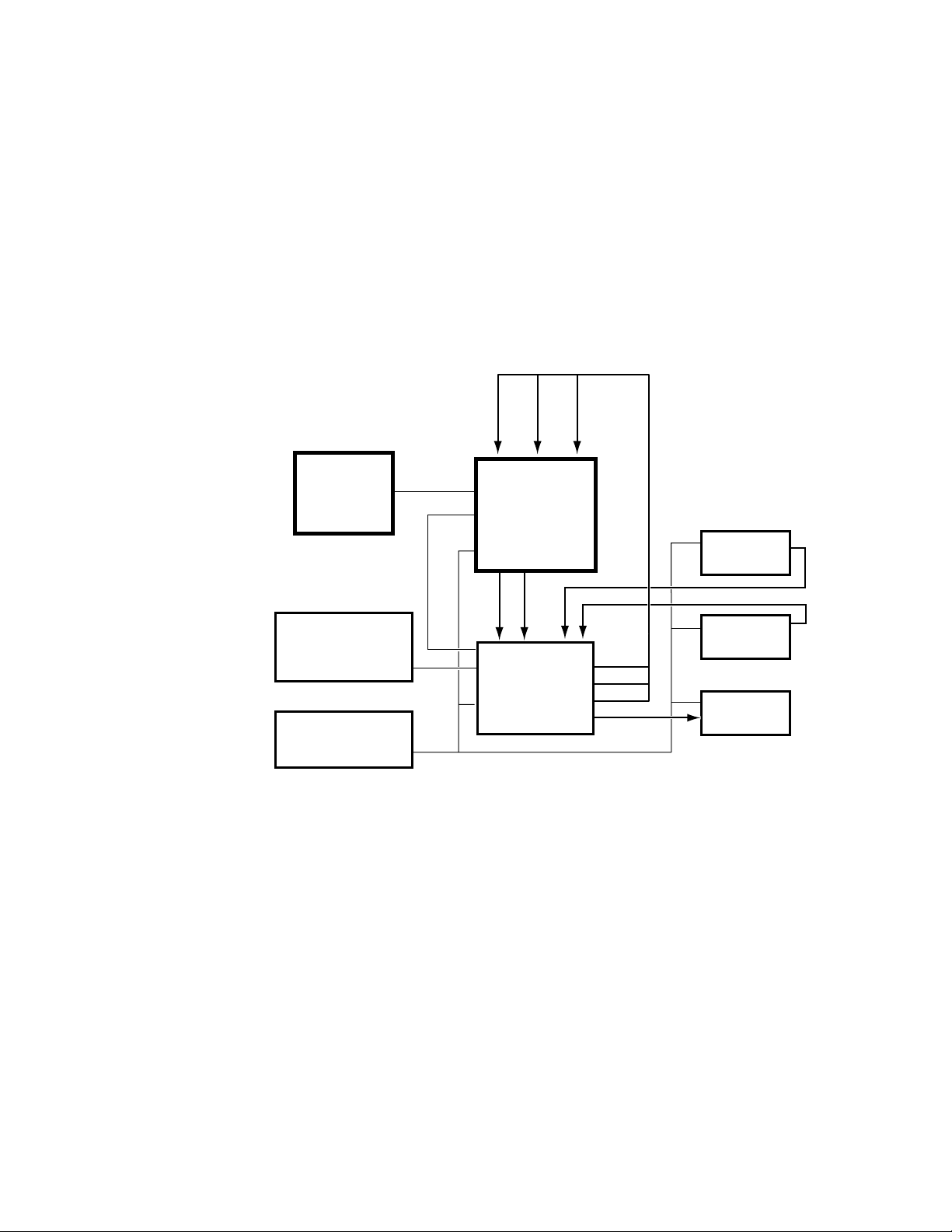
Section 1 — System Overview
Facility Examples
Examples of some typical facilities are included here to give you a sense of
the variety of configurations possible. More detailed information about
system installation and configuration is presented later in this manual.
Single Channel Krystal Facility
Figure 1-15 and Figure 1-16 depict how a single channel Krystal system
may be incorporated into a post-production editing suite.
A Video
0600-23
A Key
Mask (B Key)
Krystal
Control Panel
Production Switcher
Control Panel
Edit Controller
Figure 1-15. Single Channel Krystal Edit Facility, External Routing
Krystal Control
Interface
Switcher / Krystal
Edit Control
Krystal Video
Processor Frame
Key
Video
Production
Switcher Frame
Video
Key
Mask
Aux Out
Play VTR
Play VTR
Record VTR
1-18 Krystal 4300 Reference
Page 31
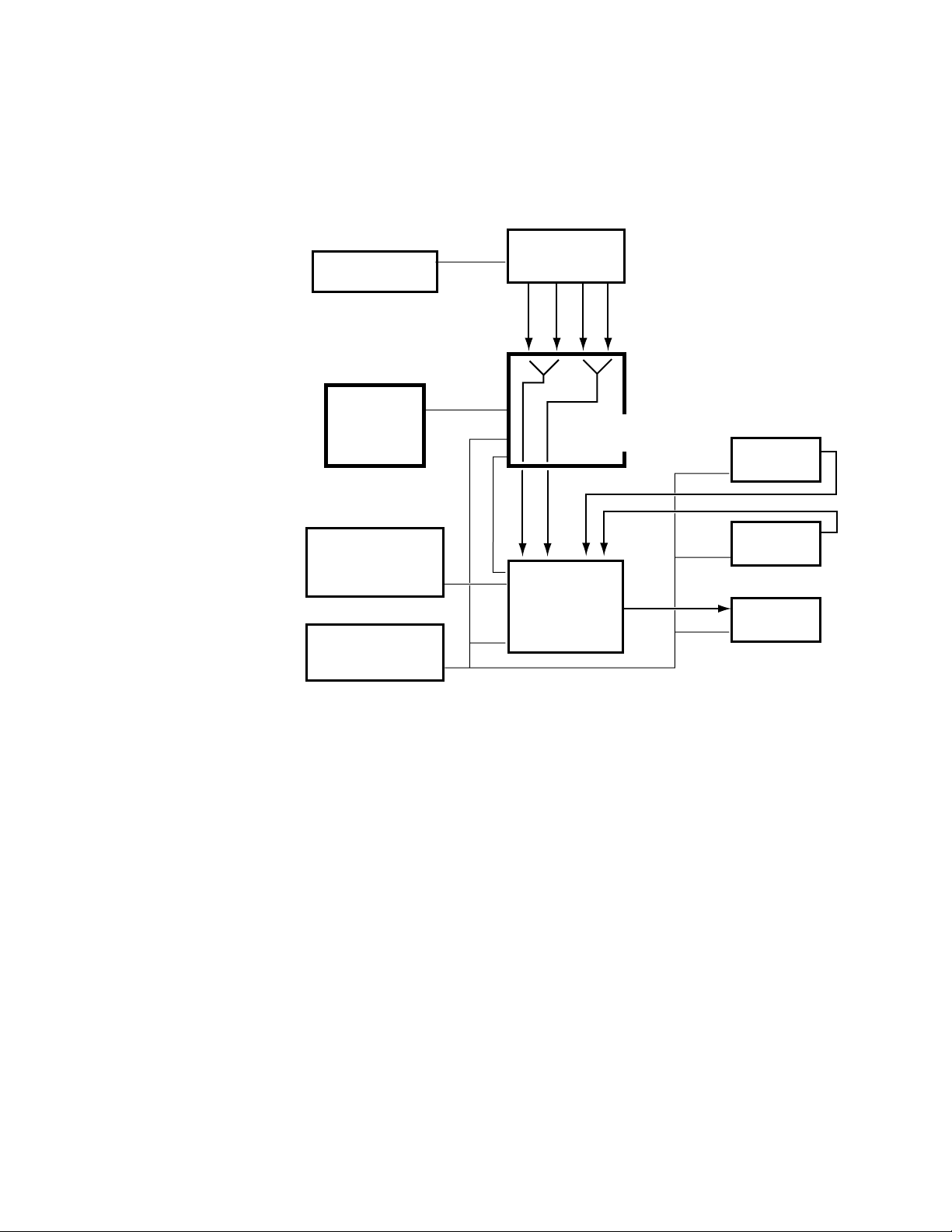
Physical Description
Krystal
Control Panel
A Video
Video
Key
A Key
B Video
B Key
0600-10
Edit Controller
Record VTR
Play VTR
Routing Switcher
Control Panel
Routing
Switcher
Edit Control
Edit Control
Play VTR
Krystal Video
Processor Frame
Production
Switcher Frame
Production Switcher
Control Panel
Switcher / Krystal
Interface
Figure 1-15 illustrates a system in which the Krystal system is configured
to control the Switcher as a source selector. The Krystal DPM is configured
for separate Video, Key, and external Mask inputs. Both the Switcher and
Krystal systems are also under editing system control.
Figure 1-16. Single Channel Krystal Edit Facility, Internal Switching
Figure 1-16 illustrates internal source switching, with the A and B Krystal
inputs fed via an external routing switcher. The routing switcher is controlled manually. The Krystal system in this example does not control the
routing or production switchers. One set of router outputs feeds the Krystal
A channel inputs, and the other the B inputs. This Krystal system can automatically switch between the currently selected router inputs when the
manipulated image rotates edge on within an effect. Both the Switcher and
Krystal systems are also under editing system control.
Krystal 4300 Reference 1-19
Page 32

Section 1 — System Overview
Two Channel, Two User Krystal Facility
In Figure 1-17 two Krystal Video Processor channels and two Krystal
Control Panels are incorporated into a facility that has separate editing and
control rooms. The Krystal system is configured to use the auxiliary busses
on the switchers as input source selectors. This lets the Krystal system to
command the switcher to select different Aux bus crosspoints during an
effect.
0600-11
Control Room
Production Switcher
Control Panel
Krystal
Control Panel
Suite 1
Control Room
Krystal
Control Panel
Edit Suite
Production Switcher
Control Panel
Edit Controller
Input
Crosspoints
Video
Control Room
Production
Switcher Frame
Krystal Control (Ethernet)
Krystal Control (Serial)
Input
Crosspoints
Video
Edit Suite
Production
Switcher Frame
Key
Aux A Video
Aux A Key
Aux B Video
Aux B Key
Key
Aux A Video
Aux A Key
Aux B Video
Aux B Key
Program
Video
Program
Video
Key A
Video A
Krystal Video
Processor Frame
Ch. A
Key
Video
To Combiner
Small System
Controller Frame
Resource Mgr
Effect Mgr 1
Effect Mgr 2
2x2 Combiner
Combiner
Out B
Video A
Combiner
Key A
Krystal Video
Processor Frame
Ch. B
Key B
Video B
Out A
Key B
Video B
Suite 2
Editing Room
Edit Control
VTRs
Video
Key
Figure 1-17. Two User Dual-Channel Krystal Facility Example
This installation allows a user in either location to acquire one or both
Krystal channels. The Krystal channels in both rooms are configured for A/
B Input routing. When suite 1 is controlling both Krystal channels, the A
video and key inputs on those channels are automatically selected for use.
1-20 Krystal 4300 Reference
Page 33

Physical Description
When suite 2 is controlling the channels the B video and key inputs on
those channels are selected. The operator in each suite must acquire the
correct Effect Manager to control that suite’s Switcher Aux bus selections.
This facility is also equipped with a 2 x 2 Combiner that allows the user to
combine both Krystal channels, and have the combined video and key
return to crosspoints on the switchers.
Krystal 4300 Reference 1-21
Page 34

Section 1 — System Overview
Eight Channel Four User Krystal Facility
In Figure 1-18 eight Krystal Video Processor channels and four Krystal
Control Panels are incorporated into a large facility.
Router
Control Panel
Switcher
Control Panel
Krystal
Control Panel
Suite 1
Router
Control Panel
Switcher
Control Panel
Krystal
Control Panel
Suite 2
Router
Control Panel
Switcher
Control Panel
Krystal
Control Panel
Suite 3
Router
Control Panel
Switcher
Control Panel
Krystal
Control Panel
Suite 4
Primary Secondary
Aux 1 V/K Out
Aux 2 V/K Out
Key In
Key In
Production
Key In
Production
Key In
Production
Key In
Production
Video In
Key In
Video In
Key In
Video In
Key In
Video In
Aux 3 V/K Out
Aux 4 V/K Out
Aux 1 V/K Out
Aux 2 V/K Out
Aux 3 V/K Out
Aux 4 V/K Out
Aux 1 V/K Out
Aux 2 V/K Out
Aux 3 V/K Out
Aux 4 V/K Out
Aux 1 V/K Out
Aux 2 V/K Out
Aux 3 V/K Out
Aux 4 V/K Out
Video In
Switcher Frame
Krystal Control (Ethernet)
Primary Secondary
Video In
Switcher Frame
Primary Secondary
Video In
Switcher Frame
Primary Secondary
Video In
Switcher Frame
Mask Out
Mask Out
from
CHANS
A-D
Mask Out
Mask Out
ROUTER
to
ROUTER
Videos/Keys
from
CHANS
E-H
to
ROUTER
to
ROUTER
to
Krystal Control
Krystal
Large System
Controller Frame
Resource Manager
Effect Mgr 1 Comb 1 Out
Effect Mgr 2 Comb 2 Out
Effect Mgr 3 Comb 3 Out
Effect Mgr 4 Comb 4 Out
Combiner Input #1
Combiner Input #2
Krystal Control
from
ROUTER
V/K/M
V/K/M
Krystal Control
V/K/M
V/K/M
V/K/M
V/K/M
V/K/M
V/K/M
Krystal Video
Processor Frame
Ch. A
Krystal Video
Processor Frame
Ch. B
Krystal Video
Processor Frame
Ch. C
Krystal Video
Processor Frame
Ch. D
Krystal Video
Processor Frame
Ch.E
Krystal Video
Processor Frame
Ch. F
Krystal Video
Processor Frame
Ch. G
Krystal Video
Processor Frame
Ch. H
0600_39
to
COMB IN
#1
to
COMB IN
#2
Video/Key
Video/Key
Figure 1-18. Eight Channel, Four User Krystal Facility Example
1-22 Krystal 4300 Reference
Page 35

In this example the Krystal system is configured to allow four users to use
any of the eight Krystal channels, and for each user to combine any four of
these channels from their suite location. Each suite uses the auxiliary
busses on the switchers as input source selectors. These outputs are connected to a routing system, which permits the operator to manually select
which aux bus output goes to which Krystal channel. This makes any
Krystal channel in the facility instantly available for use by any operator,
with full Krystal system control of switcher crosspoint selection.
Integrated Model 2200-2i Switcher
The Model 2200-2i Switcher from Tektronix/Grass Valley Products is a
component digital switcher that supports integrated 1 or 2 channel Krystal
DPM operation. Incorporated into the Switcher control panel are Krystal
controls allowing the creation, running, and editing of digital effects from
the Switcher panel, without the need for a stand-alone Krystal Control
Panel.
See the Model 2200-2i documentation set more information.
Physical Description
Krystal 4300 Reference 1-23
Page 36

Section 1 — System Overview
1-24 Krystal 4300 Reference
Page 37

Controls
Graphic
Display
line
Path
Output
Input/Run
Time-
Control
Picture
System
Stencil
Key/
Frame
File
Oper.
Setup
Picture
User
Tools
Help
Last
Menu
Macro View
Deleg.Deleg.Deleg.Deleg.Deleg.Deleg.
Shift
MacroMacroMacroMacroMacroMacro
EnableEnableEnableEnableEnable EnableEnable
Deleg.
Macro
TargetSource
Cursor
Time
Cursor
Mark
Knob
Near
Control
Far
Persp.
Menu
Control
Locate
Locate
Axis
3D
Size/
Spin
Locate
Rotate
Center
Skew Post
Xform
Aspect
Rewind
Next
Stop
Reverse
FreezeFreeze
Run
Auto
Dur.
Input
Hold
Recall
Effect
Const.
Put
Get Partial
KF
Detent
Clear
Trim
Enter
Entry
Modify Insert
After
Time
Prev.
KF
Go To
Dur.
Effect
Go To
Next
Time
KF
Dur.
Block
Mark
Delete
Restore
Insert
Before
Start
Marks
Clear
Work
Buffer
Mark
Paste
Copy
Cut
Buffer
Work
Clear
G1 G2 Cam4321
CamG2G14321
123456
Exit
Run
XYZ
47586
9
0+/-
21.3
Top
Menu
User
Assist
Clipboard
Operations
Effect
Edit
E-MEM
Override
Mode
21
Loop
Menu Display
Soft Knobs
Transfer
Buttons
Top Menu
Buttons
User Assist
Buttons
Macro, Enable,
Delegate Area
Clipboard
Buttons
Effect Edit
Buttons
Override AreaE-MEM Area Mode Area
Run Control Area
and Lever Arm
Transform Area
and Joystick
Knob Control
Button
Near, Far
Buttons
Time, Mark
Cursors
Soft Buttons
Exit Button
Floppy Disk Drive
Numeric Keypad
and LED Display
0440_00_02
Introduction
This section describes the basic functions of the buttons, knobs, and other
controls on the Krystal Control Panel. Layouts of some typical menus displayed on the Control Panel are also described in this section. Detailed
information for each of the menus is presented later in this manual.
Control Panel
Section 2
Figure 2-1. Krystal Control Panel
Krystal 4300 Reference 2-1
Page 38

Section 2 — Controls
Upper Panel Area
The Control Panel is physically divided into two areas referred to as the
“upper” and “lower” panels. These upper and lower panels are in turn
divided into smaller functional areas.
The upper panel area contains the menu buttons and knobs used for
making menu display selections and for adjusting video parameters.
Descriptions in this section are arranged in the following sequence:
■ Menu Display (page 2-3)
■ Soft Buttons (page 2-4)
■ Soft Knobs (page 2-5)
■ Transfer Buttons (page 2-5)
■ Top Menu Area (page 2-7)
■ User Assist Area (page 2-9)
Lower Panel Area
The lower panel area contains most of the controls for picture transformation, effects editing, running an effect, and for entering numeric values.
Descriptions in this section are arranged in the following sequence:
■ Macro/Enable/Delegate Area (page 2-10)
■ Clipboard Operations Area (page 2-11)
■ Effect Edit Area (page 2-13)
■ Keypad (page 2-15)
■ E-MEM Area (page 2-16)
■ Mode Area (page 2-17)
■ Override Area (page 2-17)
■ Run Area (page 2-18)
■ Transform Area (page 2-20)
■ Floppy Disk Drive (page 2-25)
2-2 Krystal 4300 Reference
Page 39

Menu Display
Control Panel
The menu display provides information about the current menu. When the
system is first powered up, the Status menu shows information about the
system.
STATUS MENU
Displayed: Chan 1, Krystal
Register: 17 - NewsAtTen
Keyframe: 2+ of 10
Cur.Time: [1:15f]
EF
AVAILABLE MEMORY 90%
RESOURCE>TIMELINE
DISPLAY >
Krystal (V3.x.x)
Fri Feb 18 01:02:03 PST 1997
Copyright (c) Tektronix, Inc 1994-1997
SHUTDOWN
PANEL...
Copyright and version information is displayed in the upper right corner
of the screen. The date and time identifies when the software was created
by Tektronix/Grass Valley Products.
The available Effect Manager memory is displayed on this menu as a gauge
indicating
E (empty — 0%) to F (Full — 100%).
The following effect information is also shown in the upper-left portion of
most menus:
■ Displayed — The Menu Display shows values for one channel at a time,
depending on the channel delegation buttons.
■ Register — The current effect register is listed along with the name of the
effect.
■ Keyframe— The current keyframe and number of keyframes in the
current effect are listed below the effect register number. In the example
above, there are 10 keyframes in the effect and the current time is past
the second keyframe (which is why there is a plus after the number 2).
■ Cur. Time — The current time in the effect is shown below the current
keyframe. Time is shown in seconds, followed by frames, followed by
“f” to indicate field two.
The Menu Display shows the controls for the current menu function. The
example screen below contains a “stack” of parameter selections controlled
by a soft button (
SCROLL soft buttons and/or the SCROLL soft knob.
FILE TYPE), and two windows controllable with the SELECT/
Krystal 4300 Reference 2-3
Page 40

Section 2 — Controls
When multiple scrolling windows are available, only one can be active at a
time. The active window has solid lines, while the inactive window has
dotted lines. Pressing the
SELECT/SCROLL soft button makes that associated
scroll window active.
SAVE/LOAD
Soft Buttons
EFFECT
SYS CFG
USER PREF
PANEL CFG
MACRO
FILE
TYPE
EFFECTS REGISTERS:
Effect Name
ALL
ALL Separate
00. Register 0
01. Register 1
02. MORNING
03. DEW
04.
05. CASSIDY
SELECT/
SCROLL
SAVE... SELECT/
LOAD... PAGE
/floppy
File Name Type
1. REGISTER.KFX Effect
2. REGISTER.K00 Effect
3. REGISTER.K01 Effect
3. CHINA.K72 Effect
4. CAT.K73 Effect
5. SUN.K74 Effect
6. FLOWER.K75 Effect
DELETE
FILE...
SCROLL
UP
SCROLL
PAGE
DOWN
The functions of these eight soft buttons, running horizontally across the
bottom of the Menu Display, vary with the menu currently being displayed.
Exit
Exit
■ Pressing a SELECT/SCROLL soft button scrolls through the selection
window above that soft button.
Exit Button
Exit
2-4 Krystal 4300 Reference
Press Exit to exit the current menu and move upward one level in the menu
tree. Pressing this button while in a top level menu closes the top level
menu and displays the System Status menu.
Holding down the
Exit button while pressing a soft button reverses the
direction of item selection or window scrolling for that button. The Exit
button is also used to assign DPOP functions to the top menu buttons (see
DPOP Functions on page 2-7 for more information).
Page 41

Soft Knob And Transfer Buttons
The four knobs to the right of the menu display are primarily used to adjust
video function parameters.
When a parameter name and associated value appears next to a soft knob
in the menu display, turning the soft knob will adjust the value of that
parameter.
Control Panel
Transfer buttons are located between the menu display and the soft knobs.
Press one of the four transfer buttons to copy the parameter from the adjacent soft knob to the Keypad. From the Keypad you can enter an exact
number for a soft knob parameter.
You can also assign the scroll knob to the Keypad to select items from numbered lists. Then typing the number and pressing
item.
Display Information — When a Transfer button has been pressed and
the adjacent knob parameter is assigned to the Keypad, the knob
parameter’s name will be highlighted in the Menu Display and the
transferred parameter’s name will show in the Keypad display.
Pressing the transfer button a second time, returns parameter control to the
soft knob only.
Illuminated Button Tally Information
Most of the buttons on the Control Panel can be illuminated to three states
■ High Tally, the button is fully illuminated
Enter selects that listed
■ Low Tally, the button is dimly illuminated
■ Off, no illumination
Krystal 4300 Reference 2-5
Page 42

Section 2 — Controls
In general, a button goes high tally when it is fully active. Examples include
the
Picture top menu button being lit when that display menu has been
selected, and the
Run button being lit while an effect is actively running.
A button goes low tally when is not active, but is available for use in conjunction with the currently active function. For example, the
low tally when the
Picture top menu button is high tally, because path
control functions are available for Picture menus. Pressing the
Path button is
Path button
when it is low tally activates the path control for the selected Picture menu
function. After pressing the
the
Picture button will go low tally (it is inactive but can be used to return to
the Picture menu functions). The
Path button it will go high tally (it is active), and
Run button is low tally when an effect con-
taining keyframes is idle. Pressing the Run while in this state will run the
effect.
A button goes off when it is cannot be used with the currently selected
Krystal DPM function. For example, the
Run button is off when there are no
keyframes in the current effect, because this effect cannot be run.
Special cases of button tallies are described with each button.
Double-Press Functions
Several Control Panel buttons on Krystal perform another function when
you double press that button.
Table 2-1. Double Presses
Button Double Pressed: Result
Clear Work Buffer
(Single press clears Transforms.)
Modify
(Single press modifies Keyframe
or marked Keyframes)
Center
(Single press applies closest
detent value)
Delete
(Single press deletes keyframe or
marked Keyframes)
Clears Entire Work Buffer
Modifies All Keyframes or all
marked Keyframes.
Centers to system default.
Deletes Effect
2-6 Krystal 4300 Reference
Page 43

DPOP Functions
The double-press function called DPOPs (double press opens) automatically opens a menu on a double press.
Table 2-2. DPOPs
Button Double Pressed: Pops to New Menu:
Top Menu Button Any Assigned Menu
Auto Run Output Control Menu
Any Transform Button Path Menu for that Transform
Locate Axis Axis Lock Menu
To select a menu for a top menu button DPOP, make the desired menu
active, hold down the
then release both buttons. Double pressing that top menu button will now
display the selected menu.
Top Menus
Control Panel
Exit button, press the desired top menu button, and
System Setup
User Tools
File
Oper.
Macro
Run
Control
Picture
Picture
Frame
Key/
Stencil
View
Input/
Output
System Setup
System
Setup
User Tools
Top menus are accessed via the ten buttons to the left of the menu display.
Pressing a top menu button calls up the first menu of the menu tree associated with that button. Generally, the five buttons on the right side of this
area control functions that can be keyframed. The five buttons on the left
side are used to set up operations, some of which can be keyframed.
DPOP functions can also be assigned to any of the top ten menu buttons to
open any menu (see above).
The menus available via these top menu buttons are discussed in detail
elsewhere in this manual.
Press System Setup to access the menus used for system setup, connecting the
panel with the Krystal system, and connecting the Krystal system with
external controls.
User
Tools
Press User Tools to access the menus used for setting system operating pref-
erences, including Panel Prefs, Work Buf Prefs, and Source Memory.
Krystal 4300 Reference 2-7
Page 44

Section 2 — Controls
File Operations
File
Oper.
Press File Oper. to access the menus used for effects and file storage and
retrieval operations, and channel and register operations.
Macro
Macro
Press Macro to access the menus used to define sequences of button pushes
that may then be recalled via a single button.
Run Control
Press Run Control to access the Run Control menu. The tools in this menu
Run
Control
assist you in establishing the behavior of an effect over time.
Picture
Picture
Press the Picture button to access the picture menus. Picture menu functions
operate on the source image (the picture’s surface), independent of the
position of the image or other channels.
Picture Frame Menu
Press Picture Frame to access the Picture Frame menus. Picture frame tools
Picture
Frame
manipulate the edges and “shape” applied to the picture, and may include
Kurl and Corner Pinning functions.
Key/Stencil Menu
Key/
Stencil
Press Key/Stencil to access the Key/Stencil menus. These tools allow you to
control keying (inserting part of one picture into another to create a composite picture), and stenciling or masking operations (selecting a portion of
a picture for special processing).
View Menu
View
Press View to access the menus used to control lighting and perspective
effects, and the Axis Lock feature.
Input/Output Menu
Press Input/Output to access the menus used to set the behavior of different
Input/
Output
sources entering and leaving the Krystal system, including control of Background, Combiner, and other functions.
2-8 Krystal 4300 Reference
Page 45

User Assist Area
The user assist area consists of eight buttons which provide detailed views
Timeline
Last
Menu
Path
Graphic
Display
Help
of the effect, control of panel operations, and video parameters.
See Section 12-User Assist Menus for more detailed information.
User Assist Area
Timeline
Last
Menu
Path
Graphic
Display
Help
Press the
Timeline button to cycle through various views of the effect on the
Menu Display including: the Master Timeline, Independent Timeline,
Transform, and Clipboard.
Tally Information — Pressing
Press the
Last Menu button when in a function menu to return to the last
Timeline turns off any lit top menu button.
active menu.
Press the
Path button when it is low tally (in a function menu that supports
path) to set the way that function will be interpolated across the effect.
Press the
path) to bring up the Path Control menu. Double pressing the
Path button when tally is off (not in a function menu that supports
Path button
at any time takes you directly to the Path Control menu.
Tally Information — Pressing
Press
Graphics Display to access the Graphics menu. If the graphics option is
Path turns off any lit top menu button.
installed, the tools in this menu assist you in establishing the behavior of an
object as it is manipulated in space.
Pressing the
Help button activates and deactivates the help mode. While in
this mode, pressing any button will bring up a dialogue box describing that
button’s function.
Krystal 4300 Reference 2-9
Page 46

Section 2 — Controls
Macro/Enable/Deleg Area
This area consists of three rows of buttons: Macro, Channel Enable, and
Channel Delegate.
Macro 1Macro 2Macro 3Macro 4Macro
5
Enable 1Enable
2
Deleg
1
Deleg 2Deleg 3Deleg 4Deleg
Enable 3Enable 4Enable
G1
G1
Macro Buttons
The yellow Macro buttons let you record up to 12 sets (Macro 1 through 6
Macro
and Macro Shift 1 through 6) of Control Panel button pushes, with each
macro allowing up to 50 steps. Access the macro menu by pressing the
white
Macro User Assist button to name and store those button sequences
for later recall.
Channel Enable Buttons
Enable
1
...
Enable
Cam
The Channel Enable buttons on Krystal determine which channels are part
of the “current effect.” Channels must be acquired before they can be
enabled (including wireframe channels). When an Enable button is turned
off, it means that channel is no longer active in the current effect—it will not
respond to run messages, even if it has keyframes. If a channel is running
an effect when its enable button is extinguished, the effect continues to run
but that channel’s workbuffer will not be updated. If an effect is running
and an enable button is turned on, that channel will pop to the current
effect and time.
Macro 6Macro
Shift
Enable
G2
Deleg
G2
Enable
Cam
Deleg
Cam
Tally Information — The Enable buttons are toggles: high tally means
acquired and enabled, low tally means acquired but not enabled, tally
off means not acquired.
Delegation affects enables — Delegating a channel automatically
enables that channel. The channel remains enabled until toggled off
with its Enable button.
2-10 Krystal 4300 Reference
Page 47

Channel Delegation Buttons
Clipboard Operations Area
Deleg.
1
...
Deleg.
Cam
The seven Channel Delegation buttons (Channels 1-4, Globals 1 and 2, and
Camera) define which logical channels the Control Panel will control.
Channels must be acquired before they can be delegated (including wireframe channels).
The first channel button pressed becomes the “display channel.” Although
all seven channels may be delegated to the Control Panel, on most menus
only one channel’s information may be shown at a time. The display
channel’s data will be displayed.
Tally Information — The Delegate buttons are not toggles. Pressing one
or more delegation buttons selects those channels and deselects the
others. The Channel Delegation buttons have three states: off, indicating the channel is not acquired; low tally, indicating the channel is
acquired but not delegated; and high tally, indicating the channel is
acquired and delegated.
Delegation affects enables — Delegating a channel automatically
enables that channel. The channel remains enabled until toggled off
with its Enable button.
Clipboard Operations Area
Clear
work
Buffer
Cut
Copy
Paste
Mark
Restore
Work
Buffer
Delete
Clear
Marks
Mark
Block
Clear
Work
Buffer
The Clipboard Operations area consists of ten buttons (including one
blank) and provides functions which allow you to select, cut, copy, and
paste portions of an effect, and let you clear and restore the work buffer.
The following provides a brief description of each button in this area.
Pressing
Clear Work Buffer once resets only the transformation parameters in
the Current Work buffer to their Unity KF values. (Holding down the
and/or
Far button while pressing the Clear Work Buffer button returns the
source memory to the user default values for the delegated channels and
delegated sides.)
Near
Krystal 4300 Reference 2-11
Page 48

Section 2 — Controls
Clear
Work
Buffer
Clear
Work
Buffer
Press Clear Work Buffer twice to reset ALL parameters in the Current Working
Buffer to their unity settings.
Cut
Copy
Paste
Mark
Restore
Work
Buffer
Pressing the
Cut button makes an exact copy of the current timeline or the
selected portion of that timeline, places it in the Clipboard, then deletes the
selected keyframes and their durations from the effect. Note that keyframe
durations are not deleted when the
Const. Dur. button, located in the Mode
area, is ON.
Pressing the
Copy button makes an exact copy of the current timeline or the
selected portion of that timeline. It does not delete keyframes or time from
the timeline. This copy may be pasted into the current effect, or another
effect at a later time.
The
Paste button is used to move information from the clipboard back into
the effect. Information is either pasted at the location of the active cursor
(mark cursor or time cursor), or is pasted into a selected portion of the
effect. When pasting into a marked block, the paste operation replaces that
marked block.
Press the
Mark button to mark a single keyframe or point in time. The posi-
tion of the mark is determined by the location of the active Mark Cursor or
Time Cursor.
Pressing the
Restore Work Buffer restores the values in the Restore Buffer to the
current work buffer. New Restore Buffer values saved when a keyframe is
deleted, when the
Clear Work Buffer button is pressed, when a different reg-
ister is recalled, and when the Store Work Buffer function is used.
Delete
Pressing the
from the effect. Note that keyframe durations are not cleared when the
Delete button deletes selected keyframes and their durations
Const. Dur. button, located in the Mode area, is ON. Delete does not affect the
clipboard buffer.
DeleteDelete
want to delete the entire effect. Selecting OK will delete the entire current
Double pressing the
Delete button will bring up a dialog box asking if you
effect regardless of selected keyframes. Selecting CANCEL will leave
everything the way it was.
The
Clear Marks button is used to clear any marked blocks (selected portions
Clear
Marks
Mark
Block
of the effect) that have been set on the effect timeline.
The
Mark Block button is used to mark a block of time on the effect timeline.
The position of the end point is determined by the location of the active
cursor. When the mark block is active, the area between the end point and
2-12 Krystal 4300 Reference
Page 49

Effect Edit Area
Prev
Next
Effect Edit Area
the active cursor will be shown as highlighted. Pressing Mark Block again
will define the other end of the interval (at the current cursor position) and
turn off the mark block mode.
The Effect Edit Area consists of ten buttons and provides functions which
allow effects to be created and edited.
Go To
KF
KF
Dur.
Start
Time
Modify
Prev
Next
Go To
KF
Go To
Time
Effect
Dur.
Insert
Before
Insert
After
Pressing the
Prev. button steps the active cursor backward to the previous
keyframe on the effect timeline. The button lamp is off when parked on the
first keyframe.
Pressing the
Next button steps the active cursor forward to the next key-
frame on the effect timeline. The button lamp is off when parked on the last
keyframe.
When selected, the
Go To KF button delegates the keypad for entry of a key-
frame number which changes the position of the active cursor. If the time
cursor is active, then the current time of the effect will be changed to the
time of the indicated keyframe. If the mark cursor is active, then only its
position is changed, which means the current time in the effect remains the
same.
Go To
Time
When selected, the
new time or time trim which changes the position of the active cursor. If the
Go To Time button delegates the Keypad for entry of a
time cursor is active, then the current time of the effect will be changed to
the new time entered, thereby updating the work buffer. If the mark cursor
is active, then only its position is changed, which means the current time in
the effect remains the same, without affecting the work buffer.
Krystal 4300 Reference 2-13
Page 50

Section 2 — Controls
KF
Dur.
Pressing KF Dur. allows you to use the keypad to enter a duration in the
work buffer that can be used to modify the current keyframe selected on
the effect timeline. After typing the new duration, press
Enter to specify that
value on the keypad. You can then insert a new keyframe or modify the
selected keyframe with the new duration value.
Effect
Dur.
Start
Time
Modify
Modify Modify
Pressing
Effect Dur. allows you to scale the length of an effect by using the
keypad to enter a new effect duration. To restore the original duration of
the effect, press
Effect Dur., • followed by the Enter button, both located on the
Keypad.
When selected, the
Start Time button delegates the keypad for entry of an
amount of time to move the delegated channel and all of its Independent
Timelines off of time zero.
The
Modify button causes the contents of the working buffer to be applied as
a change to the current keyframe or selected set of keyframes. Modify is
only active when a keyframe is included in the selected portion of the
effect. If a function is not present in the effect, and this function is changed
in the working buffer, pressing
Modify will add an independent timeline for
that function to the effect, and it will add a keyframe with that function’s
workbuffer value to that timeline location. In non-partial keyframe mode,
it will also add factory default value keyframes for the new function to the
rest of the effect (front and back fill).
Pressing the modify button twice applies any modified function (in the
work buffer) that has been made on a delegated channel, to all keyframes
across that function’s independent timeline. If a block is marked, only the
keyframes within the marked block will be modified.
Insert
Before
Insert
After
The
Insert Before button places a new keyframe in the effect at the location of
the active cursor if not on a keyframe. If on a keyframe, then it inserts before
the current keyframe. The new keyframe is given the duration of the
current keyframe, unless a new keyframe duration has been specified.
Use the
Insert After button to place a new keyframe in the effect at the loca-
tion of the active cursor if the cursor is not on a keyframe. If it is on a keyframe, then the new keyframe is inserted after the end of the current
keyframe’s duration. The new keyframe is given the duration of the current
keyframe, unless a new keyframe duration has been specified.
2-14 Krystal 4300 Reference
Page 51

Keypad
7 8 9
Clear
Entry
Keypad
The Keypad is used for entering or trimming numeric information;
recalling effects; entering keyframe numbers; entering or trimming times,
effect durations, and keyframe durations.
4 5 6
1 2 3
. 0 +/-
Numeric Entry
Detent
Trim
Enter
The system expects a numeric entry any time the following buttons are
pressed:
Table 2-3. Numeric Entry
Effect Edit
Area
Effect Dur. Recall Effect X Auto Run
KF Dur. Put Y
Go To KF Get Z
Go To Time
Start Time
E-MEM
Area
Transform
Area
Mode
Area
Transfer Buttons
When there is a value associated with one of the four transfer buttons to the
right of the menu display, pressing that button causes the function name to
be highlighted. At the same time the keypad will show the name of the
operation and the current value of the parameter the operation adjusts. As
soon as a numeric button is pressed, the value is cleared from the display
and the new entry is shown.
The
• button is used to enter fractional values. It is also used to represent a
.
+/-
Krystal 4300 Reference 2-15
colon (:) when entering times. A parameter assigned to the keypad may be
set to its defined unity by pressing the
Auto Run mode,
Pressing the
• allows “bank” selection for recall of effects.
+/- button changes the sign of the value being displayed in the
• button, followed by Enter. In the
keypad.
Page 52

Section 2 — Controls
Enter
Trim
Detent
Clear
Entry
The Enter button is used to complete a numeric entry. When Enter is pressed,
the numeric value in the display replaces the value in the working buffer
(except KF Dur). Note that the Enter function is different from the Trim
function which modifies rather than replaces the value in the working
buffer (see Trim button).
The
Trim button is used to change a displayed parameter by a specific value.
Enter the trim value first, followed by pressing
is desired, press the
+/- button, enter the trim value, followed by Trim. Since
the last trim value is retained in memory, repeatedly pressing
Trim. If a negative trim value
Trim will
repeatedly apply the value (there is no auto-repeat). You may change the
sign of the retained trim value by pressing the
Pressing
Detent will trim the current parameter assigned to the Keypad to
+/- button followed by Trim.
its nearest detent value. Detents are system defined position, size, angle of
rotation or amount of perspective. Some parameters do not have detent
values (like Recall), so the panel will beep to indicate the operation is undefined.
Pressing
Clear Entry will clear an incomplete entry and display the current
value of the parameter assigned to the Keypad.
E-MEM Area
Recall
Effect
Recall
Effect
.
Enter
Put
Get
The E-MEM Area consists of three E-MEM operation buttons.
Pressing the
then
Enter, calls up an effect register. Once the effect has been recalled, the
Recall Effect button, followed by the desired effect number and
Keypad becomes undelegated to prevent unwanted or accidental recall.
The Current effect number is assigned to the Keypad in its place.
Recalling the Next Available Register—The next empty effect register may be
recalled by pressing
Press the
Put button to copy timeline information from all (or the selected)
Recall Effect, •, then Enter.
timelines in the delegated channels in the current effect to a new effect register number entered from the Keypad.
Press the
Get button followed by an effect register number entered from the
Keypad to copy timeline information from that effect register to the delegated channels of the current effect. If timelines have been selected in the
current register, only those timelines will be pulled from the effect register.
2-16 Krystal 4300 Reference
Page 53

Mode Area
Mode Area
The Mode Area consists of three mode buttons which affect editing, run,
and E-MEM operations.
Const
Dur.
Auto
Run
Partial
KF
Override Area
Freeze
1
Freeze
2
Hold
Input
Press the
Const. Dur. button to turn the Constant Duration editing mode ON
or OFF. Constant duration maintains the effect duration while editing functions are performed on the timeline.
Selecting the
Auto Run button places the system in a mode which treats the
Keypad like a shot-box where effect registers are recalled and run as soon
as a single digit number is pressed on the Keypad. To run registers higher
than 9, press
• (N) to go to register bank (N). For example, register #10 is
bank 1, register 0.
Pressing the
Partial KF button places the system in a mode that places key-
frame flags on the timeline ONLY for changed functions. This mode
permits finer control of effect creation and edit processing on a function-byfunction basis. When this button is deselected, Krystal operates in a mode
that places keyframe flags onto the timeline for ALL active functions, not
just those that have changed.
The Override Area consists of three control buttons that allow you to override elements of a running effect.
Note All override functions maintain their status until turned off by the user. Pressing
the Clear Work Buffer button or loading a new register will not clear any override settings in force.
Freeze
1
The first (#1) to two alternate sets of parameters for the Input Recursive
and Motion Detection menus are imposed on all delegated channels. This
Freeze Override set of parameters can be defined by pressing the
Freeze 1
button so it is lit, and then going to these two menus and changing the
Select the Freeze 1 button to apply a Freeze Override to the current effect.
parameters. If the system does not have the Input Recursive option, this
button works as a hard freeze using the transform memories.
Freeze
2
Select the
parameters for the Input Recursive and Motion Detection menus on all delegated channels. This set of Freeze Override parameters can be defined by
pressing the
Freeze 2 button to apply the second (#2) of two alternate sets of
Freeze 2 button so it is lit, and then changing the menu param-
eters. This button is not operational if the Input Recursive option is not
installed.
Krystal 4300 Reference 2-17
Page 54

Section 2 — Controls
Hold
Input
Run Area
The Hold Input button allows you to override keyframe selection of video
inputs and source memory parameter settings for delegated channels
during an effect run. This allows manual selection of sources for each delegated channel.
Loop
Stop
Next
Lever Arm
Reverse
Rewind
Run
The Run area consists of a Lever Arm, a bar graph indicator, and five
control buttons.
The Lever Arm can be used to manually run an effect. The direction the
effect runs is affected by the state of the
If an effect is positioned at some point after the beginning but before the
end, it is possible to reverse the direction of the effect by moving the Lever
Arm in the other direction.
Reverse button.
Bar Graph Indicator
The Bar graph indicator gives a visual indication of the approximate position of the effect with respect to the beginning and end.
2-18 Krystal 4300 Reference
Page 55

Stop
Next
Run Area
When selected, the Stop Next button causes an effect to stop at the next
master timeline keyframe when the
Run button is pressed.
Reverse
Rewind
Run
Loop
Pressing the
pressed before or during the effect run. If the
Reverse button causes the effect to run backwards. It may be
Reverse button is pressed
while the effect is running, the effect will immediately change directions.
Pressing the
Rewind button positions the effect at either the beginning or end
of the effect depending on the status of the reverse button. If an effect is
running when this button is pressed, the effect run stops and the effect
returns to the beginning or end.
Pressing the
Run button causes the effect to be run in its entirety (provided
the Stop Next button is not on and there are no effect pauses). Successive
presses of the
Run button may be used to stop and re-start the effect during
the run.
Tally Information —
Run has three states. While the effect is running, the
button is high tally. When the effect is idle and the current effect has
keyframes, it is low tally. When the effect is idle and the current effect
does not have any keyframes,
Pressing the
Loop button toggles the Loop Control function off if it is cur-
Run is off.
rently on, and on if it is currently off. This is equivalent to going to the Loop
Control Menu and pushing the
Tally Information — The
LOOP ENABLED soft button.
Loop button is high tally when the Loop
Control function is ON, and is off when the Loop Control function is
off.
Krystal 4300 Reference 2-19
Page 56

Section 2 — Controls
Transform Area
Time
Cursor
Source
Locate3DSize/
Locate
Axis
Skew Aspect Persp.
Mark
Cursor
Target
Locate
Rotate
Spin
Menu
Control
Post
Xform
Near
Far
Knob
Control
Time
Cursor
XYZ
Center
The Transform area contains the controls used for transforming video
images when building an effect. This area of the panel consists of four
logical parts:
■ Time and Mark Cursor buttons; Near and Far buttons
■ Buttons that assign different parameters to Joystick control
■ Buttons that determine how parameters are displayed and how Joy-
stick input is constrained and sent to the system
■ Reference axes buttons.
■ Knob Control and Menu Control buttons
Pressing the
Time Cursor button activates the Time Cursor in the timeline dis-
play. Krystal has two cursors that may be used to reference times on the
effect timeline—the Mark Cursor and the Time Cursor. The Lever Arm
moves whichever cursor is active along the effect. The position of the Time
Cursor determines the current time in the effect. When the Time Cursor is
moved, the working buffer changes to reflect effect values at the current
time.
2-20 Krystal 4300 Reference
Page 57

Transform Area
Tally Information — Time Cursor and Mark Cursor are mutually exclusive.
Mark
Cursor
Near Far
Pressing the
Mark Cursor button activates the Mark Cursor in the timeline
display. Like the Time Cursor, the Mark Cursor is moved along the effect
timeline using the Lever Arm,
Go To KF Go To Time Next or Prev. buttons. The
difference is that moving the Mark Cursor does not change the current time
of the effect, so the working buffer is not updated. The Mark Cursor is used
to reference parts of the effect for editing without changing the current time
location of the effect (or changing the Working Buffer).
Tally Information —
Note Run functions update the effect time location and work buffer no matter which
cursor is active.
Mark Cursor and Time Cursor are mutually exclusive.
The Near or Far buttons, located on the lower Control Panel in the transform
area, are used to delegate the sides of the picture. The
Near button delegates
the visible side of the picture, and its parameters will appear on the Menu
Screen. The
Far button delegates the back (non-visible) side of the picture,
and parameters for this side will appear on the Menu Screen. Source
memory parameters can also be assigned with these buttons.
(Holding down the
Near and /or Far button while pressing Clear Work Buffer
will load the user unity values for source memory into the delegated side
of the delegated channels.)
Tally Information—The
Near and Far buttons have three states: off, indi-
cating that side will not be effected by changes to source memory
parameters; and high and low tally, indicating that changes made to
source parameters will be applied. Holding down one button while
pressing the other delegates both sides. The first side pressed will be
high tally, and the other will be low tally. In this state, source selection
and changes to source related parameters will apply to both sides at the
same time.
Krystal 4300 Reference 2-21
Page 58

Section 2 — Controls
Joystick
The Joystick is a precision three-axis device. Moving the Joystick towards
or away from you controls the Y-axis, left and right movement controls the
X-axis, and rotation of the Joystick controls the Z-axis.
Turbo Button
Y Axis
X Axis
Z Axis
Turbo Button
ZYX
Knob
Control
The turbo button on the top of the Joystick can be used to accelerate transform offsets to allow quicker placement of the transformed pictures.
Holding down a button (or buttons) constrains the movement to the direction(s) of the buttons pressed. For example, if the
X button is held down
while the Joystick is moved, then only the X-axis deflection is performed.
When one of these buttons is pressed, the parameter corresponding to the
axis of the button pushed (for example, Locate X for the
X button) is
assigned to the Keypad and/or Joystick. The keypad may then be used to
enter an exact value for the parameter. More than one transform parameter
may be assigned to the Keypad by holding down multiple axis buttons. A
plus (+) sign shows in the Keypad display to indicate multiple selections.
The first button pressed is the parameter that gets displayed in the Keypad,
but values entered from the Keypad will be applied to each assigned
parameter.
When the
Knob Control button is pressed on (lit), the current parameters
assigned to the X, Y, and Z axes are copied to the top three soft knobs.
Adjusting the soft knobs allows finer control of transform parameters.
When
Knob Control is turned off (unlit), any parameters that were previously
assigned to the soft knobs are restored.
2-22 Krystal 4300 Reference
Page 59

Center
CenterCenter
Transform Area
Press the Center button once to go to the nearest detent for the current transformation parameter (X-axis, Size, etc.). For example, size detents occur
every 0.25 units. If you use the Joystick to scale the video image somewhere
nearer 0.25 than 0.5 in size, pressing
Center once will snap the image back to
the 0.25 detent. Normally, all three of the parameter’s axis values are
affected by the detent; however, if an axis button (
held down before
Center is pressed, the centering function will be limited to
X, Y, or Z) is pressed and
the selected axis.
Press
Center twice to set the current transformation parameter to its system
default, Again, holding down one or more axis buttons will restrict this
operation to the selected axes.
Source
Target
Locate
3D
Size/
Locate
Pressing the
Source button allows all transformations to be made relative to
a channel’s own axes. Each channel has its own Source reference (including
the Global and Camera channels).
Tally Information —
Source is either off or high tally. Source and Target are
mutually exclusive—when one is high tally, the other is off.
Pressing the
Target button allows all channel transformations to be made
relative to the channel’s assigned global. If a channel is not assigned to a
global, then transformations are made relative to the Camera reference
axis.
Tally Information —
Target is either off or high tally. Target and Source are
mutually exclusive—when one is high tally, the other is off.
The
Locate 3D button assigns the Joystick to control the movement of an
image along the X, Y, and Z axes of either the Target Reference or the Source
Reference of the delegated channel.
Tally Information — All transform function buttons are mutually exclu-
sive—turning one on turns another off.
The
Size/Locate button assigns the Joystick to image positioning and sizing
moves. Joystick deflection along the X and Y axes locates the image in the
same way as the Locate 3D function. As with Locate 3D, position control is
different for Target and Source modes. Deflecting the Joystick along the ZAxis scales the picture about its center. The axis of rotation tracks the
picture proportionally.
Tally Information — All transform function buttons are mutually exclu-
sive—turning one on turns another off.
Krystal 4300 Reference 2-23
Page 60

Section 2 — Controls
Rotate
Locate
Axis
The Rotate button assigns the Joystick to control the rotation of the image
around the X,Y, and Z axis. Control is different for Target and Source
modes. This button permits you to rotate only ±180 degrees between keyframes. Rotations are in revolutions (1.0 = turn around one complete time
= 360 deg.)
Tally Information — All transform function buttons are mutually exclu-
sive—turning one on turns another off.
The
Locate Axis button assigns the axes of rotation of an image source or
target. The Joystick is then used to locate the axes anywhere on or off the
screen. The direction the axis moves depends on which reference axis is
selected. Unlike the Locate 3D function which moves both the picture of the
image and the axis of rotation at the same time,
Locate Axis moves only the
axis of rotation. The picture is not moved.
Tally Information — All transform function buttons are mutually exclu-
sive—turning one on turns another off.
Locate
Axis
Locate
Axis
Spin
Menu
Control
Skew
Press twice to jump to the Axis Lock menu located in the
View Top Menu.
This lets you lock (or unlock) the axis to the picture so that when you
perform a transform the axis keeps the same spatial relationship to the picture.
The
Spin button lets you to program multiple rotations about an axis. Spin
assigns the Joystick to control the X, Y, and Z spin of the image. Control is
different for Target and Source modes. The spin number is the number of
rotations.
Tally Information — All transform function buttons are mutually exclu-
sive—turning one on turns another off.
The Menu Control button assigns the Joystick to control parameters in the
current menu. Moving the Joystick left and right (X axis) changes the first
(top) soft knob parameter. Moving the Joystick forward and backward (Y
axis) changes the second soft knob parameter. Rotating the Joystick (Z axis)
controls the third soft knob parameter.
Tally Information —
Menu Control has two states: off, meaning the Joy-
stick is controlling transforms; and high tally, which indicates the Joystick has been delegated to the current menu.
The
Skew button assigns the Joystick to control the skew of the image in X
and Y. The Z-axis is disabled in skew.
Aspect
The
Aspect button assigns the Joystick to control the scale of the image in X,
Y and Z. The Z-Axis control duplicates the Z control of the
Size/Locate
button. When scaling any component of the picture, the center of rotation
maintains its proportion to the picture.
2-24 Krystal 4300 Reference
Page 61

Persp
Floppy Disk Drive
The Persp. button assigns the Joystick to control an image’s perspective, in
the X, Y, and Z axes.
Post
Xform
along the X and Y axes of two-dimensional screen space (this appears to
move over a flat space and perspective changes do not occur). Deflecting
the Joystick along the Z-Axis will scale the image in 2D (post scale).
Pressing
Tally Information — When the Post Xform button is high tally, the Source and Target
button tallies go off. Post transform moves are always in relation to the monitor
screen. When Post Xform is off, the previously selected Source or Target button will
return to high tally.
Floppy Disk Drive
Post Xform assigns the Joystick to control the movement of an image
Indicator
Light
Eject
Button
The 3.5 inch floppy disk drive is located on the left side of the lower Control
Panel. Floppies can be formatted for High (1.44 MB) density using the
MANAGER menu function located in the File Oper. Top Menu. Effects, system
DISK
and panel configuration data, user preferences and macros can be saved to
and loaded from a disk using this drive.
Insert the floppy disk into the drive until it is “locked” into place. To eject
the disk, press the black eject button located on the front of the drive unit.
A small light located on the bottom left of the drive illuminates to indicate
drive activity.
Krystal 4300 Reference 2-25
Page 62

Section 2 — Controls
2-26 Krystal 4300 Reference
Page 63

System Setup Menu
Introduction
The System Setup Menu allows you to customize the operating parameters
of the Krystal system to suit your particular operating style, and to match
the configuration of your facility.
SYSTEM SETUP
Displayed:
Register:
Keyframe:
Cur.Time:
Section 3
RESOURCE>EXT CNTRL
PREFS >
RUN
PREFS >
PANEL
CONFIG >
SYSTEM
CONFIG >
The top level System Setup menu includes the following lower level
menus:
RESOURCE> — accesses the Resource Acquisition menu to acquire or release
channels entering the Krystal system through the Effect Manager.
EXT CNTRL PREFS> — enables and disables external ports and GPIs.
RUN PREFS> — sets the run starting field—Any Field, Odd, or Even.
PANEL CONFIG> — used to assign the panel to a suite, set the IP address and
is a gateway to the panel diagnostics and calibration.
SYSTEM CONFIG> — accesses tools used to configure the Krystal DPM into its
operating environment.
Krystal 4300 Reference 3-1
Page 64

Section 3 — System Setup Menu
Note The System Configuration menus are covered in detail in the separate Krystal
Installation and Service Manual.
Resource Acquisition Menu
To bring up the following menu, press the System Setup Top Menu button,
then press
Effect Manager Resource Acquisition
Use this menu to acquire or release a Krystal Effect Manager.
RESOURCE ACQUISITION
RESOURCE>.
EFFECT MANAGER POOL:
Name Suite Type
EM 2 Suite 2 Single
EFF MGR PUBLIC
RESOURCE SELECT/
SCROLL
GET
INFO...
ACQUIRE SESSION
CURRENT EFFECT MANAGER:
Name Suite
EM 1 Suite 1
Available Memory: 100%
PRIVATECHANNEL
MODE
RELEASE
EFFMGR...
SCROLL
To acquire or release Effect Managers, use the following Effect Manager
Acquisition menu functions:
SELECT/SCROLL — use the select/scroll soft button to scroll through the Effect
Managers listed in the Effect Manager Pool dialog box shown above in the
menu display. When this button has been depressed you may also use the
SCROLL soft knob to scroll through the Effect Manager pool selections. The
highlighted Effect manager selection can then be acquired using the
ACQUIRE soft button.
GET INFO — this soft button brings up information about the selected Effect
Manager and displays that information in the menu display.
ACQUIRE — press this soft button to acquire the Effect Manager selected with
the select/scroll knob. The Effect Manager you acquire will be added to the
“Current Effect Manager” dialog box shown above in the menu display.
SESSION MODE — determines whether your session will be PUBLIC or PRIVATE.
This is only operational when a channel has been acquired.
3-2 Krystal 4300 Reference
Page 65

PUBLIC — allows the Effect Manager to be acquired from any control
panel (access is not restricted).
PRIVATE — prohibits further acquisition of the Effect Manager by other
control panels. This mode would be used primarily in a live environment where it must be ensured that the Effect Manager is not accidentally acquired and controlled during a live broadcast.
RELEASE EFFMGR... — to release the selected Effect Manager, press this soft
button when the Current Effect manager you have chosen with the select/
scroll button is highlighted.
Channel Resource Acquisition
Use this menu to acquire or release Krystal channels.
RESOURCE ACQUISITION
Resource Acquisition Menu
CHANNEL POOL:
Name Type Suite
CH 2 Krystal Suite 1
EFF MGR
CHANNEL
RESOURCE SELECT/
SCROLL
GET
INFO...
ACQUIRE SELECT/
ACQUIRED CHANNELS:
Name Type
CH 1 Krystal
SCROLL
RELEASE RELEASE
SCROLL
ALL...
To acquire or release channels use the following Channel Resource Acquisition menu functions:
SELECT/SCROLL — use the first select/scroll soft button to scroll through the
channels listed in the Channel Pool dialog box shown above in the menu
display. When this button has been depressed you may also use the
(SCROLL) soft knob to scroll through the channel pool selections. The high-
lighted channel selection can then be acquired using the
ACQUIRE soft
button.
GET INFO — this soft button brings up information about the selected
channel and displays that information in the menu display.
ACQUIRE — press this soft button to acquire the channel selected with the
select/scroll button or scroll knob. The channel you acquire will be added
to the “Acquired Channels” dialog box shown above in the menu display.
Krystal 4300 Reference 3-3
Page 66

Section 3 — System Setup Menu
SELECT/SCROLL — use the second select/scroll soft button to scroll through
the Acquired Channels list. The highlighted Acquired Channel can then be
released using the
RELEASE — to release a selected channel, press this soft button when the
RELEASE soft button.
acquired channel you have chosen is highlighted.
RELEASE ALL — press to release ALL acquired channels at once.
External Control Preferences Menu
Press the System Setup top menu button then press EXTERNAL CNTRL PREFS> to
bring up the following menu.
Serial Ports Preferences
Use this menu to enable/disable each of the serial ports on the Effect
Manager I/O module (Editor, Switcher, Aux).
EXT CONTROL PREFS
Displayed:
Register:
Keyframe:
Cur.Time:
PORTS
GPI INPUTS
DEFAULTS
MODIFY
EDITOR
PORT
SWITCHER
PORT
ENABLEENABLEENABLE
DISABLEDISABLEDISABLE
AUX
PORT
3-4 Krystal 4300 Reference
Page 67
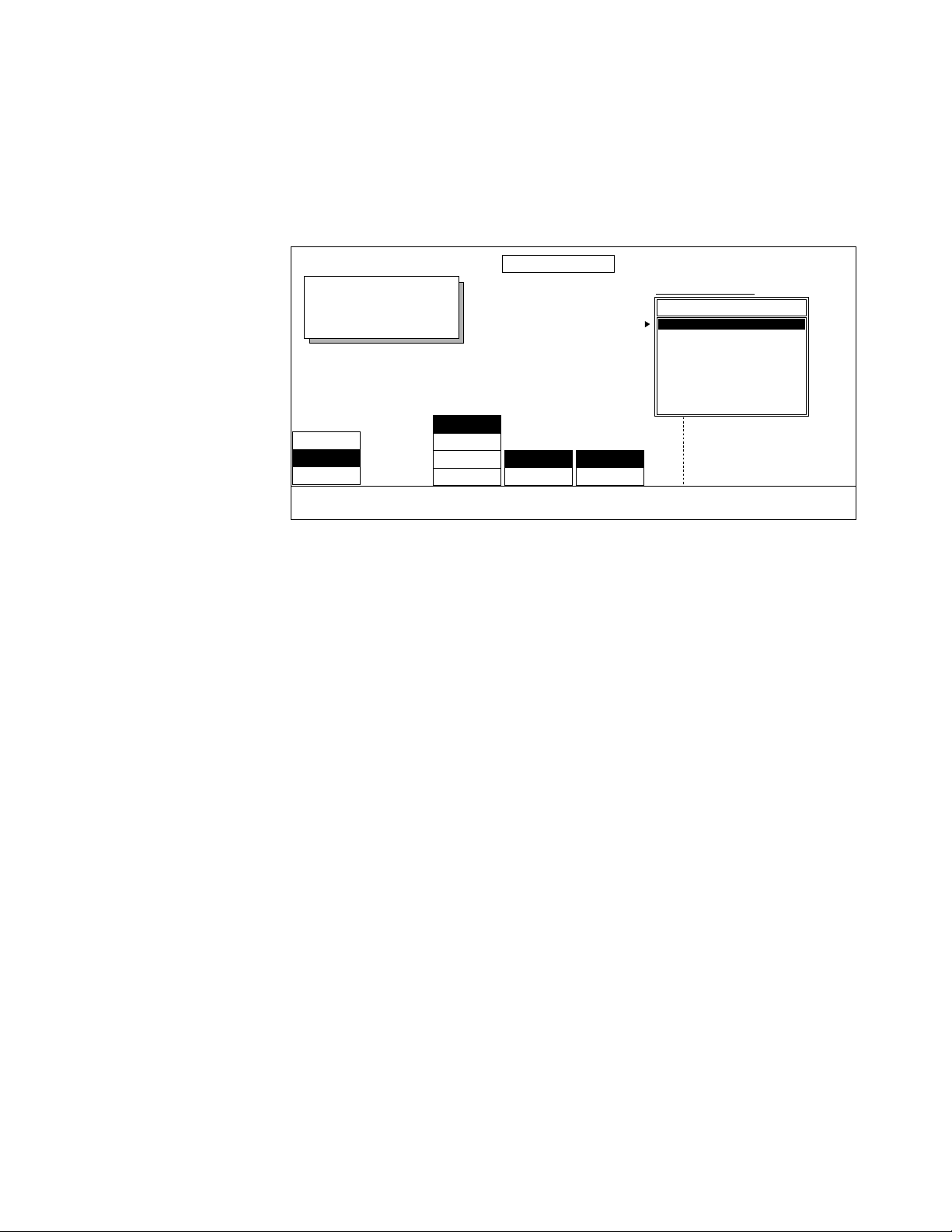
GPI Preferences
Use this menu to select a GPI and a function to cause that function to occur
when the selected GPI is activated. Select OFF in the GPI Input Options box
to disable a GPI.
EXT CONTROL PREFS
Displayed:
Register:
Keyframe:
Cur.Time:
PORTS
GPI INPUTS
DEFAULTS
MODIFY
GPI 1
GPI 2
GPI 3
GPI 4
ADJUST
HIGHLEVEL
LOWEDGE
TRIGGER ACTIVE
External Control Preferences Menu
GPI INPUT OPTIONS:
Function
Rewind
Run
Stop
Freeze
Reverse
Next KF
Prev KF
Rewind Jitter
SELECT/
SCROLL
PAGE
UP
PAGE
DOWN
GPI Preferences menu functions:
ADJUST — lets you choose each GPI (1 - 4) you will be assigning triggering
parameters.
TRIGGER — use to set whether the GPI trigger closure is determined by LEVEL
or
EDGE.
LEVEL — triggers the GPI closure when level is set high (in active-high)
or set low (in active-low). When
LEVEL is selected the pulse must have a
duration of at least 2 fields.
EDGE — triggers the GPI closure when a rising edge is detected. Only a
rising edge will cause GPI closure.
ACTIVE — this mode is only available when LEVEL has been selected as trigger
parameter. You choose whether the GPI triggers closure when it is
LOW.
HIGH or
Krystal 4300 Reference 3-5
Page 68

Section 3 — System Setup Menu
SCROLL/SELECT — use to scroll through and select GPI Input Options you
want to assign to a particular GPI. The following is a list of those options.
You can also use the
that function using the
■ Rewind
■ Run
■ Stop
■ Freeze
■ Reverse
■ Next KF
■ Prev KF
■ Rewind Jitter
■ Step Jitter
■ Fade
SCROLL soft knob to scroll through the list then select
SCROLL/SELECT soft button.
■ Advance Frame
■ Reverse Frame
■ Advance Field
■ Reverse Field
■ Off — disables GPI
PAGE UP, PAGE DOWN — use these two soft buttons to scroll to option choices
out of view in the scroll pane.
3-6 Krystal 4300 Reference
Page 69

Defaults Preferences
Use this menu to define how your external control preferences are defined
and recalled.
EXT CONTROL PREFS
Displayed:
Register:
Keyframe:
Cur.Time:
PORTS
GPI INPUTS
DEFAULTS
MODIFY
External Control Preferences Menu
DEFINE
XTL PREFS...
RECALL
XTL PREFS...
RECALL GVG
DEFAULTS...
Defaults preferences menu functions:
DEFINE XTL PREFS... —saves your current external default preferences as
your user defaults.
RECALL XTL PREFS... — recalls you user external defaults to your current
preferences.
RECALL GVG DEFAULTS... — recalls GVG’s factory defaults to your current
preferences.
Krystal 4300 Reference 3-7
Page 70

Section 3 — System Setup Menu
Run Preferences Menu
Press the System Setup top menu button then press RUN PREFS> to bring up
the following menu.
Use this menu to access controls that set the run starting field (Any Field,
Odd, or Even). Normally, effects are started at the beginning of any field.
However, it may be desirable to delay the start of the effect until the next
occurrence of an
specify the field where the start of an effect will occur.
RUN PREFS
Displayed:
Register:
Keyframe:
Cur.Time:
ODD or EVEN field. Pressing STARTING FIELD allows you to
ANY FIELD
ODD
EVEN
STARTING
FIELD
DEFINE
RUN PREFS
RECALL
RUN PREFS
RECALL GVG
DEFAULTS...
Run Preferences menu functions:
STARTING FIELD — effect may start at:
ANY FIELD allows effect to start at any field.
ODD allows effect to start on the next ODD field.
EVEN allows effect to start on the next EVEN field.
DEFINE RUN PREFS... — saves your current run preferences as your user
defaults.
RECALL RUN PREFS... — recalls user defaults to your current run preferences.
RECALL GVG DEFAULTS... — recalls factory defaults to your current run pref-
erences.
3-8 Krystal 4300 Reference
Page 71

Panel Configuration Menu
Use this menu to assign the panel to a suite, set the IP and subnet mask
addresses and as access to the panel diagnostics and calibrate mode.
PANEL CONFIGURATION
Displayed:
Register:
Keyframe:
Cur.Time:
Panel Configuration Menu
SUITE
ASSIGN...IPADDRESS...
SUBNET
MASK...
DIAGS>CALIBRATE
>
RECALL
NV RAM...
RECALL GVG
DEFAULTS...
SUITE ASSIGN — Assigns the panel to one of the four suites.
IP ADDRESS — This is a system administration function, please see the
Krystal Installation and Service manual for information on this function.
SUBNET MASK — This is a system administration function, please see the
Krystal Installation and Service manual for information on this function.
DIAGS — This is a system administration function, please see the Krystal
Installation and Service manual for information on this function.
CALIBRATE — This is a system administration function, please see the
Krystal Installation and Service manual for information on this function.
RECALL NV RAM... — This function recalls the last user-defined panel config-
uration settings.
RECALL GVG DEFAULT — Recalls GVG default panel configuration.
Krystal 4300 Reference 3-9
Page 72

Section 3 — System Setup Menu
System Configuration Menu
The System Configuration menus contain tools that are generally only used
during initial system installation, when the system hardware or software is
being modified or upgraded, or when the system is being maintained. The
following warning appears when you select
CAUTION Improper use of system administration tools may drastically inhibit Krystal’s
functionality.
System Configuration menus include:
■ Channel Configuration
■ Effect Manager Configuration
■ Source Select Device Manager
■ Suite Configuration
■ Network Configuration
■ Save/Load
SYSTEM CONFIG> :
These menus are covered in detail in the separate Krystal Installation and
Service Manual.
3-10 Krystal 4300 Reference
Page 73

User Tools Menu
Introduction
The User Tools Menu lets you customize the operating parameters of the
Krystal system to suit your particular operating style including: Source
Memory, Work Buffer Preferences, Display Options (including Screen
Saver), and the Edit Enable function.
Section 4
Press the
User Tools Top Menu button to bring up the following menu.
USER TOOLS
Displayed:
Register:
Keyframe:
Cur.Time:
ON
OFF
SOURCE
MEMORY >
WORK BUF
PREFS >
DISPLAY
OPTIONS >
PANEL
PREFS >
EDIT
ENABLE
Lower level menus included in this menu include:
SOURCE MEMORY> — this menu determines the relationship of source-
related parameters with a source. You can lock or unlock source-related
parameters to their sources.
WORK BUF PREFS> — this menu allows you to define the Krystal Unity KF,
(user defined default effect parameter values), and recall GVG default
effect parameter values.
Krystal 4300 Reference 4-1
Page 74

Section 4 — User Tools Menu
DISPLAY OPTIONS> — this menu determines which timeline displays are
cycled through on the Panel’s Menu Display when you press the
top menu button. The Screen Saver function is enabled and disabled from
this menu.
PANEL PREFS> — this menu sets up the panel warnings, lamp intensity, joy-
stick deadzone, and clip options. It also allows you to set the panel to GVG
default values for these parameters.
EDIT ENABLE — enables or disables the panel buttons used to edit effects.
Each menu is discussed in detail on the following pages.
Source Memory Menu
The Source Memory menu determines the relationship of source memory
parameters with a source. Source memory parameters include:
■ Video Source Selection with associated Key and/or Mask Selection
Timeline
■ All Key Settings (External, Self, or Off, Clip Low, Clip High, Offsets)
■ All Mask Settings (Internal, External, Pattern Selection)
■ Coring
■ Motion Detection
■ H/V Reverse
■ Matte Fill
■ Input Video Shaping
■ Enhanced Image Fidelity Option (On or Off)
Source memory parameters and source selections are keyframable and
appear on the source memory timeline. All source memory parameters
follow the video source selection if source memory is locked.
Source memory parameters follow both the channel delegation and the
Near/Far delegation. This makes it possible to apply different source memories to the front and back sides of the manipulated picture.
4-2 Krystal 4300 Reference
Page 75
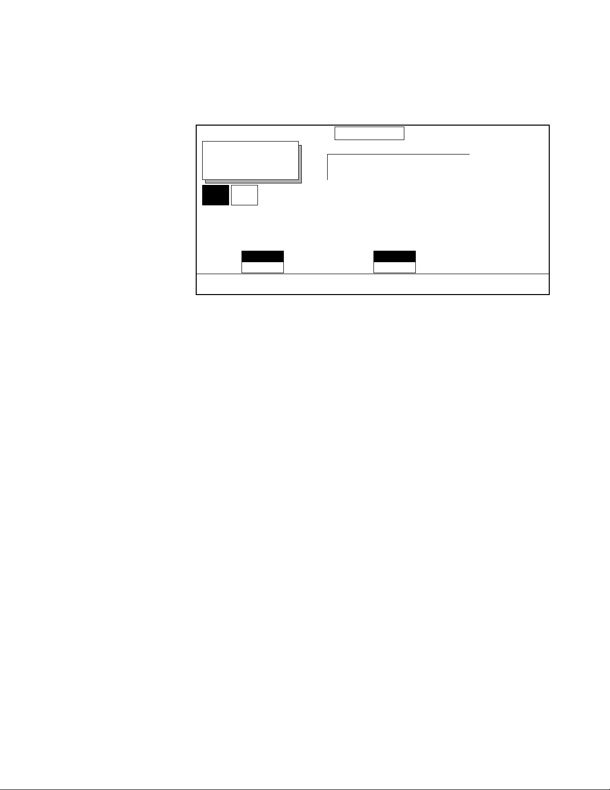
Source Memory Menu
Press the User Tools Top Menu button and then press SOURCE MEMORY > to
bring up the following menu
.
SOURCE MEMORY
Displayed:
Register:
Keyframe:
Cur.Time:
Near Far
FRONT SIDE
Video: 1
Key: 1
Mask: 1
back side
Video: 2
Key: 2
Mask: 2
ON
OFF
SRC MEM
LOCKED
DEFINE
EFF SEND...
CURRENT
ALL
SRC MEM
UNITY
DEFINE
UNITY...
RECALL
UNITY...
RECALL GVG
DEFAULTS...
Source Memory menu functions:
SRC MEM LOCKED — ON or OFF.
ON — locks source memory parameters to their sources. This is the
normal mode of operation for source memories. In this mode, when a
new video source is selected for an input (for example, assigning
Source 1 to Channel 1’s video input), the source memory associated
with the new video source will become the current active source
memory for Channel 1, meaning that the source memory for Source 1
will be copied into Channel 1’s work buffer.
OFF — unlocks source memory parameters from their source. Choose
OFF when you do not want the source memory to update automatically.
For example, you may want to try various sources with a given set of
source parameters. Now different sources may be selected either manually from a control point or by pulling them from keyframes, without
changing the active source memory.
DEFINE EFF SEND... — will copy the source memory settings for the delegated
side of the display channel to the Effects Send source memory. When the
Switcher is in Effects Send mode, the switcher performs all source selection
and the Krystal Effects Send source memory parameters will be used for all
the selected sources. When in Effects Send mode, the Front/ Back Side text
at the top of the Krystal display indicates this mode is activated for the delegated channels.
SRC MEM UNITY — the CURRENT or ALL settings affect the operation of DEFINE
UNITY, RECALL UNITY, and RECALL GVG DEFAULTS as follows:
Krystal 4300 Reference 4-3
Page 76

Section 4 — User Tools Menu
Current — If the near side and far side have different sources, DEFINE
UNITY will copy the source memory settings for each delegated side of
the display channel to the unities of these sources. If the same source is
on both the near and far side, then settings of the display side will be
copied to that source's unity. (If both sides are delegated, the one
pushed first is the display side.)
RECALL UNITY will copy the unity(ies) for
the delegated channels for the sources on the delegated sides to the
source memories for those sources.
RECALL GVG DEFAULTS will copy the
factory default settings to the source memories for the delegated channels and the delegated sides.
All —
DEFINE UNITY will copy all source memory settings for the display
channel to the respective source memory unities.
RECALL UNITY will copy
all the unities to all the source memories of the delegated channels.
RECALL GVG DEFAULTS will copy the factory default source memory to all
the source memories of the delegated channels.
Work Buffer Preferences Menu
Press the User Tools Top Menu button then press WORK BUF PREFS> to bring
up the following menu. Use this menu to set how Krystal uses information
in the current work buffer.
WORK BUFFER PREFS
Displayed:
Register:
Keyframe:
Cur.Time:
Work Buffer Preferences menu functions:
STORE WORK
BUFFER...
DEFINE
UNITY KF...
RECALL
UNITY KF...
RECALL GVG
DEFAULT...
STORE WORK BUFFER... — stores the current work buffer for further use.
Works with the
Restore Workbuffer Control Panel button.
4-4 Krystal 4300 Reference
Page 77

Work Buffer Preferences Menu
DEFINE UNITY KF... — stores the current work buffer settings for the display
channel (indicated in the top left corner of the screen) to the Unity KF for
use by the logical, global, and camera channels. Different Unity KF settings
are saved under the following conditions:
■ If a logical channel (1-4) is the display channel, all the display channel’s
settings (including transforms) will be saved to the Unity KF.
■ If a global channel is the display channel, only the global channel’s
transform settings will be copied to the Unity KF. Other existing Unity
KF parameters (borders, crops, etc.) will be retained.
■ If only the camera channel is delegated (and so is the display channel),
only the camera channel’s transform and combiner parameters (on
systems equipped with a combiner) will be copied to the Unity KF. This
is the only case where camera channel transforms are saved to the
Unity KF.
■ If the camera channel and one or more other channels are delegated,
and the camera channel is the display channel, the current combiner
parameters will be copied to the Unity KF, but transform settings will
be copied from the lowest numbered delegated logical channel or
global channel.
Note Unity KF values are applied to all channels, including Global and Camera chan-
nels. Transform values should be default when the Unity KF is defined, to
prevent multiple application of transforms when the Unity KF is invoked.
RECALL UNITY KF... — copies the stored Unity KF settings into the work
buffer(s) of all delegated channels.
RECALL GVG DEFAULTS... — copies factory defaults into the work buffer(s) of
all delegated channels.
Krystal 4300 Reference 4-5
Page 78

Section 4 — User Tools Menu
Display Options Menu
Use this menu to set which timeline displays are cycled through on the
Panel’s Menu Display when you press the
displays include: Master Timeline, Independent Timeline, Transform, and
Clipboard. You can also use this menu to enable or disable the Screen Saver.
Timeline top menu button. The
Press the
User Tools top menu button then select the DISPLAY OPTIONS>
submenu to bring up the following menu.
DISPLAY OPTIONS
ADD
SHOW:
Display Name
1. Master Timeline
2. Ind. Timelines
3. Transform
4. Clipboard
SELECT/
SCROLL
REMOVE
DISPLAY
SCREEN
SAVER...
SCROLL
DON'T SHOW:
Display Name
SELECT/
SCROLL
DISPLAY
SCREEN SAVER... — to activate the screen saver press this button. To deacti-
vate, simply press any button or move any knob on the Control Panel.
Follow these steps to choose which timelines display in the
Timeline menu
display.
1. Using the SELECT/SCROLL button or (SCROLL) Soft Knob, scroll to the
Display Name you wish to remove from the SHOW box.
2. Press REMOVE DISPLAY to take this selection out of the SHOW box and
place it into the DON’T SHOW box.
3. To add the selection back into the SHOW box, press ADD DISPLAY. All the
selections showing in the SHOW box will then be displayed in the
Timeline top menu.
4-6 Krystal 4300 Reference
Page 79

Panel Preferences Menu
Use this menu to set up specific panel preferences.
Press the User Tools top menu button then press PANEL PREFS> to bring up
the following menu.
PANEL PREFERENCES
Displayed:
Register:
Keyframe:
Cur.Time:
Panel Preferences Menu
ON
OFF
ERROR
WARNING
ON
OFF
KNOB END
WARNING
HIGH
MEDIUM
LOW LARGE LOW&HIGH
LAMP
INTENSITY
SMALL
MEDIUM
JOYSTICK
DEADZONE
CLIP
OPTIONS
RECALL GVG
DEFAULTS...
Panel Preferences menu functions:
The following functions are all saved in Panel NV RAM. You cannot save
them to disk.
ERROR WARNING — turns ON or OFF the warning beep that an erroneous entry
has been made with the keypad or an inactive button has been pressed.
Krystal must be expecting an entry from the keypad for the warning to
sound.
KNOB END WARNING — turns ON or OFF the warning beep that one of the four
knobs to the right of the display or the joystick has gone to one of its limits.
LAMP INTENSITY — sets the intensity of the panel lamps (HIGH, MEDIUM, LOW).
JOYSTICK DEADZONE — This feature is not currently implemented
CLIP OPTIONS — This feature is not currently implemented
RECALL GVG DEFAULTS — causes the factory default panel preferences settings
to become the active settings. These parameters were set at the factory and
are not changeable.
Krystal 4300 Reference 4-7
Page 80

Section 4 — User Tools Menu
Edit Enable Function
The EDIT ENABLE mode located in the User Tools Top Menu shown below, is
where you enable or disable the Krystal Control Panel buttons used in
effects editing.
USER TOOLS
Displayed:
Register:
Keyframe:
Cur.Time:
SOURCE
MEMORY >
WORK BUF
PREFS >
DISPLAY
OPTIONS >
PANEL
PREFS >
ON
OFF
EDIT
ENABLE
The Krystal panel is always in one of two Edit Enable Modes:
■ ON — when selected, operations are allowed to create and modify
effects. The Control Panel buttons associated with editing go low tally
when on.
■ OFF — when off, this setting protects effects from accidental modifica-
tion (which could spell disaster during a live production). You cannot
perform any edit operations in the OFF mode. All edit button tally
lights will be off.
4-8 Krystal 4300 Reference
Page 81

Section 5
File Operations/Macro Menus
Introduction
The Krystal system includes a file manager for saving and loading system
data to and from floppy disks. This section describes how to use the Krystal
file manager. Macro operations are also described in this section.
File Operations Menu
The File Operations menu is accessed by pressing the File Oper. top menu
button to bring up the menu shown below:
FILE OPERATIONS
Displayed:
Register:
Keyframe:
Cur.Time:
SAVE/
LOAD >
DISK
MANAGER >
Saving and Loading Files
Effects, system configuration, and macro data can be saved to and loaded
from a floppy disk. Effects may be saved as single entities or as a combined
file. Macros can also be saved individually or combined.
REGISTER
OPER. >
CHANNEL
OPER. >
PANEL
PREFS >
NAME
EFFECT...
Krystal 4300 Reference 5-1
Page 82

Section 5 — File Operations/Macro Menus
Press SAVE/LOAD from the File Operations menu to display a Save/Load
menu similar to that shown below:
SAVE/LOAD
EFFECT
SYS CFG
USER PREF
PANEL CFG
MACRO
FILE
TYPE
EFFECTS REGISTERS:
Effect Name
ALL
ALL Separate
00. Register 0
01. Register 1
02. MORNING
03. DEW
04.
05. CASSIDY
SELECT/
SCROLL
SAVE... SELECT/
LOAD... PAGE
/floppy
File Name Type
1. REGISTER.KFX Effect
2. REGISTER.K00 Effect
3. REGISTER.K01 Effect
3. CHINA.K72 Effect
4. CAT.K73 Effect
5. SUN.K74 Effect
6. FLOWER.K75 Effect
DELETE
FILE...
SCROLL
UP
SCROLL
PAGE
DOWN
Save/Load menu functions include:
FILE TYPE allows you to select the type of files you plan to save or load.
EFFECT — sets the current list of effect registers to be displayed on the
left side of the SAVE/LOAD menu. Empty registers are displayed as
blank in the scroll pane.
■ An individual effect register or file can be selected to be saved or
loaded by choosing the effect or file name in the scroll panes.
■ All the Krystal registers can be saved and loaded as a combined file
(.KFX extension) by selecting
ALL in the EFFECTS REGISTERS scroll
pane.
■ All the Krystal registers can be saved and loaded as individual files
by selecting
ALL Separate in the EFFECTS REGISTERS scroll pane.
SYS CFG — sets the current list of system configuration categories to be
displayed on the left side of the SAVE/LOAD menu. Different types of
configuration data can be saved individually, or this data can be saved
and loaded as a combined file.
CAUTION The “NETWORK” and “ALL” configuration data selections contain network IP
address information. Loading these configuration files will make the entire
Krystal system reset, which will affect any current Krystal operations. The “ALL
SYSTEM DATA” selection does not contain network data and so will not cause
a system reset when loaded.
USER PREF — sets up the user preferences to be saved or loaded.
PANEL CFG— sets up the panel config parameters to be saved or loaded.
MACRO— sets up the macros to be saved or loaded.
5-2 Krystal 4300 Reference
Page 83

File Operations Menu
SELECT/SCROLL button is used to scroll to and select an item in the active
scroll list.
SCROLL soft knob is used to scroll to and select an item in the active scroll
list.
SAVE... is used to save the selected item to floppy disk. You will be
prompted for a file name of up to 8 characters. An effect’s current name will
be displayed as the default name for the file. The default file name will be
truncated to 8 characters, invalid DOS characters will be removed, and
reserved DOS words (i.e. PRN, AUX, CON will be changed to “EFFECT”).
The item is saved as an ASCII file. If a file with the same name already
exists, you will be asked to verify the command.
LOAD... is used to load the selected item from floppy disk to the Krystal
system. You will be prompted to verify the action. Previous contents of the
destination being loaded to will be overwritten. Reloaded register files
display their complete effect names even if the file name was truncated
when saved. When loadingindividual register files, be sure to select the
desired Krystal register in the EFFECTS REGISTERS list before you load
the selected file from disk. Register files can be saved to any register
number. A single register file can be loaded to the register it came from by
selecting the individual effect file in the right scroll pane and selecting
ALL
in the EFFECTS REGISTERS list before loading the file from disk. When
loading
ALL or ALL Separate, Krystal registers not represented on the floppy
disk are not overwritten.
DELETE FILE... is used to delete an individual file selected in the right scroll
pane from the floppy disk.
Krystal 4300 Reference 5-3
Page 84

Section 5 — File Operations/Macro Menus
Disk Manager Menu
Use the Disk Manager Menu to format floppy disks. Press the
File Oper. top menu then press the DISK MANAGER > menu button to bring up
the following menu:
DISK MANAGER
Displayed:
Register:
Keyframe:
Cur.Time:
1.44 MB
DISK
TYPE
FORMAT
DISK...
SAVE ERR
LOG...
Disk Manager menu functions:
DISK TYPE — 1.44 MB density is the only selection.
FORMAT DISK... — Press this soft button to format a floppy disk. A dialogue
box will appear. You can then press CANCEL to get out of the formatting
loop or you can press OK to proceed with the formatting operation.
SAVE ERR LOG... — This function lets you dump a log of system errors (plain
ASCII text in MS-DOS format) onto a disk for print out on your pc. A dialogue box will appear. You can press CANCEL to get out of this operation
or you can press OK to proceed with the Save Error Log operation.
5-4 Krystal 4300 Reference
Page 85

Register Operations Menu
Register Operations allow you to move Krystal keyframe data from one
register to another, and permits you to delete data from Krystal registers.
Register operations require that an Effect Manager be acquired and on-line.
If an Effect Manager is not acquired or on-line, registers operations will not
occur and no message will be displayed.
File Operations Menu
The Register Operations menu is accessed by pressing the
menu button, and then pressing the
REGISTER OPER.> soft button.
File Oper. top
REGISTER OPERATIONS
Displayed:
Register:
Keyframe:
Cur.Time:
COPY
SWAP
ERASE
APPEND
MOVE
OPERATION
BLOCK
SINGLE
AFFECTED
REGISTERS
To Copy register 1 to register 2, press Copy.
Effect Name Channels Used Effect Duration
00. Register 0 1 . . . . G1 C 3:00
01. Jack 1 2 3 4 G1 C 5:00
02. Straw 1 2 3 . C 2.15
03. Wichitah 1 2 3 4 G1 G2 C 1:00
04. Other 1 1 . . . G1 C 2:00
05. Playing 2 . . . G2 C 3:00
06. In Band 3 . . . C 4:00
07. . . . . . . . 0:00
08. . . . . . . . 0:00
09. . . . . . . . 0:00
KEYPAD
ENTRY
PAGE
UP
PAGE
DOWN
SCROLL
COPY...
The register scroll pane is for display of register data only. No selections can
be made in the scroll pane. Instead register numbers are entered using the
Krystal Control Panel keypad.
The KEYPAD ENTRY soft button readies the keypad for entry of a “from” register number.
Copy, Swap, Erase, Append, and Move register operations are supported.
Copy
The Copy function copies keyframe data from one register or block of registers to another register or block of registers. The original data remains
unaffected. To copy register data from the Register Operations menu:
1. Select COPY with the OPERATION soft button.
2. Select whether you want to copy a SINGLE register or a BLOCK of registers
with the
3. Enter the register(s) to copy from by pressing the register number in the
keypad followed by the
the case of copy block, the first register number to copy to) in a similar
manner.
Krystal 4300 Reference 5-5
AFFECTED REGISTERS soft button.
Enter button. Enter the register to copy to (or, in
Page 86

Section 5 — File Operations/Macro Menus
4. Execute the function by pressing COPY.... After the function completes,
a message appears at the top of the screen indicating whether the
operation was successful.
A “.” may be entered for the “to” register. This will effectively enter the
number of the next empty register.
When a copy block is requested, the operation will not be performed if the
“to” block does not have enough registers to fit all of the “from” block nor
if the “to” and “from” blocks overlap. In these cases an error message will
be displayed.
If the register numbers for the “from” block are entered in descending
order, the registers will copy in reverse order. For example, if the request is
made to copy registers 5 through 1 to register 10, register 5 will be copied
to register 10, register 4 to 11, etc. When the operation has completed, the
message “REVERSE OP DONE” will display.
If the register(s) being copied “to” are not empty, a warning message will
display that requires an OK/Cancel response. If OK is chosen, the register(s) being copied “to” will be deleted, and the “from” register(s) will be
copied to the “to” registers.
Swap
Erase
Append
The Swap function exchanges keyframe data between two registers. The
data being exchanged is removed from its source register and is copied to
its destination register. To swap register data, use the same procedure as the
Copy function, except select
no query is done if there are non-empty registers involved in the operation.
The Erase function removes keyframe data from a single register, a block of
registers, all registers, or the current register. To erase register data, use the
same procedure as the Copy function, except select
either
When an Erase operation has been requested, a warning message will
display and will require an OK/Cancel response.
The Append function adds keyframe data from one register to the end of
the effect in another. To append register data, use the same procedure as the
Copy function, except select
SINGLE, BLOCK, ALL, or CURRENT affected registers.
SWAP. The operation is similar to Copy, except
ERASE, and then select
APPEND.
Requesting an append from an empty register has no effect. Requesting an
append to an empty register will do a Copy register operation.
5-6 Krystal 4300 Reference
Page 87

Move
File Operations Menu
The Move function moves keyframe data from one register to another. To
move register data, use the same procedure as the Copy function, except
select
MOVE.
Warnings and errors are the same as in the Copy operation.
Krystal 4300 Reference 5-7
Page 88

Section 5 — File Operations/Macro Menus
Channel Operations Menu
The Channel Operations feature allows the user to move keyframe data
from one channel (or wireframe) to another in the current effect, and
remove data from a channel. Copy, Swap, Delete, and Move channel operation functions are supported.
When data from a physical or wireframe channel is copied, swapped, or
moved to a Global or Camera channel, any non-transform data that may
exist will not be transferred. If the operation will result in the loss of this
data, the system will ask if the user wants to continue before it performs
this operation.
Illogical channel operations (for example, copying the same information to
and from the same channel) will be ignored.
Channel operations require that an Effect Manager be acquired and on-line.
If an Effect Manager is not acquired or on-line, channel operations will not
occur and no message will be displayed.
Undo is not supported at this time. However, the clipboard is not affected
by channel operations. You can copy and paste channel information to the
clipboard, perform your channel operation, and recover the original clipboard data if necessary.
Copy
The Channel Operations menu is accessed by pressing the
menu button, and then pressing the
CHANNEL OPER. > soft button.
File Oper. top
CHANNEL OPERATIONS
Displayed:
Register:
Keyframe:
Cur.Time:
COPY
SWAP
DELETE
MOVE
OPERATION AFFECTED
ALL
SELECTED
TIMELINES
Copy All Function TLs from Channel 1 to Channel 2
From:
1. Channel 1
2. Channel 2
3. Channel 3
4. Channel 4
5. Global 1
6. Global 2
7. Camera
SELECT/
SCROLL
To:
1. Channel 1
2. Channel 2
3. Channel 3
4. Channel 4
5. Global 1
6. Global 2
7. Camera
SELECT/
SCROLL
SCROLL
COPY...
The copy function copies keyframe data from one channel to another
channel in the current effect. The data in the original channel remains unaffected.
5-8 Krystal 4300 Reference
Page 89

File Operations Menu
To copy channel data from the Channel Operations menu:
1. Select COPY with the OPERATION soft button.
2. Select whether you want to copy ALL or only the SELECTED timelines with
the
AFFECTED TIMELINES soft button.
3. Select the channel to copy “From:” using the SELECT/SCROLL soft button
and/or the
SCROLL soft knob, and select the channel to copy “To:” in a
similar manner.
4. Execute the function by pressing COPY... . After the function completes,
a message will appear at the top of the screen to notify the user whether
or not the operation was successful.
When a copy channel operation is executed with ALL Affected Timelines
chosen, all function timelines in the channel being copied to are deleted. All
active function timelines are then copied between the chosen channels. If
there are no active function timelines in the “From:” channel, no action is
performed and a message is displayed.
Swap
When a copy channel operation is executed with SELECTED Affected
Timelines chosen, any function timelines in the channel being copied to
that are same as those currently selected in the other channel are deleted.
The selected timelines in the channel being copied from are then copied to
the other channel. Note that any selected function timelines on the channel
being copied to are ignored. If there are no selected function timelines in
the “From:” channel no action will be performed and a message is displayed.
The swap function exchanges keyframe data between two channels in the
current effect.
To swap channel data, use the same procedure as the copy function except
select the SWAP operation. The left channel selection scroll pane will indicate “Swap:”, and the right pane will indicate “With:”.
If you use SELECTED Affected Timelines for a swap operation, you can
select the timelines on either channel involved in the swap. Data will be
exchanged if an active function is selected on only one of the channels.
Also, if a timeline selected for swapping on one channel is not present on
the other channel, a Move of that timeline data will be performed. The data
will be copied to a new timeline for that channel and the original channel’s
timeline data will be removed. If no data is selected on either channel an
error message will be displayed.
When a swap channel operation is executed, the data being exchanged is
removed from its source channel and copied to its destination channel.
Krystal 4300 Reference 5-9
Page 90

Section 5 — File Operations/Macro Menus
Delete
The delete function removes keyframe data from a channel in the current
effect. No message will be displayed indicating data will be lost.
To delete channel data, use the same procedure as the copy function except
select the DELETE operation. The left channel selection scroll pane will
indicate “From:” and the right selection scroll pane does not appear. If you
use SELECTED Affected Timelines for a delete operation, only the selected
timelines on that channel will be deleted.
Move
The move function moves keyframe data from one channel to another in
the current effect.
Timeline data will be lost from the channel that data is being moved to if
ALL is chosen. Timeline data will also be lost if SELECTED is chosen and
the incoming data includes timelines present in the channel the data is
being moved to.
To move channel data, use the same procedure as the copy function except
select the MOVE operation. Note that any selected function timelines on
the “To:” channel are ignored. If there are no selected function timelines in
the “From:” channel no action will be performed and a message is displayed.
When a move channel operation is executed, the timelines involved in the
action are deleted from the “To:” channel, the timelines in the “From:”
channel are copied to the “To:” channel, and then the original timelines in
the “From:” channel are deleted.
5-10 Krystal 4300 Reference
Page 91

Name Effect
File Operations Menu
To name or rename an effect, press the NAME EFFECT... button from the File
Operations menu. Since every register has a default name, you will be
prompted to edit the name of the current effect register.
FILE OPERATIONS
Displayed:
Register:
Keyframe:
Cur.Time:
Rename Effect....
Name:
Register0
lock
shift
1234567890
QWERT Y UI OP
ASDFGHJKL
ZXCV
BNM. /
space
_
del
return
shift
SCROLL
SAVE/
LOAD >
DISK
MANAGER >
CURSOR
LEFT
CURSOR
RIGHT
SPACE
OKBACK
CANCEL NAME
EFFECT...
Keep in mind that effects saved to files on disk are limited to 8 characters
for a file name. However, when calling up existing effect register names,
they will show in their entirety up to 32 characters.
Krystal 4300 Reference 5-11
Page 92

Section 5 — File Operations/Macro Menus
Macro Control Menu
Krystal lets you record up the 12 Macros (Macro 1-6 and Macro Shift 1-6).
Each macro can contain up to 100 steps. These macros can then be saved to/
from disk using the
You can save and load macros to and from floppy disk when the Panel is
not connected to an Effect Manager.
SAVE/LOAD menu located in the File Operations Top Menu.
Macro Record
Press the
Macro Top Menu button to bring up the menus shown below. The
Record menu is used for creating new macros. The Play menu is used for
menu driven playback of macros. Either menu can be used to delete and
rename macros.
To delete a macro, scroll to the desired macro you wish to delete until highlighted then press the
DELETE MACRO... soft button to delete the selected
macro.
To Rename a selected macro, press the
RENAME MACRO... soft button to bring
up the keyboard dialogue box, with which you can enter the new name.
MACRO CONTROL
MACRO LIST:
Key Name
1. [ 1] MACRO1
2. [ 2] MACRO2
3. [ 3] MACRO3
4. [ 4] DARK
5. [ 5] STAR
6. [ 6] empty
7. [S7] empty
8. [S2] empty
PLAY
RECORD
MACRO
MODE
BEGIN
RECORDING...
SELECT/
SCROLL
RENAME
MACRO...
DELETE
MACRO...
PAGE
UP
SCROLL
PAGE
DOWN
Perform the following steps to record a marco:
1. Highlight RECORD by pressing the MACRO MODE soft button.
2. Use the SELECT/SCROLL soft button to choose which macro in the Macro
List you wish to record into. The Macro List box shows up to 8 macros
at a time. The downward arrow indicates more choices are available out
of view. Use the
selections into and out of view. Use can also use the
PAGE UP and PAGE DOWN soft buttons to bring more
SCROLL soft knob to
scroll through the macro list.
5-12 Krystal 4300 Reference
Page 93

Macro Play
Macro Control Menu
3. Press the BEGIN RECORDING soft button which will bring up a keyboard
dialogue box in the menu display. You use this to name your macro.
You can use up to 15 characters for the macro name. Press OK when
finished naming the macro.
4. The Macro top menu button will flash while recording is taking place
and a dialogue box appearing in the menu display area will prompt
you to “Press the
Macro button again to stop recording”. After you have
pressed this button as directed, your macro will be completed and the
Macro button will stop flashing and return to high tally.
To playback a macro from the Krystal Control Panel, simply press the
yellow numbered
Macro button used to create the macro. Use the Macro
shift button to access macros 7-12.
You can also play a macro from a Qwerty Keyboard by pressing CTRL plus
one of the twelve function keys that map to the 12 macros (Macro 1-6 and
Macro Shift 1-6). For example CTRL, F1 plays Macro 1.
MACRO CONTROL
MACRO LIST:
Key Name
1. [ 1] MACRO1
2. [ 2] MACRO2
3. [ 3] MACRO3
4. [ 4] DARK
5. [ 5] STAR
6. [ 6] empty
7. [S7] empty
8. [S2] empty
PLAY
RECORD
MACRO
MODE
BEGIN
PLAYBACK...
SELECT/
SCROLL
RENAME
MACRO...
DELETE
MACRO...
PAGE
UP
SCROLL
PAGE
DOWN
To playback a macro using the Krystal Macro Control menu, perform the
following steps:
1. Toggle to the PLAY mode using the MACRO MODE soft button.
2. Scroll to the desired macro shown in the Macro List box.
3. Press the BEGIN PLAYBACK soft button to play the macro. The small box at
the top center of the menu display will say “Macro Complete” when
playback is finished.
Krystal 4300 Reference 5-13
Page 94

Section 5 — File Operations/Macro Menus
5-14 Krystal 4300 Reference
Page 95

Run Control Menu
Introduction
From the Run Control menu you can set pauses for running effects. From
this menu can also access the Path Control menus, where you can control
the path behavior of effects.
Press
Run Control to bring up the following menu.
RUN CONTROL
Displayed:
Register:
Keyframe:
Cur.Time:
Section 6
PATH
CONTROL >
PAUSE
CONTROL >
LOOP
CONTROL >
Run Control menu functions:
PATH CONTROL — controls the trajectory and rate of change of effect param-
eters between keyframes.
PAUSE CONTROL — pauses an effect at a specific time in the effect.
LOOP CONTROL — allows modifying the running o f an effect by specifying
jumps from one effect time to another.
Krystal 4300 Reference 6-1
Page 96

Section 6 — Run Control Menu
Path Control Menu
The path an effect takes between keyframes is automatically defined by the
system according to a default for each path parameter. The Path menu
allows you to modify these default parameters through selection of specific
types of motion parameters on a keyframe-by-keyframe basis.
When you are in a menu that has associated path control, the
Path button
located in the User Assist area to the left of the display will show low tally.
This indicates you can press
Path to go to the Path Control menu for your
currently selected function. You can also double press the transform
Control Panel buttons to go directly to the Path Control menu for that transform.
If you are in a menu that does not have path controls associated with it,
pressing the
Path top menu button located in the User Assist subpanel area
will bring up the following menu.
PATH CONTROL
TRANSFORM TOOLS:
Function
1. ALL
2. locate
3. rotate
TRANSFRMS
PICTURE
FRAME
KEY/STENCL
VIEW
IN/OUTPUT
TOOL
CATEGORY
4. size
5. spin
6. persp
7. skew
8. post
SELECT/
SCROLL
PATH
MENU >
PAGE
UP
SCROLL
PAGE
DOWN
You use this menu to select the top menu tool category and individual function whose path parameters you wish to change.
Path Control menu functions:
TOOL CATEGORY — categorizes the path control available by the five top
menus and path associated with the Transformation buttons. The heading
above the SELECT/SCROLL dialogue box will change to match the
selected Tool Category.
6-2 Krystal 4300 Reference
Page 97

Path Control Menu
The following are the Tool Categories and their associated functions:
■ TRANSFORMS — ALL, locate, rotate, size, spin, perspective, skew, and
post- transform.
■ PICTURE — pseudo color, opacity, defocus, mosaic, input recursive,
output recursive.
■ FRAME — crop, border, kurl, corner pin
■ KEY STENCL — keyer setup, coring, mask, drop shadow emboss, defocus.
■ VIEW — lighting, perspective enhance, perspective blur.
■ IN/OUTPUT — matte fill, motion detection, background, combiner, com-
biner background
SELECT/SCROLL — use to scroll and select the function within the tool cate-
gory that you wish to apply path control. You can also use the
SCROLL soft
knob to scroll through the functions listed.
PATH MENU> — press this soft button to go to the path menu associated with
the selected function indicated in the SELECT/SCROLL dialogue box.
PAGE UP — use to scroll back up a page in the functions listed in the
SELECT/SCROLL dialogue box.
PAGE DOWN — use to scroll down a page in the functions listed in the
SELECT/SCROLL dialogue box.
Krystal 4300 Reference 6-3
Page 98
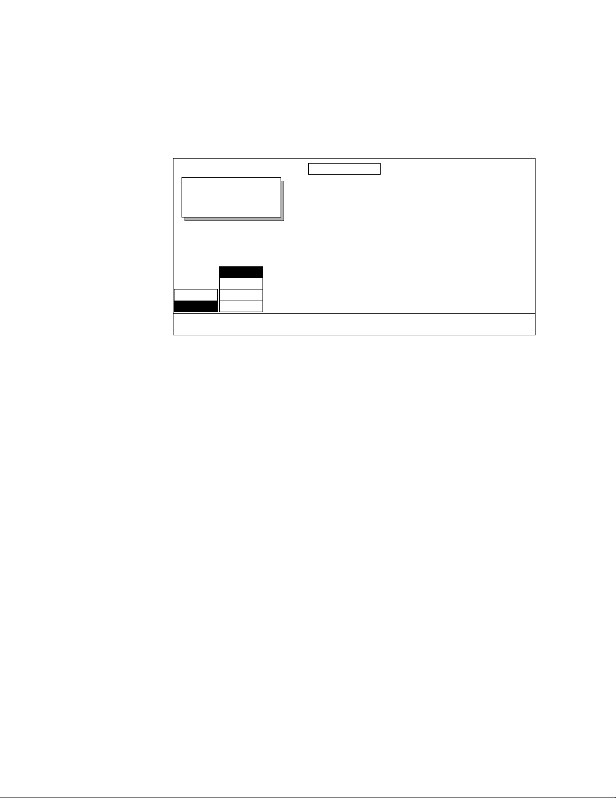
Section 6 — Run Control Menu
Transformation Path Control Menus
Krystal effects that require transformation path menus bring up the following soft buttons and soft knobs to let you control how your effect is
transformed. A typical Transformation Path control menu is shown below:
LOCATE PATH
Displayed:
Register:
Keyframe:
Cur.Time:
CURVE
SMOOTH
ON
OFF
HOLD PATH
LINEAR
S-LINEAR
TYPE
TENSION
0.0000
CONTINUITY
0.0000
BIAS
0.0000
The following soft button and soft knob controls are used with this menu:
HOLD — when ON, no motion interpolation occurs, which will make the key-
frame jump to the next keyframe location. The length of time that the effect
sits on each keyframe is set by the keyframe duration (default is 1 second).
PATH TYPE — path type selections are:
CURVE — causes a smooth and rounded path through the keyframe.
Paths are user adjustable via the soft knobs with path modifiers (tension, continuity, and bias) described below.
SMOOTH — This feature is not currently implemented. If selected, a
curve path with default values will be used.
LINEAR — applies a linear interpolation between keyframes; no acceler-
ation or deceleration is applied. Movement is mechanical having a constant velocity.
S-LINEAR — applies a linear or straight line motion between keyframes,
with acceleration and deceleration applied at the beginning and end of
each keyframe.
Tension, Continuity, and Bias Controls
When the CURVE parameter is selected, the three Soft Knobs provided are:
6-4 Krystal 4300 Reference
Page 99

Path Control Menu
TENSION — controls the length of the tension vector. At a setting of 0%,
this imaginary line extends an equal distance into and out of the keyframe, and the path through the middle keyframe is curved.
CONTINUITY — determines the angle of the path into and out of the key-
frame via the continuity path vector.
BIAS — determines whether the path will be “pulled” towards the pre-
vious or the following keyframe via the bias path vector.
Path Vectors
Tension Vector
KF1
Continuity Vector
–
KF3
–
KF2
+
+
Bias Vector
0865_14
With respect to a CURVE path between keyframes, each keyframe is made up
of three vector parameters as shown. See the separate Krystal User Manual
for background information and detailed explanations of the Tension, Continuity, and Bias path controls.
Krystal 4300 Reference 6-5
Page 100

Section 6 — Run Control Menu
All Transform Paths Menu
Selecting ALL from the Path Control Menu brings up the All Transforms
Paths menu. This menu lets you modify the paths for all the transform
parameters at that keyframe.
ALL TRANSFORM PATHS
Displayed:
Register:
Keyframe:
Cur.Time:
CURVE
SMOOTH
ON
OFF
HOLD PATH
LINEAR
S-LINEAR
TYPE
LOCATE values displayed.
TENSION
0.0000
CONTINUITY
0.0000
BIAS
0.0000
The current path for each transform parameter is viewed by pressing the
corresponding transform buttons located next to the joystick (
Rotate, Spin, etc.). Text appears on the menu indicating what transform
Size/Locate,
values have been assigned to the joystick and selected for display. When
Menu Ctrl, Locate Axis or Aspect is assigned, Locate parameter values will be
displayed. Menu items are gray for transforms that are not active in that
keyframe. You cannot affect the paths when an inactive transform is
selected (gray menu items). You must either assign an active transform to
the joystick, or make an inactive transform assigned to the joystick active
by changing it, before you will be able to apply a change to all the transform
paths for that keyframe.
Note The buttons in the All Transform Path menu must be pressed to affect a change.
Only Active and Changed transforms are affected by changes in this menu.
6-6 Krystal 4300 Reference
 Loading...