

Page 1
CameraMan
Student Robotic Camera System
Installation and Operation Manual
LPMCSC13 Rev B
1998
Page 2

Contacting Grass Valley
Region Voice Fax Address Web Site
North America (800) 547-8949
Support: 530-478-4148
Pacific Operations +852-2585-6688
Support: 852-2585-6579
U.K., Asia, Middle East +44 1753 218 777 +44 1753 218 757
France +33 1 45 29 73 00
Germany, Europe +49 6150 104 782 +49 6150 104 223
Copyright © Grass Valley. All rights reserved.
Grass Valley Web Site
The www.thomsongrassvalley.com web site offers the following:
Online User Documentation — Current versions of product catalogs, brochures,
data sheets, ordering guides, planning guides, manuals, and release notes
in .pdf format can be downloaded.
FAQ Database — Solutions to problems and troubleshooting efforts can be
found by searching our Frequently Asked Questions (FAQ) database.
Sales: (530) 478-3347
Support: (530) 478-3181
+852-2802-2996
Grass Valley
P.O. Box 599000
Nevada City, CA 95959-7900
USA
www.thomsongrassvalley.com
Software Downloads — Software updates, drivers, and patches can be down-
loaded.
Page 3
I. Meet Your Student System
▼ Congratulations on your Purchase. . . . . . . . . . . . . . . . . . . . . . . . . . . . . . 1
▼ Product Description . . . . . . . . . . . . . . . . . . . . . . . . . . . . . . . . . . . . . . . . 1
▼ System Components . . . . . . . . . . . . . . . . . . . . . . . . . . . . . . . . . . . . . . . 2
▼ PRM Jacks, Ports and Switches . . . . . . . . . . . . . . . . . . . . . . . . . . . . . . . . 3
II. Install Your Student System
▼ Mounting and Connecting the PRM
Mounting the PRMs . . . . . . . . . . . . . . . . . . . . . . . . . . . . . . . . . 4
Connecting microphones to the PRM . . . . . . . . . . . . . . . . . . . . 4
Connecting the PRM to the CameraMan . . . . . . . . . . . . . . . . . . 5
Connecting the Contact Closure Outputs. . . . . . . . . . . . . . . . . . 5
III. Configure Your Student System
▼ Configuring the Presets and Switches
Location Preset Configuration . . . . . . . . . . . . . . . . . . . . . . . . . . 6
Configuring the PRM. . . . . . . . . . . . . . . . . . . . . . . . . . . . . . . 6-7
▼ Setting up the Camera Control Keypad . . . . . . . . . . . . . . . . . . . . . . . . . . 8
IV. Use Your Student System
▼ Changing and Recalling Location Presets . . . . . . . . . . . . . . . . . . . . . . . . . 9
V. Appendices
▼ A: Troubleshooting . . . . . . . . . . . . . . . . . . . . . . . . . . . . . . . . . . . . . 10-11
▼ A: Specifications . . . . . . . . . . . . . . . . . . . . . . . . . . . . . . . . . . . . . . . . . 11
▼ C: Typical Student System Diagram . . . . . . . . . . . . . . . . . . . . . . . . . . . . 12
Page 4

Your new CameraMan Student Camera System takes the distance out of distance learning by combining the flexibility of your 1CCD or 3-CCD CameraMan camera with distributed preset control.
This manual covers the connection, configuration and use of your new Student Camera
System. It is designed to be used in conjunction with the Installation and Operations Manual
that came with your CameraMan General Pan/Tilt 1-CCD or 3-CCD camera, and the included
Camera Control Keypad Operations Manual. If you have any questions regarding the operation
of the keypad, or the connection, configuration or use of the camera, refer to that manual.
Youll see four icons in this manual:
This icon alerts you to important instructions in the operation and maintenance of
your Student Camera System.
This icon alerts you to tips or noteworthy suggestions in the operation, use or
maintenance of your Student Camera System.
This icon refers you to the 1-CCD General Pan/Tilt Camera installations and operations
manual that came with your camera.
This icon refers you to the 1-CCD or 3-CCD Camera Control Keypad installation and
operations manual.
Your Student Camera System should include
these components:
One 1-CCD or 3-CCD Camera Control Keypad
One Programmable Response Module
One Programmable Response Module Power Supply
One 10 CameraMan Communication Cable.
One CameraMan RS-485 Connector T
One 3 CameraMan Communication Cable.
One Student Camera System Operations Manual
One Camera Control Keypad Card (1CCD or 3CCD)
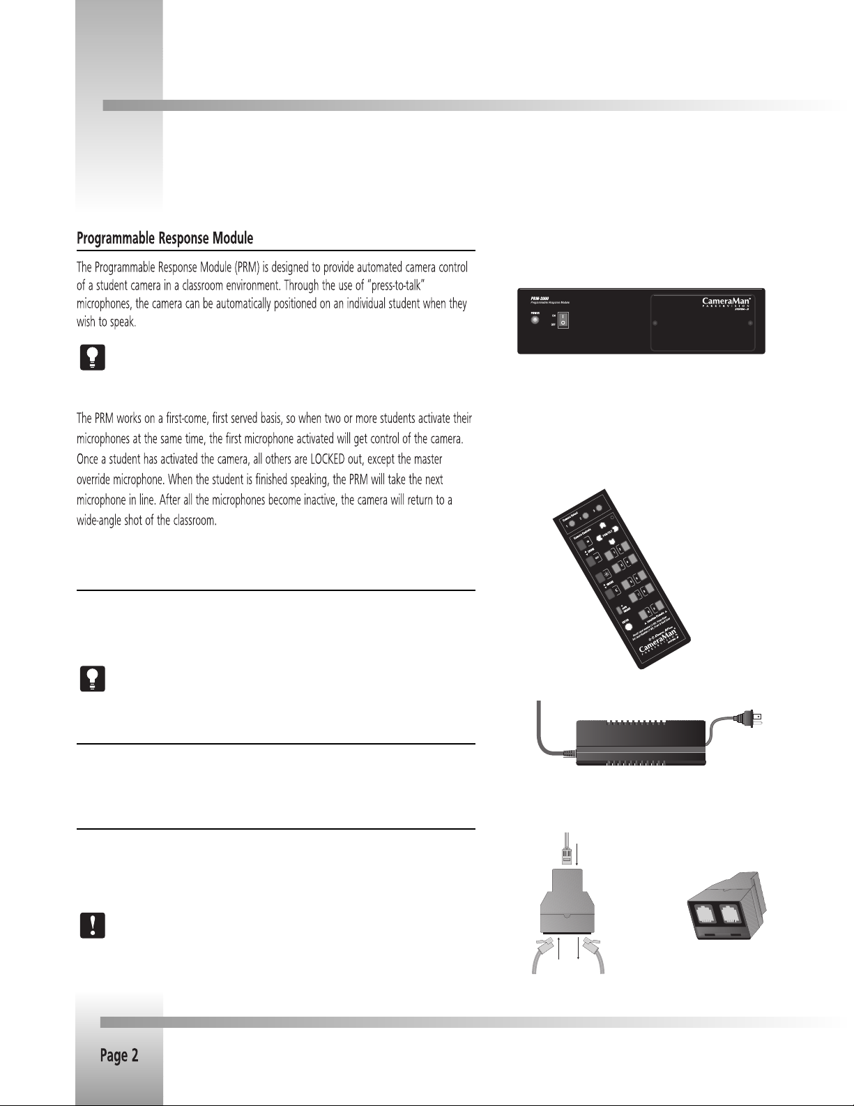
Product Description
The CameraMan Student Camera System is a robotic camera system with distributed preset
control used in distance learning applications. This system gives each student the power to be
instantly identified by the camera with the touch of a locator button on a microphone.
The Student Camera System can store up to 99 Location Presets, 33 of which are connected to
the Programmable Response Module. The 33 Student Locations are accessible through the
Low Profile Microphones and the Camera Control Keypad. The other 66 Location Presets are
only accessible through the Camera Control Keypad or the RS-232 interface.
In standard distance learning rooms, the camera is set to a wide-angle view of the classroom
throughout the lesson. This makes it difficult for instructors at the far-end to differentiate from
one student to the next and determine exactly which student is speaking. With CameraMan, each
individual student can simply press a locator button on a microphone when they want to speak.
The camera will then pan, tilt and zoom in on the individual student, magnifying their image.
When the student is finished speaking, the student simply lets go of the button and the
camera returns to a wide-angle view of the classroom.
This allows instructors at the far-end to identify each student individually and have face-to-face
interaction. Building these one-on-one relationships will enhance the overall learning process,
making distance learning more responsive and effective.
Page 1
Page 5
System Components
Your Student Camera System includes a Programmable Response Module, Power Supply, a 1-CCD or 3-CCD Camera Control Keypad,
and connection accessories. To set up your system, you will also need an audio mixer and microphones. These are not included
with your system.
Low Profile Microphones are recommended for better camera control.
“Voice-activated” microphones may pick up background noise and cause
unwanted camera motion.
Front of PRM with configuration plate
attached
1-CCD or 3-CCD
Camera Control
Keypad.
Camera Control Keypad
The included Camera Control Keypad gives you the ability to control the cameras pan and tilt
movement, focus, and IMAGE, as well as store and recall up to 99 camera presets (125 for 3CCD cameras).
See the included Camera Control Keypad Operations Manual for information on
setup, configuration and use of the keypad.
Power Supply
The Included Power Supply enables use with 120-240VAC, 50/60 Hz sources.
Power Supply
Connection Accessories
10 RS-485 CameraMan Communication Cable
CameraMan RS-485 T Connector
3 ft. RS-485 CameraMan Communication Cable
If you have purchased this as an upgrade, it will include all components except the
Camera.
left: top of
T-connector
with RS-485
cables.
right: front of
T-connector
Page 6
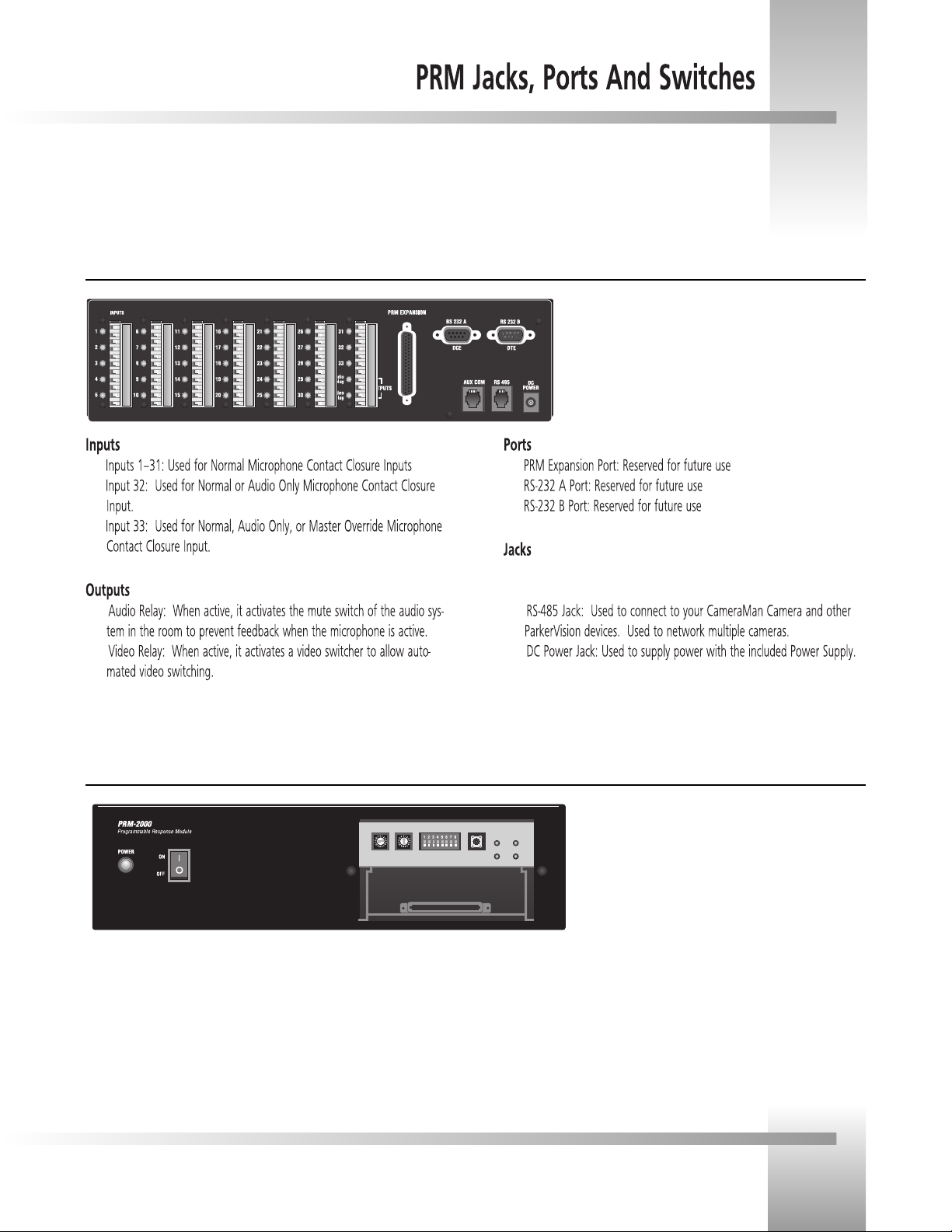
PRM Jacks and Ports (back)
?
?
?
?
?
?
?
?
?
AUX COM Jack: Provides communications to select perpiherals
and provides capability for future expansion.
?
?
PRM Configuration Panel (front with plate removed)
▼ Power Switch: Used Turn Power On.
▼ PRM Address Switch: 16-position rotary switch used to set the PRM
address which will reside on the RS-485 bus.
▼ Base Unit Address Switch: 16-position rotary switch used to tell the
PRM which camera it controls. It should match the Base Unit Address
switch on the CameraMan camera.
▼ DIP Switches: Used to configure the PRMs camera and microphone
control.
▼ Reset Button: Used to reset the PRM, but will not clear anycamera pre-
sets.
▼ Indicator Lights: Indicates communication activity.
Page 3
Page 7

Now you can begin to connect your Student Camera System components to your CameraMan camera, and audio equipment.
Mounting the PRM
1. Mount or place the Programmable Response Module in the desired location, being sure to
leave sufficient space to allow access to the connections on the back panel.
A rackmount is also available.
2. Verify that the switch on the front of the PRM is turned OFF.
3. Mount or place the PRM power supply in a convenient location near the PRM.
4. Plug the connector from the power supply cord into the DC POWER jack in the back of
the PRM.
5. Connect the other end of the power supply into a 100-240 VAC source.
The PRM Power Supply and CameraMan Power Supply should not be
interchanged.
PRM with included Power Supply
If you are using non-supplied “Y” cables, follow these instructions to connect
the 2-pin female Phoenix Connector wites to the greed connector block:
Phoenix
connector
to PRM
inputs
press-to-talk
microphone
Microphone Inputs on the
back of the PRM
+
-
+
-
Y cable
3-pin male
XLR to audio
mixer with
phantom
power (not
included)
cables with
negative (-)
and positive
(+) leads
Page 8

Mounting And Connecting The PRM
Connecting the PRM to the CameraMan
Using a 4-conductor cable, wired in a straight-through mode and terminated with modular
handset connectors, connect the RS-485 port on the back of the PRM to the
RS-485 port on the back of the CameraMan Camera.
Connecting the Contact Closure Outputs
The PRMs AUDIO RELAY and VIDEO RELAY contact closure outputs are activated when a
press-to-talk microphone button is pressed, and deactivated when the button is released.
Your specific application will determine how to connect these to your system.
AUDIO RELAY
The intended application of this relay is to activate the mute switch of the audio system in the
room to prevent feedback when the microphone is active. The relay activates and the contacts
close only when a microphone button is pressed. In a typical application, the Audio Relay
contact closure would connect to an amplifier or audio switcher.
VIDEO RELAY
The intended application of this relay is to activate a video switcher to select between various
video sources. The relay activates and the contacts close only when a microphone button is
pressed. When the contact relay is closed, there is a two second delay to allow time for camera
movement before the video is switched. In a typical application, the Video Relay contact
closure would connect to a video switcher.
To Connect the Audio, or Video Relay:
1. Connect one end of a 2-conductor cable to the green connector block:
Strip a short section (approximately 0.15) off the end of the wire
Insert the wire into the AUDIO RELAY or VIDEO RELAY screw terminal slot on
the connector block to the far right (the positive + lead is on top, the
negative - lead is on the bottom).
Tighten the terminal screw
2. Connect the other end of the cable to your audio equipment per their instructions.
PRM Audio and Video
Relay Outputs
PRM connected to CameraMan via RS-485 cable
Page 5
Page 9

Now that youve connected the Programmable Response Module to your CameraMan and microphones, you can begin configuring
the system. First, remove the configuration plate on the front of the PRM. Behind it, youll find the switches. On the back of the
configuration plate, youll find a diagram of the switches.
Location Preset Configuration
Your Student Camera System is capable of storing and recalling 99 location preset. The included
Camera Control Keypad is used to store a pan and tilt position, focus, zoom perspective, and
IMAGE control for each location preset. The microphones and keypad are used to recall them.
Camera Preset # Preset Type Recalled By
1-31 normal press-to-talk button
32 normal/audio only (see p.7) press-to-talk button
33 normal/option (see p.7) press-to-talk button
72 default all other student mics deactivated
34-71 and 73-99 set by user keypad location preset buttons
Close-up of student using press-to-talk microphone
Configuring the PRM
The PRM POWER switch should be turned OFF before changing any switches.
PRM Address
rotary switch
Base Unit Address
rotary switch
PRM ADDRESS:
This switch is used to set the address at which the PRM will reside on the RS-485 bus. This should
be set to an address that is unique to all devices (cameras, PRMs, etc.) in the system. By default,
this is set to C.
BASE UNIT ADDRESS:
This switch tells the PRM which camera it controls. Set this switch to correspond with the BASE
UNIT ADDRESS switch on the back of the CameraMan Student Camera (i.e.: If the cameras BASE
UNIT ADDRESS is set to 0, set the PRMs BASE UNIT ADDRESS switch to 0)
SET/ NO RETURN (DIP Switch 1):
PRM with Configuration Plate removed
DOWN (and all microphone inputs are inactive) The camera will return to a default preset
(preset # 72), which is usually set to be a wide shot of the room.
UP (and all microphone inputs are inactive) The camera will remain positioned at the last
active input.
RETURN TIME/ SETTING (DIP Switches 2,3):
Switches 2 and 3 only apply if Switch 1 is set to DOWN. They select the time delay associated
with the camera returning to the default preset after the last active microphone is released.
Use this chart to set the switches accordingly:
DIP switches
Switch 1 Switch 2 Switch 3 Time Delay
DOWN DOWN DOWN No Delay
DOWN UP DOWN 5 Second
DOWN DOWN UP 10 Second
DOWN UP UP 15 Second
Configuration settings printed on inside of configuration plate.
Page 10

Configuring The Presets and Switches
INPUT #32 OPERATION (DIP Switch 4):
This switch is used to determine the operation mode of input 32.
NORMAL The input will operate as a normal input, identical to inputs 1-31.
AUDIO The input will operate in an audio-only mode, which causes no camera
movement when the microphone is active. In audio-only mode, an active input will
not cause the VIDEO RELAY to be activated.
The audio-only mode is intended for use by someone who wishes to be heard,
but does not want to cause the camera to position on them, such as a room
facilitator.
INPUT #33 OPERATION (DIP Switches 5,6):
Switch 5 is used to determine the operation mode of input 33.
NORMAL The input will operate as a normal input, identical to inputs 1-31.
OPTION Then the operation is dependent upon the setting of Dip Switch 6.
Switch 6 settings
UP The input will operate in an audio-only mode, which causes no camera
movement when the microphone is active. When in audio-only mode, an active input
will not cause the VIDEO RELAY to be activated.
DOWN The input will operate as a Master Override input. When this input is active,
the camera will be positioned to a Master Override position (preset 33) and all other
microphones will be LOCKED out from controlling the camera. Once this input is
released, control is returned to all microphones and they are serviced as usual. In this
case, the video relay will remain open.
DIP switch diagram
DIP switches
BAUD RATE SETTING (DIP Switch 7):
This switch determines the communication baud rate: UP = 19,200; DOWN = 9,600
19,200 must be used if a CameraMan SHOT Director is connected to
the system.
PORT SETTING (DIP Switch 8):
This switch determines which communication port is connected to the camera:
UP = RS-232B (DTE); DOWN = RS-485.
In most applications, you will use RS-485.
RESET BUTTON:
The reset button is supplied for troubleshooting purposes. When this button is pressed, the
RS-485 light will flash twice, indicating the PRM has been reset. This will not clear any of the
camera presets that are stored in the camera.
PRM with Configuration Plate removed
Reset Button
Page 7
Page 11

Your Camera Control Keypad is designed to be used in either a wireless, or hard-wired mode. The wireless mode allows you to
move freely about the room, while the hard-wired option gives you the ability to control the camera from greater distances. For
either, follow the steps below to prepare your keypad for use with your Student Camera System.
Keypad Address
Battery compartment
RJ-11 jack, for
hard-wired mode
Page 12
Now that youve connected and configured your Student Camera System, you can are ready to begin using the system. To start,
plug in the PRM , CameraMan, and any other audio or video components in your system, and power them up.
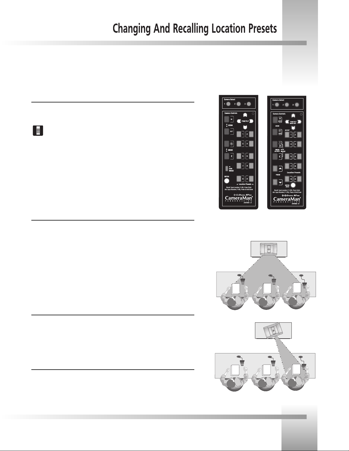
Using the Camera Control Keypad
The Camera Control Keypad included with your Student Camera System comes in a
1-CCD or 3-CCD version.
For information on the specific features of your systems Keypad Controller, refer to
the included Keypad operations manual.
Both versions of the Keypad include the following control features:
Camera Select Buttons Used to select which camera the keypad will control.
Zoom IN and OUT Used to tighten and widen the on-screen image.
Pan/Tilt Arrows Used to move the camera left and right, up and down.
IMAGE controls Used to manually brighten (sun icon) and darken (moon icon) the
on-screen image.
Location Preset Buttons Used to recall Location Presets 34-71 and 73-99.
Enter Button Used to store and recall Location Presets.
To Set or Change a Student Location
1. Select the camera you want to program using the CAMERA SELECT buttons. (If only
1-CCD Camera
Control Keypad
3-CCD Camera
Control Keypad
using one camera, be sure CAMERA SELECT 1 is pressed.)
2. Use the PAN/TILT arrows to move the camera to the desired location.
3. Only when desired, use the manual ZOOM buttons to set the needed Zoom
perspective.
4. Only when desired, use the manual IMAGE buttons to set the needed light/dark
The camera can be set
to show a wide-angle
group view, or...
contrast.
5. Input the Location Preset number (133)
6. Then press and hold the ENTER button until you hear two beeps. The two beeps
indicate the Location Preset has been stored.
To Set the Wide-angle Group View
1. Follow steps 1-4 listed above to achieve a wide-angle view.
2. Input Location Preset Number 72 to be the default preset.
3. The press and hold the ENTER button until you hear two beeps. The two beeps
indicate the GROUP View has been stored.
...focus on a location
preset when a press-totalk microphone button
is pressed.
To Recall a Student Location
When a student wishes to speak, the student simply presses the locator button on the
microphone and the CameraMan Camera will pan, tilt and zoom in on that student,
magnifying his or her image. When the student is done speaking, the CameraMan Camera will
return to a wide-angle shot of the classroom (preset 72).
Page 9
Page 13
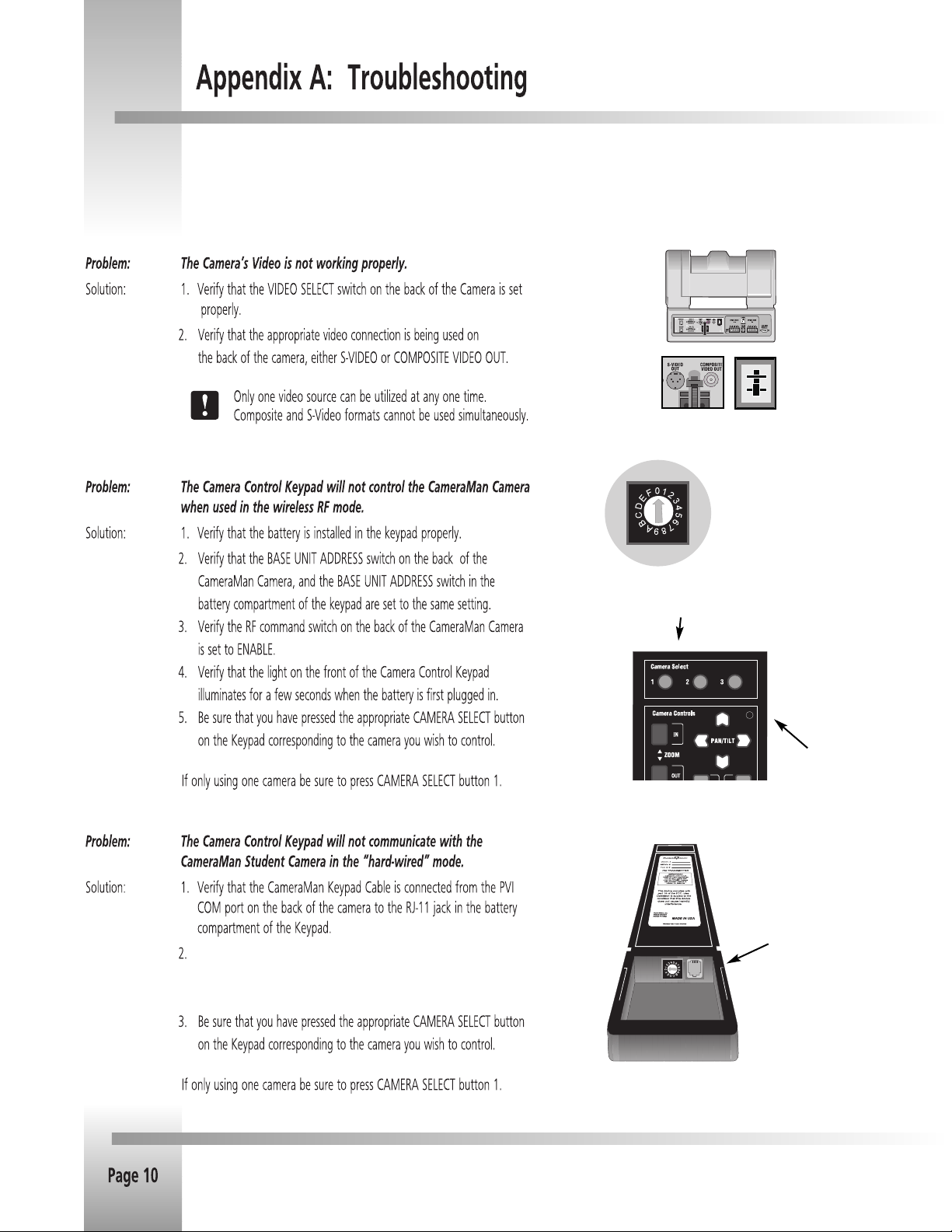
Should you have any problems with your CameraMan Student Camera System, please refer to the following guide. After referring
to the guide, should you have any questions or problems, please contact your authorized reseller or Grass Valley at (904) 596-3500.
Video Select
Switch
Camera Select Buttons
Video
connection
jacks
Base Unit Address
Rotary Switch on
CameraMan, Keypad
and press-to-talk
microphones
Communication
Light
Does the light on the front of the keypad come on for a few seconds
when the keypad is first p;ugged in ? If not, replace cable with a
Grass Valley supplied cable only.
RJ-11 Jack
Page 14

Problem: When a student microphone is activated, the CameraMan
Camera does not move.
Solution: 1. Verify that the PRM POWER switch is ON.
2. Verify the microphone is wired to the correct input on the
PRM and that the corresponding Location Preset is stored.
Press-to-talk
microphone
wired to
audio mixer
and PRM
Recall the location with the Camera Control Keypad.
3. Verify that the BASE UNIT ADDRESS on the back of the
camera is set identically to the BASE UNIT ADDRESS on the
front of the PRM.
4. Verify that no microphones are LOCKED active.
For information on locking and unlocking microphones,
see Low Profile Microphone Manual
5. Verify that the camera is not already at the desired location.
Problem: The camera is locked on one microphone and will not move
when other press-to-talk buttons are pressed.
Solution: Verify that the positive (+) and negative (-) leads on the cable
connecting that microphone to the PRM are lined up correctly
with the contact closure leads on the PRM.
Microphone Inputs on
the back of the PRM
Specifications
KEYPAD RF CONTROL OPTION
RF Range:............................60 ft. from Camera typical
Power:.................................(2) AA Batteries
Dimensions:.........................7.0 L x 2.20 W x 0.85 H
HARD-WIRED KEYPAD OPTION
Range:.................................250 ft. from Camera typical
Power:.................................Supplied through cable
PROGRAMMABLE RESPONSE MODULE
RS-232 Port .........................DB-9 (female) connector
Power Supply: .....................100-240 VAC ; 50-60Hz; 15 VDC output
100 W maximum consumption
Humidity .............................0 to 95% non-condensing
Dimensions:.........................11.75 L x 6.75 W x 3.25 H
PRM Clearance
+
-
+
cables with
negative (-) and
positive (+) leads
-
Page 11
Page 15
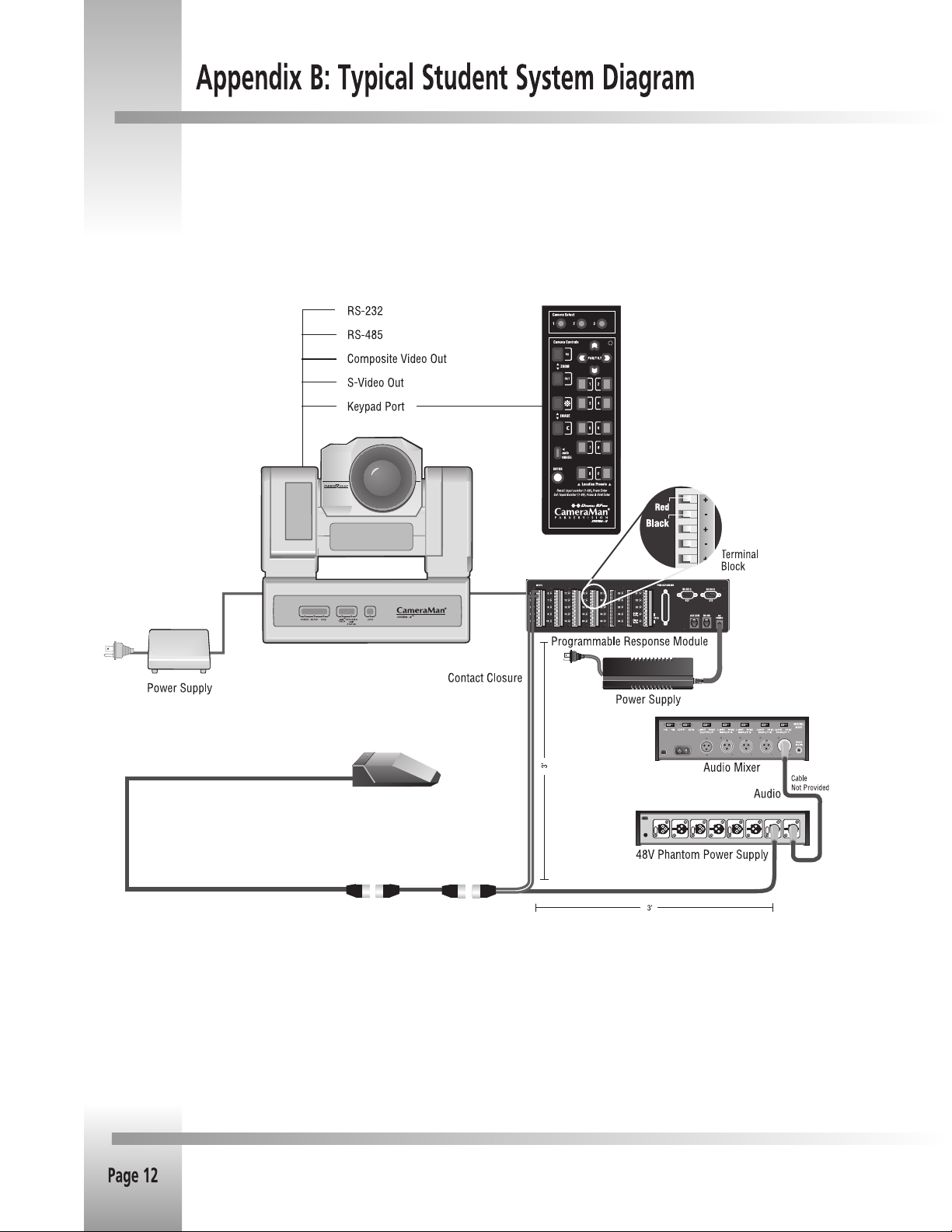
Below is a typical Student Camera System setup. Your specific application needs, however, will determine how you set -up your system.
Page 16

Page 13
Page 17

 Loading...