

Page 1
CameraMan
3e 3-CCD CAMERA
Installation and Operations Manual
071839000
JUNE 2005
Page 2

Contacting Grass Valley
Region Voice Fax Address
North America (800) 547-8949
Support: 530-478-4148
Pacific Operations +852-2585-6688
Support: 852-2585-6579
U.K., Asia, Middle East +44 1753 218 777 +44 1753 218 757
France +33 1 45 29 73 00
Germany, Europe +49 6150 104 782 +49 6150 104 223
Copyright © Thomson Broadcast and Media Solutions All rights reserved.
Grass Valley Web Site
The www.thomsongrassvalley.com web site offers the fol-
lowing:
Online User Documentation — Current versions of product cat-
alogs, brochures, data sheets, ordering guides, planning
guides, manuals, and release notes in .pdf format can be
downloaded.
Sales: (530) 478-3347
Support: (530) 478-3181
+852-2802-2996
Grass Valley
P.O. Box 599000
Nevada City, CA
95959-7900 USA
FAQ Database — Solutions to problems and troubleshooting
efforts can be found by searching our Frequently Asked
Questions (FAQ) database.
Software Downloads — Software updates, drivers, and patches
can be downloaded.
Page 3

Table of Contents
List of Figures ix
CameraMan 3e 3-CCD Camera Overview 1
About this Manual 1
3-CCD Product Description 3
Recommended Accessories 4
3-CCD Camera Components 6
CameraMan Ports and Jacks 8
CameraMan LED Displays 9
CameraMan Configuration Switches 10
Connecting the CameraMan 3e 3CCD Camera 13
Mounting the CameraMan 3e 3-CCD Camera
13
Connecting to the Camera System 15
Connecting Camera Control Devices 17
071839000
June 2005 viii
Page 4

Cable Restraint and System Power 19
Configuring the CameraMan 3e 3CCD Camera 21
Switch Configuration 21
Using the CameraMan 3e 3-CCD
Camera 25
System Startup 25
Installing and Using the 3e Application 27
CameraMan 3e 3-CCD PC Application 27
Appendix A 31
CCU Default Settings 31
Appendix B 35
Multi-Camera Applications 35
Appendix C 37
Camera Specifications 37
Appendix D 39
Pin-Out Diagrams 39
Appendix E 41
Field-Of-View Specifications 41
Appendix F 43
Typical System Diagrams 43
Appendix G 45
Troubleshooting 45
ix CameraMan 3e 3-CCD Camera Installation and Operations Manual
Page 5

Appendix H 47
Warranty Information 47
Index 49
CameraMan 3e 3-CCD Camera Installation and Operations Manual x
Page 6

xi CameraMan 3e 3-CCD Camera Installation and Operations Manual
Page 7

List of Figures
3-CCD Camera Control Keypads 4
SHOT Director 4
SCRIPT Viewer Display 5
Front and Rear View of Camera 6
Mini Docking Station 6
Power Supply 7
Front and Back of T-Connector 7
Ports and Jacks 8
Configuration Panel 10
Camera Clearance Diagram 13
Bottom of Camera 14
Back of Camera with Video Outs 15
Back of Camera with RS-232 Port 16
Battery Compartment of Keypad 17
Back of SHOT Director 18
Back of Camera with Power 20
Configuration Plate 21
Back of Camera with Power 25
Camera Network 36
Distance’s Impact on FOV 41
Zoom’s Impact on FOV 42
Typical System Setup 43
071839000
June 2005 ix
Page 8

List of Figures
x CameraMan 3e 3-CCD Camera Installation and Operations Manual
Page 9

Chapter 1
CameraMan 3e 3-CCD
Camera Overview
About this Manual
The CameraMan 3e 3-CCD Camera is unmatched
in quality, flexibility and expandability, providing one
of the best video-communications cameras in the
industry.
This manual will introduce the CameraMan 3e 3CCD Camera, explain how to install, connect and
configure it, and how to use it in single and multicamera network applications. In addition, useful diagrams and charts can be found in the appendices,
providing technical specifications.
Two icons are used throughout this manual:
This icon alerts important instructions in the operation and maintenance of the CameraMan 3e 3CCD Camera.
This icon alerts tips or noteworthy suggestions in
the operation or maintenance of the CameraMan 3e
3-CCD Camera.
071839000
June 2005 1
Page 10

Chapter 1
The terms Visibly Better, System II, IMAGE, WhisperDRIVE Plus and General Pan/Tilt Camera System are registered trademarks of Grass Valley, Inc.
in the United States of America. The terms CameraMan and Grass Valley are registered logos in the
United States of America. Any commercial use of
these registered trademarks and logos is prohibited
by federal law.
The manufacturer reserves the right to change
specifications and warranty at any time without
notice or obligation.
Refer all Warranty and Servicing to the Grass Valley
Consumer Center listed in the back of this manual.
No part of this manual may be copied or reproduced
without express written consent of Grass Valley, Inc.
2000 Grass Valley, Inc.
DURACELL is a registered trademark of Duracell,
Inc.
The 3e 3-CCD Camera should include these
components:
• One CameraMan 3e 3-CCD Camera with Mini
Docking Station attached (when applicable)
• One CameraMan Power Supply
• One RS-485 Connector “T”
• One 3’ CameraMan Communication Cable
• One 25’ CameraMan Keypad Cable
• One 3-CCD Installation and Operations Manual
The 3e 3-CCD Camera models addressed in this
manual include:
• CPT-3012-A3DS
• CSC-3012-A3DS
• CPC-3012-A3DS
2 Ca meraMan 3e 3-CCD Camera Ins talla tion a nd Operations Manual
Page 11

CameraMan 3e 3-CCD Camera Overview
3-CCD Product Description
Product Description The 3-CCD Camera’s pan/tilt functions, zoom per-
The CameraMan 3e 3-CCD is compatible with the
SHOT Director JSC-2200 only.
The 3-CCD Camera is designed to be used in a variety of applications. This camera may have been purchased with one of the below packages. Information
on upgrade paths, and recommended accessories
can be found in this section.
spective, focus and IMAGE settings can be controlled via Grass Valley’s Remote Control Keypad,
SHOT Director, or Tracking Keypad. In addition to
the camera-control the optional accessories provide, they also provide multi-camera control and
store up to 125 presets per camera.
Student Camera Upgrade Package
Presenter Camera Upgrade Package
Used in distance learning applications, this system
gives each student the power to be instantly identified by the camera with the touch of a press to talk
microphone (such as Grass Valley’s Low Profile
Microphones). This includes the Programmable
Response Module for distributed preset control and
a 3-CCD Camera Control Keypad.
Used in distance learning, telemedicine and videoconferencing applications. The system gives presenters and instructors the ability to provide
dynamic presentations while the camera automatically follows their every move. Includes a Tracking
Ring Package, 3-CCD RF Tracking Keypad, and
Main Docking Station.
CameraMan 3e 3-CCD Camera Installation and Operations Manual 3
Page 12
Recommended Accessories
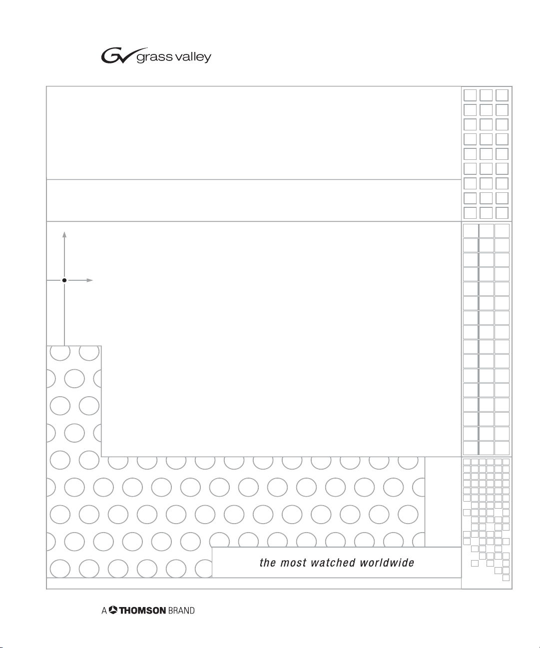
Camera Control Keypad
FIGURE 1.1 3-CCD Camera Control Keypads
Whether used in wireless RF, or hard-wired mode,
this keypad gives the ability to control the pan, tilt,
zoom, focus, iris, and location presets for up to three
separate cameras. The standard keypad comes
standard with the Student Camera System, and the
Tracking Keypad comes standard with the Presenter
Camera Systems.
Chapter 1
SHOT Director
FIGURE 1.2 SHOT Director
Some applications require precise and flexible camera control. Grass Valley’s SHOT Director is a joystick controller designed to give ultimate control by
affording the ability to adjust to the pan, tilt, zoom,
focus, iris, CCU functions and location presets on 1
to 16 different cameras from one location. And its
built-in CCU functionality allows adjustment of each
camera’s on-screen image.
4 Ca meraMan 3e 3-CCD Camera Ins talla tion a nd Operations Manual
Page 13
CameraMan 3e 3-CCD Camera Overview
CameraMan Tally Light
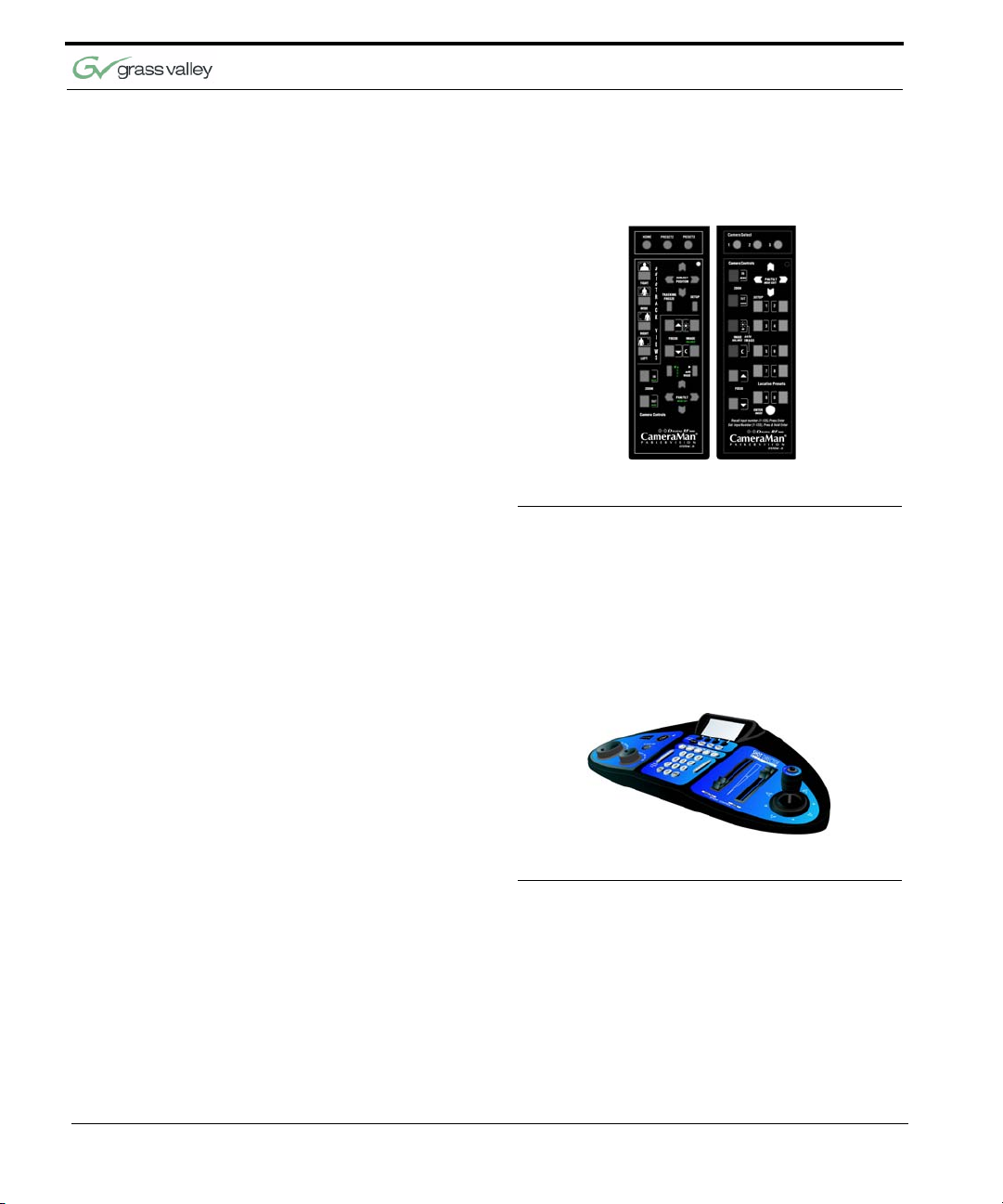
SCRIPT Viewer Display
For visual indication of which camera is selected in
a multi-camera application, the CameraMan Tally
Light provides a high intensity indication from an
easy-to-install interface on the rear of the camera. A
bright red indicator is mounted to the top of a flexible
pedestal, allowing precise adjustment and positioning of the light for the best possible studio-wide
observation. Control of the Tally Light can be
accomplished through Control Center, and STUDIO,
as well as via an external closure connected to a
side-mounted Phoenix connector. All current 3-CCD
cameras are Tally Light compatible, and previous
models are factory upgradeable.
FIGURE 1.3 SCRIPT Viewer Display
Adding a full-feature teleprompting display that
moves with the camera is now available with the
addition of Grass Valley’s powerful SCRIP Viewer
system. The 15” active matrix, full color displays are
available separately and are easily mounted to the
camera. Contact your reseller for more information
on the complete Script Viewer system.
CameraMan 3e 3-CCD Camera Installation and Operations Manual 5
Page 14
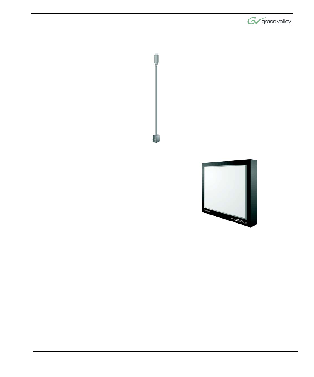
3-CCD Camera Components
This section includes a description of each part that
came with the CameraMan 3e 3-CCD Camera.
CameraMan 3e 3-CCD Camera
FIGURE 1.4 Front and Rear View of Camera
The camera and its integrated intelligent pan/tilt system is the primary component, and the basis for all
of Grass Valley’s CameraMan camera systems.
Mini Docking Station
Chapter 1
FIGURE 1.5 Mini Docking Station
The Mini Docking Station should be attached to the
back of the camera. This box is the point of connection for all RS-232 and RS-485. The only time this
box needs to be removed is if the camera is
upgraded to a Presenter Camera System.
Note: If a Presenter System was purchased, the
Mini Docking Station is not needed.
6 Ca meraMan 3e 3-CCD Camera Ins talla tion a nd Operations Manual
Page 15
CameraMan 3e 3-CCD Camera Overview
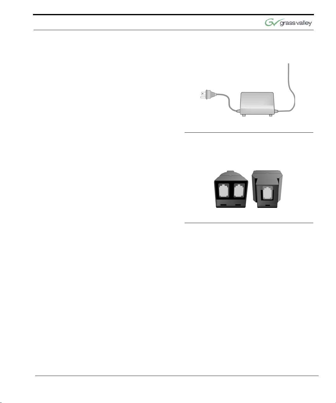
CameraMan Power Supply
Connection Accessories
FIGURE 1.6 Power Supply
The included power supply enables use with 50/60
Hz, 100-240V Power sources.
FIGURE 1.7 Front and Back of T-Connector
• RS-485 Connector “T”
• 3’ CameraMan Communication Cable
• 25’ CameraMan Keypad Cable
CameraMan 3e 3-CCD Camera Installation and Operations Manual 7
Page 16
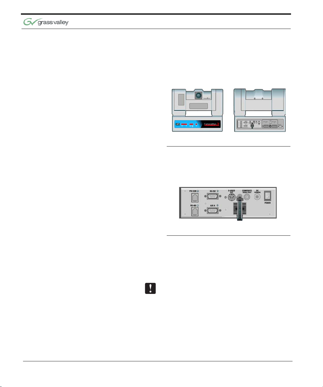
CameraMan Ports and Jacks
The back of the CameraMan 3e 3-CCD Camera has
a variety of ports and jacks used to connect the
camera to other video and camera control components in a system.
FIGURE 1.8 Ports and Jacks
VIDEO OUT This is a Composite Video Out signal on the left
and an SDI Video Out signal on the right.
PVI COM Jack Used by certain Grass Valley devices as a
communication interface to the camera system.
(For example, a hard-wired keypad would attach
here). This is a standard 6-conductor RJ-11 jack.
RS-485 Jack Used for RS-485 communications between the
camera system and other Grass Valley devices.
This jack can be used to network multiple cameras
or to connect appropriate Grass Valley approved
peripherals using a Grass Valley T-connector. This
is a standard 4-position modular handset jack.
Auxiliary
Communication Port
RS-232 Port Provides RS-232 communications to external
S-Video Jack Y/C
Provides communications to select Grass Valley
peripherals and provides capability for future
expansion.
devices such as PC’s or other vendor control
systems. This connector is a standard DB-9
(female).
Chapter 1
Cable Restrainer Helps keep cables from becoming disconnected,
or hindering the pan and tilt capabilities.
Composite Video Jack Y/Pr/Pb
8 Ca meraMan 3e 3-CCD Camera Ins talla tion a nd Operations Manual
Page 17

CameraMan 3e 3-CCD Camera Overview
DC Power Jack Power input for the CameraMan Camera. Plug
CameraMan LED Displays
only a Grass Valley power supply (supplied) into
this jack. No other types of power supplies should
be used.
Power Used to power on/off the CameraMan Camera.
The SHOT Director can communicate with the cameras through either the RS-485 or RS-232 port.
On the front of the CameraMan 3e 3-CCD Camera,
there are several LEDs. These indicate various
functions that are being performed by the camera.
Below is a description of each.
When the camera is first powered ON, all LEDs will
illuminate. During this time, basic system hardware
checks are being performed. These checks include
communication with the camera interface board
which verifies proper installation of the camera block
on the pan/tilt unit. After the initial system checks
are completed, the LEDs will turn on and off one by
one in a binary pattern. This pattern represents the
progress the camera is making during hardware initialization. During this initialization, pan/tilt positions
and camera settings are being restored. Once initialization is complete, the camera LEDs will represent the following functions:
Power Indicates that the camera has an active power
supply and is powered ON.
Setup The camera is in the camera setup mode.
COM Indicates that the camera is receiving valid
network data on a communication link (the LEDs
on the back of the camera only indicate line
activity, not valid data).
CameraMan 3e 3-CCD Camera Installation and Operations Manual 9
Page 18
AutoTRACK Indicates that the camera is in autoTRACK mode.
The IR spinners are running and the camera is
attempting to acquire data from the TRP.
Tracking Unit Status Indicates that the camera has acquired the RF
signal from the TRP and is receiving valid data.
When this LED is OFF, TRP power is usually OFF.
Lock Non-functional.
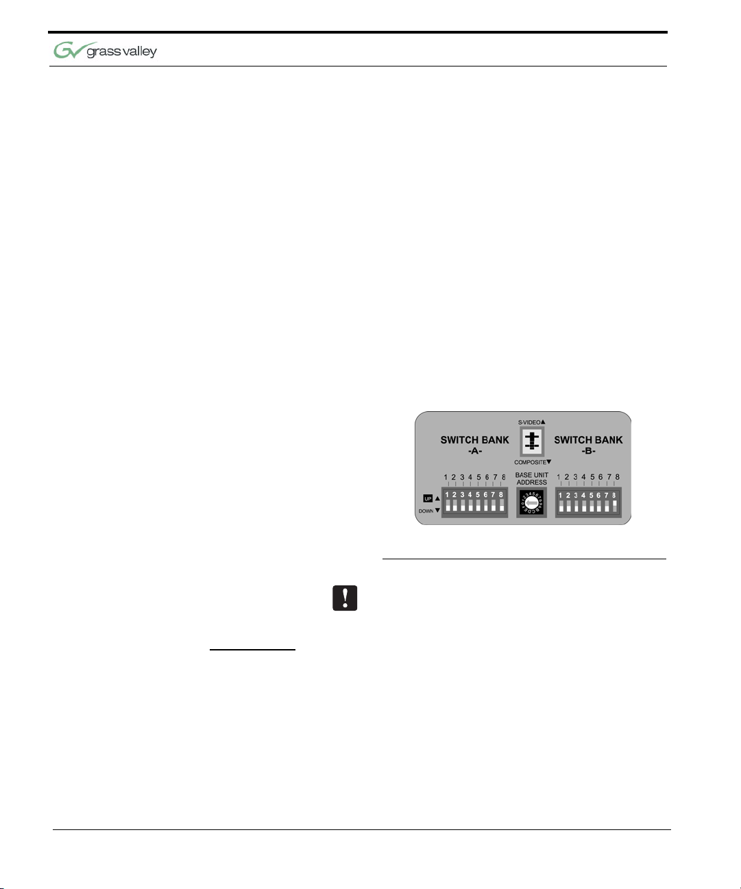
CameraMan Configuration Switches
Behind the configuration plate on the lower right
side rear of the 3-CCD Camera is the configuration
panel. These DIP and rotary switches are used to
link the camera’s settings to other components in
the system.
Chapter 1
FIGURE 1.9 Configuration Panel
Note: After changing any switch’s settings, turn the
camera off, then back on to activate the change.
Refer to page 21 for Dip Switch configuration.
Switch Bank A
Switch 7
(Baud Rate Switch)
Switch 8
(Memory Lock Select
Switch)
Switches 1, 2, 3, 4, 5, 6 Reserved for future use.
10 Ca meraMan 3e 3-CC D Ca mer a Instal lat ion and Operations Manual
Used to change the camera’s Baud Rate
Can be used to prevent programmed settings from
being accidentally overridden.
Page 19

CameraMan 3e 3-CCD Camera Overview
Center Control Switches
Video Select Switch Used to set the video source to Composite (down)
Base Unit Address Used to configure the address of the Camera.
Switch Bank B
or S-Video (up). Cannot be used simultaneously.
Switch 1
(Protocol Select Switch)
Switch 4
(RF Commands Switch)
Switch 5
(Preset Save)
Switch 8
(Interlink Switch
Switches 2, 3, 6, 7 Reserved for future use.
Used to select the type of Protocol being used for
RS-232 and RS-485 communications. This can be
configured as either Basic or High Reliability.
Used to enable or disable the RF Receiver in the
CameraMan camera.
Used to determine how the preset settings will be
saved.
Used to disable commands from being sent on the
RS-485 bus to other CameraMan devices.
Tally Light Interface Port
Provides output and external control for CameraMan Tally Light.
CameraMan 3e 3-CCD Camera Installation and Operations Manual 11
Page 20

This page was intentionally left blank.
Chapter 1
12 Ca meraMan 3e 3-CC D Ca mer a Instal lat ion and Operations Manual
Page 21

Chapter 2
Connecting the CameraMan
3e 3-CCD Camera
Mounting the CameraMan 3e 3-CCD Camera
Mount the Camera on any flat, non-slick, non-metal
surface with a minimum supporting area of 8” x 8” by
following these easy steps.
Step 1 Check the selected camera-location to ensure that
there is enough camera and cable clearance space
for the CameraMan to pan and tilt without obstruction (see Figure 2.1).
FIGURE 2.1 Camera Clearance Diagram
Note: Do not mount the camera upside down, or
with more than a 10o angle from horizontal.
071839000
June 2005 13
Page 22

Chapter 2
Tip: See Appendix E: FIELD OF VIEW SPECIFICATIONS on page 41, to assist in placing the CameraMan to achieve optimum optical views.
Step 2 Locate the zero-degree position mark labeled
FRONT on the bottom of the base unit. This mark
helps ensure that the base unit is calibrated correctly. Point this indicator mark in the direction that
best reflects the center of travel in which the camera
will be used (usually the center of the room).
FIGURE 2.2 Bottom of Camera
Step 3 To ensure that the camera-mounting is not prone to
vibrations, securely fasten the camera to a rigid flat
surface using a 1/4”-20 UNC cap screw that does
not extend into the base platform by more than 0.4”.
(The screw hole is provided in the base platform for
this purpose. The cap screw is not provided.) This
screw should be hand-tightened. If necessary, use a
hardening threadlock to prevent the screw from
loosening.
Note: Be sure to take environmental conditions into
consideration when operating the camera. Always
operate the camera indoors, and follow the temperature and humidity specifications outlined in Appendix C: CAMERA SPECIFICATIONS on page 37.
14 Ca meraMan 3e 3-CC D Ca mer a Instal lat ion and Operations Manual
Page 23

Connecting the CameraMan 3e 3-CCD Camera
Connecting to the Camera System
Connecting to Video Outputs on Mini Docking Station
Follow the instructions found in this section to begin
connecting the camera to the system.
Tip: After connecting each cable to the camera, let it
hang loosely behind the camera. Then follow the
instructions about restraining the cables on page 19
before attaching the other ends of the cable to other
equipment. This will relieve undue stress on the
cables, allowing the camera to move freely.
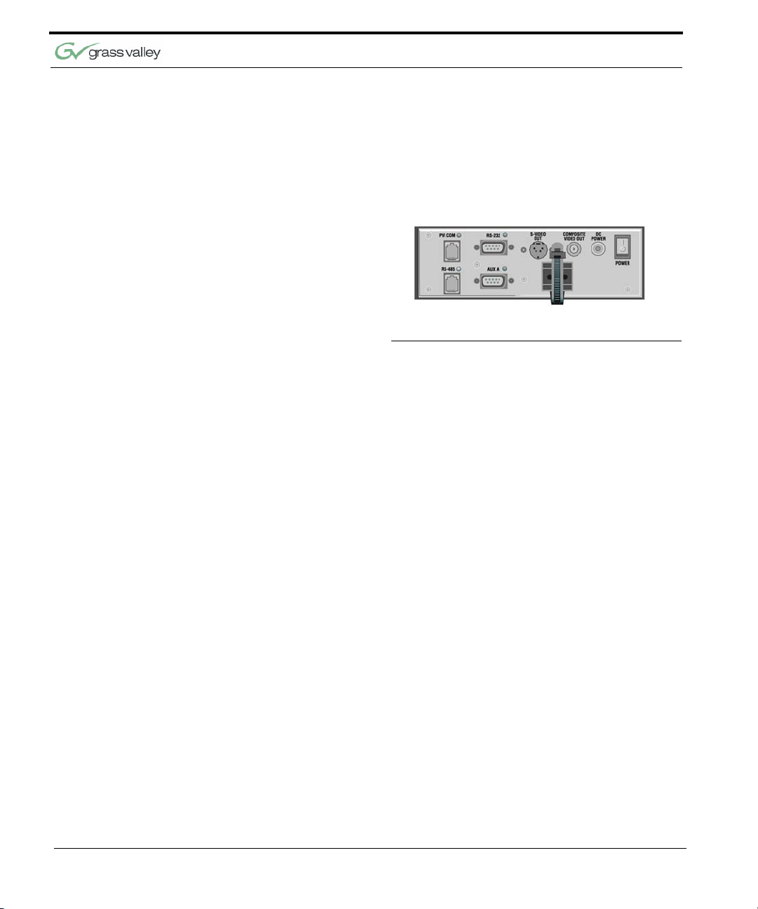
FIGURE 2.3 Back of Camera with Video Outs
CameraMan supports both composite and S-VIDEO
formats, although you can use only one at a time.
For composite format, connect to the BNC jack on
the Connector Box on the back of the camera,
labeled COMPOSITE VIDEO OUT, using a standard
coaxial cable with a BNC connector (not provided).
Verify that the Video Select switch is set to COM-
POSITE. The switch is located behind the switch
plate on the back right of the camera.
For S-VIDEO format, connect to the S-VIDEO jack
on the back of the camera using a standard SVIDEO cable (not provided). Verify that the Video
Select switch is set to S-VIDEO. The switch is
located behind the switch plate on the back right
CameraMan 3e 3-CCD Camera Installation and Operations Manual 15
Page 24

Connecting to the RS-232 Port
Chapter 2
of the camera. For video output specifications, refer
to Appendix C: CAMERA SPECIFICATIONS on
page 37.
FIGURE 2.4 Back of Camera with RS-232 Port
The 3e 3-CCD Camera provides for RS-232 communications using the DB-9 jack on the back of the
camera, labeled RS-232. This RS-232 port can be
used to control the CameraMan Camera from external devices such as a PC or other vendor control
system (i.e.: AMX, Crestron). Connect to this port
using a standard computer cable with a DB-9 connector. When used with a SHOT Director, this port
operates at 19,200 Baud, No Parity and software
hand-shaking using Grass Valley High Reliability
protocol. Otherwise, the port operates at 9600
Baud, No Parity, and software hand-shaking using
Grass Valley High Reliability or Basic protocols.
Note: To verify which protocol is being used, check
the PROTOCOL switch on the configuration panel
on the back lower-right of the Camera.
Tip: The COM light above the RS-232 port is used
to indicate communication activity.
Tip: For the DB-9 pinout port information, see the
Appendix D: PIN-OUT DIAGRAMS, page 39.
16 Ca meraMan 3e 3-CC D Ca mer a Instal lat ion and Operations Manual
Page 25

Connecting the CameraMan 3e 3-CCD Camera
Connecting Optional Camera Control Devices
Connecting Camera Control Devices
Camera Control Keypad The optional Camera Control Keypad controls the
CCU functionality is only accessable via SHOT
Director, AMX, Crestron, or the CameraMan 3e PCbased CCU application.
There are several ways to control the CameraMan’s
movement. The following information explains how
to connect and configure the optional Camera Control Keypad, or the SHOT Director.
Note: Do not use the Camera Control Keypad and
the CameraMan SHOT Director at the same time.
camera’s movement via wireless RF technology (up
to 60 feet), or hard-wired connection (up to 250
feet). If you choose to use a Camera Control Keypad in the hard-wired mode, follow these directions
for installation.
1. Using the 25’ CameraMan Keypad Cable
included with your camera, connect one end of
the cable to the RJ-11 type jack located in the
battery compartment of the keypad.
FIGURE 2.5 Battery Compartment of Keypad
2. Connect the other end of the cable to the RJ-11
type jack on the back of the camera, labeled PVI
COM.
CameraMan 3e 3-CCD Camera Installation and Operations Manual 17
Page 26

Chapter 2
Tip: When the system is powered on, the light on
the keypad should illuminate momentarily, indicating
the keypad is ready for operation. The light located
above the PVI COM port is used to indicate communication activity.
Note: Using cable other than Grass Valley supplied
cable for the PVI COM port may cause damage.
SHOT Director The optional SHOT Director multi-camera controller
can be connected in hard-wired mode only. Follow
these directions to connect the SHOT Director to the
CameraMan.
1. Using a standard RS-485 cable, connect one
end of the cable to one of the RS-485 jacks
(either one) on the back of the SHOT Director.
FIGURE 2.6 Back of SHOT Director
2. Connect the other end of the cable to:
• The jack labeled RS-485 on the back of the
CameraMan connector box for single camera
applications, or
• The T-Connector for multiple-camera applica-
tions. Then use the provided 3’ CameraMan
Communication Cable to connect the T-connector to teh camera’s RS-485 jack.
Note: If using a Camera Control Keypad or SHOT
Director, refer to its operations manual. If it is
unavailable, contact your local reseller, or Grass
Val ley.
To use the RS-232 port for communication between
the camera and SHOT Director, connect one end of
the cable to the RS-232 port on the CameraMan
Connector Box (Mini Docking Station), and connect
the other end of the RS-232 cable to the COM 1
Port on the SHOT Director.
18 Ca meraMan 3e 3-CC D Ca mer a Instal lat ion and Operations Manual
Page 27

Connecting the CameraMan 3e 3-CCD Camera
Cable Restraint and System Power
Notice that if left alone, the connected cables may
impede the camera’s movement. To combat this, the
3e 3-CCD Camera comes equipped with two cable
restrainers on the left back, and on the Mini Docking
Station. Follow these instructions to properly restrain
the cables and power-up the camera.
1. Locate the cable restraint on the back left side of
the camera.
2. Insert cable(s) through the cable restraint from
left to right.
Note: Allow 16” of cable between the restraint and
the connection port to provide enough slack for the
camera’s tilting movement.
3. Tighten the restraint by pulling on the strap’s
“free” end to prevent any cable from becoming
dislodged. (The cable restraint is reusable and
adjustable).
4. Group the cables with all the other cables con-
nected to the connector box and follow the
instructions below to feed them through the
lower cable restraint.
For lower cable connections
1. Insert all cables (upper and lower) through the
cable restraint from left to right. This will result in
the cables being located approximately in the
center of the camera, instead of near the edge.
2. Tighten the restraint by pulling on the strap’s
“free” end to prevent any cable from becoming
dislodged.
Note: To relieve undue stress on the camera and
the cable connections, it is important to fasten all
cables using the cable restrainer on the back of the
camera.
Note: Be sure to leave enough slack in the cables
for the camera to pan left and right free of any constraints.
CameraMan 3e 3-CCD Camera Installation and Operations Manual 19
Page 28

Connecting the Power Supply
Chapter 2
FIGURE 2.7 Back of Camera with Power
Mount the Power Supply with any orientation, or on
top of a table or roll-about unit by using the following
steps.
1. Verify that the POWER switch, on the back of the
camera, is turned OFF.
2. Plug the 5.5mm female connector from the
power supply cord into the DC POWER jack in
the back of the camera.
3. Connect the other end of the power supply into a
120 VAC source.
Powering On 1. Simply switch the Power button on the back of
the CameraMan Camera.
20 Ca meraMan 3e 3-CC D Ca mer a Instal lat ion and Operations Manual
Page 29

Chapter 3
Configuring the CameraMan
3e 3-CCD Camera
Switch Configuration
Now that CameraMan is connected to the power
supply and control devices, the Camera must be
configured to work in the desired application. To
begin, remove the configuration plate on the back
right side of the camera by removing the two screws
holding it in place. Behind it are the configuration
switches.
FIGURE 3.1 Configuration Plate
071839000
June 2005 21
Page 30

Switch Bank A
Chapter 3
Dip Switch 7
(Baud Rate)
Dip Switch 8
(Memory)
This switch is used to configure the camera’s
Baud Rate for the RS-232 and RS-485 ports.
Switch UP for 19,200 and DOWN for 9600.
(factory default: UP)
For the majority of applications, this switch should
be set to UNLOCK (UP). When DOWN, all
programmed features are locked and cannot be
overridden. (factory default: UP)
Central Control Switches
Base Unit Address Use the 16-position rotary switch labeled BASE
UNIT ADDRESS to set the unique identification
number for this CameraMan. If using the optional
Keypad, SHOT Director, or another control
system, refer to the documentation provided with
those accessories for proper configuration.
For setting up a camera network, see page 35,
Appendix B: MULTIPLE CAMERA APPLICATIONS.
Switch Bank B
Dip Switch 1
(Protocol)
Dip Switch 4
(RF Command)
Select the communication protocol which will be
used by the RS-232 and RS-485 ports on the
camera. The High Reliability protocol includes
some advanced error checking that is not
performed in the Basic protocol. (factory default:
DOWN)
When this switch is DOWN, the camera responds
to commands sent from an RF Keypad. When it is
UP, the RF receiver in the camera is disabled and
the camera cannot receive commands directly
from a wireless keypad. (factory default: DOWN)
When using multiple cameras networked on the RS485 bus, only one camera should have its RF
receiver enabled. Set switch 4 on the other cameras
to UP.
22 Ca meraMan 3e 3-CC D Ca mer a Instal lat ion and Operations Manual
Page 31

Configuring the CameraMan 3e 3-CCD Camera
Dip Switch 5
(Preset Save)
Dip Switch 8
(Interlink)
Use this switch to determine how the preset
settings will be recalled. DOWN recalls your
Manual Gain, Iris, and Focus settings. UP recalls
only the Auto settings for presets and autoTRACK
Views. (factory default: DOWN)
Use this feature in multi-camera applications.
When it is DOWN, all commands will be passed
onto the RS-485 communication bust to the
appropriate camera. For a single-camera
application, the setting of this switch does not
matter. (factory default: DOWN)
All switches not discussed in this section should
remain in the DOWN or OFF position.
CameraMan 3e 3-CCD Camera Installation and Operations Manual 23
Page 32

This page was intentionally left blank.
Chapter 3
24 Ca meraMan 3e 3-CC D Ca mer a Instal lat ion and Operations Manual
Page 33

Chapter 4
Using the CameraMan
3e 3-CCD Camera
System Startup
Once all necessary connections and configurations
are made, you are ready to turn on the system.
1. Just switch the Power button on the back of the
CameraMan Camera to the ON position. The
Camera should automatically enter its position
calibration mode and then stop at the zero
degree point.
FIGURE 3.1 Back of Camera with Power
071839000
June 2005 25
Page 34

Chapter 4
2. Verify that the camera is now facing in the direc-
tion the “FRONT” label was pointing during
mounting (see page 14).
3. If you are using the optional Camera Control
Keypad or SHOT Director, make sure its base
unit address is the same as on the camera. If
they are, verify that the camera’s PAN and TILT
functions are working properly.
Cameras 1-16 on SHOT Director correspond to
Base Unit Adresses 0-F respectively: 1=0, 2=1,
3=2... 11=A, etc.
Tip: If the camera does not move, refer to the
TROUBLESHOOTING section of the Camera Control Keypad, or SHOT Director manual.
26 Ca meraMan 3e 3-CC D Ca mer a Instal lat ion and Operations Manual
Page 35

Chapter 5
Installing and Using
the 3e Application
CameraMan 3e 3-CCD PC Application
The next few pages discuss the installation of the
CameraMan 3e Application. CCU functions can be
accessed and manipulated through use of this application.
Hardware and OS Requirements
071839000
June 2005 27
To install and run CameraMan 3e application, your
system must be running one of the following operating systems:
• Windows 95
• Windows 98
• Windows NT
• Windows ME
• Windows 2000
• Windows XP
The PC on which you install CameraMan 3e Application should have the following hardware:
• A Pentium or later microprocessor
Page 36

Chapter 5
• 32 MB of RAM
• At least one free COM port for communication
with the target system
• A CD-ROM drive (for software installation)
Installing the CameraMan 3e Application
Connecting the Camera to the PC
Starting the CameraMan 3e Application
If you have not installed CameraMan 3e application,
do so now by inserting the CameraMan 3e CD in
your PC’s CD-ROM drive. If autorun is enabled, the
CD installation will begin automatically.
If autorun is diabled or the installation otherwise
does not start, use the Windows Start / Run menu
or Windows Disk Explorer to launch setup.exe from
the root folder of the CD-ROM.
The installation program will guide you through the
installation process. Most steps of the process are
self-explanatory and not covered in this section.
The PC can be connected directly to any CameraMan 3e Pan/Tilt in the NETWORK or to a Digital
SHOT Director through a 9-D straight-thru cable.
In order to address every camera, the user needs to
change the camera number under the settings
menu.
1. Use the Windows Start / Programs and find the
application shortcut to start the CameraMan 3e
Application. Double-click the shortcut.
2. Once the application is initiated and connected
to the camera network, the LOAD button will
flash to indicate that the current CCU camera
settings are ready for download. Click on the
LOAD button to begin download. During the
download process, a progress bar will appear
underneath the LOAD button.
Once the LOAD process is complete, the user can
modify any settings available and save those settings as a “power-on default” by clicking on SAVE +
OK. To verify that the settings were properly saved,
cycle power the CameraMan 3e unit and proceed to
download the camera CCU settings. A confirmation
28 Ca meraMan 3e 3-CC D Ca mer a Instal lat ion and Operations Manual
Page 37

Installing and Using the 3e Application
screen will appear prior to overwriting the factory
defaults.
By default, this application will be set for COM1 and
CAM-1. If you are using another port, click on SET-
TINGS to select the correct COM port. The camera
number can also be selected here.
CameraMan 3e 3-CCD Camera Installation and Operations Manual 29
Page 38

This page was intentionally left blank.
Chapter 5
30 Ca meraMan 3e 3-CC D Ca mer a Instal lat ion and Operations Manual
Page 39

APPENDIX A
CCU Default Settings The following is a list of the factory default CCU set-
tings. These can only be accessed through the
SHOT Director, the CameraMan 3e PC-based Application, or a third party device that supports the CameraMan 3e 3-CCD. AMX and Crestron are two such
devices.
Exposure
Function Set to
Shutter Speed Auto (unknown)
Exposure Mode Auto
Gain Auto (unknown)
Miscellaneous
Function Set to
Display Off
Aspect Ratio 4:3
Picture Effect Off
Pain Controls
Function Set to
AWC Mode Auto
Red Gain Auto (unknown)
Blue Gain Auto (unknown)
CameraMan 3e 3-CCD Camera Installation and Operations Manual 31
Page 40

Lens Controls
Function Set to
Auto Focus On
Focus Position Auto (unknown)
Auto Iris On
Iris Position Auto (unknown)
Digital Zoom On
Zoom Position 0
Shutter Speed
(Shutter mode must be set to Manual)
0 = 1/4 7 = 1/125 14 = 1/1500
1 = 1/8 8 = 1/250 15 = 1/2000
2 = 1/15 9 = 1/250 16 = 1/3000
3 = 1/30 10 = 1/350 17 = 1/4000
4 = 1/60 11 = 1/500 18 = 1/6000
Appendix A
5 = 1/90 12 = 1/725 18 = 1/10000
6 = 1/100 13 = 1/1000
White Balance Mode
0 = Full Auto
1 = Indoor
2 = Outdoor
3 = OnePushWB
4 = Manual
32 CameraMan 3e 3-CCD Camera Installation and Operations Manual
Page 41

CCU Default Settings
Gain
(White Balance Mode must be set to Manual)
0 = -3 db
1 = 0 db
3 = 3 db
4 = 6 db
5 = 9 db
6 = 12 db
7 = 18 db
One Push AWC
(White Balance Mode must be set to OnePushWB)
0 = or any # < 256
Red Gain
(White Balance Mode must be in Manual)
0 ~ 255 = Red Gain
Blue Gain
(White Balance Mode must be set to Manual)
0 ~ 255 = Blue Gain
Shutter Mode
0 = Auto
1 = Manual
Digital Zoom Mode
0 = Optical Zoom
1 = Optical + Digital
CameraMan 3e 3-CCD Camera Installation and Operations Manual 33
Page 42

Focus Mode
Wide Mode
Picture Effect
Display Mode
Appendix A
0 = Manual
1 = Auto
0 = off
1 = 16:9
0 = off
1 = Negative art
2 = Black and White
0 = off
1 = on
34 CameraMan 3e 3-CCD Camera Installation and Operations Manual
Page 43

APPENDIX B
Multi-Camera Applications
If using more than one CameraMan 3e 3-CCD Camera, the cameras need to be set up in a “daisychain” network configuration by following these
steps:
1. Connect the cameras together by plugging the
Grass Valley T-connector into the RS-485 port
on the back of the camera.
2. Connect each camera using a 4-conductor
cable, with 4-position modular handset plugs
wired “straight-through”:
Pin 1... Pin 1
Pin 2... Pin 2
Pin 3... Pin 3
Pin 4... Pin 4
Note: Do NOT use a standard phone cable, as
these are wired differently and may cause damage.
3. Using the BASE UNIT ADDRESS rotary switch,
which is located on the back of the Camera, configure each camera with a unique Base Unit
Address. (i.e.: Camera One would be set with
address 0, Camera Two would be set with
address 1, and so on)
4. In order to control each camera with your Cam-
era Control Keypad, the rotary switch inside the
keypad battery compartment must match the
lowest Base Unit Address in your system. For
example, if the Base Unit Address switches are
set according to the illustration on the next page,
the rotary switch inside the keypad should be set
to zero. The Camera control Keypad can control
up to three cameras.
CameraMan Clearance The minimum dimension for the CameraMan is a
circular diameter of 26”. This accounts for both camera and cable clearance. Check cable movement to
avoid binding and stress on the camera.
Tip: See clearance diagram on page 13.
CameraMan 3e 3-CCD Camera Installation and Operations Manual 35
Page 44

Appendix B
FIGURE B.1 Camera Network
36 CameraMan 3e 3-CCD Camera Installation and Operations Manual
Page 45

APPENDIX C
±
Camera Specifications This device complies with part 15 of the FCC rules.
Operation is subject to the condition that this device
does not cause harmful interference. FCC identifier:
JFECM003-AA.
Mechanical
Mechanical Drives WhisperDRIVE Plus Rated For 5000 Hrs. Of
Continuous Motion
Tilt
o
(Speed: 1o/Sec to 50o/Sec)
25
Pan
Location Presets 125
Location Preset Data Pan, Tilt, Zoom, Focus, Iris
Location Preset
Accuracy
359o (Speed: 1o/Sec to 45o/Sec)
o
±
0.125
Inputs/Outputs
Video Output Composite: 1V[p-p] (75 ohm) BNC
SDI: 270mb/s component (SMPTE 259M) BNC
Y/C: Y: 1.0 Vp-p (sync negative) C: 0.286 Vp-p
RS-232 Port DB-9(F) Connector
RS-485 Port Bus Up To 16 Cameras (4 pos. RJ handset port)
Image Sensor 3CCD 1/4.7-type Interline Transfer, Advanced
HAD CCD
Hor. Resolution 530 TV Lines
Lens 2x zoom, f=3.6mm (wide) to 43.2mm (tele)
Digital Zoom 4x (48x with optical zoom)
Aspect Ratio 4:3/16:9 Switchable
Focal Length F1.6 to F2.8mm
Pixels 960 (H) x 720 (V) (690,000 pixels) in 4:3 mode
1152 (H) x 648 (V) (746,000 pixels) in 16:9 mode.
CameraMan 3e 3-CCD Camera Installation and Operations Manual 37
Page 46

S/N Ratio >50 dB
Angular FOV
Approx. 37.8
Approx. 45.4
Appendix C
o
(wide) 3.3o (tele) (4:3 mode)
o
(wide) 4.0o (tele) (16:9 mode)
Angular FOV w/ 0.5x
Converter
Minimum Working
Approx. 68.0o (wide) 6.5o (tele) (4:3 mode)
o
Approx. 79.8
(wide) 8.0o (tele) (16:9 mode)
100mm (wide end) to 1,000mm (tele end)
Distance
System NTSC Only
Video Output
Analog VBS: 1.0 Vp-p (sync negative)
Y/C: Y: 1.0 Vp-p (sync negative)
C: 0.286 Vp-p (without sync)
R/G/B/Sync: 0.7 Vp-p (sync: 5V TLL level)
Digital Composite: 1V[p-p] (75 ohm) BNC
SDI: 270Mb/s component (SMPTE 259M) via BNC
Sync System Internal
Min. Illumination 15.0 Ix, F1.6
White Balance Auto, Indoor, Outdoor, One-Push, Manual
AE Control Auto, Manual, Iris Priority, Shutter Priority
Focusing System Auto, Manual, One-Push AF, Infinity, Zoom trigger
Electronic Shutter 1/4 to 1/10,000s, twenty (20) steps
Operating Temperature
o
F to 113oF (0o to 45o)
32
CameraMan Clearance The minimum dimension for the CameraMan is a
circular diameter of 26”. This accounts for both camera and cable clearance. Check cable movement to
avoid binding and stress on the camera.
38 CameraMan 3e 3-CCD Camera Installation and Operations Manual
Page 47

APPENDIX D
Pin-Out Diagrams The following pinout connections can be found on
the back of the Mini Docking Station on the rear of
the CameraMan. These diagrams are for reference.
PVI COM RJ-11
Pin Signal
112v
212v
3 Ground
4 Signal A
5 Signal B
6 Ground
RS-485 Four Position
Modular Handset
Pin Signal
1 Ground
2 Signal A
3 Signal B
4 Ground
RS-232 9-Pin Female
D-9 Sub
Pin Signal
2Transmit
3Receive
5 Ground
1,4,6-9 Not Used
5.5mm DC Power Connector
1 + 18v DC
2 Ground
CameraMan 3e 3-CCD Camera Installation and Operations Manual 39
Page 48

This page was intentionally left blank.
Appendix D
40 CameraMan 3e 3-CCD Camera Installation and Operations Manual
Page 49

APPENDIX E
Field-Of-View Specifications
Without Adapter (4:3 mode) Without Adapter (16:9 mode)
Dist. from Lens No Zoom (wide) No Zoom (Wide)
(feet) Hor. (ft) Vert. (ft) Square Feet Hor. (ft) Vert. (ft) Square Feet
10 6.85 5.14 35.17 8.36 4.70 39.32
15 10.27 7.70 79.13 12.54 7.05 88.47
20 13.69 10.27 140.67 16.72 9.41 157.28
25 17.12 12.84 219.80 20.90 11.76 245.75
The following reference charts represent the size of
the field of view and angle of view from various distances and with different lenses in 4:3 and 16:9
modes.
FIGURE E.1 Distance’s Impact on FOV
30 20.54 15.41 316.51 25.08 14.11 353.88
35 23.97 17.98 430.81 29.26 16.46 481.68
40 27.39 20.54 562.69 33.44 18.81 629.13
45 30.81 23.11 712.15 37.63 21.16 796.24
50 34.24 25.68 879.20 41.81 23.51 983.01
55 37.66 28.25 1063.83 45.99 25.87 1189.44
60 41.08 30.82 1266.05 50.17 28.22 1415.54
65 44.51 33.38 1485.85 54.35 30.57 1661.29
70 47.93 35.95 1723.24 58.53 32.92 1926.70
Angle of View
CameraMan 3e 3-CCD Camera Installation and Operations Manual 41
37.80
o
28.81
o
45.38o26.46
o
Page 50

Appendix E
FIGURE E.2 Zoom’s Impact on FOV
With 0.5x Adapter (4:3 mode) With 0.5x Adapter (16:9 mode)
Dist. from Lens No Zoom (wide) No Zoom (wide)
(feet) Hor. (ft) Vert. (ft) Square Feet Hor. (ft) Vert. (ft) Square Feet
10 13.69 10.27 140.67 16.72 9.41 157.28
15 20.54 15.41 316.51 25.08 14.11 353.88
20 27.39 20.54 562.69 33.44 18.81 629.13
25 34.24 25.68 879.20 41.81 23.51 983.01
30 41.08 30.82 1266.05 50.17 28.22 1415.54
35 47.93 35.95 1723.24 58.53 32.92 1926.70
40 54.78 41.09 2250.76 66.89 37.62 2516.51
45 61.63 46.23 2848.62 75.25 42.33 3184.96
50 68.47 51.36 3516.81 83.61 47.03 3932.04
55 75.32 56.50 4255.34 91.97 51.73 4757.77
60 82.17 61.63 5064.21 100.33 56.43 5662.14
65 89.01 66.77 5943.41 108.69 61.14 6645.16
70 95.86 71.91 6892.95 117.06 65.84 7706.81
Angle of View
68.80
o
54.37
o
79.80o50.37
o
42 CameraMan 3e 3-CCD Camera Installation and Operations Manual
Page 51

APPENDIX F
Typical System Diagrams
Below is a typical setup for the CameraMan camera.
The items in the diagram are not to scale.
FIGURE F.1 Typical System Setup
CameraMan 3e 3-CCD Camera Installation and Operations Manual 43
Page 52

Appendix F
44 CameraMan 3e 3-CCD Camera Installation and Operations Manual
Page 53

APPENDIX G
Troubleshooting Should any problems occur with the CameraMan 3e
3-CCD Camera, please refer to the following guide.
If questions or problems still exist after troubleshooting, please contact your authorized Grass Valley
reseller, or contact Grass Valley Customer Support
directly.
Problem The Camera’s Video is not working properly.
Solution
1. Verify that the SDI or COMPONENT VIDEO
OUT connection is being used on the back of the
camera shroud or that either the COMPOSITE or
S-VIDEO OUT connections on the Mini Docking
Station is being used and the VIDEO SELECT
switch is in the proper position.
2. Verify that the video output of the camera is con-
nected to the appropriate video input on the
switcher or CODEC.
3. Verify that the lens cover is off and the Iris is
open.
4. Verify that the monitor is an analog monitor. If the
monitor is Digital, verify that an A-To-D converter
is in use.
Problem No communications through the RS-232 port.
Solution 1. Verify that the cable being used is wired cor-
rectly. (see page 35)
2. Verify that the PROTOCOL SELECT switch on
the rear configuration panel is set properly in
relation to the controlling device.
3. Verify that the BASE UNIT ADDRESS on the
rear configuration panel is set properly.
4. Does the COM light above the RS-232 port on
the back of the camera blink when you send a
command through this port? If no, change the
cable and retry.
CameraMan 3e 3-CCD Camera Installation and Operations Manual 45
Page 54

Appendix G
5. Verify that the POWER LED, on the front of the
camera, is illuminated. Also verify that the
12VDC indicator, on the rear of the camera
block, is illuminated. If the POWER LED is not lit.
check the POWER switch to make sure that it is
ON, then verify that the Power Supply is connected to the camera properly. If the 12VDC LED
on the rear of the camera block is not illuminated, verify that the I/F Remote SCSI cable is
connected properly.
46 CameraMan 3e 3-CCD Camera Installation and Operations Manual
Page 55

APPENDIX H
Warranty Information
Grass Valley One-Year Limited Warranty
•
Grass Valley warrants to the end user that this
product will be free from defects in material and/
or workmanship for a one-year period commencing the date of delivery, except where expressly
noted.
• Proof of Purchase: Grass Valley’s authorized
Dealer’s dated bill of sale must be retained as
evidence of the date of purchase and to establish warranty eligibility.
• Grass Valley will correct all defects in material or
workmanship, or any failure of the system to perform to specifications during the warranty period,
at no charge for parts and labor.
• The original purchaser must notify Grass Valley,
in writing, before the warranty period has expired
in the event of a defect in material or workmanship, or failure of the system to perform to specifications.
• If damage occurs in the shipment from the Grass
Valley factory, Grass Valley must be notified
within five working days of receipt of product in
order to make a claim.
• Grass Valley is not obligated at any time to pro-
vide the purchaser with a substitute unit.
• The warranty is not extended due to purchasing
new products and/or upgrading your original
product.
• The warranty is non-transferable.
• Purchaser’s failure to make a claim as provided
above or continued use of the product shall constitute an unqualified acceptance of such a product and a waiver by purchaser of all claims.
CameraMan 3e 3-CCD Camera Installation and Operations Manual 47
Page 56

Appendix H
Product Warranty Registration Form
• The warranty period begins the day your Grass
Valley product is received.
• Product Warranty Registration is required to
ensure your product receives prompt attention if
warranty work is ever necessary.
Please see your product warranty registration form,
which is packaged with every product, for details on
enrolling.
The Warranty is Voided if • The product is damaged in shipping other than
the original shipment from the Grass Valley factory.
• The product is used outside of the specifications
or operating guidelines, as outlined in the Grass
Valley product manuals.
• The product has sustained physical damage
from misuse or abuse.
• The product has sustained damage due to a nat-
ural disaster such as fire, lightning, earthquake,
etc.
• The product is damaged by non-Grass Valley
peripherals.
• A person not authorized by Grass Valley
attempted/or has serviced the equipment.
• The product’s identification (serial numbers,
trademarks, etc.) is removed, defaced, or
altered.
Return Policies For return procedures contact your authorized
Grass Valley Reseller.
48 CameraMan 3e 3-CCD Camera Installation and Operations Manual
Page 57

Index
A
About this Manual, 1–2
Accessories, 4–5
Application, 27–29
hardware and OS
requirements
installing, 28
starting, 28
, 27
C
Cable Restraints, 19
Camera
application
cable restraints, 19
clearance, 35, 38
components, 6–7
configuration
switches, 10–11
configuring, 21–23
connecting, 15–18
connection
accessories
default
settings
071839000
June 2005 49
, 27–29
, 7
, 31–34
description, 3
LED displays, 9–10
mini docking
station, 6
mounting, 13–14
ports and jacks, 8–9
power supply, 7
specifications, 37–3
8
startup, 25–26
upgrades, 3
Camera Control Keypad, 4
connecting, 17
Clearance, 35, 38
Configuration
Switches, 10–11
Configuring, 21–23
Connecting, 15–18
Connection Accessories, 7
Contact Information, vi
D
Default Settings, 31–34
Page 58

F
Field-Of-View, 41–42
G
Grass Valley
contact info, vi
patent info, 2
website, vi
K
Keypad, 4
connecting, 17
L
LED Displays, 9–10
M
Manual Overview, 1–2
Mini Docking Station, 6
Mounting, 13–14
Multi-Camera
Applications
, 35
P
Pin-Out Diagrams, 39
Ports and Jacks, 8–9
Power Supply, 7
connecting, 20
Product Description, 3
R
Recommended
Accessories
Restraining the Cables, 19
, 4–5
S
SCRIPT Viewer, 5
SHOT Director, 4
connecting, 18
Specifications, 37–38
Startup, 25–26
T
Tally Light, 5
Troubleshooting, 45–46
U
Upgrades, 3
W
Warranty
Information
Website, vi
, 47–48
Index
50 CameraMan 3e 3-CCD Camera Installation and Operations Manual
 Loading...