

Page 1

DENSITÉ series
3DX-3901
Stereoscopic 3D Video Processor (3Gbps/HD)
Guide to Installation and Operation
M943-9900-120
23 Nov 2010
Miranda
Technologies Inc.
3499 Douglas-B.-Floreani
St-Laurent, Québec, Canada H4S 2C6
Tel. 514-333-1772
www.miranda.com
© 2010 Miranda Technologies Inc.
Fax. 514-333-9828
Page 2
GUIDE TO INSTALLATION AND OPERATION
Electromagnetic Compatibility
This equipment has been tested for verification of compliance with FCC Part 15, Subpart B requirements
for Class A digital devices.
NOTE: This equipment has been tested and found to comply with the limits for a Class A digital device, pursuant
to part 15 of the FCC Rules. These limits are designed to provide reasonable protection against harmful
interference when the equipment is operated in a commercial environment. This equipment generates, uses,
and can radiate radio frequency energy and, if not installed and used i n accordance with the instruction manual,
may cause harmful interference to radio communications. Operation of this equipment in a residential area is
likely to cause harmful interference in which case the user will be required to correct the interference at his own
expense.
This equipment has been tested and found to comply with the requirements of the EMC directiv e
2004/108/CE:
• EN 55022 Class A radiated and conducted emissions
• EN 61000-3-2 Harmonic current injection
• EN 61000-3-3 Limitation of voltage changes, voltage fluctuations and flicker
• EN 61000-4-2 Electrostatic discharge immunity
• EN 61000-4-3 Radiated electromagnetic field immunity – radio frequencies
• EN 61000-4-5 Surge immunity
• EN 61000-4-11 Voltage dips, short interruptions and voltage variations immunity
How to contact us:
For technical assistance, please contact the Miranda Technical support centre nearest you:
Americas
Telephone:
+1-800-224-7882
e-mail:
techsupp@miranda.com
China
Visit our web site at www.miranda.com
Asia
Telephone:
+852-2539-6987
e-mail:
asiatech@miranda.com
Telephone:
+86-10-5873-1814
e-mail:
asiatech@miranda.com
Europe, Middle East, Africa, UK
Telephone:
+44 (0) 1491 820222
e-mail:
eurotech@miranda.com
France (only)
Telephone:
+33 (0) 1 55 86 87 88
e-mail:
eurotech@miranda.com
3DX-3901
Page 3

GUIDE TO INSTALLATION AND OPERATION
Table of Contents
1 Stereoscopic 3D Video Processor (3Gpbs/HD) ....................................................................... 1
1.1 Introduction ......................................................................................................................................... 1
1.2 Features .............................................................................................................................................. 1
1.3 Block Diagram ..................................................................................................................................... 2
1.4 Front Card-edge Interface ................................................................................................................... 2
2 Installation .................................................................................................................................. 3
2.1 Installation in the Densité frame .......................................................................................................... 3
2.2 Rear Panels ........................................................................................................................................ 3
2.3 Connections ........................................................................................................................................ 3
3 Operation .................................................................................................................................... 6
3.1 Control options .................................................................................................................................... 6
3.2 Card-Edge Status LED........................................................................................................................ 6
3.3 Local control using the Densité frame control panel ........................................................................... 7
3.3.1 Overview ................................................................................................................................ 7
3.3.2 Menu for local control ............................................................................................................. 7
3.4 Remote control using iControl ............................................................................................................. 8
3.4.1 The iControl graphic interface window ................................................................................... 8
3.4.2 The Video Input /Output panel ............................................................................................. 10
3.4.3 The 3-D Processing panel ................................................................................................... 17
3.4.4 The Reference panel ........................................................................................................... 19
3.4.5 The Factory / Presets panel ................................................................................................. 20
3.4.6 The Options panel ................................................................................................................ 22
3.4.7 The Operating Mode panel .................................................................................................. 24
3.4.8 The Alarm Config panel ....................................................................................................... 25
3.4.9 The Info panel ...................................................................................................................... 28
4 Specifications ........................................................................................................................... 30
ANNEX 1 – Local Control Panel User Interface ........................................................................... 31
ANNEX 2 – Installing the Optical Interface .................................................................................. 33
3DX-3901
Page 4

GUIDE TO INSTALLATION AND OPERATION
3DX-3901
Page 5

GUIDE TO INSTALLATION AND OPERATION
1 Stereoscopic 3D Video Processor (3Gpbs/HD)
1.1 Introduction
The 3DX-3901 delivers all essential Stereoscopic 3D signal processing functions on a single card. It's ideal for
Stereoscopic 3D production applications using camera beam splitter rigs, as well as playout of Stereoscopic 3D
across 3Gbps/HD infrastructures.
The processor offers high quality conversion of multiple 3D formats, including Dual Link 1.5Gbps (SMPTE 292M),
Single Link 3Gbps (SMPTE 425M-B) Dual Stream and Single Link 1.5Gbps (SMPTE 292M), with side-by-side
encoding, SENSIO
Anaglyph, Difference - Disparity, and Left or Right eye display.
The 3DX-3901 also offers horizontal and vertical flip, and interaxial adjustment to correct any stereoscopic 3D
camera misalignment due to the camera beam splitter rigs. It can also apply a Proc Amp to adjust the mirrored eye
to compensate for the loss/change of color level compared to the paired eye. A Horizontal Image Translation (HIT)
feature allows a user to adjust the depth positioning, or even simulate a 3D landscape scene from a 2-D scene. An
auxiliary output provides monitoring and full previewing of the 3D processing effects.
A Fiber I/O cartridge option significantly simplifies fiber installation and configuration. When the fiber cartridge is
fitted, the card can select between fiber and auxiliary output.
1.2 Features
®
3D encoding and over/under encoding. Different monitoring functions are available to perform
• High quality, Stereoscopic 3D signal processor
• Supports multi-rate 3Gbps/HD inputs and outputs
• Conversion of multiple Stereoscopic 3D formats:
o Dual 1.5Gbps (SMPTE 292M)
o Single 1.5Gbps (SMPTE 292M)
o Side-by-side
®
o SENSIO
3D
o Over/under
o 3G Level B Dual Stream (SMPTE 425M-B)
• Different monitoring functions are available to display:
o Anaglyph
o Disparity - Difference
o Left or Right eye
• Three outputs, including an auxiliary output with 2D/3D formats
• Fixed processing delay
• Horizontal and vertical flip
• Horizontal and vertical adjustments
• Built-in Proc Amp with YUV/RGB color correction
• Horizontal Image Translation (HIT) for depth adjustment
• Basic 2D to 3D with global depth positioning
• Swapping of left and right eye signals
• Optional fiber module
• VANC/HANC data is passed through from IN 1 to the main (OUT A) and auxiliary (OUT C) outputs
3DX-3901 | 1
Page 6
GUIDE TO INSTALLATION AND OPERATION
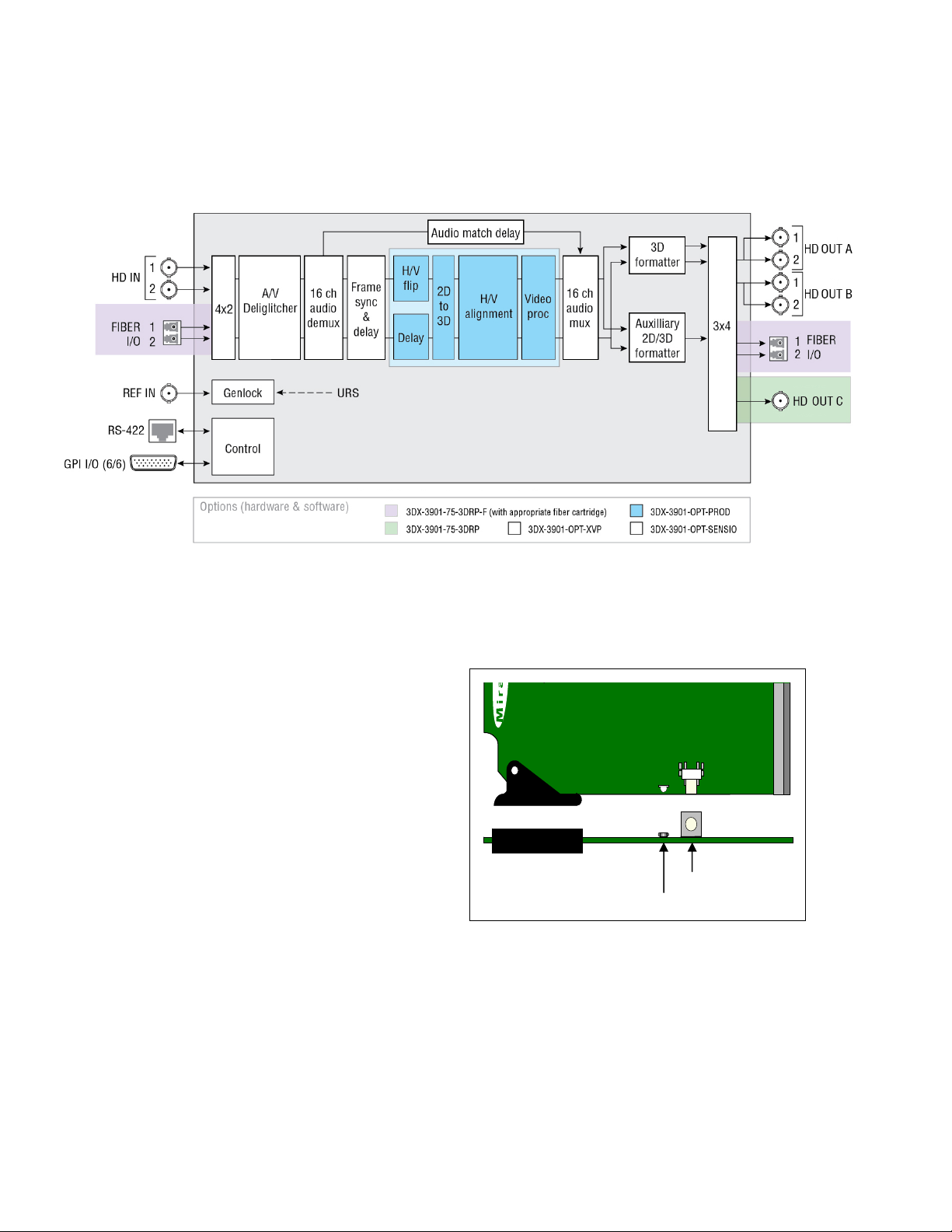
1.3 Block Diagram
The following block diagram shows the functionality of the 3DX-3901.
Figure 1.1 Functional block diagram of the 3DX-3901
1.4 Front Card-edge Interface
The front card-edge of the 3DX-3901 incorporates two
elements:
• Status LED (see section 3.2)
• Select Button (see section 3.3)
3DX-3901
Figure 1.2 Front card-edge layout
Status
Select
Select Button
Status LED
2 | 3DX-3901
Page 7
GUIDE TO INSTALLATION AND OPERATION
2 Installation
2.1 Installation in the Densité frame
The 3DX-3901 and its associated rear connector rear panel must be mounted in a Densité-3 frame. It is not
necessary to switch off the frame’s power when installing or removing the card. See the Densité-3 F rame manual
for detailed instructions for installing cards and their associated rear panels.
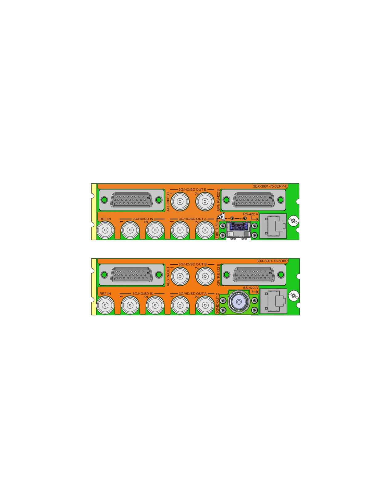
2.2 Rear Panels
The 3DX-3901 has multiple inputs and outputs, and making space for all the necessary connectors at the rear of
the frame requires a double-width rear panel.
With the double-width rear panel installed, the 3DX-3901 must be installed in the right-most of the two slots
covered by the panel in order to mate with the panel’s connectors.
NOTE: attempting to install the card in the wrong slot could result in damage to the edge connector of the
rear panel. BE CAREFUL
3DX-3901-75-3DRP-F
3DX-3901-75-3DRP
Figure 2.1 Rear Panels for the 3DX-3901
2.3 Connections
For external synchronization, connect a black studio reference signal to the BNC labeled REF IN.
• The reference input is terminated on the rear module.
The reference input must conform to SMPTE 170M/SMPTE 318M/ITU 624-4/BUT 470-6 for standard definition
signals and SMPTE 274M / SMPTE 296M for high definition signals and is used to phase the HD/SD SDI outputs to
the studio. A reference mismatch may occur if there is a difference between the input video format’s frame rate and
the reference format’s frame rate. When a mismatch occurs, the output will freeze to the reference frame rate and
produce an input error and the card-edge Status LED will turn red to indicate the mismatch.
3DX-3901 | 3
Page 8
GUIDE TO INSTALLATION AND OPERATION
Note that in the case of HD signals of the same frame rate, any reference signal may be used to genlock any output
signal, regardless of scan type (progressive or interlaced). When a 720p/tri-level sync reference signal is used with
an interlaced output, the output is synchronized but there may be a delay of one field depending on when the
synchronization started.
3G/HD/SD IN – Serial digital input (note: SD is future use for this connector)
Connect up to two serial digital video signals, conforming to the SMPTE 292M standard for HD input signals, to the
BNCs labeled 3G/HD/SD IN 1 and 2. The 3DX-3901 will automatically switch to the detected line/frame rate format.
3G/HD/SD OUT A and B – Serial digital video outputs (note: SD is future use for this connector)
The 3DX-3901 provides two pairs of 3G/HD/SD SDI video outputs on BNC connectors, labeled 3G/HD/SD SDI
OUT A1 & A2, and 3G/HD/SD SDI OUT B1 & B2. The SDI video signal conforms to the SMPTE 424M, SMPTE
292M or SMPTE 259M-C standard.
3G/HD OUT C – Serial Digital Auxiliary Output
The 3DX-3901 provides a third 3G/HD SDI video output, labeled 3G/HD SDI OUT C. The SDI video signal
conforms to the SMPTE 424M or SMPTE 292M standard.
In addition to Side by Side and Over/Under encoding, this auxiliary output provides a means of monitoring 3D
characteristics with Anaglyph and Disparity signals. Refer to Figure 3.4 for a complete list of all possible
configurations.
AES IN / OUT – (future use)
Fiber I/O – Fiber-optic inputs and outputs
Rear panels whose part number ends in –F incorporate a fiber optic interface. The interface consists of two parts:
• A socket on the rear panel into which an SFP interface module is plugged
• An SFP (Small Form-factor Pluggable) module into which the optical fibers are plugged, and which
incorporates the optical/electrical interface
The optical fibers must be terminated in an LC connector.
See Annex 2 for instructions on installing and removing the SFP interface module, and for plugging and unplugging
the LC-terminated fibers.
The current SFP modules supported are:
SFP Modules Description
SFP-RR-LC Dual Rx module with LC connector
SFP-TT-S13S13-LC Dual Tx module at 1310 nm with LC connector
SFP-RT-S13-LC Single Rx and Tx transceiver module at 1310 nm with LC connector
SFP-R-LC Single Rx module with LC connector
SFP-T-S13-LC Single Tx module at 1310 nm with LC connector
4 | 3DX-3901
Page 9
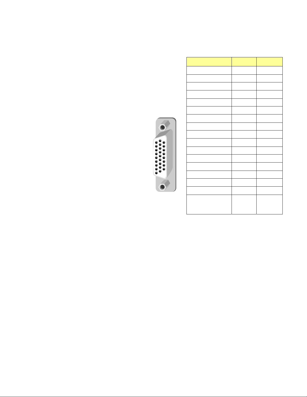
GPI / RS-422 B
GPI I/O section
The rear panel connector on a 26-pin D-SUB
provides:
• 6 GPI: 4 to recall user-configurable
presets and 2 for input selection.
• 6 GPO: output tallies for the selected
user preset and the input selection.
GPI and GPO are both contact closure to
ground, except GPI 1 and GPI 5 which can
also trigger events on contact release.
RS-422 B section – (future use)
RS-422 A – (future use)
GUIDE TO INSTALLATION AND OPERATION
Function
GPI 1 (USER1)
GPI 2 (USER2)
GPI 3 (USER3)
GPI 4 (USER4)
GPI 5 (INPUT 1)
GPI 6 (INPUT 2)
GPO 1 (USER1)
GPO 2 (USER2)
GPO 3 (USER3)
GPO 4 (USER4)
GPO 5 (IN1 SEL.)
GPO 6 (IN2 SEL.)
RS422-TX1 (+)
RS422-TX0 (-)
RS422-RX1 (+)
RS422-RX0 (-)
GND
I/O Pin #
In 14
In 5
In 15
In 6
In 7
In 17
Out 22
Out 23
Out 24
Out 25
Out 26
Out 18
Out 19
Out 11
In 12
In 21
-
1, 2, 3, 4,
8, 9, 10,
13, 16, 20
3DX-3901 | 5
Page 10
GUIDE TO INSTALLATION AND OPERATION
3 Operation
3.1 Control options
The 3DX-3901 can be controlled in two different ways:
• The local control panel and its push-buttons can be used to move through a menu of parameters and to adjust
parameter values (see section 3.3).
• Miranda’s iControl system can be used to access the card’s operating parameters from a remote computer,
using a convenient graphical user interface (GUI). (see section 3.4)
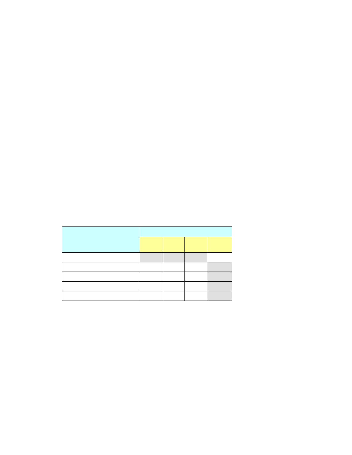
3.2 Card-Edge Status LED
The status monitor LED is located on the front card-edge of the 3DX-3901, and i s visible through the front access
door of the DENSITÉ frame. The chart shows how the various error conditions that can be flagged on the 3DX-3901
affect the LED status.
• If a cell in the chart is gray, the error condition cannot cause the LED to assume that status
• If more than one LED status is possible for a particular error condition, the status is configurable.
See Section 3.4.8 for details.
• The factory default status is shown by a , and forced status by an X
The LED will always show the most severe detected error status that it is configured to display, and in the cha rt
error severity increases from left to right, with green representing no error/disabled, and flashing red the mo st
severe error.
LED Color
Flashing
Alarm Name/Error Report
No Rear Detected
No IN 1 carrier
No IN 2 carrier
Video Error
Reference Mismatch
Green Yellow Red
Red
X
If the LED is Flashing Yellow, it means that the card is selected for local control using the Densité frame’s control
panel. See Section 3.3 for details.
6 | 3DX-3901
Page 11
GUIDE TO INSTALLATION AND OPERATION
3.3 Local control using the Densité frame control panel
3.3.1 Overview
Push the SELECT button on the 3DX-3901 card edge (Section 1.4) to assign the local control panel to operate the
3DX-3901. Use the control panel buttons to navigate through the menu, as described below.
All of the cards installed in a Densité frame are connected to the frame’s controller card, which handl es all
interaction between the cards and the outside world. There are no operating controls located on the cards
themselves. The controller supports remote operation via its Ethernet ports, and local operation using its integrate d
control panel.
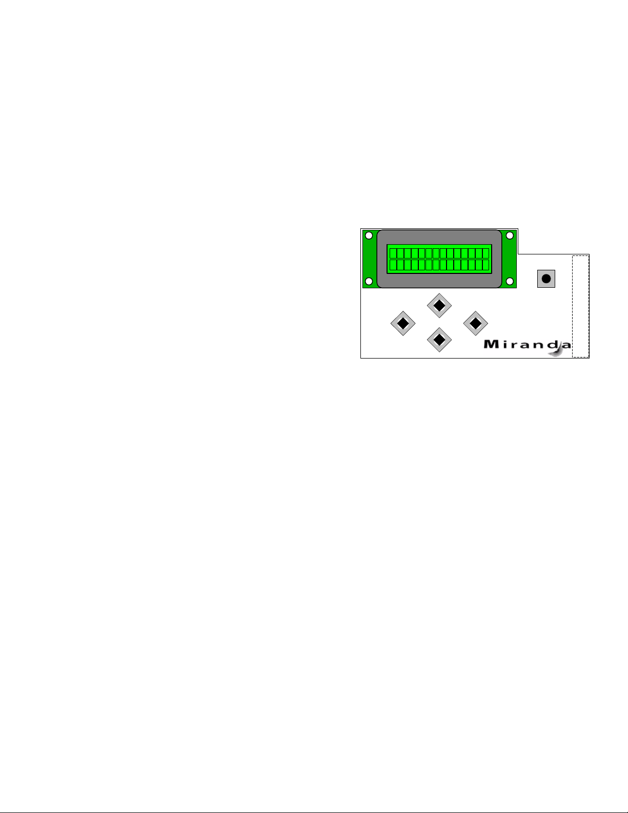
The local control panel is fastened to the controller card by a
hinged connector, and when installed is located in the front
center of the frame, positioned in front of the power supplies.
The panel consists of a display unit capable of displaying two
lines of text, each 16 characters in length, and five
pushbuttons.
The panel is assigned to operate any card in the frame by
pushing the SELECT button on the front edge of that card
ESC
+
-
• .Pushing the CONTROLLER button on the control panel
selects the Controller card itself.
• The STATUS LED on the selected card flashes yellow.
Figure 3.1 Densité Frame local control panel
The local control panel displays a menu that can be navigated using the four pushbuttons located beneath the
display. The functionality of the pushbuttons is as follows:
[+] [–] Used for menu navigation and value modification
[SELECT] Gives access to the next menu level. When a parameter value is shown, pushing this button once
enables modification of the value using the [+] and [–] buttons; a second push confirms the new value
[ESC] Cancels the effect of parameter value changes that have not been confirmed; pushing [ESC] causes
the parameter to revert to its former value.
Pushing [ESC] moves the user back up to the previous menu level. At the main menu, [ESC] does not
exit the menu system. To exit, re-push the [SELECT] button for the card being controlled.
If no controls are operated for 30 seconds, the controller reverts to its normal standby status, and the selected
card’s STATUS LED reverts to its normal operating mode.
CONTROLLER
SELECT
3.3.2 Menu for local control
The 3DX-3901 has operating parameters which may be adjusted locally at the controller card interface.
• Press the SELECT button on the 3DX-3901 front card edge to assign the Densité frame’s local control
panel to the 3DX-3901
• Use the keys on the local control panel to step through the displayed menu to configure and adjust the
3DX-3901.
The complete menu structure is shown in Annex 1 to this document, beginning on page 31.
3DX-3901 | 7
Page 12
GUIDE TO INSTALLATION AND OPERATION
3.4 Remote control using iControl
The operation of the 3DX-3901 may be controlled using Miranda’s iControl system.
• This manual describes the control panels associated with the 3DX-3901 and their use.
• Please consult the iControl User’s Guide for information about setting up and operating iControl.
In iControl Navigator or iControl Websites, double-click on the 3DX-3901 icon to open the control panel.
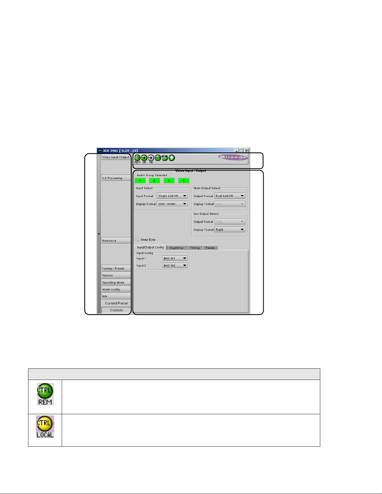
3.4.1 The iControl graphic interface window
The basic window structure for the 3DX-3901 is shown in figure 3.2. The window identification line across the top
gives the card type (3DX-3901) and the slot number where the card installed in its Densité frame.
2
Figure 3.2 3DX-3901 iControl graphic interface window
There are three main sections in the window, identified in figure 3.2:
Section 1. The Status Icon area shows a series of six icons that report the status of some card parameters. The
table shows the various forms that may appear (icons are numbered left to right):
Icon #1 – Manual Card Configuration
1
3
(green)
(yellow)
8 | 3DX-3901
Remote card control activated. The iControl interface can be used to operate the card
Local card control active, The card is being controlled using the Densité frame control
panel, as described in section 3.3. Any changes made using the iControl interface will have
no effect on the card.
Page 13

Icon #2 – Input 1 Status
Signal detected and valid
(green)
The format will be indicated beneath the icon
No carrier
(yellow)
Icon #3 – Input 2 status
Signal detected and valid
(green)
The format will be indicated beneath the icon
Signal unused because a single link input mode has been enabled
(gray)
No signal or Video/TRS error
(red)
GUIDE TO INSTALLATION AND OPERATION
Icon #4 – Reference
Signal detected and valid
(green)
• The format (HD or SD) will be indicated beneath the icon
No rear
(red)
Reference mismatch (frame rate does not match video input)
No reference detected
(gray)
Icon #5 – Operation Mode
Operation mode: process – normal processing of the input signal
(green)
Operation mode: Manual Freeze ON (see Sect. 3.4.2 – Freeze tab)
(yellow)
3DX-3901 | 9
Page 14

GUIDE TO INSTALLATION AND OPERATION
Icon #4 – Health Monitoring
Hardware OK
(green)
Hardware Health Monitoring fault detected
(red)
If this icon appears red, return the card to Miranda and specify the error code.
Move the mouse over an icon and a status message appears below the icon providing additional information. If
there is an error, the error status message appears in the message area without mouse-over.
• If there are multiple errors, the error messages cycle so all can be seen
• The icon whose status or error message is shown is highlighted with a mauve background
Section 2. The left-hand side of the panel contains a series of buttons that control the contents of the main
window (section 3). Click on one to access the indicated controls. The selected button is highlighted (darker) and
the main panel heading matches the button name.
• Some of the buttons will be different depending on which model of the 3DX-3901 is in use
• This section can be hidden or revealed by clicking the arrow icon at the center of the left side border.
Section 3. This section contains the main operating controls and displays for managing the 3DX-3901’ s feature
set. The contents are selected by clicking a button in section 2 on the left-hand side of the screen.
Each of the panels associated with the groups accessed from the buttons in section 2, and shown in section 3, is
described individually in the following sections.
3.4.2 The Video Input /Output panel
This panel provides resources for input and output
configuration.
These controls indicate if the 3D video will be carried on a
single link or a dual link transport. When a single link is
used, it is possible to select one of the Side by Side
modes or Over/Under depending on the 3D video
input/output. Otherwise, a Full value indicates this is a 2D
signal. In dual link mode, the card assumes each link
carries a full screen picture in the same video format.
See the diagram on the next page for an overview of the
formats that can appear at the inputs and outputs of the
3DX-3901.
Note that all VANC/HANC packets are passed through
untouched to the main left (1) and AUX outputs.
• Includes CC, TC, AFD, audio metadata, etc.
• All VANC/HANC data is frame accurate at all times.
• All VANC/HANC data is blanked when the input is
in error or during a manual freeze selection.
10 | 3DX-3901
Figure 3.3 Video I/O panel
Page 15

GUIDE TO INSTALLATION AND OPERATION
All data is bypassed except VPID packets describing 3G signals. If the output is set to 3G Lvl B DS, then a new
VPID is generated.
Figure 3.4 Overview of Input and Output formats
Input Select section
Input Format: Use the pulldown to select from among these options:
• Single Link HD – Selects input 1 for processing an d ignores input 2
• Dual Link HD – Both inputs 1 and 2 are selected for proces sing
• 3Gbps Lvl B - DS – Selects the 3G Level B Dual Stream signal connected to input 1 for processing and
ignores input 2
Display Format: This pulldown is only active when the Input Format is Single Link HD. Use the pulldown to select
from among these options:
• Full – Input signal does not have any inherent side-by-side or over-u nder stru cture.
• Normal Side by Side – Input signal is composed of 2 images, one on the left and one on the right.
3DX-3901 | 11
Page 16

GUIDE TO INSTALLATION AND OPERATION
®
• SENSIO
3D – Input signal is composed of 2 images encoded using the SENSIO® 3D algorithm with one
image on the left and one image on the right.
• Over – Under – Input signal is composed of 2 images, one on the top half of the signal and one on the bottom
half of the signal. This format is only available for progressive inputs.
When the Input Format is Dual Link HD, the display format is Full by default.
Main Output Select section
Output Format: Use the pulldown to select from among these options:
• Single Link HD
• Dual Link HD
• 3Gbps Lvl B - DS
Display Format: This pulldown is only active when the Output Format is Single Link HD. Use the pulldown to select
from among these options:
• Full – Output signal has no encoding.
• Normal Side by Side – Output signal is encoded side -by-side with incoming left and right signals.
®
• SENSIO
3D – Output signal is encoded side-by-side, using the SENSIO® 3D algorithm, with incoming left
and right signals.
• Over – Under – Output signal is encoded over-under with incoming left and right signals. This format is only
available for progressive outputs.
When the Output Format is Dual Link HD, the display format is Full by default.
Aux Output Select section
Output Format: The output format always follows the input format. In the future, it will be possible to change the
output format of the auxiliary output.
Display Format: Use the pulldown to select from among these options:
• Normal Side by Side – Aux Output signal is encoded side-by-side with incoming left and right signals.
®
• SENSIO
3D – Aux Output signal is encoded side-by-side, using the SENSIO® 3D algorithm, with incoming
left and right signals.
• Anaglyph (color) – Aux output is an Anaglyph representation of the incoming left and right signals.
• Disparity (L-R) – Left minus right – Aux Output signal is the difference between incoming left and right
signals.
• Left – Aux Output signal is fed with input left signal.
• Right – Aux Output signal is fed with input right signal.
• Over – Under – Aux Output signal is encoded over-under with incoming left and right signals. This format is
only available for progressive outputs.
• 3Gbps Lvl B - DS
Swap Eyes
Click the checkbox to interchange the two eye signals – left becomes right and right becomes left. This is done at
the card input and it precedes any other processing. If the input is Side by Side on a single link, the eyes will be
swapped.
12 | 3DX-3901
Page 17

GUIDE TO INSTALLATION AND OPERATION
Input/Output Config tab
The Input Config pulldowns allow the user to select between sources (both electrical and optical if available) for
inputs 1 and 2.
It must be noted that the auxiliary output is not available when a fiber module is used, as there is not room for
both connectors on the rear panel.
The Fiber Output Config pulldowns allow the selection of outputs on the fiber optic channels, if available. The
choices are OFF, LEFT, RIGHT and AUX. Unavailable choices are shown in red.
Optic Fiber Module: The Detected text box shows the type of fiber optic module installed in the rear panel, if any.
Deglitcher tab
When the Deglitcher is ON, the card supports a hot-switch
between two signals on the same input without producing
a freeze on the frame sync, and without producing artifacts
on the output.
The deglitcher must be disabled when the input is
asynchronous to the reference. Otherwise, it will
create audio and video glitches at the output.
Mode: select OFF or ON from the pulldown.
• Note that the Deglitcher cannot be enabled for
1080p23, 1080p23sF, 1080p25 and 1080p29
sources
Figure 3.5 Input / Output - Deglitcher tab
For this mode to function correctly, the following
requirements must be met:
• The two inputs must be synchronized to the reference
• They must be phased within one line of each other
• They must be phased to within +/- ½ line of the HREF of the reference signal
The offset from the VREF can be variable, but a distance of greater than 10 lines could create an artifact in the
active video. If the two signals are more than 1 line apart, we will see a vertical jump at the moment of switching
that is proportional to the number of vertical lines of offset between the two signals. This will last for only one frame.
There may also be problems in the transition when in the AFD automatic or forced mode.
When a reference is present and the deglitcher is active, the card reports the difference in timing between the input
and the reference when the transition occurs.
• If the reference is missing when the deglitcher is activated, the Input timing to reference box will indicate
“Missing reference” in red, and the reference status icon at the top of the iControl window will turn red and
show the message “Reference missing”.
• If the deglitcher is OFF, the reference status icon will be grey, and its message will read “Reference absent”
3DX-3901 | 13
Page 18

GUIDE TO INSTALLATION AND OPERATION
To perform a glitch-free switch between two sources, they must be in the same clean switch region. A clean switch
region is contained within ± ½ line about an H=0 point in the reference signal, as shown by the dotted lines in the
figure. There is a clean switch region centered on every H interval. As you can see, vertical alignment with the
reference is not important for the deglitcher to operate properly.
You may switch between signals A, B or C, without any glitch, and also between signals DE and signals FG.
Any other transition, like AD, will cause a vertical image shift for one frame.
To determine whether a clean hot switch is possible, you need to determine whether the two input signal s lie in the
same clean switch region. There are two ways to measure the position of the signals with respect to the reference:
• Use the deglitcher tab in iControl (InputDeglitcher)
• Use the controller menu in Appendix 2 (videotimingin timing to ref).
When the deglitcher mode is on, each of these sources will display the alignment offset between the reference
signal and the input signal. Knowing the offset for both input signals, you can determine if they are in the same
clean switch region. If so, any hot-switch between those two signals will be glitch less.
To determine the limits of a clean switch region, you must know the input’s line length in μs. The first region is
delimited by +½ line and -½ line of the reference. For example, with a 1080i59 signal the line length is 29.6 μs and
so the first region lies between -14.8 μs and 14.8 μs. Other regions can be found by adding or removing a multiple
of line length to the two boundaries.
Example: for a 1080i59 input signal, we have these clean switch regions:
-1 line and -14.8 μs to 0 line and -14.8 μs
0 line and -14.8 μs to 0 line and 14.8 μs
0 line and 14.8 μs to 1 line and 14.8 μs
etc.
14 | 3DX-3901
Page 19

GUIDE TO INSTALLATION AND OPERATION
Practical examples:
Example 1: we have two 1080i59 sources, one that indicates an offset of -10 μs with respect to the reference (A)
and the other an offset of -25 μs (B). We know that a clean switch region limit is present at -½ line, which
corresponds to -14.8 μs. We can now determine that this switch will not be clean, because the two sources are on
opposite sides of the limit, and are therefore not in the same clean switch region.
Example 2: We have two 1080i59 sources, one that indicates an offset of 25μs with respect to the reference (A)
and the other an offset of 17μs (B). We know that a clean switch region limit is present at + ½ line and another one
at ½ line plus one line. These correspond to 14.8μs and 44.4μs. We can now determine that this switch will be
clean, because the two sources are inside the same clean switch region.
Timing tab
The Timing tab provides access to timing adjustments
which affect the signal outputs. There are two slider
controls, each with a data reporting box which shows the
current value, and into which values can be typed directly.
The total delay is reported at the top of the window.
Vertical (lines): With this adjustment, a value ranging from
–16 to +15 lines compared to the reference or the
processing delay, may be set. This adjustment can be
used in conjunction with the horizontal timing adjustment.
Figure 3.6 Input/Output - Timing tab
3DX-3901 | 15
Page 20

GUIDE TO INSTALLATION AND OPERATION
Horizontal (µs): With this adjustment, a value ranging from zero to the equivalent of 1 horizontal line in the current
operating format compared to the reference or the frame boundary may be set.
Additional Frame Delay: This parameter affects the overall processing delay of the card. It adds supplemental
frame delay to the current processing delay. This parameter will add a delay ranging from 0 to 6 frames (steps of 33
ms in 59.94 Hz and 40 ms in 50 Hz) to the current processing delay. Without a reference, the normal processing
delay is 1 frame. You can extend this delay up to 7 frames if the additional delay is 6. With a reference, up to 6
frames can be added to the frame sync delay which depends on the timings between the input and the reference.
Freeze tab
Freeze type: This is a pull-down menu with four options –
FIELD 1, FIELD 2, FRAME and BLACK. It determines the
manner in which the 3DX-3901 responds to a manual
freeze, a video input switch (“hotswitch” as defined by
SMPTE recommended practice RP-168, revised January
2002), a loss of input signal or other input errors. The four
possible options yield the following results:
Figure 3.7 Input/Output - Freeze tab
Freeze Option Auto Freeze Mode Manual Mode
• Field 1
• Field 2
• Frame
• Black
Auto Freeze: This pulldown (ON/OFF) enables or disables the auto freeze function. In Auto Freeze mode, a
reference must be present to ensure a glitchless output when a freeze is activated. There are only two freeze
possibilities in Auto mode: freeze to last valid Field or freeze to black. When Auto Freeze mode is disabled, the
content of the active picture will reflect whatever garbage is present at the input but, if a reference is present, the
output synchronization will be maintained to avoid unlocking downstream equipment.
Activate Manual Freeze: Select this checkbox to immediately freeze the output according to the mode selected in
the Freeze Type pull-down.
Note: The manual freeze setting is saved in the non-volatile memory of the card. If the manual freeze is activated
and the power is cycled, the card will start in freeze mode at the next power-up and the output will be invalid. Just
turn off the manual freeze to restore the output. In all cases, audio will be muted when there is an input error. See
the audio section for more information.
Freeze to last valid FIELD
Freeze to BLACK
Freeze to last valid FIELD 1
Freeze to last valid FIELD 2
Freeze to last valid FRAME
16 | 3DX-3901
Page 21

GUIDE TO INSTALLATION AND OPERATION
3.4.3 The 3-D Processing panel
The 3-D processing that is available is a function of the
input format, as selected in the Video I/O tab.
• This panel is only available when the 3D Prod option
has been activated
2-D to 3-D tab
The 3DX-3901 can convert a 2-D video feed carried on a
single link transport to a 3-D output format. It is intended to
replace a 3-D camera in long shot applications. It does not
really create 3-D perspective out of a 2-D image.
If input is Single Link HD with a Full Display Format, the 2D to 3-D tab is enabled.
This tab provides resources to generate a pseudo-3D
effect by moving the apparent image plane away from the
video display surface.
Use the pulldown in the upper right of the tab to Enable or
Disable the 2-D to 3-D processing.
Depth Adjustment (Pixel) – use the slider, or type directly
into the data box, to offset the left eye and right eye
images.
Offset Replacement – define the content that will replace the moved image. Fixed to Black at present.
Apply Offset on – select whether to move the Left eye
image, the Right eye image, or both eye images.
Orientation tab
If input is Dual Link HD or Single Link HD with a side-byside or over-under Display Format, the Orientation tab is
enabled.
This panel provides resources to compensate for image
positioning, sizing and orientation issues between the
incoming Left eye and Right eye signals. These anomalies
may arise in the stereoscopic camera itself, or in the signal
path between the camera and the 3DX-3901.
Flip – The image may arrive with one eye flipped
horizontally and/or vertically in comparison to the other,
usually as a consequence of the stereoscopic camera’s
optical configuration.
• Examine the image using a monitor connected to
the Aux Output, and determine which image is
incorrectly oriented.
• Use the Horizontal and Vertical checkboxes to apply
the necessary flips to the image.
Figure 3.8 3-D Processing - 2-D to 3-D tab
Figure 3.9 3-D Processing - Orientation tab
3DX-3901 | 17
Page 22

GUIDE TO INSTALLATION AND OPERATION
H/V Alignments – Once the images are correctly oriented, it may be necessary to move the Left or Right eye image
horizontally (in pixels) or vertically (in lines) so that the two images are exactly overlapped. This is used to
compensate for misaligned cameras on the rig.
• Examine the image using a monitor connected to the Aux Output, and view the overlapped images. Disparity
mode may be useful as it will show overall image alignment errors.
• Use the sliders or type directly into the data boxes to
get the best match between images.
HIT tab
HIT stands for Horizontal Image Translation.
This tab provides resources, during Dual Link operaton,
to adjust the image depth positioning by moving the
apparent image toward or away from the viewer. This is
accomplished by offsetting the eye images by up to 30
pixels to change the apparent vanishing point.
Horizontal (Pixel) – use the slider, or type directly into the
data box, to offset the left eye and right eye images.
Offset Replacement – define the content that will replace
the moved image. Fixed to Black at present.
Apply Offset on – select whether to move the Left eye
image, the Right eye image, or both eye images.
Proc tab
Figure 3.10 3-D Processing - HIT tab
This tab provides Proc Amp resources to modify the video
component signals to correct for gain and color balance
discrepancies. Matching the color and gray scale of the
two eye signals is an important aspect of effective
stereoscopic presentation.
Proc Mode – choose whether to make corrections in
YCrCb mode or RGB mode. The contents of the Basic and
Advanced tab will reflect the choice made here.
Proc Eye – select Left eye or Right eye to apply the proc
amp correction. Note that only one eye can be adjusted,
so pick the best quality image as a reference and adjust
the other for the best match.
Basic tab – these controls are provided:
Y Cr Cb R G B
All Gain All Gain
Y Gain G Gain
Chrominance Gain B Gain
Black Offset R Gain
Hue (degrees)
Figure 3.11 3-D Processing - Proc / Basic tab
18 | 3DX-3901
Page 23

Advanced tab – these controls are provided:
Y Cr Cb R G B
Y Gain G Gain
Cb Gain B Gain
Cr Gain R Gain
Y Offset G Offset
Cb Offset B Offset
Cr Offset R Offset
Note that settings made in one tab appear in both. Note also
that while all of the adjustments in the Advanced tab are
independent, the All Gain adjustments in the Basic tab
interact with other settings on that tab.
If you change some settings and attempt to switch
modes, you may be asked to confirm your changes
since they will affect image quality.
GUIDE TO INSTALLATION AND OPERATION
Figure 3.12 3-D Processing - Proc / Advanced tab
3.4.4 The Reference panel
The reference is used to gracefully handle misaligned
hot switches at the input or to use the built-in frame
synchronizer. -
This panel allows the selection of the reference to be used
by the 3DX-3901.
Use the radio buttons in the Reference Source area to
select from the following options:
• Auto – this mode selects the first source detected in
this order of priority:
o External Reference input
o URS
o Selected Input signal
• External – selects the signal connected to the rearpanel REF IN connector
• URS (Universal Reference Signal) – selects the
internal reference from the backplane
• Input – uses the currently-selected input signal.
URS Format – use the radio buttons in the URS Format
area to select whether the URS is OFF, 29.97 Hz or 25
Hz.
• When URS is OFF, the URS reference format
source cannot be selected, and will also be ignored
by the automatic detection mode.
Note that there is no external reference or URS support
for 1080p23, 1080p23sf, 1080p25 or 1080p29 inputs.
Figure 3.13 Proc Amp mode change warning
Figure 3.14 Reference panel
3DX-3901 | 19
Page 24

GUIDE TO INSTALLATION AND OPERATION
3.4.5 The Factory / Presets panel
Factory
The 3DX-3901 maintains a “Factory Default” alignment in
its memory, to which it can be restored at any time. Both
Card Parameters and Card Alarms are available.
• Select the checkboxes to determine whether the
Parameters and/or Alarms will be loaded
• Click the Load Factory button to load the card with
the Factory default parameters and/or alarms
User Presets
The User Preset controls allow the user to save and
recover all configuration settings on the card.
Select any one of the five presets using the pulldown list.
The name of the currently-selected User Preset is shown
on the on the pulldown icon (e.g. User1, User2,… User5)
• Click Load to load the contents of the selected User
Preset into the 3DX-3901. All parameter settings
and values will be replaced by the contents of the
selected User Preset.
• Click Save to store the current parameter settings
and values from the 3DX-3901 into the selected
User Preset. The existing contents of the preset will be overwritten.
The user can change the labels for the user presets:
• Click the Edit Presets Label… button at the bottom of the panel
• In the Presets pop-up, click on a label name, and type a new name
• Click OK to confirm the new name(s) and close the pop-up
• Click Cancel to close the pop-up and leave the names unchanged
GPI
GPI inputs 1 to 4 can be used to activate the user presets.
Select the checkboxes to enable this functionality as required.
• Note that GPI 1 has a dual function – it loads User Preset 1 when activated, and loads User Preset 5 when
released.
Profiles
This section provides the option to save and recover the entire card configuration (including user pre sets if desired)
on an external disk, or to copy it to another 3DX-3901 card.
Click on Profiles to open the Profile Copy window.
Figure 3.15 Factory / Presets panel
Figure 3.16 Edit Presets Label…
20 | 3DX-3901
Page 25

GUIDE TO INSTALLATION AND OPERATION
Figure 3.17 Profile Copy for Card window
Copy profile from
This line shows this 3DX-3901 card, and identifies it by App server, Densité frame and slot number, card type and
firmware version.
The Profile column has a pulldown that allows you to select which profiles you will work with, and gives these
choices:
• Current, User1, User2, User3, User4, User5, All
The Select column includes a checkbox (preselected checked) to confirm that you want to work with the current
card.
Save Profile to Disk…
Click this button to open a Save dialog allowing you to
specify a file name and location to which the selected profiles
for this card will be saved.
Hint - It is a good idea to create a folder for these files,
because they are not explicitly identified as 3DX-3901
profiles, and will be difficult to find and identify if not clearly
named and conveniently located.
• Click the save button once the name and location have
been identified in the Save box
• If the file is saved correctly, the Transfer Status box on
the right of the Copy profile from line will indicate
Succeeded against a green background
Figure 3.18 Save Profile to Disk dialog
• If the file was not saved for some reason, the Transfer Status box to the right of the Copy profile from line will
indicate Failed against a red background
3DX-3901 | 21
Page 26

GUIDE TO INSTALLATION AND OPERATION
Restore profiles from disk…
Click this button to open an Open dialog box within which you
can locate and select a valid 3DX-3901 profile file.
• Click Open to read the contents of the file and to
reconfigure this 3DX-3901’s profiles according to its
contents
• While the reconfiguration is in progress, the Transfer
Status box on the right of the Copy profile from line will
indicate Working against a yellow background
• When the reconfiguration is complete, the Transfer
Status box on the right of the Copy profile from line will
indicate Succeeded against a green background
Figure 3.19 Restore Profiles from Disk dialog
Copy profile to section
This line shows other 3DX-3901 cards that are available on the iControl network, each identified by App server,
Densité frame and slot number, card type and firmware version.
The Profile column shows the same information as is shown for the current card in the Copy profile from line, i.e.
one of the following:
• Current, User1, User2, User3, User4, User5, All
The Select column includes a checkbox to identify which 3DX-3901 cards you wish to copy profiles into from the
current card.
• For convenience, a Select all checkbox is provided in the column header
Click Copy to copy the selected profiles from this card into the selected other 3DX-3901 cards
• While the profile copy operation is in progress, the Transfer Status box on the right of the Copy profile to line
will indicate Working against a yellow background
• When the profile copy operation is complete, the Transfer Status box on the right of the Copy profile to line
will indicate Succeeded against a green background
3.4.6 The Options panel
Three options are available for the 3DX-3901:
• XVP Option (3DX-3901-OPT-XVP)
• Prod Option (3DX-3901-OPT-Prod)
• Sensio Option (3DX-3901-OPT-Sensio)
To activate each of these options, you must
• Obtain a license key from Miranda Technologies Inc.
• Type the license key in the box
• Click on ENABLE OPTION to enable the option’s features.
22 | 3DX-3901
Page 27

XVP Option
The XVP option permits the user to operate this 3DX-3901
as a full XVP-3901 Up, Down & Cross Converter with
audio processor included.
Installing this option enables the Operating Mode button in
the 3DX-3901 control panel.
See section 3.4.7 on page 24 for important information
about this operating mode.
Prod Option
This option enables the 3D processing functions of the
3DX-3901. These functions are shown in blue in the block
diagram on page 2, and are accessed through the 3D
Processing panel (see section 3.4.3 beginning on page 17)
GUIDE TO INSTALLATION AND OPERATION
Figure 3.20 Options panel - XVP Option
Figure 3.21 Options panel - Prod Option
3DX-3901 | 23
Page 28

GUIDE TO INSTALLATION AND OPERATION
Sensio
®
This option enables the SENSIO
3D processing
algorithm on this 3DX-3901.
Figure 3.22 Options panel - Sensio Option
3.4.7 The Operating Mode panel
The 3DX-3901 may be operated as an XVP-3901 Up,
Down & Cross Converter, with audio option included,
when the XVP option (see page 22) is activated.
• When the Start in XVP mode… button is clicked, the
iControl panel will close, and the card will be
restarted.
• The card GUI must be reopened by the user. It will
still have the same name and location – i.e. it will
still be identified as a 3DX-3901 – but the GUI that
opens will be an XVP-3901 GUI.
• Consult the XVP-3901 manual for operating
instructions
• The XVP-3901 GUI will include a button allowing the
card to be returned to 3DX operating mode – this
button does not appear in a standard XVP GUI.
It important to note that:
• Configuration settings are saved independently for
both operating modes, so you can move back and
forth between modes without losing any
configuration data.
• Firmware upgrades must be made in the 3DX
operating mode
Figure 3.23 Operating Mode panel
24 | 3DX-3901
Page 29

GUIDE TO INSTALLATION AND OPERATION
3.4.8 The Alarm Config panel
This panel allows the alarm reporting of the 3DX-3901 to be configured. The panel opens in a new window when
the button is clicked, and can be resized if needed.
The panel is organized in columns.
Status/Name
This contains an expandable tree listing all the alarms reported by this 3DX-3901 card.
• Each alarm name includes an icon that shows its current status
• Some alarms may be text-only and the alarm status is shown in the name and not by a status icon
The Card LED, Overall alarm and GSM contribution columns contain pulldown lists that allow the level of
contribution of each individual alarm to the alarm named in the column heading to be set.
Figure 3.24 Alarm Configuration Panel
• Click on the alarm icon in the column to open the list for an alarm
CARD LED
This column allows configuration of the behavior of the 3DX-3901’s card-edge Status LED. The Card LED status
is shown at the bottom of the alarm tree in the Status/Name column.
Overall Alarm
This column allows configuration of the contribution of each individual alarm to the Overall Alarm associated with
this card. The Overall Alarm is shown in the upper left corner of the iControl panel, and also appears at the
bottom of the Status/Name column.
GSM Contribution
This column allows configuration of the contribution of each individual alarm to the GSM Alarm Status associated
with this card. GSM is a dynamic register of all iControl system alarms, and is also an alarm provider for external
applications. The possible values for this contribution are related to the Overall alarm contri bution:
3DX-3901 | 25
Page 30

GUIDE TO INSTALLATION AND OPERATION
• If the Overall alarm contribution is selected as Disabled, the GSM alarm contribution can be set to any
available value
• If the Overall alarm contribution is selected as any level other than disabled, the GSM cont ribution is forced to
follow the Overall Alarm.
Levels associated with these alarms:
The pulldown lists may contain some or all of the following options:
The alarm makes no contribution (black icon)
The alarm is of minor importance (yellow icon)
The alarm is of major importance (orange icon)
The alarm is of critical importance (red icon)
The alarm exists but has no effect (used for text and composite alarms)
Shortcut: if you click on “Set All” in one of the columns beside a major heading in the Status/Name colu mn),
you will open a pulldown list that lets you assign a level to all alarms in that section of the column simultaneously.
Log Events
iControl maintains a log of alarm events associated with the card. The log is useful for troubleshooting and
identifying event sequences. Click in the checkbox to enable logging of alarm events for each individual alarm.
At the bottom of the window are several other controls:
Overall alarm and GSM contribution follow card LED
Click in the checkbox to force the Overall alarm and
GSM contribution to be identical to the Card LED status
• All Overall alarms for which there is a Card LED
alarm will be forced to match the Card LED alarm
• All Overall Alarms for which there is no Card LED
alarm will be forced to Disabled
A warning box will open allowing you to confirm the
action, since it will result in changes to the configuration
and there is no undo function.
Figure 3.25 Warning for Follow LED change
26 | 3DX-3901
Page 31

GUIDE TO INSTALLATION AND OPERATION
Copy to other cards
Click this button to open a panel that allows the alarm
configuration set for this card to be copied into another
3DX-3901 card.
• Select one or more destination cards from the list
in the window by clicking in the checkboxes, or all
of them by clicking in the All checkbox
Figure 3.26 Copy to other cards
Get alarm keys
Click this button to open a save dialog where you can
save a file containing a list of all alarms on this card and
their current values, along with an Alarm Key for each.
The alarm keys are useful for system integration and
troubleshooting.
• The file is saved in Excel.csv format
Figure 3.27 Get alarm keys save dialogue
OK, Apply, Cancel
• OK accepts the settings and closes the window once the card confirms that ther e are no errors.
• Apply accepts the settings, but leaves the window open
• Cancel closes the window without applying any changes, and leaves the previous settings intact.
3DX-3901 | 27
Page 32

GUIDE TO INSTALLATION AND OPERATION
3.4.9 The Info panel
When the 3DX-3901 is included in an iControl
environment, certain information about the card should be
available to the iControl system. The user can enter labels
and comments that will make this card easy to identify in a
complex setup. This information is entered via the Info
control panel. This panel also shows other information
about the card.
Rear Type: Identifies the installed rear panel
Optical Fiber Module:
Identifies the SFP module, if any, that is
installed in the rear panel
Label: type the label that appear for this 3DX-3901
when it appears in iControl applications
Short Label type the short-form label that iControl uses
in some cases (8 characters)
Source ID type a descriptive name for this 3DX-3901
Comments: type any desired text
The remaining data boxes show manufacturing
information about this card.
• Details…: Reports the Firmware version, service
version, and panel version for this card
• Advanced…: Shows the Miranda LongID for this card.
The Miranda LongID is the address of this 3DX-3901 in
the iControl network.
(Inputs and Outputs windows – future use)
Figure 3.28 Info panel
Figure 3.29 Details window
28 | 3DX-3901
Figure 3.30 Advanced window
Page 33

GUIDE TO INSTALLATION AND OPERATION
• Remote System Administration – opens the Joining Locators data
box, which lists remote lookup services to which this 3DX-3901 is
registered.
Add: Force the iControl service for this 3DX-3901 to register itself on
a user-specified Jini lookup service, using the following syntax in the
data box:
jini://<ip_address>
where <ïp_address> is the ip address of the server running the
lookup service, e.g.:
Figure 3.31 Joining Locators window
Remove: select one of the services listed in the window by clicking on it, and click Remove t o open a q uery
box allowing you to delete it from the window.
3DX-3901 | 29
Page 34

GUIDE TO INSTALLATION AND OPERATION
4 Specifications
VIDEO INPUT (2) / OUTPUT (3)
Signal: SMPTE 292M(1.485, 1.485/1.001 Gbps)
SMPTE 424M (2.970, 2.970/1.001 Gbps)
Supported formats: HD: SMPTE 274M: 1080i59.94, 1080i50, 1080p23.98, 1080p23.98sf,
1080p25, 1080p29
HD : SMPTE 296M : 720p59.94, 720p50
HD: SMPTE 425B Level B Dual Stream: 1080p59.94, 1080p50 with
supported embedded streams listed above.
Cable length: 150 m Belden 1694A at 1.485 Gbps
120 m Belden 1694A at 2.970 Gbps
Return loss: >15 dB up to 3 GHz
Jitter: HD/SD: <0.2 UI
REFERENCE INPUT
Signal: SMPTE 170M/SMPTE 318M/ITU 624-4 black burst
SMPTE 274M / SMPTE 296M tri-level sync
Return loss: >35 dB up to 5.75 MHz
VIDEO PROCESSING PERFORMANCE
Signal path: 10 bits minimum
Latency: 2 frames in all modes
GPI
Connector: 26-pin D-Sub, opto-isolated
GPI in: 6
GPI out: 6
RS-422
Connector: RJ-45
FIBER
SFP optical module documentation
ELECTRICAL
Power: 25 W
30 | 3DX-3901
Page 35

GUIDE TO INSTALLATION AND OPERATION
3
3901 | 3
, FLASHING RED]
, FLASHING RED]
, FLASHING RED]
, FLASHING RED]
, RED, FLASHING RED]
FIBER NO SIGNAL/REF FORMAT/ REF MISMATCH
GPI 2 ACTIVATION [LOAD USER2, DISABLE]
ANNEX 1 – 3DX-3901 User interface
Menu level LEV1 LEV2 LEV3 LEV4 VALUES Conditions
Card Status STATUS GENERAL STATUS REAR TYPE / OPTIC TYPE / FAN ERROR 1 or 2/ CRITICAL HEALTH (XXXX XXXX)
VIDEO STATUS IN NO CARRIER/ IN FORMAT/ IN TRS ERROR/ IN2 FMT MISMATCH/
AUDIO STATUS GROUP PRESENCE 1 to 4
Configuration load CONFIG LOAD [USER1, USER2, USER3, USER4, USER5]
Configuration save SAVE [USER1, USER2, USER3, USER4, USER5]
GPI Enable GPI GPI 1 ACTIVATION [LOAD USER1, DISABLE]
GPI 1 RELEASE [LOAD USER5, DISABLE]
GPI 3 ACTIVATION [LOAD USER3, DISABLE]
GPI 4 ACTIVATION [LOAD USER4, DISABLE] Input Selection INPUT SELECT INPUT FORMAT [SINGLE LINK HD, DUAL LINK HD]
DISPLAY FORMAT [FULL, NORM SIDE/ SIDE, SENSIO SIDE/SIDE, OVER / UNDER] Input Configuration CONFIG INPUT 1 [BNC IN1, BNC IN2, FIBER IN1, FIBER IN2] Requires –F rear module
INPUT 2 [BNC IN1, BNC IN2, FIBER IN1, FIBER IN2] Requires –F rear module SWAP EYE [OFF, ON] Output Configuration OUTPUT MAIN SELECT OUTPUT FORMAT [SINGLE LINK HD, DUAL LINK HD]
DISPLAY FORMAT [FULL, NORMAL SbS, SENSIO SbS, OVER - UNDER] AUXSELECT OUTPUT FORMAT [1080i, 720p, 1080p LEVEL A, 1080p LEVEL B]
CONFIG FIBER OUT 1 * [OFF, MAIN LEFT, MAIN RIGHT, AUX OUT] Requires –F rear module
DISPLAY FORMAT [NORMAL SbS, SENSIO SbS, ANAGLYPH, DISPARITY (L-R),
LEFT, RIGHT, OVER / UNDER]
FIBER OUT 2 * [OFF, MAIN LEFT, MAIN RIGHT, AUX OUT] Requires –F rear module Reference Source REFERENCE SOURCE [AUTO, REF, URS, IN]
URS rate URS [OFF, URS-29.97, URS-25]
Deglitcher mode DEGLITCHER [OFF, ON]
Timing in pixel steps TIMING VERTICAL [-16, -15, …,0…, 15] unit=LINE
HORIZONTAL [0,.., 29.65] step=13.5ns unit=µs
Additional Frame Delay FRAME [0, 1, …, 6]
Input Timing to REF IN 1 TIME TO REF [display timing]
Input Timing to REF IN 2 TIME TO REF [display timing] Freeze Type FREEZE TYPE [FIELD1, FIELD2, FRAME, BLACK]
Automatic Freeze on Error AUTO [OFF, ON]
Manual Freeze MAN [OFF, ON] Audio/Video Test TEST PATTERN [OFF, ON] CONFIG ALARMS CTRL GPI [OFF, ON]
Carrier Detect 1 Error CARD LED CD1 ERROR [GREEN, YELLOW, RED, FLASHING RED]
Carrier Detect 2 Error CD2 ERROR [GREEN, YELLOW, RED, FLASHING RED]
Video Input 1 Error VIDEO ERROR 1 [GREEN, YELLOW, RED, FLASHING RED]
Video Input 2 Error VIDEO ERROR 2 [GREEN, YELLOW, RED, FLASHING RED]
In 2 format mismatch in dual link IN2 FMT MISMATCH [GREEN, YELLOW, RED
Fiber selection Error FIBER SELECT ERR [GREEN, YELLOW, RED
Reference is missing REF MISSING [GREEN, YELLOW, RED
Reference mismatch REF MISMATCH [GREEN, YELLOW, RED
Card in manual freeze MANUAL FREEZE [GREEN, YELLOW, RED, FLASHING RED]
Card in test mode TEST MODE [GREEN, YELLOW
Firmware Version VERSION 3DX-3901 : XXX XVP MODE Option OPTIONS XVP MODE ON/OFF Key:XX.XX.XX.XX
Prop Option PROD ON/OFF Key:XX.XX.XX.XX
Sensio Option SENSIO ON/OFF Key:XX.XX.XX.XX
DX-
1
Page 36

GUIDE TO INSTALLATION AND OPERATION
RealD Option REALD ON/OFF Key:XX.XX.XX.XX
Factory Card Parameters FACTORY RESET CARD PARAMETERS [NO, YES]
Factory Led Alarms CARD LED ALARMS [NO, YES] Note: Some menu items may not be present depending on card model, input format, or card configuration.
32 | 3DX-3901
Page 37

GUIDE TO INSTALLATION AND OPERATION
ANNEX 2 – Installing the Optical Interface
Installing and removing the Fiber I/O interface cartridge requires special care. This annex describes the process.
Some rear panels used with the 3DX-3901 incorporate a fiber optic interface. The interface consists of two parts:
• A socket on the rear panel into which an SFP interface module is plugged
• An SFP (Small Form-factor Pluggable) module into which the optical fibers are plugged, and which
incorporates the optical/electrical interface
Cautions and Warnings
SFP Transmitter modules contain a class 1 laser, which emits invisible radiation whenever the module is
powered up. Because the SFP is hot-swappable, the module may be powered up as soon as it is installed.
DO NOT LOOK INTO AN OPERATING SFP MODULE’S CONNECTORS, AS EYE DAMAGE MAY RESULT.
The SFP module is sensitive to electrostatic discharge (ESD). It is recommended that you use an ESDpreventive wrist strap grounded to the Densité chassis while handling the SFP module.
SFP modules are subject to wear, and their useful lifetime is reduced each time they are inserted or
removed. Do not remove them more often than is absolutely necessary.
Never remove or install an SFP module with the fiber optic cables connected. Damage to the cables could
Installing an SFP module
result.
The presence of dust and debris can seriously degrade the performance of an op tical interface. It is
recommended that you insert a dust plug into the SFP module whenever a fiber optic cable is not
connected.
1. Make sure that the bale clasp lever is in the closed position
2. Position the SFP module so that the recessed slot is lined up with the
tab side of the socket.
3DX-3901 | 33
Page 38

GUIDE TO INSTALLATION AND OPERATION
3. Slide the module straight into the socket, and push gently until it
clicks into position.
Connecting the fiber optic cables
1. Remove the dust plug from the SFP module if present
2. Verify that the exposed end of the optical fiber in the LC
connector is clean
• Carefully remove any debris if necessary.
3. Plug the LC-terminated fiber optic cable into the SFP module
Removing the fiber optic cables
1. Grasp the LC fiber optic connector that is plugged into the SFP module, and pull it straight out to disengage
the optical fiber from the SFP.
• Never pull the fiber optic cable itself, as catastrophic damage may occur.
2. Insert a dust plug into the SFP module.
Removing the SFP module
1. Move the bale clasp lever to the open position.
2. Grasp the SFP module between your thumb and forefinger, and
pull it straight out of the slot.
• Do NOT pull on the bale clasp lever to remove the module, as
it is easily damaged
• You may find that you need to wiggle the module, or perhaps
push it into the slot a bit, before it will release and slide out.
3. Insert a dust plug into the SFP module.
34 | 3DX-3901
 Loading...