

Page 1
CameraMan
CPT-2018 3-CCD CAMERA SYSTEM
Installation and Operation Manual
071838701
JUNE 2005
Page 2

Contacting Grass Valley
Region Voice Fax Address Web Site
North America (800) 547-8949
Support: 530-478-4148
Pacific Operations +852-2585-6688
Support: 852-2585-6579
U.K., Asia, Middle East +44 1753 218 777 +44 1753 218 757
France +33 1 45 29 73 00
Germany, Europe +49 6150 104 782 +49 6150 104 223
Copyright © Grass Valley. All rights reserved.
Grass Valley Web Site
The www.thomsongrassvalley.com web site offers the following:
Online User Documentation — Current versions of product catalogs, brochures,
data sheets, ordering guides, planning guides, manuals, and release notes
in .pdf format can be downloaded.
FAQ Database — Solutions to problems and troubleshooting efforts can be
found by searching our Frequently Asked Questions (FAQ) database.
Sales: (530) 478-3347
Support: (530) 478-3181
+852-2802-2996
Grass Valley
P.O. Box 599000
Nevada City, CA 95959-7900
USA
www.thomsongrassvalley.com
Software Downloads — Software updates, drivers, and patches can be down-
loaded.
2 CameraMan Installation and Operation Manual
Page 3

Contents
Section 1 — General . . . . . . . . . . . . . . . . . . . . . . . . . . . . . . . . . . . . . . . . . . . . . . . . . . . . . 7
3-CCD Product Descriptions . . . . . . . . . . . . . . . . . . . . . . . . . . . . . . . . . . . . . . . . . . . . . 7
Product Description . . . . . . . . . . . . . . . . . . . . . . . . . . . . . . . . . . . . . . . . . . . . . . . . . . 7
Student Camera Upgrade Package . . . . . . . . . . . . . . . . . . . . . . . . . . . . . . . . . . . . . . 8
Presenter Camera Upgrade Package . . . . . . . . . . . . . . . . . . . . . . . . . . . . . . . . . . . . 8
Recommended Accessories . . . . . . . . . . . . . . . . . . . . . . . . . . . . . . . . . . . . . . . . . . . . . . 8
SHOT Director . . . . . . . . . . . . . . . . . . . . . . . . . . . . . . . . . . . . . . . . . . . . . . . . . . . . . . . 8
SCRIPT Viewer Display . . . . . . . . . . . . . . . . . . . . . . . . . . . . . . . . . . . . . . . . . . . . . . . 9
3-CCD DIGITAL Camera Components . . . . . . . . . . . . . . . . . . . . . . . . . . . . . . . . . . . . 9
CameraMan 3-CCD DIGITAL Camera . . . . . . . . . . . . . . . . . . . . . . . . . . . . . . . . 10
Lens Shroud . . . . . . . . . . . . . . . . . . . . . . . . . . . . . . . . . . . . . . . . . . . . . . . . . . . . . . . . 10
Camera Control Block. . . . . . . . . . . . . . . . . . . . . . . . . . . . . . . . . . . . . . . . . . . . . . . . 10
CameraMan Power Supply . . . . . . . . . . . . . . . . . . . . . . . . . . . . . . . . . . . . . . . . . . . 11
Connection Accessories . . . . . . . . . . . . . . . . . . . . . . . . . . . . . . . . . . . . . . . . . . . . . . 11
CameraMan Ports and Jacks . . . . . . . . . . . . . . . . . . . . . . . . . . . . . . . . . . . . . . . . . . . . 11
Back of Camera Block Overview. . . . . . . . . . . . . . . . . . . . . . . . . . . . . . . . . . . . . . . 12
Camera Control Block Overview . . . . . . . . . . . . . . . . . . . . . . . . . . . . . . . . . . . . . . 13
CameraMan LED Displays . . . . . . . . . . . . . . . . . . . . . . . . . . . . . . . . . . . . . . . . . . . . . 14
CameraMan Configuration Panel. . . . . . . . . . . . . . . . . . . . . . . . . . . . . . . . . . . . . . . . 15
Tally Light Interface Port . . . . . . . . . . . . . . . . . . . . . . . . . . . . . . . . . . . . . . . . . . . . . . . 16
Section 2 — Mounting the Camera. . . . . . . . . . . . . . . . . . . . . . . . . . . . . . . . . . . . . 17
Connecting the Camera System . . . . . . . . . . . . . . . . . . . . . . . . . . . . . . . . . . . . . . . 18
Connecting Camera Control Cables . . . . . . . . . . . . . . . . . . . . . . . . . . . . . . . . . . 18
Connecting the SDI Video Output . . . . . . . . . . . . . . . . . . . . . . . . . . . . . . . . . . . 18
Connecting to the RS-232 Port . . . . . . . . . . . . . . . . . . . . . . . . . . . . . . . . . . . . . . . 18
Connecting Camera Control Devices . . . . . . . . . . . . . . . . . . . . . . . . . . . . . . . . . . . 19
Camera Control Keypad (or Tracking System Keypad) . . . . . . . . . . . . . . . . . 19
DIGITAL SHOT Director . . . . . . . . . . . . . . . . . . . . . . . . . . . . . . . . . . . . . . . . . . . 20
Cable Restraint and System Power. . . . . . . . . . . . . . . . . . . . . . . . . . . . . . . . . . . . . . . 20
Cable Restraint. . . . . . . . . . . . . . . . . . . . . . . . . . . . . . . . . . . . . . . . . . . . . . . . . . . . . . 21
Power Supply Connection . . . . . . . . . . . . . . . . . . . . . . . . . . . . . . . . . . . . . . . . . . . . 22
CameraMan Installation and Operation Manual 3
Page 4

Contents
Section 3 — Switch Configuration . . . . . . . . . . . . . . . . . . . . . . . . . . . . . . . . . . . . . 23
Section 4 — System Startup. . . . . . . . . . . . . . . . . . . . . . . . . . . . . . . . . . . . . . . . . . . . 25
Appendix A — Troubleshooting . . . . . . . . . . . . . . . . . . . . . . . . . . . . . . . . . . . . . . . . 27
Appendix B — Multi-Camera Applications . . . . . . . . . . . . . . . . . . . . . . . . . . . . 29
Appendix C — Camera Specifications . . . . . . . . . . . . . . . . . . . . . . . . . . . . . . . . . 31
Appendix D — Pin-Out Diagrams . . . . . . . . . . . . . . . . . . . . . . . . . . . . . . . . . . . . . . 33
Appendix E — Field-Of-View Specifications . . . . . . . . . . . . . . . . . . . . . . . . . . 35
Appendix F — The 20x Lens Shroud . . . . . . . . . . . . . . . . . . . . . . . . . . . . . . . . . . . 39
Appendix G — Typical CameraMan System Diagram . . . . . . . . . . . . . . . . 41
Appendix H — CPT 2018-A3D On-Screen Menus . . . . . . . . . . . . . . . . . . . . . 43
Use Mode Setting . . . . . . . . . . . . . . . . . . . . . . . . . . . . . . . . . . . . . . . . . . . . . . . . . . . . . 43
Setting by Camera . . . . . . . . . . . . . . . . . . . . . . . . . . . . . . . . . . . . . . . . . . . . . . . . . . . . 43
Menu Item Setting . . . . . . . . . . . . . . . . . . . . . . . . . . . . . . . . . . . . . . . . . . . . . . . . . . . . 45
Submenus Overview . . . . . . . . . . . . . . . . . . . . . . . . . . . . . . . . . . . . . . . . . . . . . . . . . . 45
Brightness Setting . . . . . . . . . . . . . . . . . . . . . . . . . . . . . . . . . . . . . . . . . . . . . . . . . . . 46
Color Setting . . . . . . . . . . . . . . . . . . . . . . . . . . . . . . . . . . . . . . . . . . . . . . . . . . . . . . . 47
G/L Color Bar Setting . . . . . . . . . . . . . . . . . . . . . . . . . . . . . . . . . . . . . . . . . . . . . . . 48
Sharpness (DTL) Setting . . . . . . . . . . . . . . . . . . . . . . . . . . . . . . . . . . . . . . . . . . . . . 48
Other Settings . . . . . . . . . . . . . . . . . . . . . . . . . . . . . . . . . . . . . . . . . . . . . . . . . . . . . . 49
User Mode Submenus Overview. . . . . . . . . . . . . . . . . . . . . . . . . . . . . . . . . . . . . . . . 50
Iris, Shutter, Gain Settings. . . . . . . . . . . . . . . . . . . . . . . . . . . . . . . . . . . . . . . . . . . . 50
Color Settings . . . . . . . . . . . . . . . . . . . . . . . . . . . . . . . . . . . . . . . . . . . . . . . . . . . . . . 52
G/L Adjustment Settings . . . . . . . . . . . . . . . . . . . . . . . . . . . . . . . . . . . . . . . . . . . . 53
Detail Settings . . . . . . . . . . . . . . . . . . . . . . . . . . . . . . . . . . . . . . . . . . . . . . . . . . . . . . 53
Color Matrix Settings . . . . . . . . . . . . . . . . . . . . . . . . . . . . . . . . . . . . . . . . . . . . . . . . 54
Other Settings . . . . . . . . . . . . . . . . . . . . . . . . . . . . . . . . . . . . . . . . . . . . . . . . . . . . . . 55
Initial Settings . . . . . . . . . . . . . . . . . . . . . . . . . . . . . . . . . . . . . . . . . . . . . . . . . . . . . . . . 56
Resetting. . . . . . . . . . . . . . . . . . . . . . . . . . . . . . . . . . . . . . . . . . . . . . . . . . . . . . . . . . . 56
Initial Settings (User Mode) . . . . . . . . . . . . . . . . . . . . . . . . . . . . . . . . . . . . . . . . . . 57
Appendix I — CPT 2018-A3DP On-Screen Menus. . . . . . . . . . . . . . . . . . . . . 59
Use Mode Setting . . . . . . . . . . . . . . . . . . . . . . . . . . . . . . . . . . . . . . . . . . . . . . . . . . . . . 59
Setting by Camera . . . . . . . . . . . . . . . . . . . . . . . . . . . . . . . . . . . . . . . . . . . . . . . . . . . . 59
Menu Item Setting . . . . . . . . . . . . . . . . . . . . . . . . . . . . . . . . . . . . . . . . . . . . . . . . . . . . 61
Submenus Overview . . . . . . . . . . . . . . . . . . . . . . . . . . . . . . . . . . . . . . . . . . . . . . . . . . 61
Brightness Setting Overview. . . . . . . . . . . . . . . . . . . . . . . . . . . . . . . . . . . . . . . . . . 62
Color Setting . . . . . . . . . . . . . . . . . . . . . . . . . . . . . . . . . . . . . . . . . . . . . . . . . . . . . . . 64
G/L Color Bar Setting . . . . . . . . . . . . . . . . . . . . . . . . . . . . . . . . . . . . . . . . . . . . . . . 64
4 CameraMan Installation and Operation Manual
Page 5

Contents
Sharpness (DTL) Setting. . . . . . . . . . . . . . . . . . . . . . . . . . . . . . . . . . . . . . . . . . . . . . 65
Other Settings. . . . . . . . . . . . . . . . . . . . . . . . . . . . . . . . . . . . . . . . . . . . . . . . . . . . . . . 66
Iris, Shutter, Gain Settings Overview . . . . . . . . . . . . . . . . . . . . . . . . . . . . . . . . . . . 67
Color Settings . . . . . . . . . . . . . . . . . . . . . . . . . . . . . . . . . . . . . . . . . . . . . . . . . . . . . . . 69
G/L Adjustment Settings . . . . . . . . . . . . . . . . . . . . . . . . . . . . . . . . . . . . . . . . . . . . . 70
Detail Settings . . . . . . . . . . . . . . . . . . . . . . . . . . . . . . . . . . . . . . . . . . . . . . . . . . . . . . 70
Color Matrix Settings . . . . . . . . . . . . . . . . . . . . . . . . . . . . . . . . . . . . . . . . . . . . . . . . 71
Other Settings. . . . . . . . . . . . . . . . . . . . . . . . . . . . . . . . . . . . . . . . . . . . . . . . . . . . . . . 72
Initial Settings . . . . . . . . . . . . . . . . . . . . . . . . . . . . . . . . . . . . . . . . . . . . . . . . . . . . . . . . 73
Resetting . . . . . . . . . . . . . . . . . . . . . . . . . . . . . . . . . . . . . . . . . . . . . . . . . . . . . . . . . . . 73
Initial Settings (User Mode) . . . . . . . . . . . . . . . . . . . . . . . . . . . . . . . . . . . . . . . . . . . 74
Appendix J — CPT-2018-A3DS On-Screen Menus . . . . . . . . . . . . . . . . . . . . 77
Use Mode Setting . . . . . . . . . . . . . . . . . . . . . . . . . . . . . . . . . . . . . . . . . . . . . . . . . . . . . 77
Setting by Camera. . . . . . . . . . . . . . . . . . . . . . . . . . . . . . . . . . . . . . . . . . . . . . . . . . . . . 77
Menu Item Setting. . . . . . . . . . . . . . . . . . . . . . . . . . . . . . . . . . . . . . . . . . . . . . . . . . . . . 78
Changing the Language Setting . . . . . . . . . . . . . . . . . . . . . . . . . . . . . . . . . . . . . . . . . 79
Submenus Overview . . . . . . . . . . . . . . . . . . . . . . . . . . . . . . . . . . . . . . . . . . . . . . . . . . 80
Brightness Setting . . . . . . . . . . . . . . . . . . . . . . . . . . . . . . . . . . . . . . . . . . . . . . . . . . . 80
Color Setting. . . . . . . . . . . . . . . . . . . . . . . . . . . . . . . . . . . . . . . . . . . . . . . . . . . . . . . . 81
G/L, Color Bar Setting . . . . . . . . . . . . . . . . . . . . . . . . . . . . . . . . . . . . . . . . . . . . . . . 82
Sharpness (DTL) Setting Overview . . . . . . . . . . . . . . . . . . . . . . . . . . . . . . . . . . . . 82
Other Settings Overview . . . . . . . . . . . . . . . . . . . . . . . . . . . . . . . . . . . . . . . . . . . . . 83
User Mode Submenus Overview . . . . . . . . . . . . . . . . . . . . . . . . . . . . . . . . . . . . . . . . 84
Iris, Shutter, Gain Settings Overview . . . . . . . . . . . . . . . . . . . . . . . . . . . . . . . . . . . 84
Color Settings . . . . . . . . . . . . . . . . . . . . . . . . . . . . . . . . . . . . . . . . . . . . . . . . . . . . . . . 86
G/L, Color Bar Settings . . . . . . . . . . . . . . . . . . . . . . . . . . . . . . . . . . . . . . . . . . . . . . 86
Detail Settings . . . . . . . . . . . . . . . . . . . . . . . . . . . . . . . . . . . . . . . . . . . . . . . . . . . . . . 87
Color Matrix Settings . . . . . . . . . . . . . . . . . . . . . . . . . . . . . . . . . . . . . . . . . . . . . . . . 88
Other Settings. . . . . . . . . . . . . . . . . . . . . . . . . . . . . . . . . . . . . . . . . . . . . . . . . . . . . . . 89
Initial Settings . . . . . . . . . . . . . . . . . . . . . . . . . . . . . . . . . . . . . . . . . . . . . . . . . . . . . . . . 89
Resetting . . . . . . . . . . . . . . . . . . . . . . . . . . . . . . . . . . . . . . . . . . . . . . . . . . . . . . . . . . . 90
Initial Settings (User Mode) . . . . . . . . . . . . . . . . . . . . . . . . . . . . . . . . . . . . . . . . . . . 91
Appendix K — CPT-2018-A3DSP On-Screen Menus . . . . . . . . . . . . . . . . . . 93
Use Mode Setting . . . . . . . . . . . . . . . . . . . . . . . . . . . . . . . . . . . . . . . . . . . . . . . . . . . . . 93
Setting by Camera . . . . . . . . . . . . . . . . . . . . . . . . . . . . . . . . . . . . . . . . . . . . . . . . . . . 93
Menu Item Setting. . . . . . . . . . . . . . . . . . . . . . . . . . . . . . . . . . . . . . . . . . . . . . . . . . . . . 94
Changing the Language Setting . . . . . . . . . . . . . . . . . . . . . . . . . . . . . . . . . . . . . . . . . 95
Submenus Overview . . . . . . . . . . . . . . . . . . . . . . . . . . . . . . . . . . . . . . . . . . . . . . . . . . 96
Brightness Setting . . . . . . . . . . . . . . . . . . . . . . . . . . . . . . . . . . . . . . . . . . . . . . . . . . . 96
Color Setting. . . . . . . . . . . . . . . . . . . . . . . . . . . . . . . . . . . . . . . . . . . . . . . . . . . . . . . . 97
Sharpness (DTL) Setting. . . . . . . . . . . . . . . . . . . . . . . . . . . . . . . . . . . . . . . . . . . . . . 98
Other Settings. . . . . . . . . . . . . . . . . . . . . . . . . . . . . . . . . . . . . . . . . . . . . . . . . . . . . . . 98
Initial Settings . . . . . . . . . . . . . . . . . . . . . . . . . . . . . . . . . . . . . . . . . . . . . . . . . . . . . . . . 99
Index . . . . . . . . . . . . . . . . . . . . . . . . . . . . . . . . . . . . . . . . . . . . . . . . . . . . . . . . . . . . . . . . . . . . . 101
CameraMan Installation and Operation Manual 5
Page 6

Contents
6 CameraMan Installation and Operation Manual
Page 7

General
Section 1
The CameraMan 3-CCD DIGITAL Camera is unmatched in quality, flexibility and expandability, providing one of the best video-communications
cameras in the industry.
This manual will introduce the CameraMan 3-CCD DIGITAL Camera,
explain how to install, connect and configure it, and how to use it in single
and multi-camera network applications. In addition, useful diagrams and
charts can be found in the appendices, providing technical specifications.
The CPT-2018 3-CCD DIGITAL Camera includes these components:
• One CameraMan 3-CCD DIGITAL Camera (with 20x, or 19x, lens and
Mini Docking Station attached)
• One Camera Control Keypad
• One CameraMan Power Supply
• One RS-485 Connector “T”
• One 3’ CameraMan Communication Cable
• One 25’ CameraMan Keypad Cable
• One 3-CCD Installation and Operations Manual
3-CCD Product Descriptions
The 3-CCD DIGITAL Camera is designed to be used in a variety of applications. This camera may have been purchased with one of the following
packages. Information on upgrade paths and recommended accessories
can be found here.
Product Description
The 3-CCD DIGITAL Camera’s pan/tilt functions, zoom perspective, focus
and IMAGE settings can be controlled via Grass Valley’s Remote Control
Keypad, DIGITAL SHOT Director, or Tracking Keypad. In addition to the
camera-control these accessories provide, they also provide multi-camera
control and store up to 125 presets per camera.
CameraMan Installation and Operation Manual 7
Page 8
Section 1 — General
Student Camera Upgrade Package
Presenter Camera Upgrade Package
Used in distance learning applications, this system gives each student the
power to be instantly identified by the camera with the touch of a press to
talk microphone (such as Grass Valley’s Low Profile Microphones). This
includes the Programmable Response Module for distributed preset
control and a 3-CCD Camera Control Keypad.
Used in distance learning, telemedicine and video conference applications.
The system gives presenters and instructors the ability to provide dynamic
presentations while the camera automatically follows their every move.
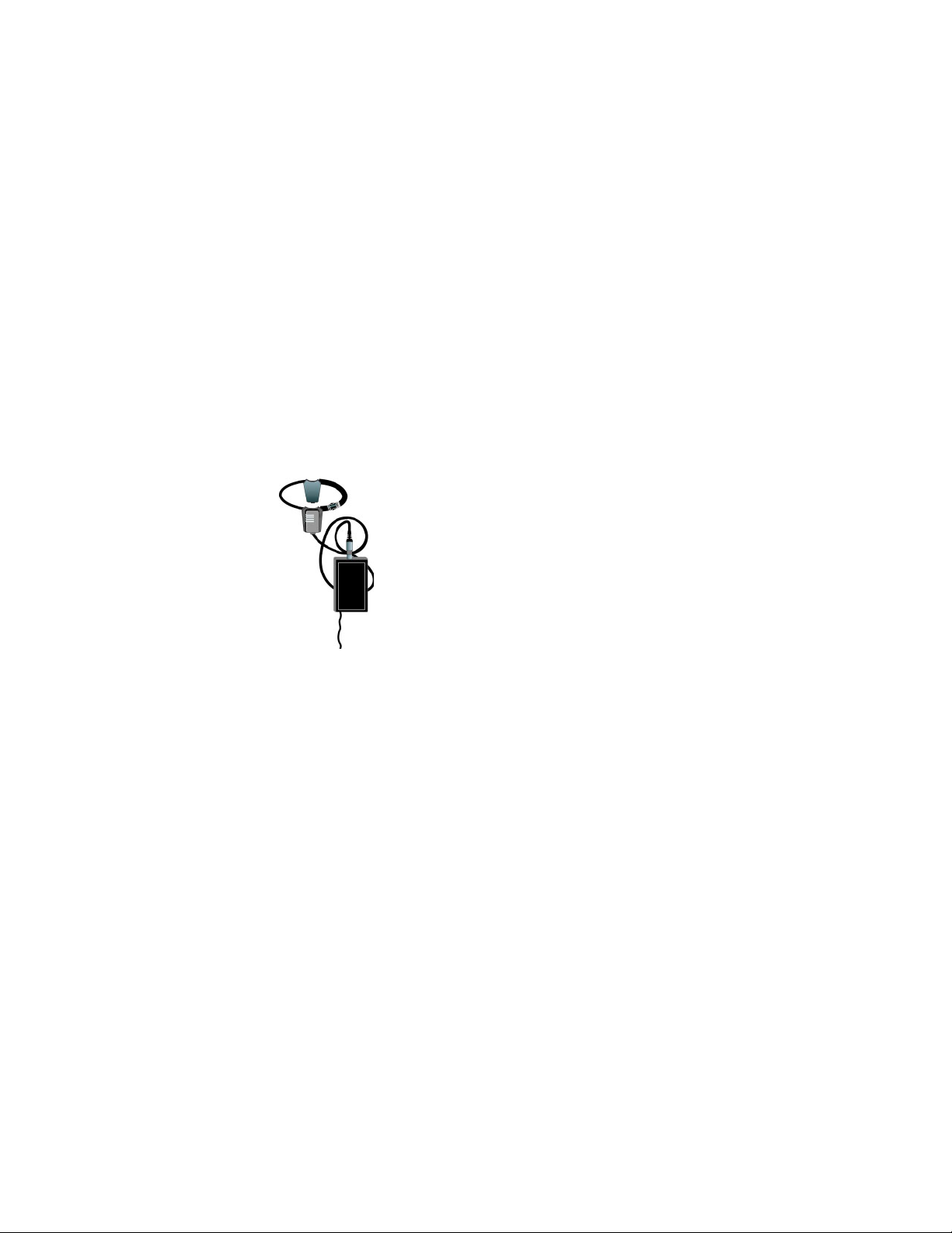
Includes a Tracking Ring Package (Figure 1), 3-CCD RF Tracking Keypad,
and Main Docking Station.
Figure 1. Tracking Ring Package
FIGURE 1.1 Tracking Ring Package
Recommended Accessories
SHOT Director
Some applications require precise and flexible camera control. The Grass
Valley DIGITAL SHOT Director is a joystick controller designed to give
ultimate control by affording the ability to adjust to the pan, tilt, zoom,
focus, iris, CCU functions and location presets on 1 to 16 different cameras
from one location. And its built-in CCU functionality allows adjustment of
each camera’s on-screen image.
8 CameraMan Installation and Operation Manual
Page 9

3-CCD DIGITAL Camera Components
Figure 2. JSC-2000D Digital SHOT Director
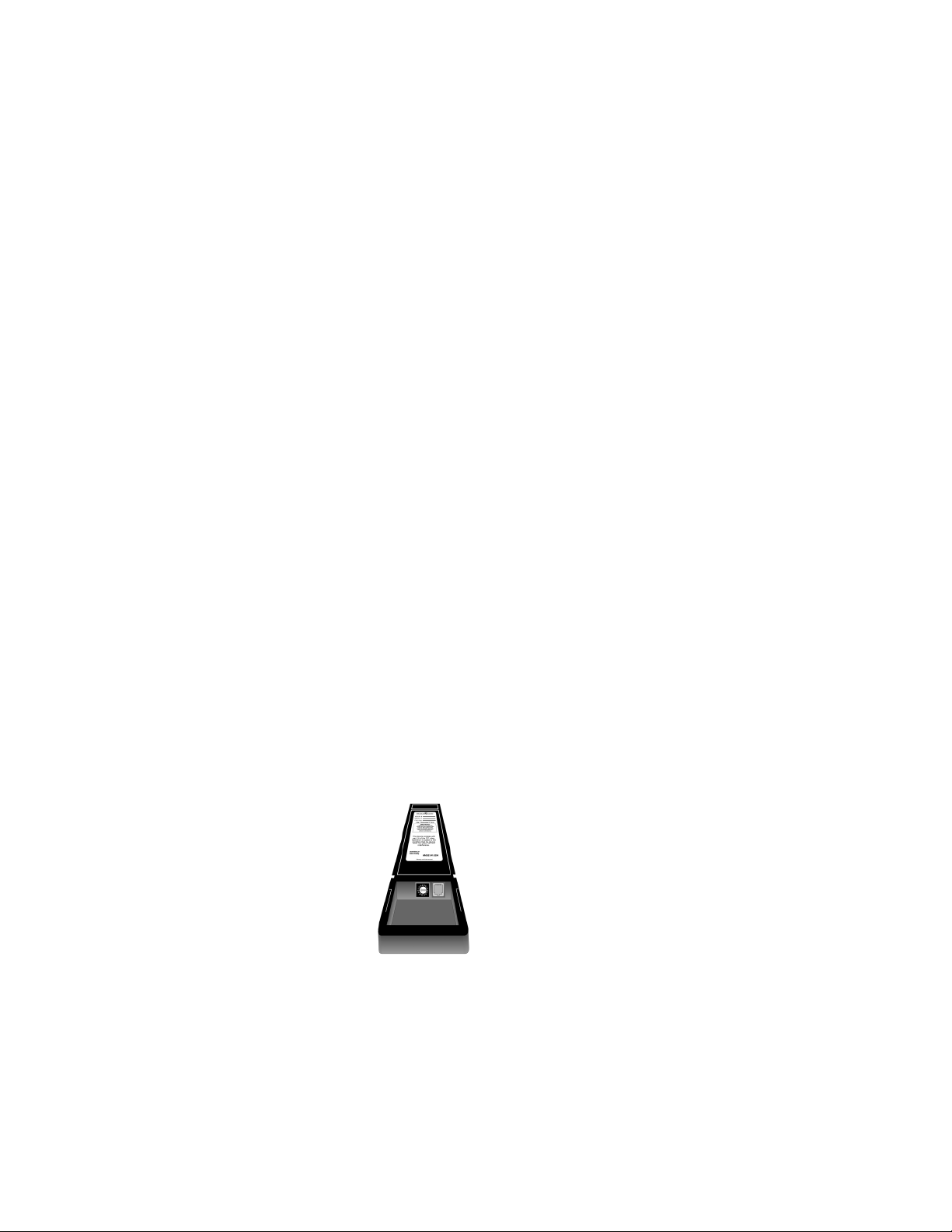
For a visual indication of which camera is selected in a multi-camera application, the CameraMan Tally Light (Figure 3) provides a high intensity
indication from an easy-to-install interface on the rear of the camera. A
bright red indicator is mounted to the top of a flexible pedestal, allowing
precise adjustment and positioning of the light for the best possible studiowide observation. Control of the Tally Light can be accomplished through
Control Center, and STUDIO, as well as via an external closure connected
to a side-mounted Phoenix connector. All current 3-CCD cameras are TallyLight compatible, and previous models are factory upgradable.
Figure 3. CameraMan Tally Light
SCRIPT Viewer Display
Adding a full-feature teleprompting display that moves with the camera is
now available with the addition of the powerful SCRIPT Viewer™. The 15”
active matrix, full color display is available separately and is easily
mounted to the camera. Contact your reseller for more information on the
complete Script Viewer system.
3-CCD DIGITAL Camera Components
Following is a description of each part that came with the CameraMan
CPT-2018 3-CCD DIGITAL Camera.
CameraMan Installation and Operation Manual 9
Page 10
Section 1 — General
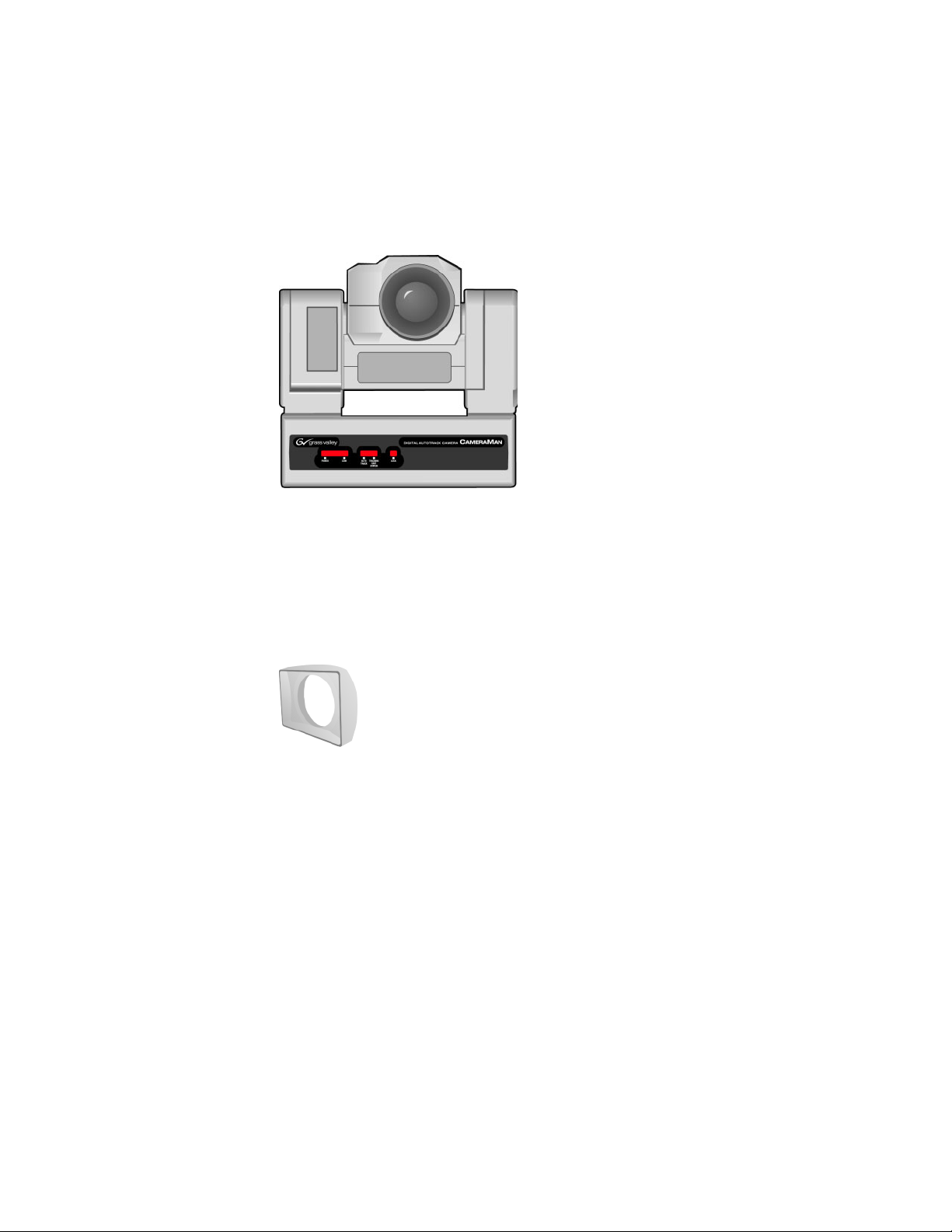
CameraMan 3-CCD DIGITAL Camera
The camera and its integrated intelligent pan/tilt system is the primary
component, and the basis for all of Grass Valley’s CameraMan camera systems.
Figure 4. Front of Camera
Lens Shroud
The 20x version of the 3-CCD DIGITAL Camera includes a rectangular lens
shroud (Figure 5).
Figure 5. Lens Shroud
Camera Control Block
The camera control block should be attached to the back of the camera. This
box is the point of connection for all RS-232 and RS-485. The only time this
box needs to be removed is if the camera is upgraded to a Presenter Camera
System.
Note If a Presenter or Deluxe Camera System was purchased, the camera control
block is not needed.
10 CameraMan Installation and Operation Manual
Page 11
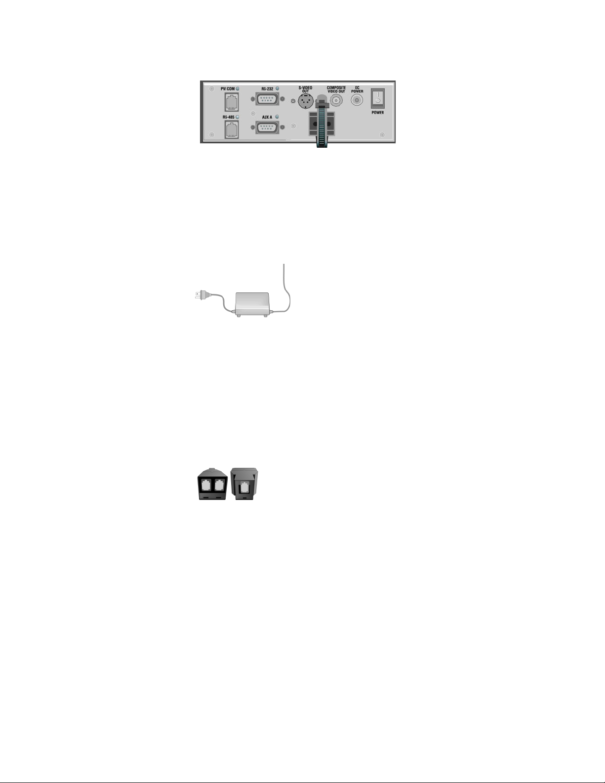
Figure 6. Camera Control Block
CameraMan Power Supply
The included power supply enables use with 50/60 Hz, 100-240V Power
sources.
Figure 7. CameraMan Power Supply
CameraMan Ports and Jacks
Connection Accessories
• RS-485 T Connector (Figure 8)
• 3’ CameraMan Communication Cable
• 25’ CameraMan Keypad Cable
Figure 8. T Connector
CameraMan Ports and Jacks
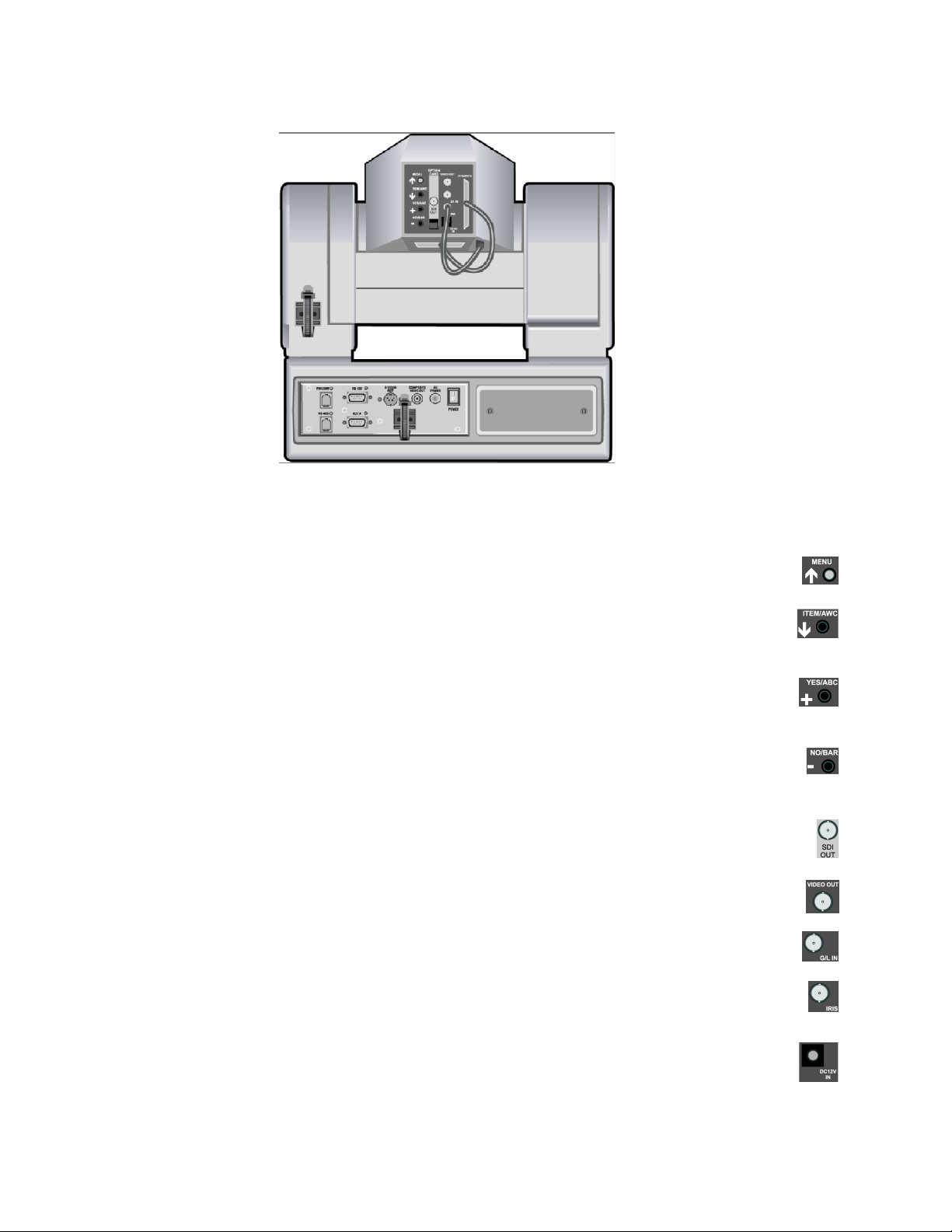
The back of the CameraMan CPT 200D 3-CCD DIGITAL Camera (Figure 9)
has a variety of ports and jacks used to connect the camera to other video,
audio, and camera control components in a system.
CameraMan Installation and Operation Manual 11
Page 12
Section 1 — General
Figure 9. Back of Camera
Back of Camera Block Overview
• Turns on the on-screen menu for appearance adjustments. Also
used to scroll upward through the on-screen menus.
When in shooting mode, the automatic white balance control can be set with
•
this switch. It can also be used to scroll downward through the on-screen
menus.
• When in shooting mode, the automatic black balance control can be set with
this switch. It is also used to display and increase the value of the sub-menus
of the main on-screen menu.
• When in shooting mode, the color bar and the shooting conditions are alter-
nately indicated by pressing this switch. This is also used to scroll downward
through, or lower the value of sub-menu items.
• A digital video signal is provided at this BNC connector.
• This is an ANALOG Video Out signal which is utilized to view the on-screen
menus.
• A GEN LOCK BNC connector used to synchronize the camera by connecting it
to the network’s Video Timing Source.
• Input terminal for lens iris control.
• Not Used.
12 CameraMan Installation and Operation Manual
Page 13
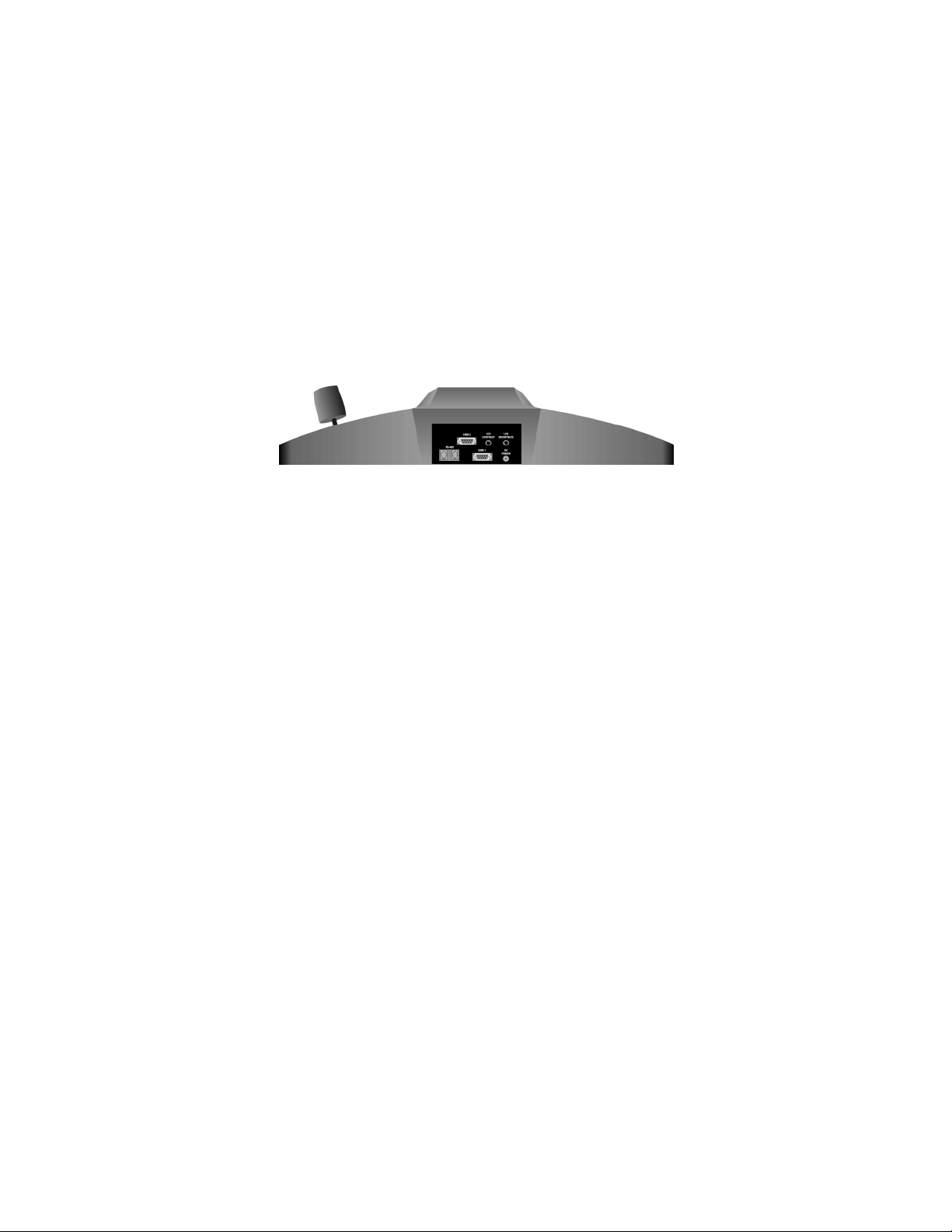
• Allows communication with the pan/tilt unit.
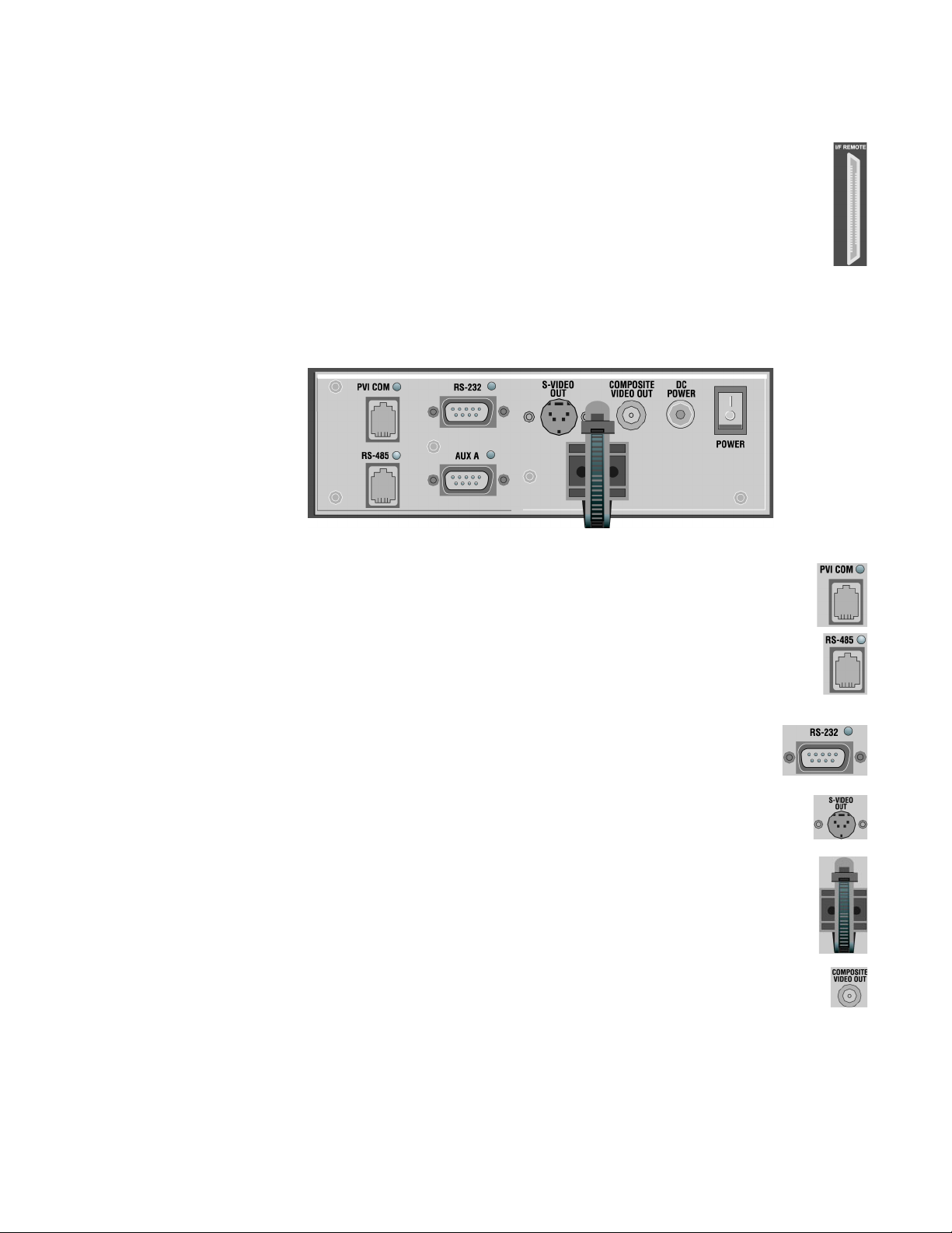
Camera Control Block Overview
Interface connections are located on the back of the camera control block
(Figure 10).
Figure 10. Camera Control Block
CameraMan Ports and Jacks
• Used by certain Grass Valley devices as a communication interface to the
camera system. (For example, a hard-wired keypad would attach here). This
is a standard 6-conductor RJ-11 jack.
• Used for RS-485 communications between the camera system and other
Grass Valley devices. This jack can be used to network multiple cameras or to
connect appropriate Grass Valley approved peripherals using a Grass Valley
T-connector. This is a standard 4-position modular handset jack.
• Provides RS-232 communications to external devices such as PC’s or
other vendor control systems. This connector is a standard DB-9
(female) connector.
• Non-functional
• Helps keep cables from becoming disconnected, or hindering the pan and
tilt capabilities of the camera.
• Non-functional
CameraMan Installation and Operation Manual 13
Page 14
Section 1 — General
• Power input for the CameraMan Camera. Plug only a Grass Valley power
supply (supplied) into this jack. No other types of power supplies should be
used.
• Used to power on/off the CameraMan Camera.
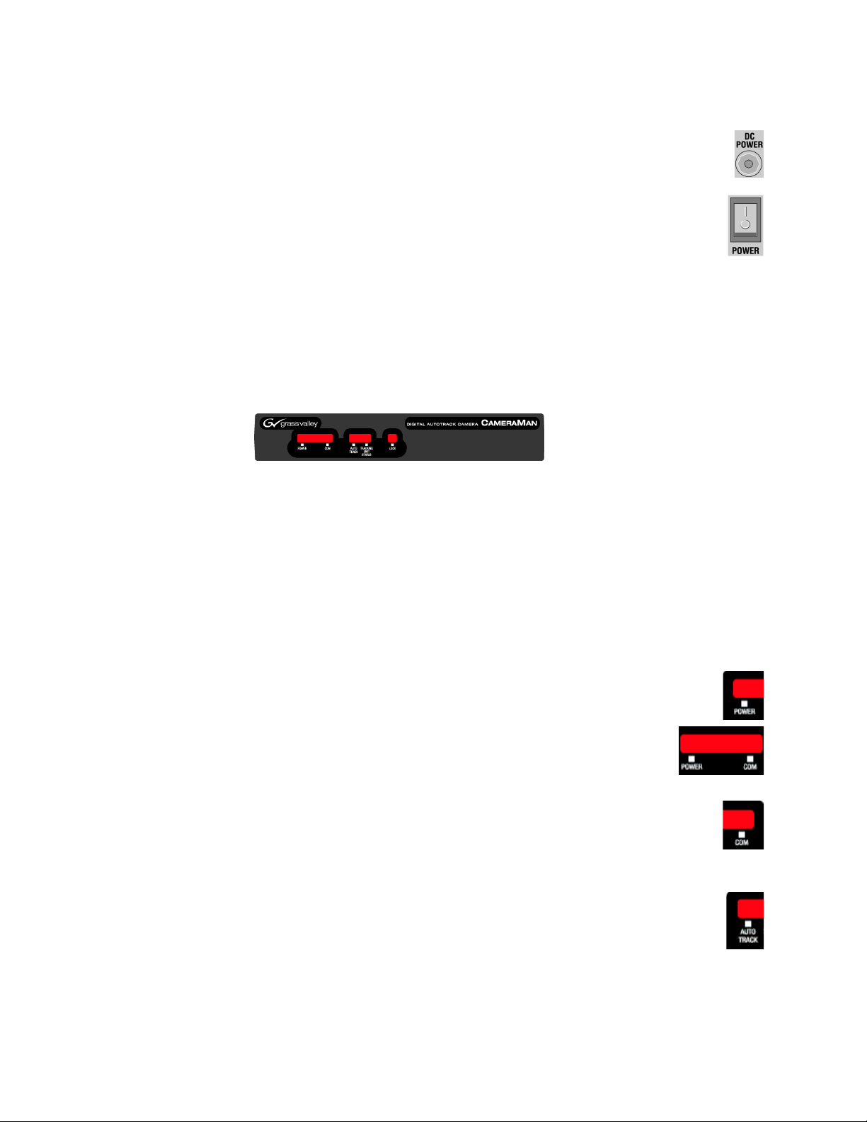
CameraMan LED Displays
On the front of the CameraMan CPT 2018 3-CCD Camera, there are several
LEDs (Figure 11). These indicate various functions that are being performed by the camera.
Figure 11. CameraMan LEDs
When the camera is first powered ON, all LEDs will illuminate. During this
time, basic system hardware checks are being performed. These checks
include communication with the camera interface board which verifies
proper installation of the camera block on the pan/tilt unit. After the initial
system checks are completed, the LEDs will turn on and off one by one in
a binary pattern. This pattern represents the progress the camera is making
during hardware initialization. During this initialization, pan/tilt positions
and camera settings are being restored. Once initialization is complete, the
camera LEDs will represent the following functions:
•
Indicates that the camera has an active power supply and is powered ON.
• (Between the Power and COM LEDs) The camera is in the camera
setup mode.
• Indicates that the camera is receiving valid network data on a communication
link (the LEDs on the back of the camera only indicate line activity, not valid
data).
• Indicates that the camera is in autoTRACK mode. The IR spinners are running
and the camera is attempting to acquire data from the TRP.
14 CameraMan Installation and Operation Manual
Page 15
• Indicates that the camera has acquired the RF signal from the TRP and is
receiving valid data. When this LED is OFF, TRP power is usually OFF.
• Reserved for future use.
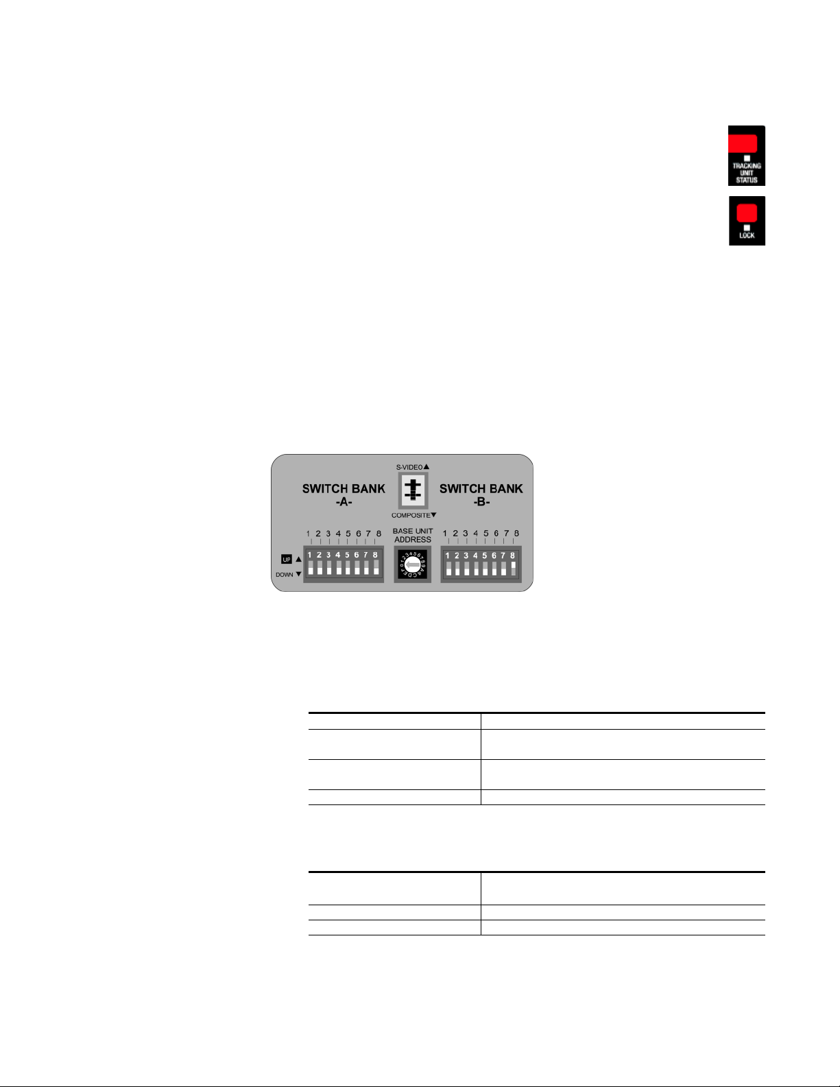
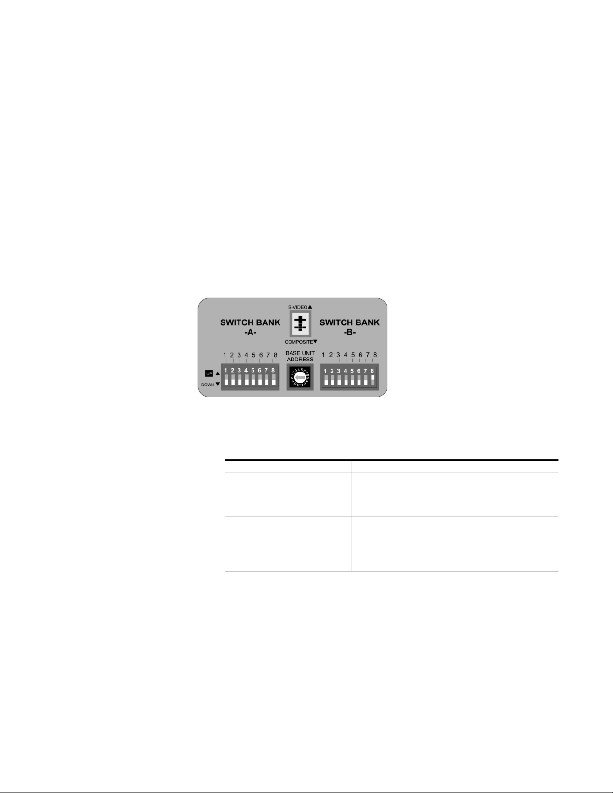
CameraMan Configuration Panel
Behind the configuration plate on the lower right side rear of the 3-CCD
DIGITAL Camera is the configuration panel (). These DIP and rotary
switches are used to link the camera’s settings to other components in the
system.
Figure 12. Configuration Panel
CameraMan Configuration Panel
Note After changing any switch’s settings, turn the camera off, then back on to
activate the change.
Switch Bank A
Switch 7 (Baud Rate
Switch)
Switch 8 (Memory Lock
Select Switch)
Switches 1, 2, 3, 4, 5 and 6 Reserved for future use.
Center Control
Switches
Video Select Switch Non-functional
Base Unit Address Used to configure the address of the Camera.
Used to change the camera’s Baud Rate.
Can be used to prevent programmed settings
from being accidentally overridden.
CameraMan Installation and Operation Manual 15
Page 16

Section 1 — General
Switch Bank B
Switch 1 (Protocol Select
Switch)
Switch 4 (RF Commands
Switch)
Switch 5 (Preset Save) Used to determine how the preset settings will be
Switch 8 (Interlink Switch) Used to disable commands from being sent on
Switches 2, 3, 6 and 7 Reserved for future use.
Tally Light Interface Port
The Tally Light Interface Port (Figure 13) provides output and external
control for CameraMan Tally Light.
Used to select the type of Protocol being used for
RS-232 and RS-485 communications. This can
be configured as either Basic or High Reliability.
Used to enable or disable the RF Receiver in the
CameraMan camera.
saved.
the RS-485 bus to other CameraMan devices.
Figure 13. Tally Light Interface Port
16 CameraMan Installation and Operation Manual
Page 17
Mounting the Camera
Mount the DIGITAL Camera on any flat, non-slick, non-metal surface with
a minimum supporting area of 8” x 8” by following these easy steps.
1. Check the selected camera location to ensure that there is enough
camera and cable clearance space (Figure 14) for the CameraMan to pan
and tilt without obstruction.
Note Do not mount the camera upside down, or with more than a 10o angle from
the horizontal.
Note To assist in placing the CameraMan to achieve optimum optical views, see the
respective appendix in this manual.
Figure 14. Clearance Diagram
Section 2
2. Locate the zero-degree position mark labeled FRONT on the bottom of
the base unit. This mark helps ensure that the base unit is calibrated
correctly. Point this indicator mark in the direction that best reflects the
center of travel in which the camera will be used (usually the center of
the room).
3. To ensure that the camera-mounting is not prone to vibrations, securely
fasten the camera to a rigid flat surface using a 1/4”-20 UNC cap screw
that does not extend into the base platform by more than 0.4”. (The
screw hole is provided in the base platform for this purpose. The cap
screw is not provided.) This screw should be hand-tightened. If
necessary, use a non-hardening threadlock to prevent the screw from
loosening.
Note Be sure to take environmental conditions into consideration when operating
the camera. Always operate the camera indoors, and follow the temperature
and humidity specifications.
CameraMan Installation and Operation Manual 17
Page 18
Section 2 — Mounting the Camera
Connecting the Camera System
Follow the instructions below to begin connecting the camera to the
system.
Note After connecting each cable to the camera, let it hang loosely behind the
Connecting Camera Control Cables
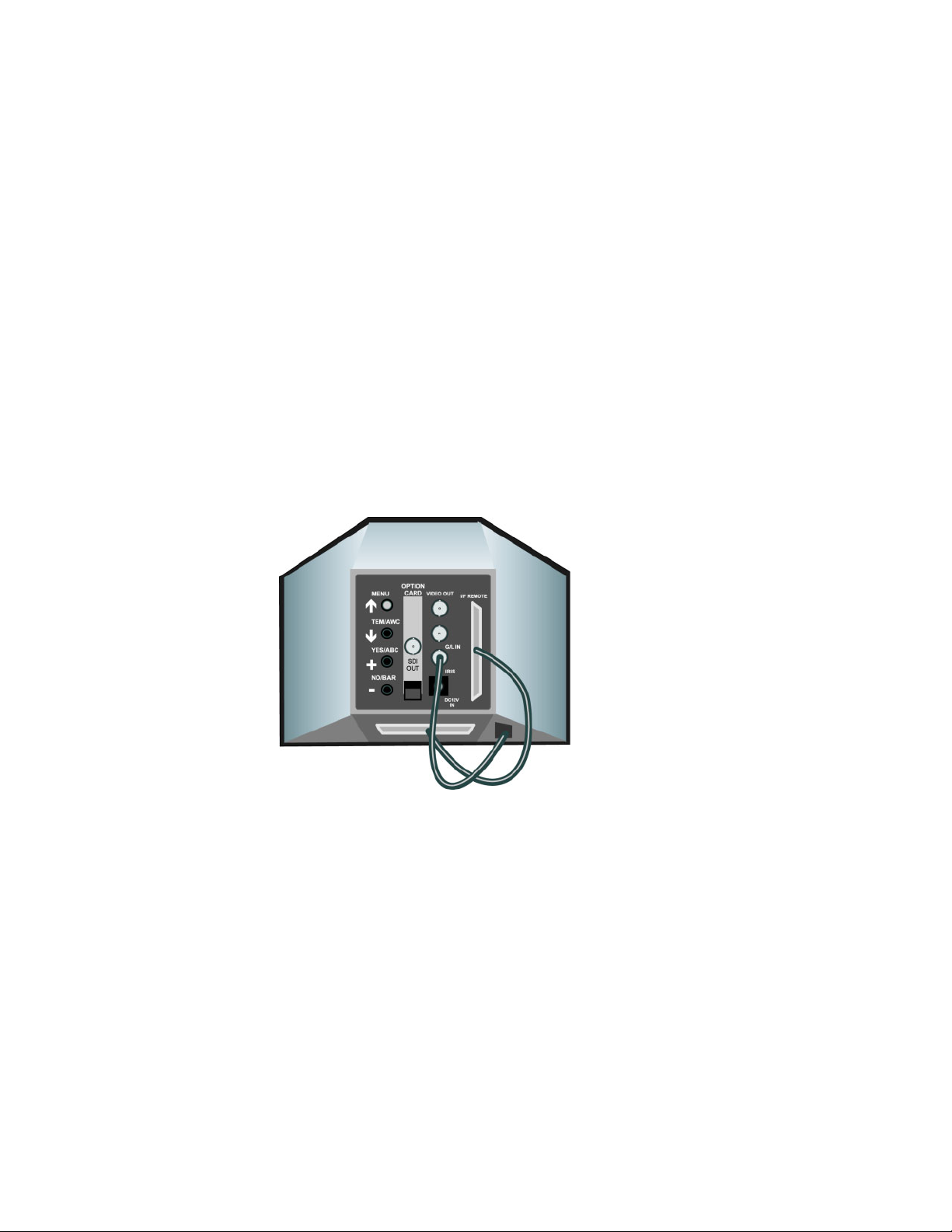
• On the back of the camera block (Figure 15), there are two cables. These
provide the camera lens, power, and video signals. The cables must be
attached for the camera to operate properly.
• Connect the 12-pin connector to the IRIS jack.
• Connect the 50-pin SCSI connector to the I/F REMOTE jack.
Figure 15. Back of Camera Block
camera. Then follow the instructions in Cable Restraint on page 21 before
attaching the other ends of the cable to other equipment. This relieves undue
stress on the cables and allows the camera to move freely.
Connecting the SDI Video Output
The 3-CCD DIGITAL Camera supports SDI format (270 Mbls component
out).
Connect to the BNC jack labeled SDI OUT on the back of the camera
shroud, using a standard SDI coaxial cable with a BNC connector.
Connecting to the RS-232 Port
The 3-CCD DIGITAL Camera provides for RS-232 communications using
the DB-9 jack on the back of the camera, labeled RS-232. This RS-232 port
can be used to control the CameraMan Camera from external devices such
as a PC or other vendor control system (i.e.: AMX, Crestron). Connect to
18 CameraMan Installation and Operation Manual
Page 19
this port using a standard computer cable with a DB-9 connector. When
used with a DIGITAL SHOT Director, this port operates at 19,200 Baud, No
Parity and software hand-shaking using Grass Valley High Reliability protocol. Otherwise, the port operates at 9600 Baud, No Parity, and software
handshaking using Grass Valley High Reliability or Basic protocols.
Note To verify the protocol is being used, check the PROTOCOL switch on the con-
figuration panel on the back lower-right of the DIGITAL Camera.
Note The COM light above the RS-232 port is used to indicate communication
activity.
Connecting Camera Control Devices
There are several ways to control the CameraMan’s movement. The following information explains how to connect and configure the included
Camera Control Keypad, or the optional DIGITAL SHOT Director.
Note Do not use the Camera Control Keypad and the CameraMan SHOT Director at
the same time.
Camera Control Keypad (or Tracking System Keypad)
The included Camera Control Keypad controls the camera’s movement via
wireless RF technology (up to 60 feet) or hard-wired connection (up to 250
feet). If you choose to use a Camera Control Keypad in the hard-wired
mode, follow these directions for installation.
1. Using the 25’ CameraMan Keypad Cable included with your camera,
connect one end of the cable to the RJ-11 type jack located in the battery
compartment (Figure 16) of the keypad.
Figure 16. Keypad Battery Compartment
2. Connect the other end of the cable to the RJ-11 type jack on the camera
control block, labeled PVI COM.
Note When the system is powered on, the light on the keypad should illuminate
momentarily, indicating the keypad is ready for operation. The light located
above the PVI COM port is used to indicate communication activity.
CameraMan Installation and Operation Manual 19
Page 20
Section 2 — Mounting the Camera
Note Using cable other than Grass Valley supplied cable for the PVI COM port may
DIGITAL SHOT Director
The optional DIGITAL SHOT Director multi-camera controller can be connected in hard-wired mode only. Follow these directions to connect the
DIGITAL SHOT Director to the CameraMan.
1. Using a standard RS-485 cable, connect one end of the cable to one of
the RS-485 jacks (either one) on the back of the Shot Director.
Figure 17. Back of SHOT Director
2. Connect the other end of the cable to:
cause damage.
• The jack labeled RS-485 on the camera control block for single camera
applications, or
• The T-Connector for multiple-camera applications. Then use the provided 3’ CameraMan Communication Cable to connect the T-connector
to the camera’s RS-485 jack.
Note If using a Camera Control Keypad or DIGITAL SHOT Director, refer to the
respective operation manual. If it is unavailable, contact your local reseller or
Grass Valley.
Cable Restraint and System Power
Notice that, if left alone, the connected cables may impede camera movement. To prevent this, the 3-CCD DIGITAL Camera comes equipped with
two cable restrainers—one on the left back and one on the camera control
block. See Figure 18. Follow the instructions below to properly restrain the
cables and power-up the camera.
20 CameraMan Installation and Operation Manual
Page 21
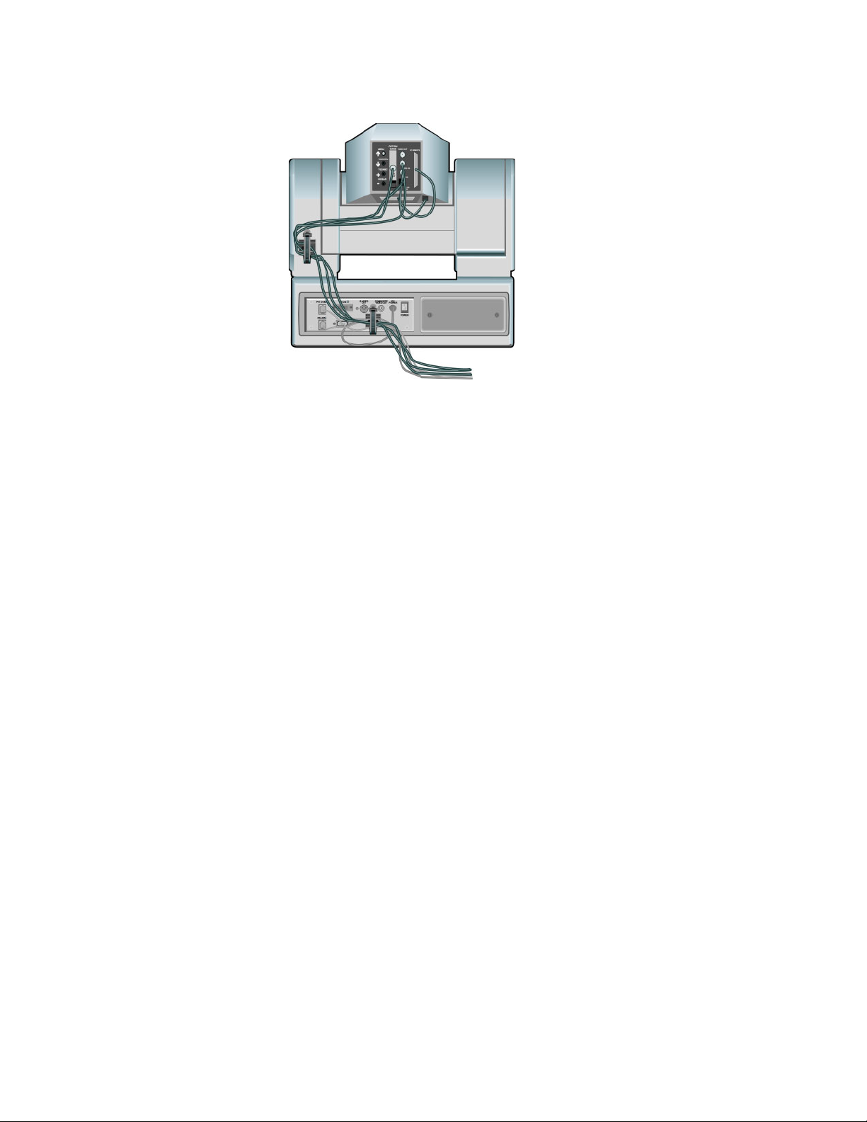
Figure 18. Camera Cable Restraint
Cable Restraint
Cable Restraint and System Power
For upper (i.e. GEN LOCK) cable connections (if used)
1. Locate the cable restraint on the back left side of the camera.
2. Insert cable(s) through the cable restraint from left to right.
Note Allow 16” of cable between the restraint and the connection port to provide
enough slack for the camera’s tilting movement.
3. Tighten the restraint by pulling on the strap’s “free” end to prevent any
cable from becoming dislodged. (The cable restraint is reusable and
adjustable).
4. Group the cables with all the other cables connected to the connector
box and follow the instructions below to feed them through the lower
cable restraint.
For lower cable connections
1. Insert all cables (upper and lower) through the cable restraint from left
to right. This will result in the cables being located approximately in the
center of the camera, instead of near the edge.
2. Tighten the restraint by pulling on the strap’s “free” end to prevent any
cable from becoming dislodged.
Note To relieve undue stress on the camera and the cable connections, it is impor-
tant to fasten all cables using the cable restrainer on the back of the camera.
Note Be sure to leave enough slack in the cables for the camera to pan left and right
free of any constraints.
CameraMan Installation and Operation Manual 21
Page 22

Section 2 — Mounting the Camera
Power Supply Connection
Mount the Power Supply with any orientation, or on top of a table or rollabout unit by using the following steps.
1. Verify that the POWER switch, on the back of the camera, is turned OFF.
2. Plug the 5.5mm power supply cord connector into the DC POWER jack
on the back of the camera.
3. Connect the other end of the power supply to a 120/240 V ac power
source.
22 CameraMan Installation and Operation Manual
Page 23
Switch Configuration
Once connected to the power supply and control devices, the DIGITAL
Camera must be configured to work in the desired application. To begin,
remove the configuration plate on the back right side of the camera by
removing the two screws holding it in place. Behind it are the configuration
switches (Figure 19).
Figure 19. Configuration Switches
Section 3
Note All switches not discussed in this section should remain in the DOWN or OFF
position.
Switch Bank A
Dip Switch 7 (Baud Rate) Used to configure camera Baud Rate for the RS-
232 and RS-485 ports. Set the switch in the UP
position for 19,200 baud and the DOWN position
for 9600 baud. (The factory default is UP.)
Dip Switch 8 (Memory) For the majority of applications, this switch should
be set to the UP (UNLOCK) position. When in the
DOWN (LOCK) position, all programmed features
are locked and cannot be overridden. (The
factory default is UP.)
CameraMan Installation and Operation Manual 23
Page 24

Section 3 — Switch Configuration
Central Control
Switches
Base Unit Address Use the 16-position rotary switch labeled BASE
UNIT ADDRESS to set the unique identification
number for the specific CameraMan camera. If
using the optional Keypad, DIGITAL SHOT
Director, or another control system, refer to the
documentation provided with those accessories
for proper configuration.
Switch Bank B
Dip Switch 1 (Protocol) Selects the communication protocol to be used
by the RS-232 and RS-485 ports on the camera.
The High Reliability protocol includes some
advanced error checking that is not performed in
the Basic protocol. (The factory default is
DOWN.)
Dip Switch 4 (RF
Command)
In the DOWN position, the camera responds to
commands sent from an RF Keypad. In the UP
position, the RF receiver in the camera is
disabled and the camera cannot receive
commands directly from a wireless keypad. (The
factory default is DOWN.)
Note When using multiple cameras networked on the RS-485 bus, only one
camera should have its RF receiver enabled. Set switch 4 on the other
cameras to UP.
Dip Switch 5 (Preset Save) Determines how the preset settings are recalled.
DOWN recalls Manual Gain, Iris, and Focus
settings. UP recalls only the Auto settings for
presets and autoTRACK Views. (The factory
default is DOWN.)
Dip Switch 8 (Interlink) Use this feature in multi-camera applications.
When it is in the DOWN position, all commands
are passed onto the RS-485 communication bus
to the appropriate camera. For a single-camera
application, this switch setting does not matter.
(The factory default is DOWN.)
24 CameraMan Installation and Operation Manual
Page 25

System Startup
Note Before powering the CameraMan system, ensure all necessary connections
and configurations are complete
1. Just switch the Power button on the back of the CameraMan DIGITAL
Camera to the ON position. The Camera should automatically enter its
position calibration mode and then stop at the zero degree point.
2. Verify that the camera is now facing in the direction the “FRONT” label
was pointing during mounting.
3. If you are using the Camera Control Keypad or DIGITAL SHOT
Director, make sure its base unit address is the same as on the camera.
If they are, verify that the camera’s PAN and TILT functions are
working properly.
Section 4
CameraMan Installation and Operation Manual 25
Page 26

Section 4 — System Startup
26 CameraMan Installation and Operation Manual
Page 27

Troubleshooting
Should any problems occur with the CameraMan CPT 2018 3-CCD
DIGITAL Camera, please refer to the following guide. If questions or problems still exist after troubleshooting, please contact your authorized Grass
Valley reseller or contact Grass Valley Customer Support directly.
Problem
The Camera’s Video is not working properly.
Solution
1. Verify that the SDI OUT connection is being used on the back of the
camera shroud.
2. Verify that the video output of the camera is connected to the
appropriate video input on the switcher or CODEC.
Problem
Appendix A
No communications through the RS-232 port.
Solution
1. Verify that the cable being used is wired correctly.
2. Verify that the PROTOCOL SELECT switch on the rear configuration
panel is set properly.
3. Verify that the BASE UNIT ADDRESS on the rear configuration panel
is set properly.
4. Does the COM light above the RS-232 port on the back of the camera
blink when you send a command through this port? If no, change the
cable and retry.
5. Verify that the POWER LED, on the front of the camera, is illuminated.
Also verify that the 12VDC indicator, on the rear of the camera block, is
illuminated. If the POWER LED is not lit, check the POWER switch to
make sure that it is ON, then verify that the Power Supply is connected
to the camera properly. If the 12VDC LED on the rear of the camera
block is not illuminated, verify that the I/F Remote SCSI cable is
connected properly.
CameraMan Installation and Operation Manual 27
Page 28

Appendix A — Troubleshooting
28 CameraMan Installation and Operation Manual
Page 29

Appendix B
Multi-Camera Applications
Note If the camera does not move, refer to the TROUBLESHOOTING section of the
Camera Control Keypad, or DIGITAL SHOT Director manual.
Note If using more than one CameraMan 3-CCD DIGITAL Camera, the cameras
need to be set up in a “daisy-chain” network configuration using the following
steps:
1. Connect cameras together by plugging the Grass Valley T-connector
into the RS-485 port on the back of the camera.
2. Connect each camera using a 4-conductor cable, with 4-position
modular handset plugs wired straight-through:
•Pin 1 to Pin 1
•Pin 2 to Pin 2
•Pin 3 to Pin 3
•Pin 4 to Pin 4
Note Do NOT use a pre-wired standard phone cable. The wiring is different and
may cause damage.
3. Using the BASE UNIT ADDRESS rotary switch located on the back of
the Camera, configure each camera with a unique Base Unit Address;
i.e. Camera One set with address 0, Camera Two set with address 1, and
so on.
4. To control each camera with your Camera Control Keypad, the rotary
switch inside the keypad battery compartment must match the lowest
Base Unit Address in your system.
CameraMan Installation and Operation Manual 29
Page 30

Appendix B — Multi-Camera Applications
30 CameraMan Installation and Operation Manual
Page 31

Camera Specifications
This device complies with part 15 of the FCC rules. Operation is subject to
the condition that this device does not cause harmful interference. FCC
identifier: JFECM003-AA
Note In the following specifications the CPT 2018-A3D is shown without brackets
and the CPT 2018 A3DP is shown in brackets.
Image Elements 1/2” IT type 3-CCD
Pixels Total Elements: Approx. 410,000 [470,000]
Effective Elements: Approx. 380,000 [440,000]
Imaging Area 6.4 H x 4.8 V (equivalent to 1/2”)
Scanning System 2:1 interlaced NTSC system
[2:1 interlaced PAL system]
Scanning Frequency Horizontal = 15.734kHz [15.625kHz]
Vertical = 59.94Hz [50Hz]
Lens Mount 1/2” Bayonet Mount
Synchronize System Internal/external synchronization
Standard Illumination 2000 Ix, F14
Minimum Illumination 0.005 Ix (F1.4) 0.00005 Ix (F1.4) (2 sec. CCD
accumulation)
Signal-to-Noise Ratio 67 dB (DNR on) [65 dB (DNR on)]
Horizontal Resolution 850 lines
Registration 0.05%
Image Enhancer Horizontal/vertical
White Balance A/B 2 memory AWC, ATW
Black Balance Self-adjusting
Color Bar SMPTE color bar (setup 0/7.5 IRE)
[EBU color bar]
Shutter Speed OFF, 1/100 [1/120], 1/250, 1/500, 1/1000, 1/2000,
1/4000, 1/10000 Synchro-scan ELC
Gain Manual: max. 72dB (0~30 dB in steps, Night Eye/H,
Digital Gain 0~30 dB in 6 dB steps)
Appendix C
Auto: max. 42dB (AGC 0~30 dB, Night Eye/H)
Iris Auto (Manual by RCU control)
Video Output Composite: 1 Vp-p/75 ohm (BNC, 50P connector)
YC: Y 1Vp-p, C 0.286Vp-p [0.3Vp-p] (50P connector)
Component: Y 1.0Vp-p, Pr/Pb 0.7Vp-p, RGB 0.7Vp-p/
75 ohm (50P connector)
Operating
Temperature
o
F~113oF (-10oC~+45oC)
14
CameraMan Installation and Operation Manual 31
Page 32

Appendix C — Camera Specifications
Image Elements 2/3” IT type 3-CCD
Pixels Total Elements: Approx. 510,000 [595,728]
Imaging Area 8.8H X 6.6V (mm) (2/3” 4:3)
Scanning System 2:1 interlaced NTSC system
Scanning Frequency Horizontal = 15.734 kHz [15.625 kHz]
Lens Mount 2/3” Bayonet Mount
Synchronize System Internal/external synchronization
Standard Illumination 2000 Ix, F11
Minimum Illumination 0.4 Ix (F1.7, Night Eye H)
Signal-to-Noise Ratio 65 dB (DNR on) [63 (DNR on)]
Horizontal Resolution 850 lines
Registration 0.05%
Image Enhancer Horizontal/vertical
White Balance A/B 2 memory AWC,ATW
Black Balance Self-adjusting
Color Bar SMPTE color bar (setup 0/7.5IRE)
Shutter Speed OFF, 1/100 [1/120], 1/250, 1/500, 1/1000, 1/2000, 1/
Gain Manual: max. 42 dB (0~30 dB in steps, Night Eye H/L)
Effective Elements: Approx. 460,000 [538,200]
9.6H X 5.4V (mm) (2/3” 16:9)
[2:1 interlaced PAL system]
Vertical = 59.94 Hz [50 Hz]
[EBU color bar]
4000, 1/10000 Synchro-scan ELC
Auto: max. 42 dB (AGC 0~30 dB, Night Eye/H)
Iris Auto (Manual by RCU control)
Video Output Composite: 1 Vp-p/75 ohms (BNC, 50P connector)
YC: Y 1 Vp-p, C 0.286 Vp-p [0.3 Vp-p] (50P connector)
Component: Y 1.0 Vp-p, Pr/Pb 0.7 Vp-p, RGB 0.7 Vp-p/
75 ohms (50P connector)
Operating
Temperature
o
F~113oF (-10oC~+45oC)
14
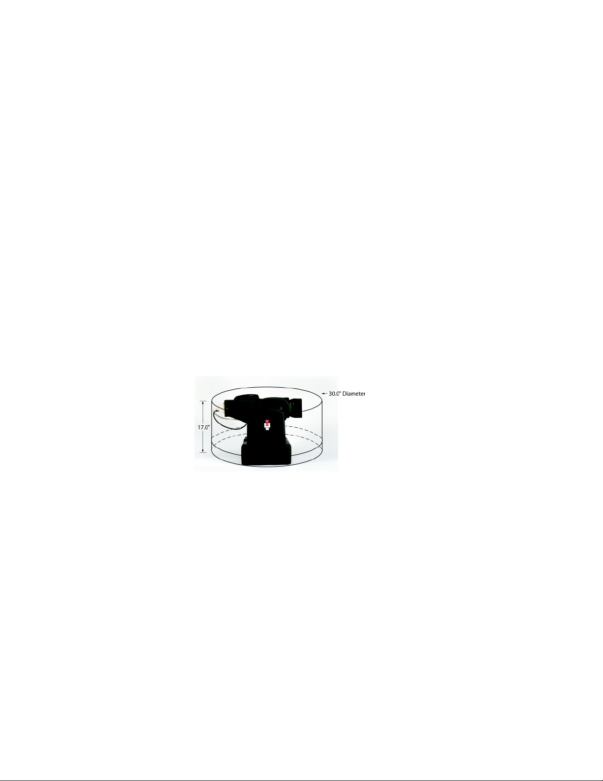
CameraMan Clearance
The minimum dimension for the CameraMan is a circular diameter of 30”.
This accounts for both camera and cable clearance. Check cable movement
to avoid binding and stress on the camera.
32 CameraMan Installation and Operation Manual
Page 33

Pin-Out Diagrams
Following are the pinout connections on the rear of the CameraMan camera
control block. Diagrams are for reference.
PVI COM RJ-11
Connector Pin Signal
112v
212v
3Ground
4Signal A
5Signal B
6Ground
Appendix D
RS-485 Four Position Modular Handset
Connector Pin Signal
1Ground
2Signal A
3Signal B
4Ground
RS-232 9-pin D-9
Connector Pin Signal
2Transmit
3 Receive
5Ground
1,4,6-9 Not Used
CameraMan Installation and Operation Manual 33
Page 34

Appendix D — Pin-Out Diagrams
5.5 mm dc Power Connector
Connector Pin Signal
1+ 18v DC
2Ground
34 CameraMan Installation and Operation Manual
Page 35

Appendix E
Field-Of-View Specifications
The following reference charts represent the approximate size of the field
of view and angle of view from various distances and with different lenses.
20 x 6.4 Lens on Standard 4:3 DIGITAL Camera.
Dist. from Lens No Zoom Full Zoom
2
Hor. (ft) Vert. (ft) ft2
(feet) Hor. (ft) Vert. (ft) ft
10 9.78 7.50 73.39 0.50 0.38 0.19
15 14.68 11.25 165.12 0.75 0.56 0.42
20 19.57 15.00 293.54 1.00 0.75 0.75
25 24.46 18.75 458.66 1.25 0.94 1.17
30 29.35 22.50 660.67 1.50 1.13 1.69
35 34.24 26.25 898.97 1.75 1.31 2.30
40 39.13 30.00 1174.16 2.00 1.50 3.00
45 44.03 33.75 1486.05 2.25 1.69 3.80
50 48.92 37.50 1834.62 2.50 1.88 4.70
55 53.81 41.26 2219.90 2.75 2.06 5.68
60 58.70 45.01 2641.86 3.00 2.25 6.76
65 63.59 48.76 3100.52 3.25 2.44 7.93
70 68.48 52.51 3595.86 3.50 2.63 9.20
o
Angle of View 53
08’ 41o 07’ 2o 52’ 2o 09’
CameraMan Installation and Operation Manual 35
Page 36

Appendix E — Field-Of-View Specifications
19 x 9 Lens on 16:/4:3 DIGITAL Camera switched to Aspect Ratio without crossover Adaptor.
Dist. from Lens No Zoom Full Zoom
(feet) Hor. (ft) Vert. (ft) ft
10 9.78 7.34 71.75 0.52 0.39 0.20
15 14.66 11.01 161.43 0.78 0.58 0.45
20 19.55 14.68 286.98 1.04 0.78 0.80
25 24.44 18.35 448.41 1.30 0.97 1.26
30 29.33 22.02 645.71 1.56 1.16 1.80
35 34.22 25.69 878.88 1.81 1.36 2.46
40 39.11 29.36 1147.93 2.07 1.55 3.21
45 43.99 33.02 1452.85 2.33 1.74 4.07
50 48.88 36.69 1793.64 2.59 1.94 5.02
55 53.77 40.36 2170.31 2.85 2.13 6.08
60 58.66 44.03 2582.84 3.11 2.33 7.23
65 63.55 47.70 3031.25 3.37 2.52 8.49
70 68.43 51.37 3515.54 3.63 2.71 9.84
Angle of View
52.1
2
Hor. (ft) Vert. (ft) ft2
o
40.3
o
2.97
2.22
o
Note To obtain the conventional 4:3 view, the user must use a crossover adapter
19 x 9 Lens on 16:/4:3 DIGITAL Camera switched to Aspect Ratio with
crossover Adaptor.
Dist. from Lens No Zoom Full Zoom
2
(feet) Hor. (ft) Vert. (ft) ft
10 8.00 6.00 48.00 0.42 0.31 0.13
15 12.00 9.00 108.00 0.63 0.47 0.30
20 16.00 12.00 192.00 0.84 0.63 0.53
25 20.00 15.00 299.99 1.05 0.79 0.82
30 24.00 18.00 431.99 1.26 0.94 1.18
35 28.00 21.00 587.99 1.47 1.10 1.61
40 32.00 24.00 767.98 1.68 1.26 2.11
45 36.00 27.00 971.98 1.89 1.41 2.67
50 40.00 30.00 1199.97 2.09 1.57 3.29
55 44.00 33.00 1451.97 2.30 1.73 3.98
60 48.00 36.00 1727.96 2.51 1.89 4.74
65 52.00 39.00 2027.95 2.72 2.04 5.56
70 56.00 42.00 2351.94 2.93 2.20 6.45
Angle of View
43.6
o
33.4
o
Note When the camera is switched to a 16:9 aspect ratio, the wide-angle conver-
sion is at approximately 11mm
Hor. (ft) Vert. (ft) ft2
2.4
o
1.8
o
36 CameraMan Installation and Operation Manual
Page 37

19 x 9 Lens on 16:/4:3 DIGITAL Camera switched to 16:9 Aspect Ratio.
Dist. from Lens No Zoom Full Zoom
2
(feet) Hor. (ft) Vert. (ft) ft
10 10.66 6.00 63.94 0.56 0.31 0.18
15 15.98 9.00 143.87 0.84 0.47 0.39
20 21.31 12.00 255.77 1.12 0.63 0.70
25 26.64 15.00 399.64 1.40 0.79 1.10
30 31.97 18.00 575.48 1.68 0.94 1.58
35 37.30 21.00 783.297 1.96 1.10 2.15
40 42.63 24.00 1023.08 2.23 1.26 2.81
45 47.95 27.00 1294.84 2.51 1.41 3.55
50 53.28 30.00 1598.56 2.79 1.57 4.39
55 58.61 33.00 1934.26 3.07 1.73 5.31
60 63.94 36.00 2301.93 3.35 1.89 6.32
65 69.27 39.00 2701.57 3.63 2.04 7.42
70 74.60 42.00 3133.19 3.91 2.20 8.60
Angle of View
56.1
o
33.4
o
Hor. (ft) Vert. (ft) ft2
3.2
o
1.8
o
CameraMan Installation and Operation Manual 37
Page 38

Appendix E — Field-Of-View Specifications
38 CameraMan Installation and Operation Manual
Page 39

The 20x Lens Shroud
The 20x version of the CameraMan 3-CCD DIGITAL Camera comes
equipped with a rectangular lens shroud (Figure 20). The shroud helps to
keep out glares from light sources located on the sides of the camera.
Figure 20. Lens Shroud
Appendix F
1. Locate the red dots on the top and bottom of the shroud, and on the lens
itself.
2. Align the red dot on the shroud with the dot on the lens, then slide the
shroud over the lens.
3. Tighten the shroud in place using the bolt attached to the shroud.
CameraMan Installation and Operation Manual 39
Page 40

Appendix F — The 20x Lens Shroud
40 CameraMan Installation and Operation Manual
Page 41

Appendix G
Typical CameraMan System Diagram
Below is a typical setup for the CameraMan camera system.
Note Items in the diagram are not to scale.
Figure 21. Typical Setup Diagram
CameraMan Installation and Operation Manual 41
Page 42

Appendix G — Typical CameraMan System Diagram
42 CameraMan Installation and Operation Manual
Page 43

Appendix H
CPT 2018-A3D On-Screen Menus
The 3-CCD DIGITAL Camera allows for adjustments to the camera settings
via on-screen menus by using the controls on the back of the camera block,
the Camera Control Keypad, or DIGITAL SHOT Director. These adjustments should be performed by qualified technical personnel only. If your
system includes a DIGITAL SHOT Director, always use the DIGITAL
SHOT Director’s LCD menus to make these adjustments.
Use Mode Setting
Setting by Camera
The camera has four use modes, and various functions for four use modes
have been preset. Functions can be set as best suited to each use mode.
•Halogen mode
• Suited to indoor shooting, such as at weddings, parties, lecture meetings, events, etc. Settings can be changed using a simple menu.
• Fluorescent mode
• Suited to indoor shooting under fluorescent lighting. Settings can be
changed using a simple menu.
•Outdoor mode
• Suited to outdoor shooting. Settings can be changed using a simple
menu.
• User mode
• Settings can be changed using a detail menu.
1. Turn the camera on while keeping the MENU switch (Figure 22)
depressed.
CameraMan Installation and Operation Manual 43
Page 44

Appendix H — CPT 2018-A3D On-Screen Menus
Figure 22. Camera Back Switches
2. The use mode setting menu (Figure 23) appears on the monitor screen
and one of the use modes blinks.
Figure 23. Use Mode Setting Menu
3. Press the MENU switch, ITEM/AWC switch, or NO/BAR switch to let
the desired use mode blink.
• MENU switch: The blinking item moves up one.
• ITEM/AWC switch, NO/BAR switch: The blinking item moves
down one.
4. Press the YES/ABC switch. The blinking use mode comes into effect.
After the use mode setting menu is shown for about 5 seconds, the
camera returns to be ready for operation. Then, the camera operates in
the selected use mode.
Note On-screen menu items can only be viewed by connecting to the analog VIDEO
OUT connector on the rear of the camera block.
44 CameraMan Installation and Operation Manual
Page 45

Menu Item Setting
• Each of the four use modes of the camera has a main menu (Figure 24).
Figure 24. Main Menu - Halogen, Fluorescent, Outdoor Mode
• Each item of the main menu has a submenu comprising several set-
• These settings have been preset to the optimum values to suit each use
1. On the camera, keep the MENU switch depressed for 5 seconds or
Menu Item Setting
tings.
mode, and can be changed to suit actual shooting conditions.
more. The main menu appears on the monitor screen.
Submenus Overview
2. Each time the MENU switch, ITEM/AWC switch, or NO/BAR switch
is pressed, the blinking item moves up or down.
3. When the YES/ABC switch is pressed after selecting the desired item
to blink, the submenu for the selected item appears on the screen.
4. Select the desired item to be changed in its settings using the MENU
switch and ITEM/AWC switch.
5. Press the YES/ABC switch or NO/BAR switch to change the settings.
6. Select [Return] using the MENU switch and ITEM/AWC, then press
the YES/ABC switch to return to the main menu.
7. After changing the settings, take the following steps. Camera alone:
Select [End] using the MENU switch and ITEM/AWC switch and press
the YES/ABC switch.
The submenus on page 46 through page 49 are for Halogen Mode, Fluorescent Mode, and Outdoor Mode on the NTSC version of the 4:3 Fixed 3-CCD
Digital Camera. Refer to page page 50 through page 58 for the User Mode
submenus.
CameraMan Installation and Operation Manual 45
Page 46

Appendix H — CPT 2018-A3D On-Screen Menus
Brightness Setting
Figure 25. Brightness Setting Submenu
Table 1. Brightness Settings
Picture Level (-50 to +50) Convergence level of AUTO IRIS/AUTO GAIN UP/AUTO ND (ELC) can be adjusted.
Light PEAK/AVG (P50 to A50) The ratio of AUTO IRIS/AUTO GAIN up/AUTO ND (ELC) detected peak to average can
be adjusted within a predetermined range.
Light Area A photometric measurement method can be selected for AUTO IRIS/AUTO GAIN UP/AUTO ND
(ELC).
ALL: All the screen area is measured.
Center: The screen is measured mainly in the center area, about one-third of both the top and bottom and one-third of both the right and left portions of the screen are excluded from measurement.
Top Cut: About one-third of the top part of the screen is excluded from measurement.
BTM Cut: About one-third of the bottom portion of the screen is excluded from measurement.
R/L Cut: About one-third of both the right and left portions of the screen are excluded from measurement.
Auto ND (ELC) This cannot be set unless either “OFF” or “Auto” has been set for the Charge Time.
ON: The electronic shutter is controlled to automatically adjust the luminance.
OFF: Luminance is not automatically adjusted by the electronic shutter.
Auto Gain Up This cannot be set when “Auto” has been set for the Charge Time.
OFF: No auto gain up takes place. (Gain can be increased manually.)
ON: The light quantity is adjusted automatically. The maximum to which the gain can be increased
using the auto gain up function is selected by the AGC Max Gain setting.
46 CameraMan Installation and Operation Manual
Page 47

Submenus Overview
Table 1. Brightness Settings
AGC Max Gain (6dB, 12dB, 18dB, 24dB, N/Eye L, N/Eye H) This is used to set the maximum amount to which the
Manual Gain Up Manual setting is possible only when the Auto Gain Up setting is “OFF”.
Digital Gain Up (0dB, 6dB, 12dB, 18dB, 24dB, 30dB) This can be set only when “OFF” has been selected as the
Charge Time This is used to set the CCD storage time.
Pedestal (-150 to +150) The black level (pedestal) of the luminance (Y) signal can be set. Used in adjusting
gain can be increased when “ON” has been selected as the Auto Gain Up setting.
0 dB: 0 dB should be selected in normal cases.
1 dB to 30 dB: Use this range if sufficient video output cannot be obtained even when the lens iris is
opened in shooting dark scenes.
Night Eye L: Use this setting if it is not possible to achieve a satisfactory video output at 30 dB.
Night Eye H: Use this setting if it is not possible to achieve a satisfactory video output even at the
Night Eye L setting.
Auto Gain Up setting.
0dB: Under normal circumstances, this setting is used.
6 dB to 30dB: Use this setting while shooting dark scenes if it is not possible to achieve a satisfactory video output even when the lens diaphragm is opened and “Night Eye” is selected as the Manual Gain Up setting.
Auto: ALC is performed followed by AGC and then by the data storage, and the camera automatically adjusts the light quantity.
If “ON” is selected as the Auto ND (ELC) setting, ELC is performed followed by ALC, AGC and then
by the data storage in this order, and the light quantity is automatically adjusted. The Shutter Speed
cannot be changed.
OFF: Under normal circumstances, this setting is used.
1/30s to 2s: Use this setting if it is not possible to achieve a satisfactory video output even when the
gain up setting is used.
The Auto ND (ELC) setting and Shutter Speed go “OFF” and cannot be changed.
*If the V Resolution setting has been set to “Fine”, 1/15s - 2s is selected as the storage time setting,
and the sensitivity is set to about one-half of that obtained with when they have been set to “Normal”.
the black levels of two or more cameras.
Color Setting
Figure 26. Color Setting Submenu
Table 2. Color Settings
Chroma Level (-3 to +3) Chroma Level can be decreased or increased to any of three levels each.
Flesh Tone (-3 to +3) Skin color can be decreased or increased to any of three levels each.
White Bal ATW: The white balance is automatically adjusted to be always right.
AWC A, AWC B: Once the white balance is adjusted with the ITEM/AWC switch on the back of the camera, it is no longer necessary to set the white balance again if you simply select AWC A or AWC B, provided that the camera is used under the same conditions. Fine color adjustment can be made after
setting AWC by red/blue gain adjustment in User Mode.
P SET 3200K: The white balance is adjusted to 3200K illumination.
P SET 5600K: The white balance is adjusted to 5600K illumination.
ATW Speed (SLOW 2, SLOW 1, MID, FAST 1, FAST 2) ATW Speed can be set.
Nega/Posi Posi: Normal image.
Nega: Image is shown reversed in darkness and color.
CameraMan Installation and Operation Manual 47
Page 48

Appendix H — CPT 2018-A3D On-Screen Menus
G/L Color Bar Setting
Figure 27. G/L Color Bar Setting Submenu
Table 3. G/L Color Bar Settings
H Phase (-206 to +49) Horizontal phase can be adjusted when a genlock signal is supplied.
SC Coarse (1, 2, 3, 4) Coarse adjustment of subcarrier phase can be made when a genlock signal is sup-
SC Fine (-511 to +511) Fine adjustment of subcarrier phase can be made when a genlock signal is sup-
Color Bar Set (0.0 IRE, 7.5 IRE) The setup level of color bar can be adjusted.
plied.
plied.
Sharpness (DTL) Setting
Figure 28. Sharpness (DTL) Setting Submenu
Table 4. Sharpness (DTL) Settings
DTL Select (Sharpness, Super DTL) If contour correction is not sufficient at the Sharpness position when
Level (OFF, Low, High) Detail level can be adjusted when DTL Select setting is at Sharpness. Super DTL
Noise Suppress (OFF, Low, High) Screen noise can be reduced when Level setting is at HIGH or LOW.
Clean DNR (OFF, Low, High) This enables the clean DNR effect to be selected.
3D-DNR (OFF, Low, Mid, High) This enables the 3D-DNR effect to be selected.
DTL Flesh Tone Low: The roughness of the flesh tones is minimized.
Detail Level setting is set to LOW or HIGH, select the Super DTL position.
*Neither Sharpness nor Super DTL is valid for contour correction if Detail Level setting is in the
OFF position.
level can be adjusted when DTL Select setting is at Super DTL.
When “Mid” or “High” is selected, the noise is reduced but lag increases.
Mid: This is the standard setting.
High: The outline compensation for the flesh tones is accentuated.
48 CameraMan Installation and Operation Manual
Page 49

Other Settings
Submenus Overview
Figure 29. Other Settings Submenus
Table 5. Other Settings
Contrast (Gamma) (Low, Mid, High) The contrast can be adjusted to any of three levels.
Shutter Speed OFF: Electronic shutter is turned off.
1/100, 1/250, 1/500, 1/1000, 1/2000, 1/4000, 1/10000: Electronic shutter operates at one of
these speeds as selected.
S/Scan (Synchro Scan): Electronic shutter operates at the speed set with the electronic shutter
synchro-scan setting.
Auto ND: Electronic shutter is controlled to automatically adjust the luminance. (ELC)
Synchro Scan (60.34 Hz to 15.75 kHz) This setting is possible only when the Shutter Speed setting is at S/Scan.
Horizontal bar noise can be reduced by synchro-scan adjustment (i.e. shooting workstation
scenes).
*For luminance settings at each shutter speed and synchro-scan shutter speed, refer to the table:
Shutter Speed Synchro-scan Required luminance ratio
OFF - 1
1/100 99.68 Hz 2
1/250 250.0 Hz 4
1/500 492.2 Hz 8
1/1000 984.4 Hz 16
1/ 2000 1.969 kHz 32
1/4000 3.938 kHz 64
1/10000 7.875 kHz 160
V Resolution Normal: Normal image. (CCD storage will be by field storage.)
Fine: Vertical resolution increases. (Vertical resolution is raised without increasing residual
images by frame storage and electronic shutter. Normal is recommended for general use because
sensitivity will decrease at the Fine setting.
Baud Rate (1200bps, 2400bps, 4800bps, 9600bps) Select a communication speed in controlling the camera
from the computer.
Component (RGB, Y/Pr/Pb, Y/C) This enables RGB, Y/Pr/Pb or Y/C to be selected as the component signals
which are to be output from the I/F REMOTE connector.
Digital Extender OFF: Under normal circumstances, this setting is used.
ON: An extender effect which is approximately 1.5 times greater is achieved. However, the resolution drops when the digital extender is set to “ON”.
CameraMan Installation and Operation Manual 49
Page 50

Appendix H — CPT 2018-A3D On-Screen Menus
User Mode Submenus Overview
Iris, Shutter, Gain Settings
Figure 30. Iris, Shutter, Gain Setting Submenu
Table 6. Iris, Shutter, Gain Settings
Picture Level (-50 to +50) Convergence level of AUTO IRIS/AGC/ELC can be adjusted.
Light PEAK/AVG (P50 to A50) The ratio of AUTO IRIS/AGC/ELC detected peak to average can be adjusted within a
range.
Light Area A photometric measurement method can be selected for AUTO IRIS/AGC/ELC.
All: All the screen is measured.
Center: The screen is measured mainly in the center area, about one-third of both the top and
bottom and one-third of both the right and left portions of the screen are excluded from measurement.
Top cut: About one-third of the top portion of the screen is excluded from measurement.
BTM cut: About one-third of the bottom portion of the screen is excluded from measurement.
R/L cut: About one-third of both the right and left portions of the screen are excluded from measurement.
Auto Iris Adjust (ON, OFF)
Shutter Mode Step: Electronic shutter operates at the speed selected by the Step/Synchro setting.
ELC: Electronic shutter is controlled to automatically adjust the luminance.
S/Scan (Synchro Scan): Electronic shutter operates at the speed selected in Step/Synchro setting.
*If Frame 1 is selected in Field/Frame setting, Shutter Mode setting cannot be added.
Step/Synchro This can be set when “Step” or “S/Scan” has been selected as the Shutter Mode setting.
When “Step” has been selected as the Shutter Mode setting:
OFF: The electronic shutter is set to OFF.
1/100, 1/250, 1/500, 1/1000, 1/2000, 1/4000, 1/10000: The electronic shutter operates at the
shutter speed selected.
When “S/Scan” has been selected as the Shutter Mode Setting:
60.34Hz to 15.75kHz: When the screen of a work station, etc. is to be shot, the noise on the horizontal bars can be reduced by proceeding with the synchro-scan adjustment.
*Refer to the table below for the light quantity settings to be used in each shutter mode and during synchro scanning.
Shutter Speed Synchro-Scan Required Luminance Ratio
OFF - 1
1/100 100.3 Hz 2
1/250 250.0 Hz 4
50 CameraMan Installation and Operation Manual
Page 51

User Mode Submenus Overview
1/500 492.2 Hz 8
1/1000 984.4 Hz 16
1/2000 1.969 kHz 32
1/4000 3.938 kHz 64
1/10000 7.875 kHz 160
Gain When “Auto” has been selected as the Charge Time setting, the setting is kept to “Auto” regard-
less of the Gain setting selected here.
Auto: The light quantity is adjusted automatically.
0 dB: Under normal circumstances, this setting is used.
1 dB to 30 dB: Use this setting while shooting dark scenes if it is not possible to achieve a satisfactory video output even when the lens diaphragm is opened.
N/Eye L (Night Eye L): Use this setting if it is not possible to achieve a satisfactory video output
even at 30 dB.
N/Eye H (Night Eye H): Use this setting if it is not possible to achieve a satisfactory video output
even at the Night Eye L setting.
Digital Gain Up (0dB, 6dB, 12dB, 18dB, 24dB, 30dB) This can be set when a setting other than “Auto” has been
selected as the Gain setting.
0 dB: Under normal circumstances, this setting is used.
6 dB to 30 dB: Use this setting while shooting dark scenes if it is not possible to achieve a satisfactory video output even when the lens diaphragm is opened and “Night Eye” is selected as
the Gain setting.
AGC Max Gain (6dB, 12dB, 18dB, 24dB, N/Eye L, N/Eye H) This is used to set the maximum gain up when
“Auto” has been selected as the Gain setting.
Charge Time (Auto, OFF, 1/30s, 1/15s, 1/8s, 1/4s, 1/2s, 1s, 2s) This is used to set the CCD storage time.
OFF: Under normal circumstances, this setting is used.
Auto: ALC is performed followed by AGC and then by the data storage, and the camera automatically adjusts the light quantity.
If the Shutter Mode setting is set to “ELC”, ELC is performed by ALC, AGC and then by the data
storage in this order, and the light quantity is automatically adjusted. The Shutter Mode setting
cannot be changed at this time.
1/30s to 2s: Use this setting if it is not possible to achieve a satisfactory video output even when
the gain up setting is used.
The electronic shutter goes “OFF” at this time, the Shutter Mode setting and Step/Synchro setting cannot be changed.
*If the Field/Frame setting has been set to “Frame1” or ”Frame2”, 1/15s to 2s is selected as the
storage time setting, and the sensitivity is set to about one-half of that obtained with when the
Field/Frame setting has been set to “Field”.
CameraMan Installation and Operation Manual 51
Page 52

Appendix H — CPT 2018-A3D On-Screen Menus
Color Settings
Figure 31. Color Setting Submenu
Table 7. Color Settings
Chroma Level (-3 to +3) Chroma Level can be decreased or increased to three levels.
White Bal ATW: The white balance is automatically adjusted to the optimum position.
AWC A, AWC B: Color temperature conditions at two points can be stored at AWC A and AWC B.
Once the white balance is adjusted with the ITEM/AWC switch on the back of the camera, it is no
longer necessary to set the white balance again if you simply select AWC A or AWC B, provided that
the camera is used under the same conditions. Fine color adjustment can be made after setting AWC
by red/blue gain adjustment in Painting setting.
P SET 3200K: The white balance is adjusted to 3200K illumination.
P SET 5600K: The white balance is adjusted to 5600K illumination.
ATW Speed (SLOW 2, SLOW 1, MID, FAST 1, FAST 2) ATW Speed can be set.
Pedestal (-150 to +150) The black level (pedestal) of the luminance (Y) signal can be set. Used in adjusting
the black levels of two or more cameras.
Painting (-150 to +150)
R Gain, B Gain: Fine adjustment of the white balance can be made after AWC setting when AWC A or
AWC B is selected in White Balance Setting. The set value returns to 0 after AWC setting in using
the camera alone.
R Pedestal, B Pedestal: Fine adjustment of the black balance can be made after ABC setting. The set
value returns to 0 after ABC setting in using the camera alone.
Nega/Posi Posi: Normal image.
Nega: Image is shown reversed in darkness and color.
±
±
52 CameraMan Installation and Operation Manual
Page 53

G/L Adjustment Settings
Figure 32. G/L Adjustment Setting Submenu
Table 8. G/L Adjustment Settings
H Phase (-206 to +49) Horizontal phase can be adjusted when a genlock signal is supplied.
SC Coarse (1, 2, 3, 4) Coarse adjustment of subcarrier phase can be made when a genlock signal is supplied.
SC Fine (-511 to +511) Fine adjustment of subcarrier phase can be made when a genlock signal is supplied.
Color Bar Set (0.0 IRE, 7.5 IRE) The setup level of color bar can be adjusted.
User Mode Submenus Overview
Detail Settings
Figure 33. Detail Setting Submenus
Table 9. Detail Settings
Detail (OFF, Low, High) Contour correction quantity can be selected. Detail settings made using the Hori-
zontal/Vertical Detail Level High/Low setting.
Detail level can be set in horizontal (H) and vertical (V) directions with the Detail setting at High or
Low.
Whichever the direction, H or V, the set level at High must be at least one position higher than that at
Low.
H Detail Level H (L+1 to +63)
V Detail Level H (L+1 to +31)
H Detail Level L (0 to H-1)
V Detail Level L (0 to H-1)
Detail Band (1 to 5) A contour correction band can be set with the Detail at High or Low. The higher setting, the
finer will be the detail.
Noise Suppress (1 to 10) Screen noise can be reduced with the Detail setting at High or Low. If the noise suppress
compensation level is set too high, a fine object will be reproduced less sharply.
Level Dependent (0% to 25%) Screen noise due to the detail of dark parts of an object can be reduced. If level com-
pensation is set too high, however, hair, for example, will be reproduced less sharply.
CameraMan Installation and Operation Manual 53
Page 54

Appendix H — CPT 2018-A3D On-Screen Menus
Table 9. Detail Settings
Dark Detail (0 to 5) The contours of the darker portions of an object can be emphasized. This setting is possible
Chroma Detail (0 to 15) The contours of high-hue portions of an object can be emphasized.
Flesh DTL Level Low: The roughness of the flesh tones is minimized.
Corner Detail (OFF, ON) Corner detail, which improves the resolution of corners, can be turned on or off when the
Precision Detail (OFF, Low, High) This setting is to narrow detail width and suppress detail glare.
only when the Level Dependent setting is set to 0%.
Mid: This is the standard setting.
High: The outlines of the flesh tones are accentuated.
Detail setting is at High or Low.
Color Matrix Settings
Figure 34. Color Matrix Setting Submenus
Table 10. Color Matrix Settings
B_Mg Gain Increases or decreases the intermediate color between blue and magenta.
B_Mg Phase Varies the hue of the intermediate color between blue and magenta.
Mg Gain Increases or decreases the magenta.
Mg Phase Varies the hue of the magenta.
Mg_R Gain Increases or decreases the intermediate color between magenta and red.
Mg_R Phase Varies the hue of the intermediate color between magenta and red.
R Gain Increases or decreases the red.
R Phase Varies the hue of the red.
R_YI Gain Increases or decreases the intermediate color between red and yellow.
R_YI Phase Varies the hue of the intermediate color between red and yellow.
YI Gain Increases or decreases the intermediate color of yellow.
YI Phase Varies the hue of the yellow.
YI_G Gain Increases or decreases the intermediate color between yellow and green.
YI_G Phase Varies the hue of the intermediate color between yellow and green.
G Gain Increases or decreases the green.
G Phase Varies the hue of the green
G_Cy Gain Increases or decreases the intermediate color between green and cyan.
G_Cy Phase Varies the hue of the intermediate color between green and cyan.
Cy Gain Increases or decreases the cyan.
54 CameraMan Installation and Operation Manual
Page 55

Other Settings
User Mode Submenus Overview
Table 10. Color Matrix Settings
Cy Phase Varies the hue of the cyan.
Cy_B Gain Increases or decreases the intermediate color between cyan and blue.
Cy_B Phase Varies the hue of the intermediate color between cyan and blue.
B Gain Increases or decreases the intermediate color between blue and magenta.
B Phase Varies the hue of the intermediate color between blue and magenta.
Figure 35. Other Setting Submenus
Table 11. Other Settings
Gamma (0.35 to 0.55) Gamma correction level can be set.
Knee Point 88% - 98%: The level of video signals subject to knee compensation (knee point) can be set.
Dynamic: Knee compensation level is automatically adjusted according to the scene.
White Clip (95% to 110%) The peak level of video signals to be white-clipped can be set.
Flare R/G/B (0 to 100) Flare correction level can be adjusted.
*Flare correction level has already been adjusted prior to shipment from the factory.
Black Stretch Black stretch to correct the suppression of black portions at low luminance can be set to ON or
OFF.
Clean DNR (High, Low, OFF) This enables the clean DNR effect to be selected.
3D-DNR (OFF, Low, Mid, High) This enables the 3D-DNR effect to be selected.
2D LPF (OFF, Low, High) The 2D lowpass filter that reduces moire and cross color can be set.
Field/Frame Field: CCD storage will be by field storage.
Frame 1: Vertical resolution increases in frame storage.
Frame 2: Vertical resolution is raised without increasing residual images by frame storage and
electronic shutter.
Baud Rate (1200bps, 2400bps, 4800bps, 9600bps) This setting is to select a communication speed in con-
trolling the camera from the computer.
Component This enables RGB, Y/Pr/Pb or Y/C to be selected as the component signals which are to be out-
put from the I/F REMOTE connector.
Digital Extender OFF: Under normal circumstances, this setting is used.
ON: An extender effect which is approximately 1.5 times greater is achieved. However, resolution
drops when the digital extender is set to “ON”.
Filter IR Through: The infrared shooting mode is established. Irradiate the subject with infrared light.
Normal: Under normal circumstances, this setting is used.
1/16ND: The 1/16 ND filter is inserted. Use this setting when the lens cannot be stopped down
enough by the diaphragm.
1/64ND: The 1/64 ND filter is inserted. Use this setting when the lens cannot be stopped down
enough by the diaphragm even at the 1/16ND setting.
CameraMan Installation and Operation Manual 55
Page 56

Appendix H — CPT 2018-A3D On-Screen Menus
Initial Settings
Note For an incorrect setting in any use mode, take the following steps to return to
the initial settings.
1. Select [Initialize Data] on the main menu screen of each Use Mode.
Press the YES/ABC switch, then the [Initialize Data] screen shows for
about 10 seconds.
2. Press the YES/ABC switch within about 10 seconds to return to the
initial settings, the existing settings are initialized, and the camera
returns to main menu
3. If the NO/BAR switch is pressed, or if the YES/ABC switch is not
pressed, within about 10 seconds, and the camera returns to main
menu, then the existing settings are not initialized.
Resetting
Table 12. Factory preset values for Halogen Mode, Fluorescent Mode, and Outdoor Mode
Item Halogen mode Fluorescent mode Outdoor mode
±± ±
0
0
Top cut
OFF
OFF
--0dB
0dB
OFF
0
±
0
±
0
AWC A
--Posi
±
0
1
±
0
7.5 IRE
Sharpness
HIGH
OFF
OFF
OFF
Mid
Mid
OFF
--Normal
9 600bps
Y/Pr/Pb
OFF
0
0
Top cut
OFF
OFF
--0dB
0dB
OFF
0
±
1
±
0
AWC A
--Posi
±
0
1
±
0
7.5 IRE
Sharpness
HIGH
OFF
OFF
OFF
Mid
Mid
OFF
--Normal
9 600bps
Y/Pr/Pb
OFF
0
0
Top cut
ON
ON
N/Eye H
---
--OFF
-40
±
2
±
0
ATW
Mid
Posi
±
0
1
±
0
7.5 IRE
Sharpness
HIGH
OFF
OFF
OFF
Mid
Mid
Auto ND
--Normal
9 600bps
Y/Pr/Pb
OFF
Brightness Set
Color Set
G/L, Color Bar Set
Sharpness (DTL) Set
Other Set
Picture Level
Light PEAK/AVG
Light Area
Auto ND (ELC)
Auto Gain Up
AGC Max Gain
Manual Gain Up
Digital Gain Up
Charge Time
Pedestal
Chroma Level
Flesh Tone
White Bal
ATW Speed
Nega/Posi
H Phase
SC Coarse
SC Fine
Color Bar Set
DTL Select
Level
Noise Suppress
Clean DNR
3D-DNR
DTL Flesh Tone
Contrast (Gamma)
Shutter Speed
Synchro Scan
V Resolution
Baud Rate
Component
Digital Extender
56 CameraMan Installation and Operation Manual
Page 57

Initial Settings (User Mode)
Table 13. Factory preset values for User Mode
Iris, Shutter, Gain Set
Color Set
G/L, Color Bar Set
Detail Set 1
Detail Set 2
Item User mode
Picture Level
Light PEAK/AVG
Light Area
Auto Iris Adjust
Shutter Mode
Step/Synchro
Gain
Digital Gain Up
AGC Max Gain
Charge Time
Chroma Level
White Bal
ATW Speed
Pedestal
Painting
R Gain
B Gain
R Pedestal
B Pedestal
Nega/Posi
H Phase
SC Coarse
SC Fine
Color Bar Set
Detail
H Detail Level H
V Detail Level H
H Detail Level L
V Detail Level L
Detail Band
Noise Suppress
Level Dependent
Dark Detail
Chroma Detail
Flesh DTL Level
Corner Detail
Precision Detail
±
0
0
Top cut
OFF
Step
OFF
0dB
0dB
--OFF
+2
AWC A
Mid
±
0
±
0
±
0
±
0
±
0
Posi
±
0
1
±
0
7.5 IRE
High
15
12
8
7
2
3
0%
0
0
Mid
OFF
OFF
Initial Settings
CameraMan Installation and Operation Manual 57
Page 58

Appendix H — CPT 2018-A3D On-Screen Menus
Table 13. Factory preset values for User Mode
Color Matrix Set 1
Color Matrix Set 2
Color Matrix Set 3
Other Set 1
Other Set 2
B_Mg Gain
B_Mg Phase
Mg Gain
Mg Phase
Mg_R Gain
Mg_R Phase
R Gain
R Phase
R_YI Gain
R_YI Phase
YI Gain
YI Phase
YI_G Gain
YI_G Phase
G Gain
G Phase
G_Cy Gain
G_Cy Phase
Cy Gain
Cy Phase
Cy_B Gain
Cy_B Phase
B Gain
B Phase
Gamma
Knee Point
White Clip
Flare R
Flare G
Flare B
Black Stretch
Clean DNR
3D-DNR
2D LPF
Field/Frame
Baud Rate
Component
Digital Extender
Filter
±
0
±
0
+27
±
0
±
0
±
0
+15
±
0
±
0
±
0
+18
±
6
±
0
±
0
+30
+112
0
0
+44
-15
0
0
-20
+36
0.45
88%
110%
0
0
0
OFF
OFF
OFF
OFF
Field
9 600bps
Y/Pr/Pb
OFF
Normal
58 CameraMan Installation and Operation Manual
Page 59

Appendix I
CPT 2018-A3DP On-Screen Menus
The 3-CCD DIGITAL Camera allows for adjustments to the camera settings
via on-screen menus by using the controls on the back of the camera block,
the Camera Control Keypad, or DIGITAL SHOT Director. These adjustments should be performed by qualified technical personnel only. If your
system includes a DIGITAL SHOT Director, always use the DIGITAL
SHOT Director’s LCD menus to make these adjustments.
Use Mode Setting
Setting by Camera
The camera has four use modes, and various functions for four use modes
have been preset. Functions can be set as best suited to each use mode.
•Halogen mode
• Suited to indoor shooting, such as at weddings, parties, lecture meetings, events, etc. Settings can be changed using a simple menu.
• Fluorescent mode
• Suited to indoor shooting under fluorescent lighting. Settings can be
changed using a simple menu.
•Outdoor mode
• Suited to outdoor shooting. Settings can be changed using a simple
menu.
• User mode
• Settings can be changed using a detail menu.
1. Turn the camera on while keeping the MENU switch (Figure 36)
depressed.
CameraMan Installation and Operation Manual 59
Page 60

Appendix I — CPT 2018-A3DP On-Screen Menus
Figure 36. Back of Camera Block
2. The use mode setting menu (Figure 37) appears on the monitor screen
and one of the use mode blinks.
Figure 37. Use Mode Setting Menu
3. Press the MENU switch, ITEM/AWC switch, or NO/BAR switch to let
the desired use mode blink.
• MENU switch: The blinking item moves up one.
• ITEM/AWC switch, NO/BAR switch: The blinking item moves down
one.
4. Press the YES/ABC switch. The blinking use mode comes into effect.
After the use mode setting menu is shown for about 5 seconds, the
camera returns to be ready for operation. Then, the camera operates in
the selected use mode.
Note On-screen menu items can only be viewed by connecting to the analog VIDEO
OUT connector on the rear of the camera block.
60 CameraMan Installation and Operation Manual
Page 61

Menu Item Setting
• Each of the four use modes of the camera has a main menu (Figure 38)
Figure 38. Main Menu - Halogen, Fluorescent, Outdoor Mode
• Each item of the main menu has a submenu, which consists of several
• These settings have been preset to the optimum values to suit each use
Menu Item Setting
settings.
mode, and can be changed to suit actual shooting conditions.
Submenus Overview
1. From the camera alone: Keep the MENU switch depressed for 5
seconds or more. The main menu appears on the monitor screen.
2. Each time the MENU switch, ITEM/AWC switch, or NO/BAR switch
is pressed, the blinking item moves up or down.
3. When the YES/ABC switch is pressed after selecting the desired item
to blink, the submenu for the selected item appears on the screen.
4. Select the desired item to be changed in its settings using the MENU
switch and ITEM/AWC switch.
5. Press the YES/ABC switch or NO/BAR switch to change the settings.
6. Select [Return] using the MENU switch and ITEM/AWC, then press
the YES/ABC switch to return to the main menu.
7. After changing the settings, take the following steps. Camera alone:
Select [End] using the MENU switch and ITEM/AWC switch and press
the YES/ABC switch.
The submenus on page 62 through page 66 are for the Halogen Mode, Fluorescent Mode, and Outdoor Mode on the PAL version of the 4:3 Fixed 3CCD Digital Camera. Refer to page 66 through page 72 for the User Mode
submenus.
CameraMan Installation and Operation Manual 61
Page 62

Appendix I — CPT 2018-A3DP On-Screen Menus
Brightness Setting Overview
Figure 39. Brightness Setting Submenu
Table 14. Brightness Settings
A.Iris Level (-50 to +50) Convergence level of AUTO IRIS/AUTO GAIN UP/AUTO ND (ELC) can be adjusted.
A.Iris PEAK/AVG (P50 to A50) The ratio of AUTO IRIS/AUTO GAIN UP/AUTO ND (ELC) detected peak to average can
be adjusted within a predetermined range.
Auto Iris Area A photometric measurement method can be selected for AUTO IRIS/AUTO GAIN UP/AUTO ND
(ELC).
All: All the screen area is measured.
Centre: The screen is measured mainly in the centre area, about one-third of both the top and bottom and one-third of both the right and left portions of the screen are excluded from measurement.
Top cut: About one-third of the top part of the screen is excluded from measurement.
BTM cut: About one-third of the bottom portion of the screen is excluded from measurement.
R/L cut: About one third of both the right and left portions of the screen are excluded from measurement.
Auto ND (ELC) This cannot be set unless either “OFF” or “Auto” has been set for the Charge Time setting.
ON: The electronic shutter is controlled to automatically adjust the luminance.
OFF: Luminance is not automatically adjusted by the electronic shutter.
Auto Gain Up This cannot be set when “Auto” has bee set for the Charge Time setting.
OFF: The light quantity is not adjusted automatically.
ON: The light quantity is adjusted automatically. The maximum to which the gain can be increased
using the auto gain up function is selected by the AGC maximum gain setting.
62 CameraMan Installation and Operation Manual
Page 63

Submenus Overview
Table 14. Brightness Settings
AGC Max Gain (6dB, 12dB, 18dB, 24dB, N/Eye L, N/Eye H) This can be used to set the maximum amount to which
Manual Gain Up Manual setting is possible only when the Auto Gain Up setting is “OFF.”
Digital Gain Up (0dB, 6dB, 12dB, 18dB, 24dB, 30dB) This can be set only when “OFF” has been selected as the
Charge Time (Auto, OFF, 1/25s, 1/12s, 1/6s, 1/3s, 1/2s, 1s, 2s) This is used to set the CCD storage time.
Pedestal (-150 to +150) The black level (pedestal) of the luminance (Y) signal can be set. Used in adjusting
the gain can be increased when “ON” has been selected as the Auto Gain Up setting.
0 dB: 0 dB should be selected in normal cases.
1 dB to 30 dB: Use this range if sufficient video output cannot be obtained even when the lens iris
is opened in shooting dark scenes.
N/Eye L (Night Eye L): Use this setting if it is not possible to achieve a satisfactory video output
even at 30 dB.
N/Eye H (Night Eye H): Use this setting if it is not possible to achieve a satisfactory video output
even at the Night Eye L setting.
Auto Gain Up setting.
0 dB: Under normal circumstances, this setting is used.
6 dB to 30 dB: Use this setting while shooting dark scenes if it is not possible to achieve a satisfactory video output when the lens diaphragm is opened and “Night Eye” is selected as the Manual
Gain Up setting.
Auto: ALC is performed followed by AGC and then by the data storage, and the camera automatically adjusts the light quantity. If “ON” is selected as the Auto ND (ELC) setting, ELC is performed
followed by ALC, AGC and then by the data storage in this order, and the light quantity is automatically adjusted. The Shutter Speed setting cannot be changed.
OFF: Under normal circumstances, this setting is used.
1/25s to 2s: Use this setting if it is not possible to achieve a satisfactory video output even when
the gain up setting is used. The Auto ND (ELC) setting and Shutter Speed setting go “OFF” and
cannot be changed.
*If the V Resolution setting has been set to “Fine”, 1/12s to 2s is selected as the storage time setting, and the sensitivity is set to about one-half of that obtained with when they have been set to
“Normal”.
the black levels of two or more cameras.
CameraMan Installation and Operation Manual 63
Page 64

Appendix I — CPT 2018-A3DP On-Screen Menus
Color Setting
Figure 40. Color Setting Submenu
Table 15. Color Settings
Chroma Level (-3 to +3) Chroma Level can be decreased or increased to any of three levels each.
Flesh Tone (-3 to +3) Skin color can be decreased or increased to any of three levels each.
White Bal ATW: The white balance is automatically adjusted to be always right.
AWC A, AWC B: Once the white balance is adjusted with the ITEM/AWC switch on the back of the
camera, it is not longer necessary to set the white balance again if you simply select AWC A or
AWC B, provided that the camera is used under the same conditions. Fine color adjustment can
be made after setting AWC by red/blue gain adjustment in user mode or from the RCU (RCB).
P SET 3200K: The white balance is adjusted to 3200K illumination.
P SET 5600K: The white balance is adjusted to 5600K illumination.
ATW Speed (Slow 2, Slow 1, Mid, Fast 1, Fast 2) ATW Speed can be set.
Nega/Posi Posi: Normal image
Nega: Image is shown reversed in darkness and color.
G/L Color Bar Setting
Figure 41. G/L Color Bar Setting Menu
Table 16. G/L Color Bar Settings
H Phase (-206 to +49) Horizontal phase can be adjusted when a genlock signal is supplied.
SC Coarse (1, 2, 3, 4) Coarse adjustment of subcarrier phase can be made when a genlock signal is supplied.
SC Fine (-511 to +511) Fine adjustment of subcarrier phase can be made when a genlock signal is supplied.
64 CameraMan Installation and Operation Manual
Page 65

Submenus Overview
Sharpness (DTL) Setting
Figure 42. Sharpness (DTL) Setting Submenu
Table 17. Sharpness (DTL) Settings
DTL Select (Normal, Super DTL) If contour correction is not sufficient at the Normal position when
Detail Level setting is set to LOW or HIGH, select the Super DTL position.
*Neither Normal nor Super DTL is valid for contour correction if Level setting is in the
OFF position.
Level (OFF, Low, High) Detail level can be adjusted when Detail Select setting is at Normal.
Super DTL level can be adjusted when it is at Super DTL.
Noise Suppress (OFF, Low, High) Screen noise can be reduced when Level setting is at High or Low.
Clean DNR (High, Low, OFF) This enables the clean DNR effect to be selected.
3D-DNR (OFF, Low, Mid, High) This enables the 3D-DNR effect to be selected.
*When “Mid” or “High” is selected, the noise is reduced but lag increases.
Flesh DTL Level Low: The roughness of the flesh tones is minimized.
Mid: This is the standard setting.
High: The outline compensation for the flesh tones is accentuated.
CameraMan Installation and Operation Manual 65
Page 66

Appendix I — CPT 2018-A3DP On-Screen Menus
Other Settings
Figure 43. Other Settings Submenu
Table 18. Other Settings
Contrast (Gamma) (Low, Mid, High) The contrast can be adjusted to any of three levels.
Shutter Speed OFF: Electronic shutter is turned off.
1/120, 1/250, 1/500, 1/1000, 1/2000, 1/4000, 1/10000: Electronic shutter operates at one
of these speeds as selected.
S/Scan (Synchro Scan): Electronic shutter operates at the speed set with the Synchro Scan
setting.
Auto ND: Electronic shutter is controlled to automatically adjust the luminance. (ELC)
Flickering may increase at Auto ND under fluorescent lights. Auto ND is automatically
selected if Auto ND (ELC) setting is set to ON.
Synchro Scan (50.24Hz to 15.63kHz) This setting is possible only when Shutter Speed setting is at S/
Scan. Horizontal bar noise can be reduced by synchro-scan adjustment in shooting workstation scenes, for example.
*For luminance settings at each shutter speed and synchro-scan shutter speed, refer to the
following table.
Shutter Speed Synchro-scan Required luminance ratio
OFF - 1
1/120 120.2 Hz 2
1/250 250.0 Hz 4
1/500 492.2 Hz 8
1/1000 984.4 Hz 16
1/2000 1.969 kHz 32
1/4000 3.938 kHz 64
1/10000 7.875 kHz 160
V Resolution Normal: Normal image. (CCD storage will be by field storage.
Baud Rate (1200bps, 2400bps, 4800bps, 9600bps) Select a communication speed in controlling the
Signal Select This enables RGB, Y/Pr/Pb or Y/C to be selected as the component signals which are to be
Digital Extender OFF: Under normal circumstances, this setting is used.
Fine: Vertical resolution increases. (Vertical resolution is raised without increasing residual
images by frame storage and Electronic shutter.)
Normal is recommended for general use because sensitivity will decrease at the Fine setting.
camera from the computer.
output from the I/F REMOTE connector.
ON: An extender effect which is approximately 1.5 times greater is achieved. However, the resolution drops when the digital extender is set to “ON”.
66 CameraMan Installation and Operation Manual
Page 67

User Mode Submenus Overview
Iris, Shutter, Gain Settings Overview
Figure 44. Iris, Shutter, Gain Setting
Table 19. Iris, Shutter, Gain Settings
A. Iris Level (-50 to +50) Convergence level of AUTO IRIS/AGC/ELC can be adjusted.
A. Iris PEAK/AVG (P50 to A50) The ratio of AUTO IRIS/AGC/ELC detected peak to average can be adjusted
Auto Iris Area A photometric measurement method can be selected for AUTO IRIS/AGC/ELC.
Auto Iris Adjust ON: Fine adjustment of auto iris convergence level can be made with the iris control.
Shutter Mode Step: Electronic shutter operates at the speed selected by the Step/Synchro setting.
Step/Synchro This can be set when “Step” or “S/Scan” has been selected as the Shutter Mode setting.
Submenus Overview
within a range.
ALL: All the screen area is measured.
Centre: The screen is measured mainly in the centre area, about one-third of both the top and
bottom and one-third of both the right and left portions of the screen are excluded from measurement.
Top cut: About one-third of the top portion of the screen is excluded from measurement.
BTM cut: About one-third of the bottom portion of the screen is excluded from measurement.
R/L cut: About one-third of both the right and left portions of the screen are excluded from
measurement.
OFF: The iris is invalid.
ELC: Electronic shutter is controlled to automatically adjust the luminance.
S/Scan (Synchro Scan): Electronic shutter operates at the speed selected in Step/Synchro
setting.
*If Frame 1 is selected in Field/Frame setting, Shutter Mode setting cannot be added.
When “Step” has been selected as the Shutter Mode setting:
OFF: The electronic shutter is set to OFF.
1/100, 1/250, 1/500, 1/1000, 1/2000, 1/4000, 1/10000: The electronic shutter operates
at the shutter speed selected.
When “S/Scan” has been selected as the Shutter Mode Setting:
60.34Hz to 15.75kHz: When the screen of a work station, etc. is to be shot, the noise on the
horizontal bars can be reduced by proceeding with the synchro-scan adjustment.
*Refer to the table below for the light quantity settings to be used in each shutter mode and
during synchro scanning.
Shutter
Speed
OFF - 1
1/120 120.2 Hz 2
1/250 250.0 Hz 4
Synchroscan
Required luminance
ratio
CameraMan Installation and Operation Manual 67
Page 68

Appendix I — CPT 2018-A3DP On-Screen Menus
1/500 492.2 Hz 8
1/1000 984.4 Hz 16
1/2000 1.969 kHz 32
1/4000 3.938 kHz 64
1/10000 7.875 kHz 160
Gain When “Auto” has been selected as the Charge Time setting, the setting is kept to “Auto” regard-
less of the gain setting selected here.
Auto: The light quantity is adjusted automatically.
0 dB: Under normal circumstances, this setting is used.
1 dB to 30 dB: Use this setting while shooting dark scenes if it is not possible to achieve a satisfactory video output even when the lens diaphragm is opened.
N/Eye L (Night Eye L): Use this setting if it is not possible to achieve a satisfactory video output
even at 30 dB.
N/Eye H (Night Eye H): Use this setting if it is not possible to achieve a satisfactory video output
even at the Night Eye L setting.
Digital Gain Up (0dB, 6dB, 12dB, 18dB, 24dB, 30dB) This can be set when a setting other than “Auto” has been
selected as the Gain setting.
0 dB: Under normal circumstances, this setting is used.
6 dB to 30 dB: Use this setting while shooting dark scenes if it is not possible to achieve a satisfactory video output even when the lens diaphragm is opened and “Night Eye” is selected as
the Gain setting.
AGC Max Gain (6dB, 12dB, 18dB, 24dB, N/Eye L, N/Eye H) This is used to set the maximum gain up when
“Auto” has been selected as the Gain setting.
Charge Time (Auto, OFF, 1/25s, 1/12s, 1/6s, 1/3s, 1/2s, 1s, 2s) This is used to set the CCD storage time.
OFF: Under normal circumstances, this setting is used.
Auto: ALC is performed followed by AGC and then by the data storage, and the camera automatically adjusts the light quantity. If the Shutter Mode setting is set to “ELC”, ELC is performed
followed by ALC, AGC and then by the data storage in this order, and the light quantity is automatically adjusted. The Shutter Mode setting cannot be changed at this time.
1/25s to 2s: Use this setting if it is not possible to achieve a satisfactory video output even when
the gain up setting is used. The electronic shutter go “OFF” at this time, the Shutter Mode setting and Step/Synchro setting cannot be changed.
*If the Field/Frame setting has been set to “Frame1” or “Frame2”, 1/12s to 2s is selected as the
storage time setting, and the sensitivity is set to about one-half of that obtained with when the
Field/Frame setting has been set to “Field”.
68 CameraMan Installation and Operation Manual
Page 69

Color Settings
Submenus Overview
Figure 45. Color Setting Submenu
Table 20. Color Settings
Chroma Level (-3 to +3) Chroma Level can be decreased or increased to three levels.
White Bal ATW: The white balance is automatically adjusted to the optimum position.
ATW Speed (Slow 2, Slow 1, Mid, Fast 1, Fast 2) ATW Speed can be set.
Pedestal (-150 to +150) The black level (pedestal) of the luminance (Y) signal can be set. Used in
Painting (-150 to +150)
Nega/Posi Posi: Normal image
AWC A, AWC B: color temperature conditions at two points can be stored at AWC A and
AWC B. Once the white balance is adjusted with the ITEM/AWC switch on the back of the
camera, it is no longer necessary to set the white balance again if you simply select AWC A
or AWC B, provided that the camera is used under the same conditions. Fine color adjustment can be made after setting AWC by red/blue gain adjustment in Painting setting.
P SET 3200K: The white balance is adjusted to 3200K illumination.
P SET 5600K: The white balance is adjusted to 5600K illumination.
adjusting the black levels of two or more cameras.
R Gain, B Gain: Fine adjustment of the white balance can be made after AWC setting when
AWC A or AWC B is selected in White Bal setting. The set value returns to 0 after AWC
setting in using the camera alone.
R Pedestal, B Pedestal: Fine adjustment of the black balance can be made after ABC setting. The set value returns to 0 after ABC setting in using the camera alone.
Nega: Image is shown reversed in darkness and color.
±
±
CameraMan Installation and Operation Manual 69
Page 70

Appendix I — CPT 2018-A3DP On-Screen Menus
G/L Adjustment Settings
Figure 46. G.L Adjustment Setting Submenu
Ta b l e 1 —
H Phase (-206 to +49) Horizontal phase can be adjusted when a genlock signal is supplied.
SC Coarse (1, 2, 3, 4) Coarse adjustment of subcarrier phase can be made when a genlock signal is supplied.
SC Fine (-511 to +511) Fine adjustment of subcarrier phase can be made when a genlock signal is supplied.
Detail Settings
Figure 47. Detail Settings Submenus
Table 21. Detail SEttings
Detail (OFF, Low, High) Contour correction quantity can be selected. Detail settings made using the Hori-
zontal/Vertical Detail Level High/Low Setting.
Detail level can be set in horizontal (H) and vertical (V) directions with the Detail setting at High or
Low.
Whichever the direction, H or V, the set level at High must be at least one position higher than that
at Low.
H Detail Level H (L+1 to +63)
V Detail Level H (L+1 to +31)
H Detail Level L (0 to H-1)
V Detail Level L (0 to H-1)
Detail Band (1 to 5) A contour correction band can be set with the Detail setting at High or Low. The higher set-
ting, the finer will be the detail.
Noise Suppress (1 to 10) Screen noise can be reduced with the Detail setting at High or Low. If the noise suppress
compensation level is set too high, a fine object will be reproduced less sharply.
Level Dependent (0% to 25%) Screen noise due to the detail of dark parts of an object can be reduced. If level
dependent compensation level is set too high, however, hair, for example, will be reproduced less
sharply.
70 CameraMan Installation and Operation Manual
Page 71

Table 21. Detail SEttings
Dark Detail (0 to 5) The contours of the darker portions of an object can be emphasized. This setting is possi-
Chroma Detail (0 to 15) The contours of high-hue portions of an object can be emphasized.
Flesh DTL Level Low: The roughness of the flesh tones is minimized.
Corner Detail Corner detail, which improves the resolution of corners, can be turned ON or OFF when the Detail
Precision Detail (OFF, Low, High) This setting is to narrow detail width and suppress detail glare.
Color Matrix Settings
Figure 48. Color Matrix Settings Submenus
Submenus Overview
ble only when the Level Dependent setting is set to 0%.
Mid: This is the standard setting.
High: The outlines of the flesh tones are accentuated.
setting is at High or Low.
Table 22. Color Matrix Settings
B_Mg Gain Increases or decreases the intermediate color between blue and magenta.
B_Mg Phase Varies the hue of the intermediate color between blue and magenta.
Mg Gain Increases or decreases magenta.
Mg Phase Varies the hue of the magenta.
Mg_R Gain Increases or decreases the intermediate color between magenta and red.
Mg_R Phase Varies the hue of the intermediate color between magenta and red.
R Gain Increases or decreases the red.
R Phase Varies the hue of the red.
R_YI Gain Increases or decreases the intermediate color between red and yellow.
R_YI Phase Varies the hue of the intermediate color between red and yellow.
YI Gain Increases or decreases the intermediate color of yellow.
YI Phase Varies the hue of the yellow.
YI_G Gain Increases or decreases the intermediate color between yellow and green.
YI_G Phase Varies the hue of the intermediate color between yellow and green.
G Gain Increases or decreases the green.
G Phase Varies the hue of the green.
G_Cy Gain Increases or decreases the intermediate color between green and cyan.
G_Cy Phase Varies the hue of the intermediate color between green and cyan.
Cy Gain Increases or decreases the cyan.
CameraMan Installation and Operation Manual 71
Page 72

Appendix I — CPT 2018-A3DP On-Screen Menus
Table 22. Color Matrix Settings
Cy Phase Varies the hue of the cyan.
Cy_B Gain Increases or decreases the intermediate color between cyan and blue.
Cy_B Phase Varies the hue of the intermediate color between cyan and blue.
B Gain Increases or decreases the intermediate color between blue and magenta.
B Phase Varies the hue of the intermediate color between blue and magenta.
Other Settings
Figure 49. Other Setting Submenus
Table 23.
Gamma (0.35 to 0.55) Gamma correction level can be set.
Knee Point 88% to 98%: The level of video signals subject to knee compensation (knee point) can be set.
Dynamic: Knee compensation level is automatically adjusted according to the scene.
White Clip (95% to 110%) The peak level of video signals to be white-clipped can be set.
Flare R/G/B (0 to 100) Flare correction level can be adjusted.
*Flare correction level has already been adjusted prior to shipment from the factory.
Black Stretch Black stretch to correct the suppression of black portions at low luminance can be set to ON or
OFF.
Clean DNR (High, Low, OFF) This enables the clean DNR effect to be selected.
3D-DNR (OFF, Low, Mid, High) This enables the 3D-DNR effect to be selected.
*When “Mid” or “High” is selected, the noise is reduced but lag increases.
2D LPF (OFF, Low, High) The 2D low pass filter that reduces moire and cross color can be set.
Field/Frame Field: CCD storage will be by field storage.
Frame 1: Vertical resolution increases in frame storage.
Frame 2: Vertical resolution is raised without increasing residual images by frame storage and
electronic shutter.
Baud Rate (1200bps, 2400bps, 4800bps, 9600bps) This setting is to select a communication speed in
controlling the camera from the computer.
Signal Select This enables RGB, Y/Pr/Pb or Y/C to be selected as the component signals which are to be
output from the I/F REMOTE connector.
Digital Extender OFF: Under normal circumstances, this setting is used.
ON: An extender effect which is approximately 1.5 times greater is achieved. However, the resolution drops when the digital extender is set to “ON”.
Filter IR Through: The infrared shooting mode is established. Irradiate the subject with infrared light.
Normal: Under normal circumstances, this setting is used.
1/16ND: The 1/16 ND filter is inserted. Use this setting when the lens cannot be stopped down
enough by the diaphragm.
1/64ND: The 1/64 ND filter is inserted. Use this setting when the lens cannot be stopped down
enough by the diaphragm even at the 1/16ND setting.
72 CameraMan Installation and Operation Manual
Page 73

Initial Settings
±
±
Resetting
Initial Settings
Table 24. Factory preset values for Halogen Mode, Fluorescent Mode, and Outdoor Mode
Item Halogen mode Fluorescent mode Outdoor Mode
A.Iris Level
A.Iris PEAK/AVG
A.Iris Area
Brightness Set
Color Set
G/L Set
Sharpness (DTL) Set
Other Set Contrast (Gamma)
Auto ND (ELC)
Auto Gain Up
AGC Max Gain
Manual Gain Up
Digital Gain Up
Charge Time
Pedestal
Chroma Level
Flesh Tone
White Bal
ATW Speed
Nega/Posi
H Phase
SC Coarse
SC Fine
DTL Select
Level
Noise Suppress
Clean DNR
3D-DNR
Flesh DTL Level
Shutter Speed
Synchro Scan
V Resolution
Baud Rate
Signal Select
Digital Extender
0
±
0
Top cut
OFF
OFF
--0dB
0dB
OFF
0
±
0
±
0
±
AWC A
--Posi
0
±
1
0
±
Normal
HIGH
OFF
OFF
OFF
Mid
Mid
OFF
--Normal
9 600bps
Y/Pr/Pb
OFF
0
±
0
Top cut
OFF
OFF
--0dB
0dB
OFF
0
0
±
0
±
AWC A
--Posi
0
±
1
0
±
Normal
HIGH
OFF
OFF
OFF
Mid
Mid
OFF
--Normal
9 600bps
Y/Pr/Pb
OFF
0
±
0
Top cut
ON
ON
N/Eye H
---
--OFF
-40
0
±
0
±
ATW
Mid
Posi
0
1
±
0
Normal
HIGH
OFF
OFF
OFF
Mid
Mid
Auto ND
--Normal
9 600bps
Y/Pr/Pb
OFF
CameraMan Installation and Operation Manual 73
Page 74

Appendix I — CPT 2018-A3DP On-Screen Menus
Initial Settings (User Mode)
Table 25. Factory Preset Values for User Mode
Iris, Shutter, Gain Set
Color Set
G/L Set
Detail Set 1
Detail Set 2
Item User mode
A.Iris Level
A.Iris PEAK/AVG
Auto Iris Area
Auto Iris Adjust
Shutter Mode
Step/Synchro
Gain
Digital Gain Up
AGC Max Gain
Charge Time
Chroma Level
White Bal
ATW Speed
Pedestal
Painting
R Gain
B Gain
R Pedestal
B Pedestal
Nega/Posi
H Phase
SC Coarse
SC Fine
Detail
H Detail Level H
V Detail Level H
H Detail Level L
V Detail Level L
Detail Band
Noise Suppress
Level Dependant
Dark Detail
Chroma Detail
Flesh DTL Level
Corner Detail
Precision Detail
0
±
0
Top Cut
OFF
Step
OFF
0dB
0dB
--OFF
0
±
AWC A
Mid
0
±
0
±
0
±
0
±
0
±
Posi
0
±
1
0
±
High
15
12
8
7
2
3
0%
0
0
Mid
OFF
OFF
74 CameraMan Installation and Operation Manual
Page 75

Table 25. Factory Preset Values for User Mode
B_Mg Gain
B_Mg Phase
Color Matrix Set 1
Color Matrix Set 2
Color Matrix Set 3
Other Set 1
Other Set 2 Field/Frame
Mg Gain
Mg Phase
Mg_R Gain
Mg_R Phase
R Gain
R Phase
R_YI Gain
R_YI Phase
YI Gain
YI Phase
YI_G Gain
YI_G Phase
G Gain
G Phase
G_Cy Gain
G_Cy Phase
Cy Gain
Cy Phase
Cy_B Gain
Cy_B Phase
B Gain
B Phase
Gamma
Knee Point
White Clip
Flare R
Flare G
Flare B
Black Stretch
Clean DNR
3D-DNR
2D LPF
Baud Rate
Signal Select
Digital Extender
Filter
0
±
0
±
0
±
0
±
0
±
0
±
0
±
0
±
0
±
0
±
0
±
0
±
0
±
0
±
0
±
0
±
0
±
0
±
0
±
0
±
0
±
0
±
0
±
0
±
0.45
88%
110%
0
0
0
OFF
OFF
OFF
OFF
Field
9 600bps
Y/Pr/Pb
OFF
Normal
Initial Settings
CameraMan Installation and Operation Manual 75
Page 76

Appendix I — CPT 2018-A3DP On-Screen Menus
76 CameraMan Installation and Operation Manual
Page 77

Appendix J
CPT-2018-A3DS On-Screen Menus
The 3-CCD DIGITAL Camera allows for adjustments to the camera settings
via on-screen menus by using the controls on the back of the camera block,
the Camera Control Keypad, or DIGITAL SHOT Director. These adjustments should be performed by qualified technical personnel only. If your
system includes a DIGITAL SHOT Director, always use the DIGITAL
SHOT Director’s LCD menus to make these adjustments.
Use Mode Setting
Setting by Camera
The camera has four use modes, and various functions for four use modes
have been preset. Functions can be set as best suited to each use mode.
•Halogen mode
• Suited to indoor shooting, such as at weddings, parties, lecture meetings, events, etc. Settings can be changed using a simple menu.
• Fluorescent mode
• Suited to indoor shooting under fluorescent lighting. Settings can be
changed using a simple menu.
•Outdoor mode
• Suited to outdoor shooting. Settings can be changed using a simple
menu.
• User mode
• Settings can be changed using a detail menu.
1. Turn the camera on while keeping the MENU switch (Figure 50)
depressed
CameraMan Installation and Operation Manual 77
Page 78

Appendix J — CPT-2018-A3DS On-Screen Menus
Figure 50. .Back of Camera Block
2. The use mode setting menu (Figure 51) appears on the monitor screen
and one of the use mode blinks
Figure 51. .Use Mode Setting Menu
3. Press the MENU switch, ITEM/AWC switch, or NO/BAR switch to let
the desired use mode blink.
• MENU switch: The blinking item moves up one.
• ITEM/AWC switch, NO/BAR switch: The blinking item moves down
one.
4. Press the YES/ABC switch. The blinking use mode comes into effect.
After the use mode setting menu is shown for about 5 seconds, the
camera returns to be ready for operation. Then, the camera operates in
the selected use mode.
Menu Item Setting
• Each of the four use modes of the camera has a main menu (Figure 52).
78 CameraMan Installation and Operation Manual
Page 79

Changing the Language Setting
Figure 52. Main Menu - Halogen, Fluorescent, Outdoor Mode
• Each item of the main menu has a submenu, which consists of several
settings.
• These settings have been preset to the optimum values to suit each use
mode, and can be changed to suit actual shooting conditions.
1. Keep the MENU switch depressed for 5 seconds or more. The main
menu appears on the monitor screen.
2. Each time the MENU switch, ITEM/AWC switch, or NO/BAR switch
is pressed, the blinking item moves up or down.
3. When the YES/ABC switch is pressed after selecting the desired item
to blink, the submenu for the selected item appears on the screen.
4. Select the desired item to be changed in its settings using the MENU
switch and ITEM/AWC switch.
5. Press the YES/ABC switch or NO/BAR switch to change the settings.
6. Select [Return] using the MENU switch and ITEM/AWC, then press
the YES/ABC switch to return to the main menu.
7. After changing the settings, take the following steps. Select [End] using
the MENU switch and ITEM/AWC switch and press the YES/ABC
switch.
Changing the Language Setting
The language on the menu screen can be changed from English to Japanese.
(Factory setting: English)
• Halogen, Fluorescent, Outdoor Mode – Select Japanese in the Language
setting in Other Set submenu.
• Use Mode – Select Japanese in the Language setting in Other Set2 sub-
menu.
CameraMan Installation and Operation Manual 79
Page 80

Appendix J — CPT-2018-A3DS On-Screen Menus
Submenus Overview
The submenus on page 80 through page 83 are for Halogen Mode, Fluorescent Mode, and Outdoor Mode on the NTSC version of the 4:3/16:9 Switchable 3-CCD Digital Camera. Refer to page 84 through page 89 for User
Mode.
Brightness Setting
Figure 53. Brightness Setting Submenu
Table 26. Brightness Settings
Picture Level (-50 to +50) Convergence level of AUTO IRIS/AUTO GAIN UP/
AUTO ND (ELC) can be adjusted.
Light PEAK/AVG (P50 to A50) The ratio of AUTO IRIS/AUTO GAIN up/AUTO ND
(ELC) detected peak to average can be adjusted within a predetermined range.
Light Area A photometric measurement method can be selected for AUTO IRIS/
AUTO GAIN UP/AUTO ND (ELC).
ALL: All the screen area is measured.
Center: The screen is measured mainly in the center area, about
one-third of both the top and bottom and one-third of both the right
and left portions of the screen are excluded from measurement.
Top Cut: About one-third of the top part of the screen is excluded
from measurement.
BTM Cut: About one-third of the bottom portion of the screen is
excluded from measurement.
R/L Cut: About one-third of both the right and left portions of the
screen are excluded from measurement.
80 CameraMan Installation and Operation Manual
Page 81

Table 26. Brightness Settings
Auto ND (ELC) OFF: Luminance is not automatically adjusted by the electronic
shutter.
ON: The electronic shutter is controlled to automatically adjust the
luminance.
*ON is automatically selected when the Shutter Speed on the submenu [Other Set] is set to [Auto ND]. OFF is selected when other
than [Auto ND] is selected.
Auto Gain Up OFF: The light quantity is not adjusted automatically.
ON: The light quantity is adjusted automatically. The maximum to
which the gain can be increased using the Auto Gain Up function is
selected by the AGC Max Gain setting.
AGC Max Gain (6dB, 12dB, 18dB, 24dB, N/Eye L, N/Eye H) This is used to set the
maximum amount to which the gain can be increased when “ON”
has been selected as the Auto Gain Up setting.
Manu Gain Up Manual setting is possible only when the Auto Gain Up setting is
“OFF”.
0 dB: 0 dB should be selected in normal cases.
1 dB - 30 dB: Use this range if sufficient video output cannot be
obtained even when the lens iris is opened in shooting dark scenes.
N/Eye L (Night Eye L): Use this mode if sufficient video output cannot be obtained even if 30 dB gain up should be selected.
N/Eye H (Night Eye H): Use this setting if it is not possible to
achieve a satisfactory video output even at the Night Eye L setting.
Pedestal (-150 to +150) The black level (pedestal) of the luminance (Y) sig-
nal can be set. Used in adjusting the black levels of two or more
cameras.
Submenus Overview
Color Setting
Figure 54. Color Setting Submenu
Table 27. Color Settings
Chroma Level (-3 to +3) Chroma Level can be decreased or increased to any of
three levels each.
Flesh Tone (-3 to +3) Skin color can be decreased or increased to any of three
levels each.
White Bal ATW: The white balance is automatically adjusted to be always right.
AWC A, AWC B: Once the white balance is adjusted with the ITEM/
AWC switch on the back of the camera, it is no longer necessary to
set the white balance again if you simply select AWC A or AWC B,
provided that the camera is used under the same conditions. Fine
color adjustment can be made after setting AWC by red/blue gain
adjustment in user mode.
P SET 3200K: The white balance is adjusted to 3200K illumination.
P SET 5600K: The white balance is adjusted to 5600K illumination.
ATW Speed (Slow 2, Slow 1, Mid, Fast 1, Fast 2) ATW Speed can be set.
CameraMan Installation and Operation Manual 81
Page 82

Appendix J — CPT-2018-A3DS On-Screen Menus
G/L, Color Bar Setting
Figure 55. G/L, Color Bar Setting Submenu
Table 28. Color Bar Settings
H Phase (-206 to +49) Horizontal phase can be adjusted when a genlock signal is supplied.
SC Coarse (1, 2, 3, 4) Coarse adjustment of subcarrier phase can be made when a genlock signal is supplied.
SC Fine (-511 to +511) Fine adjustment of subcarrier phase can be made when a genlock signal is supplied.
Color Bar Set (0.0 IRE, 7.5 IRE) The setup level of color bar can be adjusted.
Color Bar Set2 (0.0 IRE, 7.5 IRE) Set 0.0 IRE for the SDI card.
Sharpness (DTL) Setting Overview
Figure 56. Sharpness (DTL) Setting Submenu
Table 29. Sharpness (DTL) Settings
DTL Select (Sharpness, Super DTL) If contour correction is not sufficient at the
Sharpness position when Detail Level setting is set to Low or High,
select the Super DTL position.
*Neither Sharpness nor Super DTL is valid for contour correction if
Detail Level setting is in the OFF position.
Level (OFF, Low, High) Detail level can be adjusted when Detail Select
setting is at Sharpness. Super DTL level can be adjusted when it is
at Super DTL.
Noise Suppress (OFF, Low, High) Screen noise can be reduced when Detail Level
setting is at High or Low.
Clean DNR (OFF, Low, High) This enables the clean DNR effect to be selected.
Flesh Noise Sup. (OFF, Low, High) Flesh noise is suppressed in two steps when the
Level setting is at High or Low.
82 CameraMan Installation and Operation Manual
Page 83

Submenus Overview
Other Settings Overview
Figure 57. Other Settings Submenu
Table 30. Other Settings
Contrast (Gamma) (Low, Mid, High) Contrast can be adjusted to any of three levels.
Shutter Speed OFF: Electronic shutter is turned off.
1/100, 1/250, 1/500, 1/1000, 1/2000, 1/4000, 1/10000: Electronic shutter operates at one of these speeds as selected.
S/Scan (Synchro Scan): Electronic shutter operates at the speed set
with the Synchro Scan setting.
Auto ND: Electronic shutter is controlled to automatically adjust the
luminance.
*Flickering may increase at Auto ND under fluorescent lights.
*Auto ND is automatically selected if Auto ND (ELC) setting is set to
ON.
Synchro Scan (60.34 Hz to 15.75 kHz) This setting is possible only when the
Shutter Speed setting is at S/Scan. Horizontal bar noise can be
reduced by synchro-scan adjustment in shooting workstation
scenes, for example.
*For luminance settings at each shutter speed and synchro-scan
shutter speed, refer to the following table.
Shutter
Speed
OFF - 1
1/100 100.3 Hz 2
1/250 250.0 Hz 4
1/500 492.2 Hz 8
1/1000 984.4 Hz 16
1/2000 1.969 kHz 32
1/4000 3.938 kHz 64
1/10000 7.875 kHz 160
V Resolution Normal: Normal image. (CCD storage will be by field storage.)
Fine: Vertical resolution increases. (Vertical resolution is raised without increasing residual
images by frame storage and electronic shutter.) Normal is recommended for general use
because sensitivity will decrease at the Fine setting.
Synchroscan
Required luminance
ratio
CameraMan Installation and Operation Manual 83
Page 84

Appendix J — CPT-2018-A3DS On-Screen Menus
Baud Rate (1200bps, 2400bps, 4800bps, 9600bps) Select a communication speed in controlling the
camera from the computer.
Component This enables RGB, Y/Pr/Pb or Y/C to be selected as the component signals which are to be
output from the I/F REMOTE connector.
Aspect Ratio Aspect ratio can be selected from 16:9 or 4:3.
Fan SW OFF: Select this setting to stop the fan when its operating sound is found to be bothersome
in a studio or other such environment.
Auto: The temperature is detected automatically, and the fan starts operating when the temperature exceeds approx. 95
used.
Language English: Menu screen is displayed in English.
Japanese: Menu screen is displayed in Japanese.
User Mode Submenus Overview
Iris, Shutter, Gain Settings Overview
Figure 58. Iris, Shutter, Gain Setting Submenu
o
F (35oC). Under normal circumstances, the “Auto” setting is
Table 31. Iris, Shutter, Gain Settings
Picture Level (-50 to +50) Convergence level of AUTO IRIS, AUTO GAIN UP, ELC
can be adjusted.
84 CameraMan Installation and Operation Manual
Page 85

User Mode Submenus Overview
Table 31. Iris, Shutter, Gain Settings
Light PEAK/AVG (P50 to A50) The ratio of AUTO IRIS, AUTO GAIN UP, ELC detected peak to average can be
Light Area A photometric measurement method can be selected for AUTO IRIS, AUTO GAIN UP, ELC.
Auto Iris Adjust (ON, OFF)
Shutter Mode Step: Electronic shutter operates at the speed selected by the Step/Synchro setting.
Step/Synchro This setting is possible only when Step or Synchro Scan is selected in Shutter Mode setting.
adjusted within a range.
All: All the screen is measured.
Center: The screen is measured mainly in the center area, about one-third of both the top and
bottom and one-third of both the right and left portions of the screen are excluded from measurement.
Top cut: About one-third of the top portion of the screen is excluded from measurement.
BTM cut: About one-third of the bottom portion of the screen is excluded from measurement.
R/L cut: About one-third of both the right and left portions of the screen are excluded from measurement.
S/Scan (Synchro Scan): Electronic shutter operates at the speed selected in Step/Synchro setting.
ELC: Electronic shutter is controlled to automatically adjust the luminance.
*If Frame 1 is selected in Field/Frame setting, Shutter Mode setting cannot be added.
When “Step” has been selected as the Shutter Mode setting:
OFF: Electronic shutter is turned off.
1/100, 1/250, 1/500, 1/1000, 1/2000, 1/4000, 1/10000: Electronic shutter operates at one of
these speeds as selected.
When “Synchro Scan” has been selected as the Shutter Mode setting:
60.34 Hz to 15.75 kHz: Bar noise can be reduced by synchro-scan adjustment in shooting workstation scenes, for example.
*For luminance setting at each shutter speed and synchro-scan shutter speed, refer to the table
below.
Shutter Speed Synchro-Scan Required Luminance Ratio
OFF - 1
1/100 100.3 Hz 2
1/250 250.0 Hz 4
1/500 492.2 Hz 8
1/1000 984.4 Hz 16
1/2000 1.969 kHz 32
1/4000 3.938 kHz 64
1/10000 7.875 kHz 160
Gain Auto: The light quantity is adjusted automatically.
0 dB: 0dB should be selected in normal cases.
1 dB to 30 dB: Use this range if sufficient video output cannot be obtained even when the lens iris is
opened in shooting dark scenes.
N/Eye L (Night Eye L): Use this mode if sufficient video output cannot obtained even if 30 dB gain up
should be selected.
N/Eye H (Night Eye H): Use this setting if it is not possible to achieve a satisfactory video output
even at the Night Eye L setting.
AGC Max Gain (6dB, 12dB, 18dB, 24dB, N/Eye L, N/Eye H) This is used to set the maximum gain up when “Auto”
has been selected as the gain setting.
CameraMan Installation and Operation Manual 85
Page 86

Appendix J — CPT-2018-A3DS On-Screen Menus
Color Settings
Figure 59. Color Setting Submenu
Table 32. Color Settings
Chroma Level (-3 to +3) Chroma Level can be decreased or increased to three levels.
White Bal ATW: The white balance is automatically adjusted to the optimum position.
ATW Speed (Slow 2, Slow 1, Mid, Fast 1, Fast 2) ATW Speed can be set.
Pedestal (-150 to +150) The black level (pedestal) of the luminance (Y) signal can be set. Used
Painting (-150 to +150)
AWC A, AWC B: Once the white balance is adjusted with the ITEM/AWC switch on the
back of the camera, it is no longer necessary to set the white balance again if you
simply select AWC A or AWC B, provided that the camera is used under the same
conditions. Fine color adjustment can be made after setting AWC by red/blue gain
adjustment in User Mode.
3200K: The white balance is adjusted to 3200K illumination.
5600K: The white balance is adjusted to 5600K illumination.
in adjusting the black levels of two or more cameras.
R Gain, B Gain: Fine adjustment of the white balance can be made after AWC setting
when AWC A or AWC B is selected in White Balance Setting. The set value returns to
±
0 after AWC setting in using the camera alone.
R Pedestal, B Pedestal: Fine adjustment of the black balance can be made after ABC
setting. The set value returns to 0 after ABC setting in using the camera alone.
±
G/L, Color Bar Settings
Figure 60. G/L, Color Bar Setting Submenu
Table 33. G/L, Color Bar Settings
H Phase (-206 to +49) Horizontal phase can be adjusted when a genlock signal is supplied.
SC Coarse (1, 2, 3, 4) Coarse adjustment of subcarrier phase can be made when a genlock signal is supplied.
SC Fine (-511 to +511) Fine adjustment of subcarrier phase can be made when a genlock signal is supplied.
Color Bar Set (0.0 IRE, 7.5 IRE) The setup level of color bar can be adjusted.
Color Bar Set2 (0.0 IRE, 7.5 IRE) Set to 0.0 IRE for the SDI card.
86 CameraMan Installation and Operation Manual
Page 87

User Mode Submenus Overview
Detail Settings
Figure 61. Detail Settings Submenus
Table 34. Detail Settings
Detail (OFF, Low, High) Contour correction quantity can be selected. Detail settings made using the Hori-
zontal/Vertical Detail Level High/Low setting.
Detail level can be set in horizontal (H) and vertical (V) directions with the Detail setting at High or
Low.
Whichever the direction, H or V, the set level at High must be at least one position higher than that
at Low.
H Detail Level H (L+1 to +63)
V Detail Level H (L+1 to +31)
H Detail Level L (0 to H-1)
V Detail Level L (0 to H-1)
Detail Band (1 to 5) A contour correction band can be set with the Detail setting at High or Low. The higher set-
ting, the finer will be the detail.
Noise Suppress (1 to 10) Screen noise can be reduced with the Detail setting at High or Low. If the noise suppress
compensation level is set too high, a fine object will be reproduced less sharply.
Level Dependent (0% to 25%) Screen noise due to the detail of dark parts of an object can be reduced. If the Level
Dependenct setting is set too high, however, hair, for example, will be reproduced less sharply.
Dark Detail (0 to 5) The contours of the darker portions of an object can be emphasized. This setting is possi-
ble only when the Level Dependent setting is set to 0%.
Chroma Detail (0 to 15) The contours of high-hue portions of an object can be emphasized.
Flesh Noise Sup. (OFF, Low, High) Flesh noise is suppressed in two steps when the Detail setting is at High or Low.
Precision Detail (OFF, Low, High) This setting is to narrow detail width and suppress detail glare.
CameraMan Installation and Operation Manual 87
Page 88

Appendix J — CPT-2018-A3DS On-Screen Menus
Color Matrix Settings
Figure 62. Color Matrix Setting Submenus
Table 35. Color Matrix Settings
B_Mg Gain Increases or decreases the intermediate color between blue and magenta.
B_Mg Phase Varies the hue of the intermediate color between blue and magenta.
Mg Gain Increases or decreases the magenta.
Mg Phase Varies the hue of the magenta.
Mg_R Gain Increases or decreases the intermediate color between magenta and red.
Mg_R Phase Varies the hue of the intermediate color between magenta and red.
R Gain Increases or decreases the red.
R Phase Varies the hue of the red.
R_YI Gain Increases or decreases the intermediate color between red and yellow.
R_YI Phase Varies the hue of the intermediate color between red and yellow
YI Gain Increases or decreases the intermediate color of yellow.
YI Phase Varies the hue of the yellow.
YI_G Gain Increases or decreases the intermediate color between yellow and green.
YI_G Phase Varies the hue of the intermediate color between yellow and green.
G Gain Increases or decreases the green.
G Phase Varies the hue of the green.
G_Cy Gain Increases or decreases the intermediate color between green and cyan.
G_Cy Phase Varies the hue of the intermediate color between green and cyan.
Cy Gain Increases or decreases the cyan.
Cy Phase Varies the hue of the cyan.
Cy_B Gain Increases or decreases the intermediate color between cyan and blue.
Cy_B Phase Varies the hue of the intermediate color between cyan and blue.
B Gain Increase or decreases the intermediate color between blue and magenta.
B Phase Varies the hue of the intermediate color between blue and magenta.
88 CameraMan Installation and Operation Manual
Page 89

Other Settings
Initial Settings
Figure 63. Other Settings Submenus
Table 36. Other Settings
Gamma (0.35 to 0.55) Gamma correction level can be set.
Knee Point 88% to 98%: The level of video signals subject to knee (knee point) can be set.
White Clip (95% to 110%) The peak level of video signals to be white-clipped can be set.
Flare R/G/B (0 to 100) Flare correction level can be adjusted.
Black Stretch Black stretch to correct the suppression of black portions at low luminance can be set to ON or
Clean DNR (OFF, Low, High) This enables the clean DNR effect to be selected.
Field/Frame Field: CCD storage will be by field storage.
Baud Rate (1200bps, 2400bps, 4800bps, 9600bps) This setting is to select a communication speed in con-
Component This enables RGB, Y/Pr/Pb or Y/C to be selected as the component signals which are to be out-
Aspect Ratio Aspect ratio can be selected from 16:9 or 4:3.
Fan SW OFF: Select this setting to stop the fan when its operating sound is found to be bothersome in a
Language English: Menu screen is displayed in English.
Dynamic: Knee level is automatically adjusted according to the scene.
OFF.
Frame 1: Vertical resolution increases in frame storage.
Frame 2: Vertical resolution is raised without increasing residual images by frame storage and
electronic shutter.
trolling the camera from the computer.
put from the I/F REMOTE connector.
studio or other such environment.
Auto: The temperature is detected automatically, and the fan starts operating when the temperature exceeds approx. 95
Japanese: Menu screen is displayed in Japanese.
o
F (35oC)
Initial Settings
In case of the wrong setting in any use mode, take the following steps to
return to the initial settings.
1. Select [Initialize Data] on the main menu screen of each Use Mode.
Press the YES/ABC switch, then the [Initialize Data] screen shows for
about 10 seconds.
2. Press the YES/ABC switch within about 10 seconds to return to the
initial settings, the existing settings are initialized, and the camera
returns to main menu
CameraMan Installation and Operation Manual 89
Page 90

Appendix J — CPT-2018-A3DS On-Screen Menus
±
3. If the NO/BAR switch is pressed, or if the YES/ABC switch is not
pressed, within about 10 seconds, and the camera returns to main
menu, then the existing settings are not initialized.
Resetting
Table 37. Factory preset values for Halogen Mode, Fluorescent Mode, and Outdoor Mode
Item Halogen mode Fluorescent mode Outdoor mode
Picture Level
Light PEAK/AVG
Brightness
Set
Color Set
G/L, Color
Bar Set
Sharpness
(DTL) Set
Other Set
Light Area
Auto ND (ELC)
Auto Gain Up
AGC Max Gain
Manu Gain Up
Pedestal
Chroma Level
Flesh Tone
White Bal
ATW Speed
H Phase
SC Coarse
SC Fine
Color Bar Set
Color Bar Set 2
DTL Select
Level
Noise Suppress
Clean DNR
Flesh Noise Sup.
Contrast (Gamma)
Shutter Speed
Synchro Scan
V Resolution
Baud Rate
Component
Aspect Ratio
Fan SW
Language
±
0
0
Top cut
OFF
OFF
--0dB
±
0
±
0
±
0
AWC A
---
±
0
1
±
0
7.5 IRE
0.0 IRE
Sharpness
HIGH
OFF
OFF
OFF
Mid
OFF
--Normal
9600bps
Y/Pr/Pb
16:9
Auto
(English)
±
0
0
Top cut
OFF
OFF
--0dB
0
±
0
±
0
AWC A
---
±
0
1
±
0
7.5 IRE
0.0 IRE
Sharpness
HIGH
OFF
OFF
OFF
Mid
OFF
--Normal
9600bps
Y/Pr/Pb
16:9
Auto
(English)
±
0
0
Top cut
ON
ON
N/Eye H
---
-40
±
0
±
0
ATW
Mid
±
0
1
±
0
7.5 IRE
0.0 IRE
Sharpness
HIGH
OFF
OFF
OFF
Mid
Auto ND
--Normal
9600bps
Y/Pr/Pb
16:9
Auto
(English)
90 CameraMan Installation and Operation Manual
Page 91

Initial Settings (User Mode)
Table 38. Factory preset values for User Mode
Iris, Shutter, Gain Set
Color Set
G/L, Color Bar Set
Item User mode
Picture Level
Light PEAK/AVG
Light Area
Auto Iris Adjust
Shutter Mode
Step/Synchro
Gain
AGC Max Gain
Chroma Level
White Bal
ATW Speed
Pedestal
Painting
R Gain
B Gain
R Pedestal
B Pedestal
H Phase
SC Coarse
SC Fine
Color Bar Set
Color Bar Set2
±
0
0
Top cut
OFF
Step
OFF
0dB
---
+2
AWC A
---
±
0
±
0
±
0
±
0
±
0
±
0
1
±
0
7.5 IRE
0.0 IRE
Initial Settings
Detail Set 1
Detail Set 2
Detail
H Detail Level H
V Detail Level H
H Detail Level L
V Detail Level L
Detail Band
Noise Suppress
Level Dependent
Dark Detail
Chroma Detail
Flesh Noise Suppress
Precision Detail
High
20
19
13
8
5
3
0%
0
0
OFF
OFF
CameraMan Installation and Operation Manual 91
Page 92

Appendix J — CPT-2018-A3DS On-Screen Menus
Table 38. Factory preset values for User Mode
Color Matrix Set 1
Color Matrix Set 2
Color Matrix Set 3
Other Set 1
Other Set 2
B_Mg Gain
B_Mg Phase
Mg Gain
Mg Phase
Mg_R Gain
Mg_R Phase
R Gain
R Phase
R_YI Gain
R_YI Phase
YI Gain
YI Phase
YI_G Gain
YI_G Phase
G Gain
G Phase
G_Cy Gain
G_Cy Phase
Cy Gain
Cy Phase
Cy_B Gain
Cy_B Phase
B Gain
B Phase
Gamma
Knee Point
White Clip
Flare R
Flare G
Flare B
Black Stretch
Clean DNR
Field/Frame
Baud Rate
Component
Aspect Ratio
Fan SW
Language
±
0
±
0
+27
±
0
±
0
±
0
+15
±
0
±
0
±
0
+18
+6
±
0
±
0
+30
+112
±
0
±
0
+44
-15
±
0
±
0
-20
+36
0.45
88%
110%
0
0
0
OFF
OFF
Field
9600bps
Y/Pr/Pb
16:9
Auto
(English)
92 CameraMan Installation and Operation Manual
Page 93

Appendix K
CPT-2018-A3DSP On-Screen Menus
The 3-CCD DIGITAL Camera allows for adjustments to the camera settings
via on-screen menus by using the controls on the back of the camera block,
the Camera Control Keypad, or DIGITAL SHOT Director. These adjustments should be performed by qualified technical personnel only. If your
system includes a DIGITAL SHOT Director, always use the DIGITAL
SHOT Director’s LCD menus to make these adjustments.
Use Mode Setting
The camera has four use modes, and various functions for four use modes
have been preset. Functions can be set as best suited to each use mode.
•Halogen mode
• Suited to indoor shooting, such as at weddings, parties, lecture meetings, events, etc. Settings can be changed using a simple menu.
• Fluorescent mode
• Suited to indoor shooting under fluorescent lighting. Settings can be
changed using a simple menu.
•Outdoor mode
• Suited to outdoor shooting. Settings can be changed using a simple
menu.
• User mode
• Settings can be changed using a detail menu.
Setting by Camera
1. Turn the camera on while keeping the MENU switch () depressed.
CameraMan Installation and Operation Manual 93
Page 94

Appendix K — CPT-2018-A3DSP On-Screen Menus
Figure 64. Back of Camera Block
2. The use mode setting menu (shown below) appears on the monitor
screen and one of the use mode blinks
Figure 65. Use Mode Setting Menu
3. Press the MENU switch, ITEM/AWC switch, or NO/BAR switch to let
the desired use mode blink.
• MENU switch: The blinking item moves up one.
• ITEM/AWC switch, NO/BAR switch: The blinking item moves down
one.
4. Press the YES/ABC switch. The blinking use mode comes into effect.
After the use mode setting menu is shown for about 5 seconds, the
camera returns to be ready for operation. Then, the camera operates in
the selected use mode.
Menu Item Setting
• Each of the four use modes of the camera has a main menu (example
shown below).
94 CameraMan Installation and Operation Manual
Page 95

Changing the Language Setting
Figure 66. Main Menu of Halogen, Fluorescent, Outdoor Mode
• Each item of the main menu has a submenu, which consists of several
settings.
• These settings have been preset to the optimum values to suit each use
mode, and can be changed to suit actual shooting conditions.
5. Keep the MENU switch depressed for 5 seconds or more. The main
menu appears on the monitor screen.
6. Each time the MENU switch, ITEM/AWC switch, or NO/BAR switch
is pressed, the blinking item moves up or down.
7. When the YES/ABC switch is pressed after selecting the desired item
to blink, the submenu for the selected item appears on the screen.
8. Select the desired item to be changed in its settings using the MENU
switch and ITEM/AWC switch.
9. Press the YES/ABC switch or NO/BAR switch to change the settings.
10. Select [Return] using the MENU switch and ITEM/AWC, then press
the YES/ABC switch to return to the main menu.
11. After changing the settings, take the following steps. Select [End] using
the MENU switch and ITEM/AWC switch and press the YES/ABC
switch.
Changing the Language Setting
The language on the menu screen can be changed from English to Japanese.
(Factory setting: English)
• Halogen, Fluorescent, Outdoor Mode – Select Japanese in the Language
setting in Other Set submenu.
• Use Mode – Select Japanese in the Language setting in Other Set2 sub-
menu.
CameraMan Installation and Operation Manual 95
Page 96

Appendix K — CPT-2018-A3DSP On-Screen Menus
Submenus Overview
The submenus on page 96 through page 98 are for the Halogen Mode, Fluorescent Mode, and Outdoor Mode on the PAL version of the 4:3/16:9 Switchable 3-CCD Digital Camera. Refer to page 99 through [cross-reference]
for the User Mode submenus.
Brightness Setting
Figure 67. Brightness Setting Submenu
Table 39. Brightness Settings
A.Iris Level (-50 to +50) Convergence level of AUTO IRIS/AUTO GAIN UP/AUTO ND
(ELC) can be adjusted.
A.Iris PEAK/AVG (P50 to A50) The ratio of AUTO IRIS/AUTO GAIN UP/AUTO ND (ELC)
detected peak to average can be adjusted within a predetermined range.
A.Iris Area A photometric measurement method can be selected for AUTO IRIS/
AUTO GAIN UP/AUTO ND (ELC).
All: All the screen area is measured.
Centre: The screen is measured mainly in the centre area, about one-third
of both the top and bottom and one-third of both the right and left portions of the screen are excluded from measurement.
Top cut: About one-third of the top part of the screen is excluded from
measurement.
BTM cut: About one-third of the bottom portion of the screen is excluded
from measurement.
R/L cut: About one third of both the right and left portions of the screen
are excluded from measurement.
Auto ND (ELC) ON: The electronic shutter is controlled to automatically adjust the lumi-
nance.
OFF: Luminance is not automatically adjusted by the electronic shutter.
Auto Gain Up LOW: The Auto Gain Up control with a maximum gain increase of about
18 dB adjust the luminance automatically.
HIGH: The Auto Gain Up control with a maximum gain increase of about
30 dB operates.
OFF: No auto gain up takes place. (Gain can be increased manually.)
Manu Gain UP Manual setting is possible only when the Auto Gain Up control is in the
OFF position.
0 dB: 0 dB should be selected in normal cases.
1 dB to 30 dB: Use this range if sufficient video output cannot be obtained
even when the lens iris is opened in shooting dark scenes.
N/Eye (Night Eye): Use this mode if sufficient video output cannot be
obtained even if 30 dB gain up should be selected.
Pedestal (-30 to +30) The black level (pedestal) of the luminance (Y) signal can be
set. Used in adjusting the black levels of two or more cameras.
Contrast (Gamma) (Low, Mid, High) Contrast can be adjusted to any of three levels.
96 CameraMan Installation and Operation Manual
Page 97

Submenus Overview
Color Setting
Figure 68. Color Setting Submenu
Table 40. Color Settings
Chroma Level (-3 to +3) Chroma Level can be decreased or increased to any of
three levels each.
Flesh Tone (-3 to +3) Skin color can be decreased or increased to any of three
levels each.
White Bal ATW: The white balance is automatically adjusted to be always right.
AWC A, AWC B: Once the white balance is adjusted with the ITEM/
AWC switch on the back of the camera, it is not longer necessary to
set the white balance again if you simply select AWC A or AWC B,
provided that the camera is used under the same conditions. Fine
color adjustment can be made after setting AWC by red/blue gain
adjustment in user mode or from the RCU (RCB).
P SET 3200K: The white balance is adjusted to 3200K illumination.
P SET 5600K: The white balance is adjusted to 5600K illumination.
ATW Speed (Sow 2, Slow 1, Mid, Fast 1, Fast 2) ATW Speed can be set.
Highlight Chroma (OFF, Low, High) At Low or High, the color dynamic range widens to
prevent highlighted white portions from suppression.
Figure 69. G/L Color Bar Setting Submenu
Table 41. G/L Color Bar Settings
H Phase (-206 to +49) Horizontal phase can be adjusted
when a genlock signal is supplied.
SC Coarse (1, 2, 3, 4) Coarse adjustment of subcarrier
phase can be made when a genlock signal is
supplied.
SC Fine (-511 to +511) Fine adjustment of subcarrier
phase can be made when a genlock signal is
supplied.
CameraMan Installation and Operation Manual 97
Page 98

Appendix K — CPT-2018-A3DSP On-Screen Menus
Sharpness (DTL) Setting
Figure 70. Sharpness (DTL) Setting Submenu
Table 42. Sharpness (DTL) Settings
DTL Select (Normal, Super DTL) If contour correction is not sufficient at the
Level (OFF, Low, High) Detail level can be adjusted when Detail Select
Noise Suppress (OFF, Low, High) Screen noise can be reduced when Detail Level
Flesh Noise Suppress (OFF, Low, High) Flesh noise is suppressed in two steps when the
Normal position when Detail Level setting is set to Low or High,
select the Super DTL position.
setting is at Normal. Super DTL level can be adjusted when it is at
Super DTL.
setting is at High or Low.
DTL Level is at High or Low.
Other Settings
Figure 71. Other Settings Submenu
Table 43. Other Settings
Shutter Speed 1/120, 1/250, 1/500, 1/1000, 1/2000, 1/4000, 1/10000: Electronic shutter operates at one of these
speeds as selected.
S/Scan (Synchro Scan): Electronic shutter operates at the speed set with the electronic shutter synchro-scan setting.
Auto ND: Electronic shutter is controlled to automatically adjust to luminance. (ELC)
Synchro Scan (50.40Hz to 15.63kHz) This setting is possible only when Electronic Shutter setting is at S/Scan.
Horizontal bar noise can be reduced by synchro-scan adjustment in shooting workstation scenes, for
example.
*For luminance settings at each shutter speed and synchro-scan shutter speed, refer to the following
table.
98 CameraMan Installation and Operation Manual
Page 99

Initial Settings
Shutter Speed Synchro-scan Required luminance ratio
OFF - 1
1/120 120.2 Hz 2
1/250 250.0 Hz 4
1/500 492.2 Hz 8
1/1000 984.4 Hz 16
1/2000 1.969 kHz 32
1/4000 3.938 kHz 64
1/10000 7.875 kHz 160
Initial Settings
V Resolution Normal: Normal image. (CCD storage will be by field storage.
Baud Rate (1200bps, 2400bps, 4800bps, 9600bps) Select a communication speed in controlling the camera
Nega/Posi Posi: Normal image
Aspect Ratio (16:9, 4:3)
Fine: Vertical resolution increases. (Vertical resolution is raised without increasing residual images
by frame storage and Electronic shutter.)
Normal is recommended for general use because sensitivity will decrease at the Fine setting.
from the computer.
Nega: Image is shown reversed in darkness and color.
Table 44. Initial Settings
Item Halogen mode Fluorescent mode Outdoor mode
Brightness Set A.Iris Level
A.Iris PEAK/AVG
A.Iris Area
Auto ND (ELC)
Auto Gain Up
Manu Gain Up
Pedestal
Contrast (Gamma)
Color Set Chroma Level
Flesh Tone
White Bal
ATW Speed
High-light Chroma
G/L. Adjustment H Phase
SC Coarse
SC Fine
Sharpness (DTL) Set DTL Select
Level
Noise Suppress
Flesh Noise Suppress
Other Set Shutter Speed
Synchro Scan
V Resolution
Baud Rate
Nega/Posi
Aspect Ratio
±
0
0
Top cut
OFF
OFF
0dB
±
0
MID
±
0
±
0
AWC A
OFF
±
0
1
±
0
Normal
HIGH
OFF
OFF
OFF
Normal
9 600bps
Posi
16:9
±
0
0
Top cut
OFF
OFF
0dB
±
0
MID
±
1
±
0
AWC A
OFF
±
0
1
±
0
Normal
HIGH
OFF
OFF
OFF
Normal
9 600bps
Posi
16:9
±
0
0
Top cut
ON
HIGH
-
-10
MID
±
2
±
0
ATW
MIDDLE
OFF
±
0
1
±
0
Normal
HIGH
OFF
OFF
Auto ND
Normal
9 600bps
Posi
16 :9
CameraMan Installation and Operation Manual 99
Page 100

Appendix K — CPT-2018-A3DSP On-Screen Menus
100 CameraMan Installation and Operation Manual
 Loading...