

Page 1
CameraMan
3-CCD DIGITAL ROBOTIC CAMERA SYSTEM
Installation and Operation Manual
L1207100 Rev A
2000
Page 2

Contacting Grass Valley
Region Voice Fax Address Web Site
North America (800) 547-8949
Support: 530-478-4148
Pacific Operations +852-2585-6688
Support: 852-2585-6579
U.K., Asia, Middle East +44 1753 218 777 +44 1753 218 757
France +33 1 45 29 73 00
Germany, Europe +49 6150 104 782 +49 6150 104 223
Copyright © Grass Valley. All rights reserved.
Grass Valley Web Site
The www.thomsongrassvalley.com web site offers the following:
Online User Documentation — Current versions of product catalogs, brochures,
data sheets, ordering guides, planning guides, manuals, and release notes
in .pdf format can be downloaded.
FAQ Database — Solutions to problems and troubleshooting efforts can be
found by searching our Frequently Asked Questions (FAQ) database.
Sales: (530) 478-3347
Support: (530) 478-3181
+852-2802-2996
Grass Valley
P.O. Box 599000
Nevada City, CA 95959-7900
USA
www.thomsongrassvalley.com
Software Downloads — Software updates, drivers, and patches can be down-
loaded.
launaM noitarepO dna noitallatsnI naMaremaC
Page 3

Table Of Contents
I. CameraMan 3-CCD DIGITAL Camera Overview
About this Manual . . . . . . . . . . . . . . . . . . . . . . . . . . . . . . . . . . . . . . . . . . 1
3-CCD Product Description . . . . . . . . . . . . . . . . . . . . . . . . . . . . . . . . . . . 2-3
3-CCD DIGITAL Camera Components . . . . . . . . . . . . . . . . . . . . . . . . . . . . 4
CameraMan Ports and Jacks. . . . . . . . . . . . . . . . . . . . . . . . . . . . . . . . . . . 5
CameraMan LED Displays . . . . . . . . . . . . . . . . . . . . . . . . . . . . . . . . . . . . . 6
CameraMan Conguration Switches. . . . . . . . . . . . . . . . . . . . . . . . . . . . . 7
II. Connecting the CameraMan 3-CCD DIGITAL Camera
Mounting the CameraMan 3-CCD DIGITAL Camera . . . . . . . . . . . . . . . . . 8
Connecting to the Camera System
Connecting the Camera Control Cables. . . . . . . . . . . . . . . . . . . . . 9
Connecting the SDI Video Output....... . . . . . . . . . . . . . . . . . . . . . 9
Connecting to the RS-232 Port . . . . . . . . . . . . . . . . . . . . . . . . . . 10
Connecting Camera Control Devices. . . . . . . . . . . . . . . . . . . . . . . . . . . . 11
Cable Restraint and System Power
Restraining the Cable Connections . . . . . . . . . . . . . . . . . . . . . . . 12
Connecting the Power Supply . . . . . . . . . . . . . . . . . . . . . . . . . . . 12
III. Conguring the CameraMan 3-CCD DIGITAL Camera
Switch Conguration . . . . . . . . . . . . . . . . . . . . . . . . . . . . . . . . . . . . . . . 13
IV. Use Your CameraMan
System Startup. . . . . . . . . . . . . . . . . . . . . . . . . . . . . . . . . . . . . . . . . . . . 14
V. Appendices
A: Troubleshooting. . . . . . . . . . . . . . . . . . . . . . . . . . . . . . . . . . . . . . . . . 15
B: Multiple Camera Applications. . . . . . . . . . . . . . . . . . . . . . . . . . . . . . . 16
C: Camera Specications . . . . . . . . . . . . . . . . . . . . . . . . . . . . . . . . . . . . 17
D: Pin-out Diagrams . . . . . . . . . . . . . . . . . . . . . . . . . . . . . . . . . . . . . . . . 18
E: Field-of -View Specications . . . . . . . . . . . . . . . . . . . . . . . . . . . . . . 19-20
F: The 18x Lens Shroud . . . . . . . . . . . . . . . . . . . . . . . . . . . . . . . . . . . . . 21
G: Typical System Diagram . . . . . . . . . . . . . . . . . . . . . . . . . . . . . . . . . . . 22
H: On-screen Camera Menus . . . . . . . . . . . . . . . . . . . . . . . . . . . . . . . 23-29
TOC
CameraMan® 3-CCD DIGITAL Camera Installation and Operations Manual
Page 4

About this Manual
The CameraMan 3-CCD DIGITAL Camera is unmatched in quality, flexibility and expandability,
providing one of the best video-communications cameras in the industry.
This manual will introduce the CameraMan 3-CCD DIGITAL Camera, explain
how to install, connect and configure it, and how to use it in single and multicamera network applications. In addition, useful diagrams and charts can be
found in the appendices, providing technical specifications.
Two icons are used throughout the manual:
This icon alerts important instructions in the operation and
maintenance of the CameraMan 3-CCD DIGITAL Camera.
This icon alerts tips or noteworthy suggestions in the operation or
maintenance of the CameraMan 3-CCD DIGITAL Camera.
The 3-CCD DIGITAL Camera should
include these components:
•
One CameraMan 3-CCD DIGITAL Camera (with 18x
lens and Mini Docking Station attached)
• One CameraMan Power Supply.
• One RS-485 Connector “T”
• One 3’ CameraMan Communication Cable
• One 25’ CameraMan Keypad Cable
• One 3-CCD Installation and Operations Manual
3-CCD DIGITAL Camera
Page 1
Page 5
3-CCD Product Description
The 3-CCD DIGITAL Camera is designed to be used in a variety of applications. This
camera may have been purchased with one of the below packages. Information on
upgrade paths, and recommended accessories can be found on this page .
Product Description
The 3-CCD DIGITAL Camera's pan/tilt functions, zoom perspective, focus and
IMAGE settings can be controlled via the Remote Control Keypad,
PVTV DIGITAL SHOT DIrector, or Tracking Keypad. In addition to the cameracontrol these optional accessories provide, they also provide multi-camera
control and store up to 125 presets per camera.
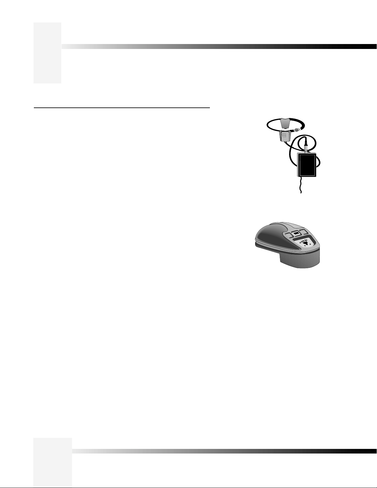
Student Camera Upgrade Package
Used in distance learning applications, this system gives each student the
power to be instantly identified by the camera with the touch of a press
to talk microphone. This includes theProgrammable Response Module
for distributed preset control and a 3-CCD Camera Control Keypad.
Presenter Camera Upgrade Package
The system gives presenters and instructors the ability to provide dynamic
presentations while the camera automatically follows their every move.
Includes a Tracking Ring Package, 3-CCD RF Tracking Keypad, and Main
Docking Station.
Personal Locator Upgrade Package
For videoconferencing applications, this system gives each videoconferencing
participant the power to be instantly identified by the camera with the touch of
a MY TURN button on individually controlled keypads. Includes three 3-CCD
RF Personal Locator Keypads and one RF Chairperson Locator Keypad for
distributed preset control.
Tracking Ring Package
for Presenter and Deluxe
Systems
.snoitacilppa gnicnerefnocoediv dna enicidemelet ,gninrael ecnatsid ni desU
Personal Locator Keypad
for Personal Locator and
Deluxe Systems
Deluxe Upgrade Package
Combines the distributed preset control of the Personal Locator System and
the autoTRACK presentation capabilities of the Presenter Camera System.
Includes three 3-CCD RF Personal Locator Keypads, one RF Chairperson
Locator Keypad, Tracking Ring Package, 3-CCD RF Tracking Keypad, and
Main Docking Station.
Page 2
CameraMan® 3-CCD DIGITAL Camera Installation and Operations Manual
Page 6
3-CCD Product Description
Recommended Accessories
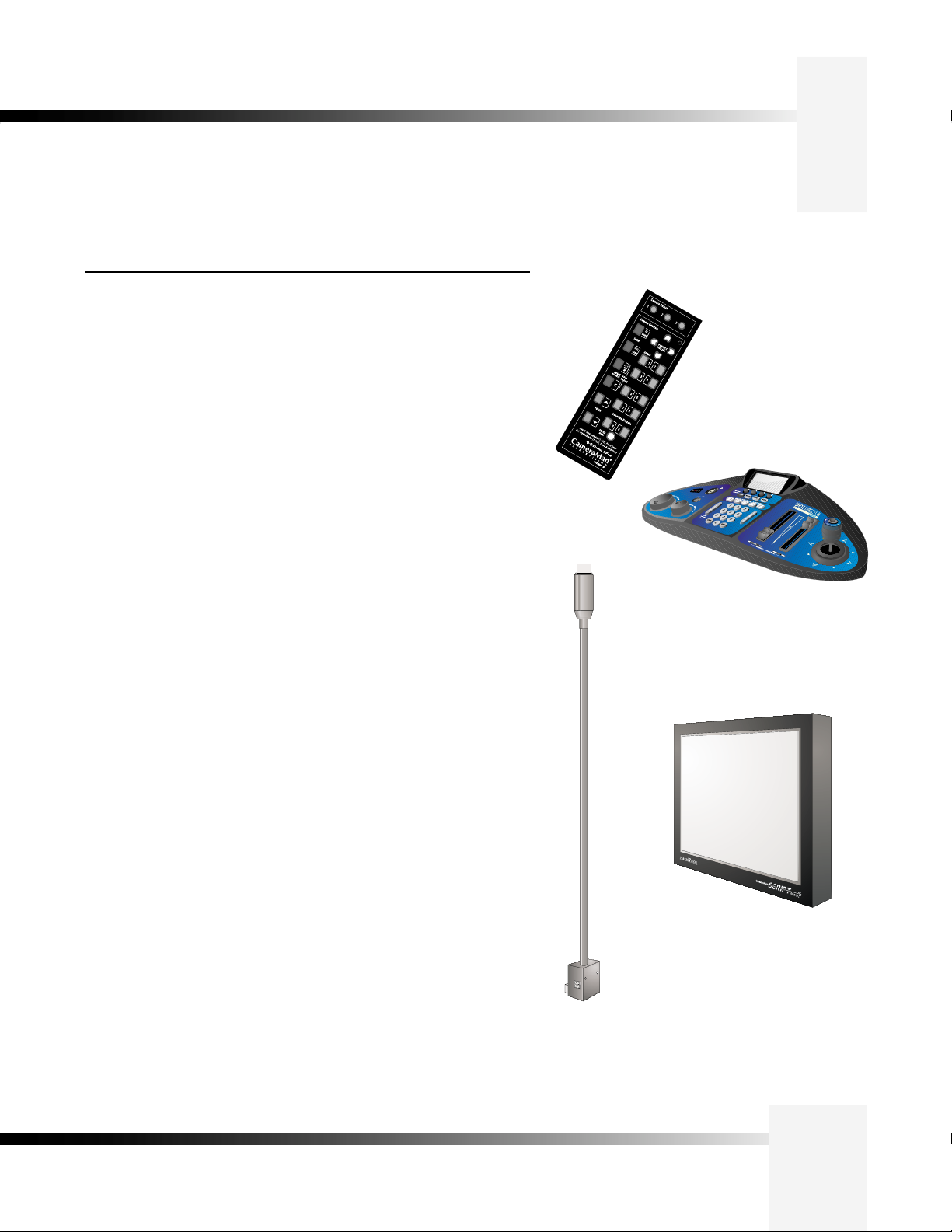
Camera Control Keypad
Whether used in wireless RF, or hard-wired mode, this keypad gives the ability
to control the pan, tilt, zoom, focus, iris, and location presets for up to three
separate cameras. The keypad comes standard with the Student Camera
System, and the Tracking Keypad comes standard with the Presenter and
Deluxe Camera Systems.
PVTV DIGITAL SHOT Director
Some applications require precise and flexible camera control. The
DIGITAL SHOT Director is a joystick controller designed to give ultimate
control by affording the ability to adjust to the pan, tilt, zoom, focus, iris,
CCU functions and location presets on 1 to 16 different cameras from one
location. And its built-in CCU functionality allows adjustment of each camera’s
on-screen image.
3-CCD Camera
Control Keypad
CameraMan Tally Light
For visual indication of which camera is selected in a multi-camera application,
the CameraMan Tally Light provides a high intensity indication from an easyto-install interface on the rear of the camera. A bright red indicator is mounted
to the top of a flexible pedestal, allowing precise adjustment and positioning
of the light for the best possible studio-wide observation. Control of the Tally
light can be accomplished through Control Center, and PVTV STUDIO, as well
All current 3-CCD cameras are Tally-light compatible, and previous models
are factory upgradeable.
PVTV SCRIPT Viewer Display
Adding a full-feature teleprompting display that moves with the camera is
now available with the addition of the powerful PVTV SCRIPT Viewer
system. The 12" active matrix, full color displays are available separately and
are easily mounted to the camera. Contact your reseller for more information
on the complete Script Viewer system.
PVTV DIGITAL SHOT Director
CameraMan
Tally Light
.rotcennoc xineohP detnuom-edis a ot detcennoc erusolc lanretxe na aiv sa
PVTV SCRIPT Viewer Display
3-CCD DIGITAL Camera
Page 3
Page 7
3-CCD DIGITAL Camera Components
Below is a description of each part that came with the CameraMan 3-CCD DIGITAL
Camera.
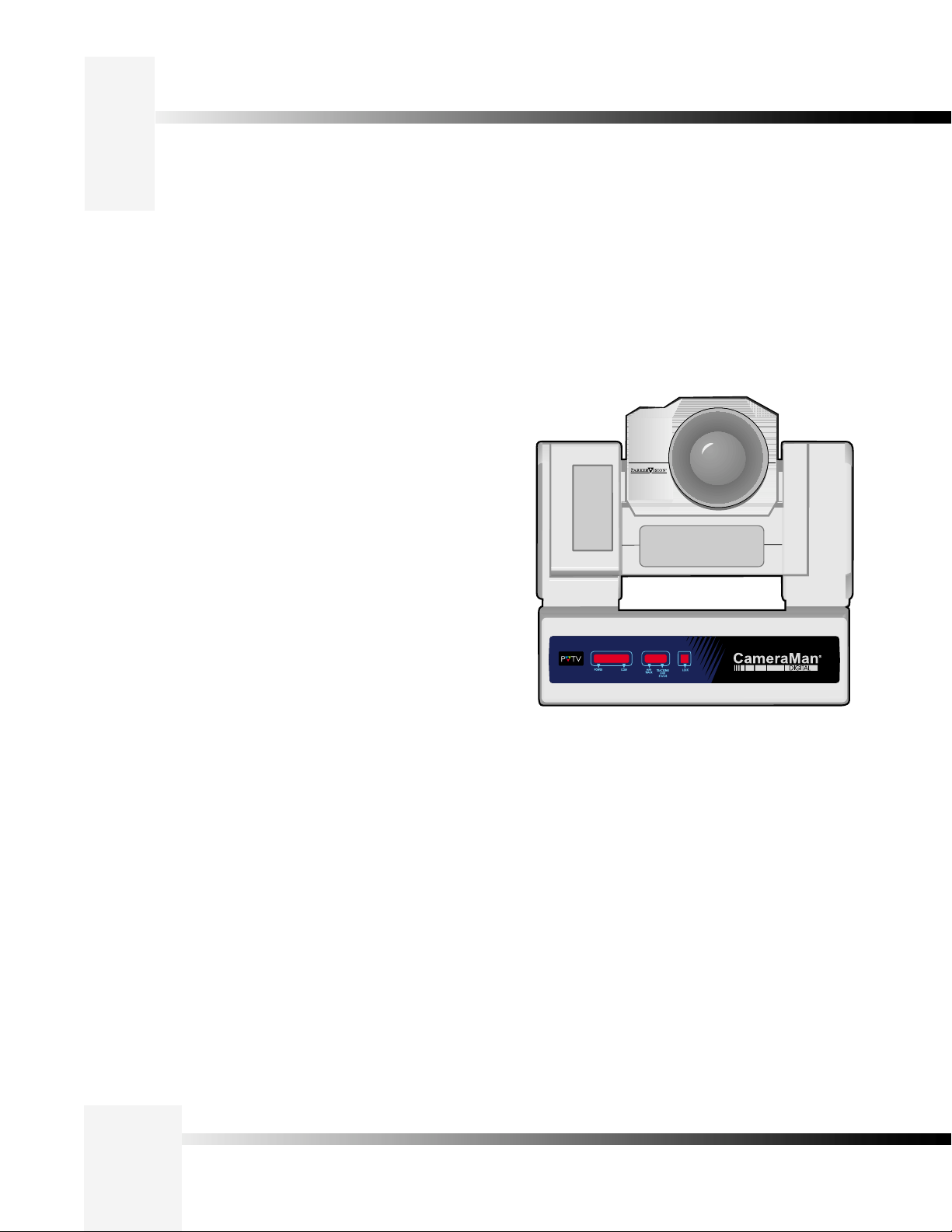
CameraMan 3-CCD DIGITAL Camera
The camera and its integrated intelligent pan/tilt system is the primary
component, and the basis for all CameraMan camera systems.
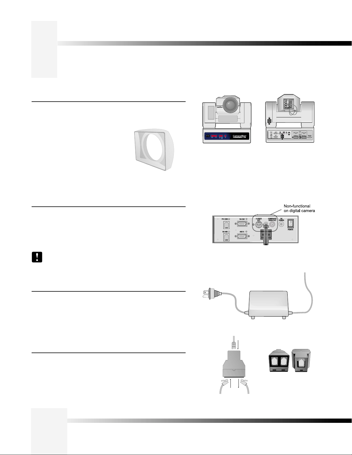
The 18x version of the 3-CCD DIGITAL
Camera includes a rectangular lens shroud.
See Appendix H: page 24 for instructions on
how to install the shroud.
Front View of CameraMan 3-CCD
DIGITAL Camera
Rear View of CameraMan 3-CCD
DIGITAL Camera
Mini Docking Station
The Mini Docking Station should be attached to the back of the camera.
This box is the point of connection for all RS-232 and RS-485. The only
time this box needs to be removed is if the camera is upgraded to a
Presenter Camera System.
Note: If a Presenter or Deluxe Camera System was purchased,
the Mini Docking Station is not needed.
CameraMan Power Supply
The included power supply enables use with 50/60 Hz, 100-240V Power
sources.
Connection Accessories
• RS-485 Connector “T”
• 3’ CameraMan Communication Cable
• 25’ CameraMan Keypad Cable
Mini Docking Station
Power Supply
Front and back of T-connector
Page 4
Top of T-connector with RS-485 cables.
CameraMan® 3-CCD DIGITAL Camera Installation and Operations Manual
Page 8
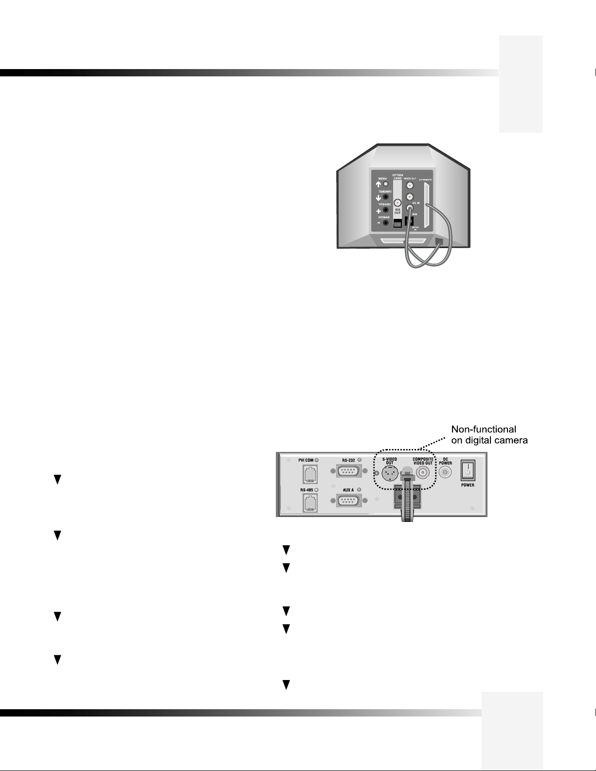
CameraMan Ports and Jacks
The back of the CameraMan 3-CCD DIGITAL Camera has a variety of ports and jacks
used to connect the camera to other video, audio, and camera control components in
a system.
MENU – Turns on the on-screen menu for appearance
adjustments. Also used to scroll upward through the
on-screen menus.
ITEM/AWC – When in shooting mode, the automatic
white balance control can be set with this switch. It can
also be used to scroll downward through the on-screen
menus.
YES/ABC – When in shooting mode, the automatic black
balance control can be set with this switch. It is also
used to display and increase the value of the sub-menus
of the main on-screen menu.
NO/BAR – When in shooting mode, the color bar and the
shooting conditions are alternately indicated by pressing
this switch. This is also used to scroll downward through,
or lower the value of sub-menu items.
SDI OUT – A digital video signal is provided at this
BNC connector.
VIDEO OUT – This is an ANALOG Video Out signal
which is utilized to view the on-screen menus.
G/L IN – A GEN LOCK BNC connector used to
synchronize the camera by connecting it to the network's
Video Timing Source.
IRIS – Input terminal for lens iris control.
DC12V IN – Not Used.
I/F REMOTE – Allows communication with the pan/tilt
unit.
Back of Camera Shroud
PVI COM Jack– Used by certain devices as a
communication interface to the camera system.
(For example, a hard-wired keypad would attach here).
This is a standard 6-conductor RJ-11 jack.
RS-485 Jack–- Used for RS-485 communications
between the camera system and other
devices. This jack can be used to network multiple
cameras or to connect appropriate, approved
peripherals using a T-connector. This is a
standard 4-position modular handset jack.
Auxiliary Communication Port– Provides
communications to select peripherals and
provides capability for future expansion.
RS-232 Port–Provides RS-232 communications to
external devices such as PC's or other vendor control
systems. This connector is a standard DB-9 (female)
connector.
Ports and Jacks
S-Video Jack–- Non-functional.
Cable Restrainer– Helps keep cables from
becoming disconnected, or hindering the pan and
tilt capabilities of the camera.
Composite Video Jack– Non-functional.
DC Power Jack– Power input for the CameraMan
Camera. Plug only the supplied power supply
into this jack. No other types of power
supplies should be used.
Power– Used to power on/off the CameraMan
Camera.
3-CCD DIGITAL Camera
Page 5
Page 9
CameraMan LED Displays
On the front of the DIGITAL CameraMan 3-CCD Camera, there are several LEDs.
These indicate various functions that are being performed by the camera. Below
is a description of each.
When the camera is first powered ON, all LEDs will illuminate. During this
time, basic system hardware checks are being performed. These checks
include communication with the camera interface board which verifies
proper installation of the caemra block on the pan/tilt unit. After the initial
system checks are completed, the LEDs will turn on and off one by one in a
binary pattern. This pattern represents the progress the camera is making
during hardware initialization. During this initialization, pan/tilt positions and
camera settings are being restored. Once initialization is complete, the
camera LEDs will represent the following functions:
Power–- Indicates that the camera has an active power supply and
is powered ON.
Setup– The camera is in the camera setup mode.
COM– Indicates that the camera is receiving valid network data on a
communication link (the LEDs on the back of the camera only indicate
line activity, not valid data).
autoTRACK– Indicates that the camera is in autoTRACK mode. The
IR spinners are running and the camera is attempting to acquire
data from the TRP.
Tracking Unit Status– Indicates that the camera has acquired the RF
signal from the TRP and is receiving valid data. When this LED is
OFF, TRP power is usually OFF.
Lock– This LED is used in the CLK/PLK package option only. There
are two types of keypads in this package: the Personal Locator
Keypad and the Chairman Locator Keypad. The Chairman Locator
Keypad has lock/unlock buttons on it that enable the CLK operator to
disable or override the PLK users. The LED is illuminated when the
CLK operator has disabled the PLK keypads by pressing the LOCK
button onthe CLK keypad.
Page 6
CameraMan® 3-CCD DIGITAL Camera Installation and Operations Manual
Page 10
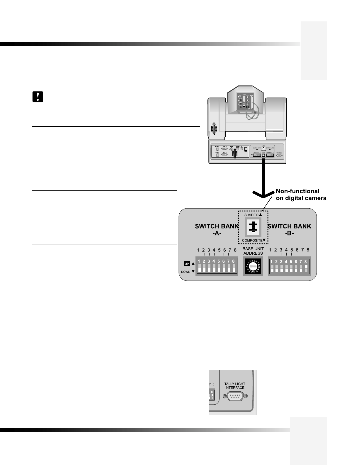
CameraMan Configuration Switches
Behind the configuration plate on the lower right side rear of the 3-CCD DIGITAL Camera
is the configuration panel. These DIP and rotary switches are used to link the camera’s
settings to other components in the system.
Note: After changing any switch’s settings, turn the camera off, then
back on to activate the change. Refer to page 12 for Dip Switch
configuration.
Switch Bank A
Switch 7 (Baud Rate Switch)– Used to change the camera’s Baud Rate.
Switch 8 (Memory Lock Select Switch)–Can be used to prevent
programmed settings from being accidentally overridden.
Switches 1, 2, 3, 4, 5 and 6— Reserved for future use.
Center Control Switches
Video Select Switch–Non-functional.
Base Unit Address–Used to configure the address of the
Camera.
Back of 3-CCD
DIGITAL Camera
Switch Bank B
Switch 1 (Protocol Select Switch) – Used to select the type of
Protocol being used for RS-232 and RS-485 communications.
This can be configured as either Basic or High Reliability.
Switch 4 (RF Commands Switch) – Used to enable or disable
the RF Receiver in the CameraMan camera.
Switch 5 (Preset Save) - Used to determine how the preset settings
will be saved.
Switch 8 (Interlink Switch) – Used to disable commands from being sent
on the RS-485 bus to other CameraMan devices.
Switches 2, 3, 6 and 7— Reserved for future use.
Tally Light Interface Port- Provides output and external control for
CameraMan Tally Light.
3-CCD DIGITAL Camera
Page 7
Page 11

Mounting the CameraMan 3-CCD DIGITAL Camera
Mount the DIGITAL Camera on any flat, non-slick, non-metal surface with a minimum
supporting area of 8”x8” by following these easy steps.
Step 1: Check the selected camera-location to ensure that there is enough
camera and cable clearance space (right) for the CameraMan to pan
and tilt without obstruction.
30.0"
Diameter
Note: Do not mount the camera upside down, or with more
than a 10° angle from horizontal.
Tip: See Appendix E: FIELD OF VIEW SPECIFICATIONS
on page 18, to assist in placing the CameraMan to achieve
optimum optical views.
Step 2: Locate the zero-degree position mark labeled FRONT on the bottom
of the base unit. This mark helps ensure that the base unit is
calibrated correctly. Point this indicator mark in the direction that best
reflects the center of travel in which the camera will be used (usually
the center of the room).
Step 3: To ensure that the camera-mounting is not prone to vibrations,
securely fasten the camera to a rigid flat surface using a 1/4"-20
UNC cap screw that does not extend into the base platform by more
than 0.4". (The screw hole is provided in the base platform for
this purpose. The cap screw is not provided.) This screw should
be hand-tightened. If necessary, use a non-hardening threadlock to
prevent the screw from loosening.
Note: Be sure to take environmental conditions into
consideration when operating the camera. Always operate
the camera indoors, and follow the temperature and
humidity specifications outlined in Appendix C: CAMERA
SPECIFICATIONS on page 16.
17.0"
Zero degree
position
mark
1/4”-20 UNC Mounting
Screw Hole
Page 8
CameraMan® 3-CCD DIGITAL Camera Installation and Operations Manual
Page 12

Connecting to the Camera System
Follow the instructions below to begin connecting the camera to the system.
Tip: After connecting each cable to the camera, let it hang
loosely behind the camera. Then follow the instructions in the
“Restraining the Cable Connections” section before attaching the
other ends of the cable to other equipment. This will relieve
undue stress on the cables, allowing the camera to move freely.
Connecting The Camera Control Cables
On the back of the camera shroud, there are two cables. These control
the camera’s lens, power and video signals. These must be attached for
the camera to operate properly.
•
Connect the 12-pin male connector (#1) to the IRIS jack.
•
Connect the 50-pin SCSI connector (#2) to the I/F REMOTE jack.
2
1
2
1
Connecting The SDI Video Output
The 3-CCD DIGITAL Camera supports SDI format (270 Mbls component
out).
Connect to the BNC jack labeled SDI OUT on the back of the camera
shroud, using a standard SDI coaxial cable with a BNC connector.
SDI OUT
Rear View of DIGITAL
Camera
3-CCD DIGITAL Camera
Page 9
Page 13

Connecting to the Camera System
Connecting ToThe RS-232 Port
The 3-CCD DIGITAL Camera provides for RS-232 communications using the
DB-9 jack on the back of the camera, labeled RS-232. This RS-232 port can
be used to control the CameraMan Camera from external devices such as
a PC or other vendor control system (i.e.: AMX, Crestron). Connect to this
port using a standard computer cable with a DB-9 connector. When used
with a PVTV DIGITAL SHOT Director, this port operates at 19,200 Baud, No
Parity and software hand-shaking using High Reliability protocol.
Otherwise, the port operates at 9600 Baud, No Parity, and software handshaking using High Reliability or Basic protocols.
Note: To verify which protocol is being used, check the PROTOCOL
switch on the configuration panel on the back lower-right of the
DIGITAL Camera.
Tip: The COM light above the RS-232 port is used to indicate
communication activity.
RS-232 Port on the Mini Docking
Station on the back of the 3-CCD
DIGITAL Camera
Page 10
CameraMan® 3-CCD DIGITAL Camera Installation and Operations Manual
Page 14

Connecting Camera Control Devices
There are several ways to control the CameraMan’s movement. The information below explains how to
connect and configure the optional Camera Control Keypad, or the PVTV DIGITAL SHOT Director.
Tip: For the DB-9 pinout port information, see the Appendix D: PIN-
OUT DIAGRAMS.
Connecting Optional Camera Control Devices
Note: Do not use the Camera Control Keypad and the CameraMan
SHOT Director at the same time
Camera Control Keypad (or Tracking System Keypad)
The optional Camera Control Keypad controls the camera’s movement via
wireless RF technology (up to 60 feet), or hard-wired connection (up to 250
feet). If you choose to use a Camera Control Keypad in the hard-wired mode,
follow these directions for installation.
1. Using the 25’ CameraMan Keypad Cable included with your camera,
connect one end of the cable to the RJ-11 type jack located in the
battery compartment of the keypad.
2. Connect the other end of the cable to the RJ-11 type jack on the back
of the camera, labeled PVI COM.
Tip: When the system is powered on, the light on the keypad
should illuminate momentarily, indicating the keypad is ready for
operation. The light located above the PVI COM port is used to
indicate communication activity.
Note: Using cable other than the supplied cable for the PVI
COM port may cause damage.
PVTV DIGITAL SHOT Director
The optional PVTV DIGITAL SHOT Director multi-camera controller can be
connected in hard-wired mode only. Follow these directions to connect the
DIGITAL SHOT Director to the CameraMan.
Camera Control
Keypad
connected via
PVI COM
1. Using a standard RS-485 cable, connect one end of the cable to one
of the RS-485 jacks (either one) on the back of the Shot Director.
2. Connect the other end of the cable to:
• The jack labeled RS-485 on the back of the CameraMan
connector box for single camera applications, or
• The T-Connector for multiple-camera applications. Then use the
provided 3’ CameraMan Communication Cable to connect the
T-connector to the camera’s RS-485 jack.
Note: If using a Camera Control Keypad or DIGITAL SHOT Director,
refer to its operations manual. If it is unavailable, contact your local
reseller.
3-CCD DIGITAL Camera
PVTV DIGITAL SHOT
Director connected via
RS-485
Page 11
Page 15

Cable Restraint and System Power
Notice that if left alone, the connected cables may impede the camera’s movement. To
combat this, the 3-CCD DIGITAL Camera comes equipped with two cable restrainers on
the left back, and on the Mini Docking Station. Follow the instructions below to properly
restrain the cables and power-up the camera.
Restraining The Cable Connections
For upper (ie GEN LOCK) cable connections (if used)
1. Locate the cable restraint on the back left side of the camera.
2. Insert cable(s) through the cable restraint from left to right.
Note: Allow 16” of cable between the restraint and the connection
port to provide enough slack for the camera’s tilting movement.
3. Tighten the restraint by pulling on the strap’s “free” end to prevent
any cable from becoming dislodged. (the cable restraint is reusable
and adjustable).
4. Group the cables with all the other cables connected to the connector
box and follow the instructions below to feed them through the lower
cable restraint.
Feed the upper cables from left to right through the upper
cable restraint, then bundle with the lower cables and feed
left to right through the lower restraint.
For lower cable connections
1. Insert all cables (upper and lower) through the cable restraint from left
to right. This will result in the cables being located approximately in
the center of the camera, instead of near the edge.
2. Tighten the restraint by pulling on the strap’s “free” end to prevent any
cable from becoming dislodged.
Note: To relieve undue stress on the camera and the cable
connections, it is important to fasten all cables using the cable
restrainer on the back of the camera.
Note: Be sure to leave enough slack in the cables for the camera
to pan left and right free of any constraints.
Connecting The Power Supply
Mount the Power Supply with any orientation, or on top of a table or roll-about
unit by using the following steps.
1. Verify that the POWER switch, on the back of the camera, is turned
OFF.
2. Plug the 5.5mm female connector from the power supply cord into the
DC POWER jack in the back of the camera.
3. Connect the other end of the power supply into a 120 VAC source.
Power
Connections
and Switches
Page 12
CameraMan® 3-CCD DIGITAL Camera Installation and Operations Manual
Page 16

Switch Configuration
Now that CameraMan is connected to the power supply and control devices, the DIGITAL Camera must
be configured to work in the desired application. To begin, remove the configuration plate on the back
right side of the camera by removing the two screws holding it in place. Behind it are the configuration
switches. From left to right, they are:
Example: Switch
in the down
position
Switch Bank A
Dip Switch 7 (Baud Rate)
This switch is used to
configure the camera’s Baud
Rate for the RS-232 and
RS-485 ports. Switch UP for
19,200 and DOWN for 9600.
(factory default: UP)
Dip Switch 8 (Memory)
For the majority of
applications, this switch
should be set to UNLOCK
(UP). When DOWN, all
programmed features are
locked and cannot be
overridden. (factory default:
UP)
Central Control Switches
Base Unit Address
Use the 16-position rotary switch
labeled BASE UNIT ADDRESS to
set the unique identification number
for this CameraMan. If using the
optional Keypad, DIGITAL SHOT
Director, or another control system,
refer to the documentation provided
with those accessories for proper
configuration.
For setting up a camera
network, see page 15,
Appendix B: MULTIPLE
CAMERA APPLICATIONS.
Switch Bank B
Dip Switch 1 (Protocol)
Select the communication protocol which will be used by the
RS-232 and RS-485 ports on the camera. The High Reliability
protocol includes some advanced error checking that is not
performed in the Basic protocol. (factory default: DOWN)
Dip Switch 4 (RF Command)
When this switch is DOWN, the camera responds to commands
sent from an RF Keypad. When it is UP, the RF receiver in the
camera is disabled and the camera cannot receive commands
directly from a wireless keypad. (factory default: DOWN)
When using multiple cameras networked on the
RS-485 bus, only one camera should have its RF
receiver enabled. Set switch 4 on the other cameras
to UP.
Dip Switch 5 (Preset Save)
Use this switch to determine how the preset settings will be
recalled. DOWN recalls your Manual Gain, Iris, and Focus
settings. UP recalls only the Auto settings for presets and
autoTRACK Views. (factory default: DOWN)
Dip Switch 8 (Interlink)
Use this feature in multi-camera applications. When it is
DOWN, all commands will be passed onto the RS-485
communication bus to the appropriate camera. For a singlecamera application, the setting of this switch does not matter.
(factory default: DOWN).
All switches not discussed on this page should remain in the DOWN or OFF position.
3-CCD DIGITAL Camera
Page 13
Page 17

System Startup
Once all necessary connections and configurations are made, you are ready to turn
on the system.
Powering On
1. Just switch the Power button on the back of the CameraMan DIGITAL
Camera to the ON position. The Camera should automatically enter its
position calibration mode and then stop at the zero degree point.
2. Verify that the camera is now facing in the direction the "FRONT" label was
pointing during mounting (see page 7).
3. If you are using the optional Camera Control Keypad or DIGITAL SHOT
Director, make sure its base unit address is the same as on the camera.
If they are, verify that the camera’s PAN and TILT functions are working
properly.
Tip: If the camera does not move, refer to the
TROUBLESHOOTING section of the Camera Control Keypad, or
DIGITAL SHOT Director manual.
If using more than one CameraMan 3-CCD DIGITAL Camera,
they need to be set up in a “daisy-chain” network
Back of DIGITAL Camera
with power supply
Page 14
CameraMan® 3-CCD DIGITAL Camera Installation and Operations Manual
Page 18

Appendix A: Troubleshooting
Should any problems occur with the CameraMan 3-CCD DIGITAL Camera, please refer
to the following guide. If questions or problems still exist after troubleshooting, please
contact your authorized, or contact Customer Support directly at (904) 596-3500.
Problem: The Camera’s Video is not working properly.
Solution: 1. Verify that the SDI OUT connection is being used on the
back of the camera shroud.
2. Verify that the video output of the camera is connected to
the appropriate video input on the switcher or CODEC.
Problem: No communications through the RS-232 port.
Solution: 1. Verify that the cable being used is wired correctly. (see
page 17)
2. Verify that the PROTOCOL SELECT switch on the rear
configuration panel is set properly. (see page 12)
3. Verify that the BASE UNIT ADDRESS on the rear
configuration panel is set properly.
4. Does the COM light above the RS-232 port on the back of
the camera blink when you send a command through this
port? If no, change the cable and retry.
5. Verify thatt the POWER LED, on the front of the camera,
is illuminated. Also verify that the 12VDC indicator, on the
rear of the camera block is, is illuminated. If the POWER
LED is not lit, check the POWER switch to make sure that
it is ON, then verify that the Power Supply is connected to
the camera properly. If the 12VDC LED on the rear of the
camera block is not illuminated, verify that the I/F Remote
SCSI cable is connected properly.
Back of 3-CCD CameraMan with
configuration plate removed
COM light
on RS-232
Connection
3-CCD DIGITAL Camera
Page 15
Page 19

Appendix B: Multi-Camera Applications
configuration by following these steps:
1. Connect the cameras together by plugging the
T-connector into the RS-485 port on the back of the camera.
2. Connect each camera using a 4-conductor cable, with 4-position
modular handset plugs wired "straight-through":
Pin 1......Pin 1
Pin 2......Pin 2
Pin 3......Pin 3
Pin 4......Pin 4
Note: Do NOT use a standard phone cable, as these are
wired differently and may cause damage.
3. Using the BASE UNIT ADDRESS rotary switch, which is located
on the back of the Camera, configure each camera with a unique
Base Unit Address. (i.e.: Camera One would be set with address 0,
Camera Two would be set with address 1, and so on)
4. In order to control each camera with your Camera Control Keypad,
the rotary switch inside the keypad battery compartment must
match the lowest Base Unit Address in your system. For example, if
the Base Unit Address switches are set according to the illustration
to the right, the rotary switch inside the keypad should be set
to zero. The Camera Control Keypad can control up to three
cameras.
Camera One
Page 16
Connector T
CameraMan® 3-CCD DIGITAL Camera Installation and Operations Manual
Camera Two
Camera Three
Page 20

Appendix C: Camera Specifications
This device complies with part 15 of the FCC rules. Operation is subject to the condition
that this device does not cause harmful interference. FCC identifier: JFECM003-AA.
3-CCD DIGITAL Camera
3-CCD DIGITAL Camera (1/2" CCD)
Image Sensor:.....(3) 1/2” interline, supersensitive CCD
Hor. Resolution:.......850 TV Lines (high band, DTL ON)
Aspect Ratio:.............................................................4:3
Pixels:.......................................768 (H) x 494 (V) pixels
S/N Ratio:............................................65 dB (DNR on)
Scanning:....................................................2:1 interlace
System:.................................................................NTSC
Scanning Frequency:.15.734kHz (hor), 59.94 Hz (vert)
Synchronizing:..................................Internal or external
Sensitivity:.....................................2000 lx, F11, 3200 K
Min. Illumination:...0.25 lx, F1.4, Night Eye HIGH mode
Registration:.........................................................0.05%
Contour Correction:....................Horizontal and Vertical
White Balance:........Auto (2 memories), 3200K, 5600K,
................................Fine Man, ATW
Black Balance:......................................................AUTO
Color Bar:......................SMPTE color bar (Setup 0/7.5)
Shutter Speed:........Synchro Scan:60.34 Hz-15.75 kHz
Step Shutter:.............OFF, 1/100, 1/250, 1/500, 1/1000,
..................................1/2000, 1/4000, 1/10000 s ELC
Gain:.......AGC low/high, 0 - 30 dB, Night Eye Low/High
Iris:............................................................Auto, Manual
Temperature:.......................-10° to 45° C
Humidity:.............................20 to 90% Non-condensing
Dimensions:......................US: 14”L x 13.5”W x 10.75”H
..........................INT:35.6cm L x 34.3cm W x 27.31cmH
Zoom Ratio:..............................................................18x
Focal Length:.............................................6.7 - 121mm
Angular F.O.V.:..............................51.1° x 39.4° (wide)
......................................................3.03° x 2.27° (tele)
Maximum Relative Aperature.........1:1.4 (f=6.7~91mm),
...........................................................1:1.85 (f=121mm)
3-CCD Switchable DIGITAL Camera (2/3" CCD)
Image Sensor:.....(3) 2/3” interline, supersensitive CCD
Hor. Resolution:.......850 TV Lines (high band, DTL ON)
Aspect Ratio:..................................4:3, 16:9 switchable
Pixels:.......................................948 (H) x 485 (V) pixels
S/N Ratio:............................................62 dB (DNR on)
Scanning:....................................................2:1 interlace
System:.................................................................NTSC
Scanning Frequency:.15.734kHz (hor), 59.94 Hz (vert)
Synchronizing:..................................Internal or external
Sensitivity:....................................2000 lx, F9.5, 3200 K
Min. Illumination:.............................2.0 lx (F1.7 + 30dB)
Registration:.........................................................0.05%
Contour Correction:....................Horizontal and Vertical
White Balance:........Auto (2 memories), 3200K, 5600K,
................................Fine Man, ATW
Black Balance:......................................................AUTO
Color Bar:......................SMPTE color bar (Setup 0/7.5)
Shutter Speed:........Synchro Scan:60.34 Hz-15.75 kHz
Step Shutter:.............OFF, 1/100, 1/250, 1/500, 1/1000,
......................................1/2000, 1/4000, 1/10000 s ELC
Gain:.....................................AGC, 0 - 30 dB, Night Eye
Iris:............................................................Auto, Manual
Temperature:.............................................-10° to 45° C
Humidity:.............................20 to 90% Non-condensing
Dimensions:......................US: 14”L x 13.5”W x 10.75”H
.........................INT: 35.6cm L x 34.3cm W x 27.31cmH
Zoom Ratio: ..............................................................18x
Focal Length:.....................................9 - 162mm (16:9),
..........................................................10.8~194mm (4:3)
Angular F .O.V (16:9)......................52.1° x 40.3° (wide),
........................................................3.11° x 2.33° (tele)
Angular FOV (4:3).....44° x 34°(wide), 2.6° x 1.9° (tele)
Maximum Relative Aperature.......1:1.4 (f=9.0~117mm),
.............................................................1:2.5 (f=162mm)
BOTH CAMERAS
Mechanical
Mechanical Drives:....WhisperDRIVE Plus™ Rated For
5000 Hrs. Of Continuous Motion
Tilt:............................± 25° (Speed: 1°/Sec to 50°/Sec)
Pan:............................359° (Speed: 1°/Sec to 45°/Sec)
Location Presets:.....................................................125
Location Preset Data:..........Pan, Tilt, Zoom, Focus, Iris
Location Preset Accuracy:.................................±0.125°
Inputs/Outputs
Video Output:.........Composite: 1V[p-p] (75 ohm) BNC
..........SDI: 270Mb/s component (SMPTE 259M) BNC
External Sync Input:......................................BB (BNC)
RS-232 Port:....................................DB-9(F) Connector
RS-485 Port:..............................Bus Up To 16 Cameras
.................................................(4 pos. RJ handset port)
Power:.................................100-240VAC Power Supply
......................................100 W Maximum Consumption
CameraMan Clearance
The minimum dimension for the CameraMan is a circular diameter of 30". This accounts for both camera and
cable clearance. Check cable movement to avoid binding and stress on the camera.
3-CCD DIGITAL Camera
Page 17
Page 21

Appendix D: Pin-Out Diagrams
The following pinout connections can be found on the back of the Mini Docking Station
on the rear of the CameraMan. These diagrams are for reference.
Pin Signal
1 12v
2 12v
3 Ground
PVI COM
RJ-11
4 Signal A
5 Signal B
6 Ground
+ 18v DC
Ground
RS-485
Four position
Modular
Handset
RS-232
9-pin Female D-9
Sub
Pin Signal
1 Ground
2 Signal A
3 Signal B
4 Ground
Pin Signal
2 Transmit
3 Receive
5 Ground
1,4,6-9 Not Used
5.5mm DC
Power
Connector
Page 18
CameraMan® 3-CCD DIGITAL Camera Installation and Operations Manual
Page 22

Appendix E: Field-Of-View Specifications
The reference charts below represent the size of the field of view and angle of view from
various distances and with different lenses.
18 x 6.7 Lens on Standard 4:3 DIGITAL Camera:
Dist. from Lens No Zoom Full Zoom
(feet) Hor. (ft) Vert. (ft) Square Feet Hor. (ft) Vert. (ft) Square Feet
10 9.56 7.16 68.47 0.53 0.40 0.21
15 14.34 10.74 154.05 0.79 0.59 0.47
20 19.12 14.32 273.87 1.06 0.79 0.84
25 23.90 17.90 427.91 1.32 0.99 1.31
30 28.68 21.48 616.20 1.59 1.19 1.89
35 33.46 25.06 838.71 1.85 1.39 2.57
40 38.54 28.64 1095.46 2.12 1.58 3.35
45 43.02 32.22 1386.44 2.38 1.78 4.24
50 47.80 35.81 1711.66 2.64 1.98 5.24
55 52.59 39.39 2071.10 2.91 2.18 6.34
60 57.37 42.97 2464.79 3.17 2.38 7.55
65 62.15 46.55 2892.70 3.44 2.58 8.86
70 66.93 50.13 3354.85 3.70 2.77 10.27
Angle of view 51.10° 39.40° 3.03° 2.27°
18 x 9 Lens on 16:9/4:3 DIGITAL Camera switched to 4:3 Aspect Ratio:
Without 0.8 Wide-angle Crossove Adaptor
Dist. from Lens No Zoom Full Zoom
(feet) Hor. (ft) Vert. (ft) Square Feet Hor. (ft) Vert. (ft) Square Feet
9.56 ft
7.16 ft
Example of distance’s impact on field of
view: taken from Standard Lens Table (10
feet and 20 feet)
14.34 ft
10.74 ft
10 8.18 6.11 50.03 0.46 0.35 0.16
15 12.27 9.17 112.57 0.69 0.52 0.36
20 16.36 12.23 200.12 0.92 0.69 0.63
25 20.46 15.29 312.69 1.15 0.86 0.99
30 24.55 18.34 450.28 1.38 1.04 1.43
35 28.64 21.40 612.88 1.61 1.21 1.94
40 32.73 24.46 800.50 1.84 1.38 2.54
45 36.82 27.52 1013.13 2.07 1.56 3.21
50 40.91 30.57 1250.78 2.30 1.73 3.97
55 45.00 33.63 1513.44 2.53 1.90 4.80
60 49.09 36.69 1801.12 2.75 2.07 5.71
65 53.18 39.74 2113.81 2.98 2.25 6.70
70 57.28 42.80 2451.52 3.21 2.42 7.77
Angle of view 44.50° 34.00° 2.63° 1.98°
3-CCD DIGITAL Camera
Above- Vertical angle of view:
Below- Horizontal angle of view:
no zoom= wide angle (more scenery, less
specific detail)
zoom= narrow angle (less scenery, more
specific detail)
Page 19
Page 23

Appendix E: Field-Of-View Specifications
The reference charts below represent the size of the field of view and angle of view from
various distances and with different lenses. When the camera is switched to a 4:3 aspect
ratio, the wide-angle conversion is at apporximately 11mm. To obtain the conventional 4:3
view, the user must use a wide-angle 0.8 crossover adapter.
18 x 9 Lens on 16:9/4:3 DIGITAL Camera switched to 4:3 Aspect Ratio:
With 0.8 Wide-angle Crossove Adaptor
Dist. from Lens No Zoom Full Zoom
(feet) Hor. (ft) Vert. (ft) Square Feet Hor. (ft) Vert. (ft) Square Feet
10 9.78 7.43 71.75 0.54 0.41 0.22
15 14.66 11.01 161.43 0.81 0.61 0.50
20 19.55 14.68 286.98 1.09 0.81 0.88
25 24.44 18.35 448.41 1.36 1.02 1.38
30 29.33 22.02 645.71 1.63 1.22 1.99
35 34.22 25.69 878.88 1.90 1.42 2.71
40 39.11 29.36 1147.93 2.17 1.63 3.53
45 43.99 33.02 1452.85 2.44 1.83 4.47
50 48.88 36.69 1793.64 2.71 2.03 5.52
55 53.77 40.36 2170.31 2.99 2.24 6.68
60 58.66 44.03 2582.84 3.26 2.44 7.95
65 63.55 47.70 3031.25 3.53 2.64 9.33
70 68.43 51.37 3515.54 3.80 2.85 10.82
Angle of view 52.10° 40.30° 3.11° 2.33°
18 x 9 Lens on 16:9/4:3 DIGITAL Camera switched to 16:9 Aspect Ratio:
Dist. from Lens No Zoom Full Zoom
(feet) Hor. (ft) Vert. (ft) Square Feet Hor. (ft) Vert. (ft) Square Feet
10 10.59 6.04 63.94 0.59 0.33 0.20
15 15.88 9.06 143.87 0.89 0.50 0.44
20 21.18 12.08 255.77 1.19 0.66 0.79
25 26.47 15.10 399.64 1.48 0.83 1.23
30 31.77 18.12 575.49 1.78 0.99 1.77
35 37.06 21.13 783.30 2.08 1.16 2.41
40 42.36 24.15 1023.09 2.37 1.33 3.15
45 47.65 27.17 1294.84 2.67 1.49 3.99
50 52.95 30.19 1598.57 2.97 1.66 4.92
55 58.24 33.21 1934.27 3.26 1.82 5.95
60 63.54 36.23 2301.94 3.56 1.99 7.09
65 68.83 39.25 2701.59 3.86 2.16 8.32
70 74.13 42.27 3133.20 4.16 2.32 9.65
Angle of view 55.80° 33.60° 3.40° 1.90°
Page 20
CameraMan® 3-CCD DIGITAL Camera Installation and Operations Manual
Page 24

Appendix F: The 18x Lens Shroud
The 18x verson of the CameraMan 3-CCD DIGITAL Camera comes equipped with a
rectangular lens shroud. The shroud helps to keep out glares from light sources located
on the sides of the camera.
Installing the Shroud
1. Locate the red dots on the top and bottom of the shroud, and on the
lens itself.
2. Align the red dot on the shroud with the dot on the lens, then slide the
shroud over the lens.
3. Tighten the shroud in place using the bolt attached to the shroud.
lens shroud
red alignment dots
tightening screw
camera lens
3-CCD DIGITAL Camera
Page 21
Page 25

Appendix G: Typical System Diagrams
Below is a typical setup for the CameraMan camera. The items in the diagram are not
to scale.
choose one option
SDI Video Out
AMX
or
Crestron
Page 22
CameraMan® 3-CCD DIGITAL Camera Installation and Operations Manual
Page 26

Appendix H: On-Screen Camera Menus
Use Mode Setting
The camera has four use modes, and various functions
for four use modes have been preset.
Functions can be set as best suited to each use mode.
• Halogen mode
Suited to indoor shooting, such as at weddings, parties, lecture meetings, events, etc.
Settings can be changed using a simple menu.
• Fluorescent mode
Suited to indoor shooting under fluorescent lighting.
Settings can be changed using a simple menu.
• Outdoor mode
Suited to outdoor shooting.
Settings can be changed using a simple menu.
• User mode
Settings can be changed using a detail menu.
SETTING BY CAMERA
1. Turn the camera on while keeping the MENU switch
depressed.
The use mode setting menu shown at right appears
on the monitor screen and one of the use mode
blinks.
2. Press the MENU switch, ITEM/AWC switch, or
NO/BAR switch to let the desired use mode blink.
MENU switch ( ): The blinking item moves up by
one.
ITEM/AWC switch( ), NO/BAR switch (–): The blink-
ing item moves down by one.
3. Press the YES/ABC switch.
The blinking use mode comes into effect. After the
use mode setting menu is shown for about 5 seconds, the camera returns to be ready for operation.
Then, the camera operates in the selected use mode.
POWER
OPERATE
BAR
CAM
MODE
GAIN AWC
SCENE
FILE
ABC
ATW
A
B
AUTO/AIW
ELC
LOW
MID
MANU
ON SC H
OFF
HIGH AGC
OFF
1 / 100
SHUTTER
ON
OFF
1
.
2
.
3
.
4
.
G/L PHASE
T.PED CABLE COMP
90° 180°
0° 270°
YC
SCENE FILE Switch
Operation mode
SETTING BY RCU (RCB) OR HYBRID
CONTROL PANEL
An operation mode is selected depending on the position
of the scene file switch.
Halogen Mode
Fluorescent Mode
Outdoor Mode
User's Mode
Scene File
Switch
Position of
RCU (RCB)
1
2
3
USER SET
Scene File
Switch
Position of
Hybrid control
panel
1
2
3
4
VIDEO OUT
G/L IN
I/F REMOTE
OPTION CARD
IRIS
DC12V IN
MENU
ITEM/AWC
YES/ABC
NO/BAR
MENU
R B
R B
PED
TOTAL
PED
A
B
ATW
AWC
AUTO
HOLD
ABC
IRIS
MAN
AUTO
1000
S/S
ELC
500
100
OFF
SHUTTER SCENE
21
3
USER
SET
AUTO/ATW
PAINTING
GAIN
ITEM/AWC
YES/ABC
NO/BAR
SCENE
FILE
Switch
CAMERA RCU (RCB)
Hybrid Control Panel
The 3-CCD DIGITAL Camera allows for adjustments to the camera settings via on-screen
menus by using the controls on the back of the camera block, the Camera Control
Keypad, or PVTV DIGITAL SHOT Director. These adjustments should be performed by
qualified technical personnel only. If your system includes a DIGITAL SHOT Director,
always use the DIGITAL SHOT Director’s LCD menus to make these adjustments.
On-screen menu items can only be viewed by connecting to the analog VIDEO OUT connector on the rear of the
camera block.
3-CCD DIGITAL Camera
Page 23
Page 27

Appendix H: On-Screen Camera Menus
MENU ITEM SETTING
• Each of the four use modes of the camera has a main
menu. (Shown at right)
• Each item of the main menu has a submenu, which
consists of several settings.
• These settings have been preset to the optimum values to suit each use mode, and can be changed to
suit actual shooting conditions.
• They can be set from the camera and RCU (RCB).
They can also be set from the hybrid control panel
using the switches, but the setting items are limited
because the menu is not shown.
Notes:
• Composite signals are output from the video out-
put regardless of the position ENC/VF of the RCU
(RCB) user set switch.
• [End] is displayed only in setting from the camera
alone.
MAIN MENU SCREEN
Main Menu of Halogen,
Fluorescent, Outdoor Mode
Main Menu of User Mode
SETTING
1. From the camera alone:
Keep the MENU switch depressed for 5 seconds
or more.
From RCU (RCB):
Set the user set switch in the pocket to the ON
position.
The main menu appears on the monitor screen.
2. Each time the MENU switch ( ), ITEM/AWC switch
( ), or NO/BAR switch (-) is
pressed, the blinking item moves up or down.
3. When the YES/ABC switch is pressed after selecting
the desired item to blink, the submenu for the selected item appears on the screen.
4. Select the desired item to be changed in its settings
using the the MENU switch ( ) and ITEM/AWC
switch ( ).
5. Press the YES/ABC switch (+) or NO/BAR switch (–)
to change the settings.
6. Select [Return] using the MENU switch and ITEM/
AWC switch, then press the YES/ABC switch to
return to the main menu.
7. After changing the settings, take the following steps.
Camera alone: Select [End] using the MENU switch
and ITEM/AWC switch and press the YES/ABC
switch.
RCU (RCB): Set the user set switch in the pocket to
the OFF position.
The camera will now operate according to the new
settings.
CAMERA
RCU (RCB)
Use Mode
Blinking
Page 24
CameraMan® 3-CCD DIGITAL Camera Installation and Operations Manual
MENU
ITEM/AWC
YES/ABC
NO/BAR
OPTION CARD
MENU
ITEM/AWC
YES/ABC
NO/BAR
USER SET SWITCH
OFFENC
PAGE ITEM UP DOWN
VF ON
USER SET
H.PHASE
COARSE FINE
0°
VIDEO OUT
G/L IN
IRIS
DC12V IN
SC PHASE
270°
I/F REMOTE
Page 28

Appendix H: On-Screen Camera Menus
• Settings enclosed in parentheses can be set with the RCU (RCB) switch or VR in RCU (RCB) mode.
• To return to the initial settings, refer to page 46.
SUB MENU (Halogen Mode, Fluorescent Mode, Outdoor Mode)
• ON is automatically selected when the electronic
shutter on the submenu [Other Set] is set to
[Auto ND]. OFF is selected when other than [Auto
ND] is selected.
• ON is selected when the SHUTTER switch is set to
[ELC] in RCU (RCB) mode, and OFF is selected
when it is set to other than [ELC].
Setting and Changing of the Setting
(Halogen Mode, Fluores-cent Mode,
Outdoor Mode)
Video Level Adjustment
[Picture Level: –50 - +50]
Convergence level of AUTO IRIS/AUTO GAIN UP/
AUTO ND (ELC) can be adjusted.
Detecting Ratio Adjustment [Light PEAK/AVG: P50
- A50]
The ratio of AUTO IRIS/AUTO GAIN UP/AUTO ND
(ELC) detected peak to average can be adjusted within a predetermined range.
Photometric Measurement Method Setting [Light
Area: All, Center, Top cut, BTM cut, R/L cut
A photometric measurement method can be selected
for AUTO IRIS/AUTO GAIN UP/AUTO ND (ELC).
All: All the screen area is measured.
Center: The screen is measured mainly in the center
area, about one-third of both the top and bottom
and one-third of both the right and left portions of
the screen are excluded from measurement.
Top cut: About one-third of the top part of the screen
is excluded from measurement.
BTM cut: About one-third of the bottom portion of the
screen is excluded from measurement.
Auto ND (ELC) Setting [Auto ND (ELC): ON/OFF]
ON: The electronic shutter is controlled to automati-
cally adjust the luminance.
OFF: Luminance is not automatically adjusted by the
electronic shutter.
All Center Top cut BTM cut R/L cut
SHUTTER
R/L cut: About one-third of both the right and left por-
tions of the screen are excluded from measurement.
Notes
R B
R B
PED
TOTAL
PED
A
B
ATW
AWC
AUTO
HOLD
ABC
IRIS
MAN
AUTO
1000
S/S
ELC
500
100
OFF
SHUTTER SCENE
21
3
USER
SET
AUTO/ATW
PAINTING
GAIN
Fluorescent
3-CCD DIGITAL Camera
Page 25
Page 29

Appendix H: On-Screen Camera Menus
• In case of settings on the camera alone or when the
iris switch on the RCU (RCB) is at [AUTO], the Auto
Gain Up control may not operate if the lens iris
switch is in the manual position.
• When the AGC switch on the hybrid control panel is
set to AGC, the Auto Gain Up control operates in
the HIGH position.
Auto Gain Up Control Setting [Auto Gain Up:
OFF/ LOW/HIGH]
LOW: The Auto Gain Up control with a maximum
gain increase of about 18 dB adjust the luminance automatically.
HIGH: The Auto Gain Up control with a maximum
gain increase of about 30 dB operates. If the
luminance is still insufficient, the Night Eye also
operates to adjust the luminance automatically.
OFF: No auto gain up takes place. (Gain can be
increased manually.)
Hybrid Control Panel
AGC
Manual Gain Up Control Setting [Manu Gain Up: 0
dB - 30 dB / NIGHT EYE]
Manual setting is possible only when the Auto Gain
Up control is in the OFF position.
0 dB: 0 dB should be selected in normal cases.
1 dB - 30 dB: Use this range if sufficient video output
cannot be obtained even when the lens iris is
opened in shooting dark scenes.
NIGHT EYE (Night Eye L/H): Use this mode if suffi-
cient video output cannot be obtained even if 30
dB gain up should be selected.
Night Eye can be selected to any of two (L or H)
levels.
Black Level Setting [Pedestal: –30 - +30]
The black level (pedestal) of the luminance (Y) signal
can be set. Used in adjusting the black levels of two
or more cameras.
Contrast Adjustment [Contrast (Gamma):
LOW/MID/HIGH]
Contrast can be adjusted to any of three levels.
Chroma Level Adjustment
[Chroma Level: –3 - +3]
Chroma Level can be decreased or increased to any
of three levels each.
Skin Color Adjustment [Flesh Tone: –3 - +3]
Skin color can be decreased or increased to any of
three levels each.
White Balance Setting [White Bal: ATW/AWC A/
AWC B/P SET 3 200K/P SET 5 600K]
ATW: The white balance is automatically adjusted to
be always right.
AWC A, AWC B: Once the white balance is adjusted
with the ITEM/AWC switch on the back of the
camera, it is no longer necessary to set the white
balance again if you simply select AWC A or AWC
B, provided that the camera is used under the
same conditions.
Fine color adjustment can be made after setting
AWC by red/blue gain adjustment in user mode or
from the RCU (RCB).
P SET 3 200K: The white balance is adjusted to 3
200K illumination.
P SET 5 600K: The white balance is adjusted to 5
600K illumination.
Manual GAIN
Notes
• Only 0 dB, 9 dB, or 18 dB can be selected in case of
using the RCU (RCB).
• 0 dB when the manual GAIN switch on the hybrid
control panel is at LOW, 9 dB when it is at MID, or
18 dB when it is at HIGH.
Notes
Hybrid Control Panel
Neither P SET 3 200K nor P SET 5 600K can be set
from the RCU (RCB) or the hybrid control panel.
Note
POWER
ON
OFF
OPERATE
GAIN AWC
HIGH AGC
MID
LOW
MANU
MODE
SHUTTER
BAR
ELC
1 / 100
OFF
CAM
AUTO/AIW
ATW
A
B
SCENE
FILE
.
1
.
2
.
3
.
4
ABC
POWER
ON
OFF
OPERATE
MID
GAIN AWC
HIGH AGC
ATW
LOW
MANU
MODE
SHUTTER
BAR
ELC
1 / 100
OFF
CAM
A
B
SCENE
FILE
.
1
.
2
.
3
.
4
ABC
AUTO/AIW
G/L PHASE
ON SC H
90° 180°
0° 270°
OFF
T.PED CABLE COMP
YC
G/L PHASE
ON SC H
90° 180°
0° 270°
OFF
T.PED CABLE COMP
YC
Page 26
CameraMan® 3-CCD DIGITAL Camera Installation and Operations Manual
Page 30

Appendix H: On-Screen Camera Menus
Neither Sharpness nor Super DTL is valid for contour
correction if Detail Level setting is in the OFF position.
Detail Level Setting [Level: OFF/LOW/HIGH]
Detail level can be adjusted when Detail Select setting is at Sharpness. Super DTL level can be
adjusted when it is at Super DTL.
In case of using the RCU (RCB), the above can be
adjusted with the contour correction switch (DTL).
Noise Suppress Level Setting [Noise Suppress:
OFF/LOW/HIGH]
Screen noise can be reduced when Detail Level setting is at HIGH or LOW.
Clean DNR Setting [Clean DNR: OFF/LOW/HIGH]
Clean DNR effect can be selected.
Detail Flesh Tone Level Setting [DTL Flesh Tone:
LOW/MID/HIGH]
LOW: Skin color coarseness is suppressed.
MID: Standard
HIGH: Skin color is emphasized.
Electronic Shutter Setting [Shutter Speed: OFF/
1/100 to 1/10 000 / S/Scan / Auto ND]
OFF: Electronic shutter is turned off.
1/100, 1/250, 1/500, 1/1 000, 1/2 000, 1/4 000, 1/10 000:
Electronic shutter operates at one of these
speeds as selected.
S/Scan (Synchro Scan): Electronic shutter operates
at the speed set with the electronic shutter synchro-scan setting .
Auto ND: Electronic shutter is controlled to automati-
cally adjust the luminance. (ELC)
Note
Highlight Chroma Setting [Highlight Chroma:
OFF/LOW/HIGH]
At LOW or HIGH, the color dynamic range widens to
prevent highlighted white portions from suppression.
Color Bar Setup Setting [Color Bar Set:
0.0 IRE/7.5 IRE]
The setup level of color bar can be adjusted.
Horizontal Phase Adjustment
[H Phase: –206 - +49]
Horizontal phase can be adjusted when a genlock
signal is supplied.
Sub Carrier Phase Coarse Adjustment
[SC Coarse: 1/2/3/4]
Coarse adjustment of subcarrier phase can be made
when a genlock signal is supplied.
Subcarrier Phase Fine Adjustment [SC Fine: –511
- +511]
Fine adjustment of subcarrier phase can be made
when a genlock signal is supplied.
Detail Select Setting [DTL Select: Sharpness/
Super DTL]
If contour correction is not sufficient at the Sharpness
position when Detail Level setting is set to LOW or
HIGH, select the Super DTL position.
• In case of using the RCU (RCB), none of the shutter
speeds-1/250, 1/2 000, 1/4 000, and 1/10 000 can
be selected.
• In case of using the hybrid control panel, only OFF,
1/100, or Auto ND (ELC) can be selected.
• If the lens iris switch is at M (Manual) when operat-
ing the camera alone or when the iris switch on the
RCU (RCB) is at AUTO, Auto ND may not function.
Set the lens iris switch to A (Auto).
• Flickering may increase at Auto ND under fluores-
cent lights.
• Auto ND is automatically selected if Auto ND (ELC)
setting is set to ON.
Notes
3-CCD DIGITAL Camera
Page 27
Page 31

Appendix H: On-Screen Camera Menus
Shutter Speed
OFF
1/100
1/250
1/500
1/1 000
1/2 000
1/4 000
1/10 000
Electronic Shutter Synchro-Scan Setting [Synchro
Scan: 60.34 Hz - 15.75 kHz]
This setting is possible only when Electronic Shutter
setting is at S/Scan.
Horizontal bar noise can be reduced by synchro-scan
adjustment in shooting workstation scenes, for example.
*
For luminance settings at each shutter speed and synchro-scan shutter speed, refer to the table below.
Required luminance ratio
1
2
4
8
16
32
64
160
Synchro-scan
-
99.68 Hz
250.0 Hz
492.2 Hz
984.4 Hz
1.969 kHz
3.938 kHz
7.875 kHz
CCD Read Out Mode Setting [V Resolution:
Normal/Fine]
Normal: Normal image. (CCD storage will be by field
storage.)
Fine: Vertical resolution increases. (Vertical resolution
is raised without increasing residual images by
frame storage and electronic shutter.
Normal is recommended for general use be-cause
sensitivity will decrease at the Fine setting.
PC Control Access Speed Setting [Baud Rate:
1 200 bps/2 400 bps/4 800 bps/9 600 bps]
Select a communication speed in controlling the camera from the computer.
Negative/Positive Selection
[Nega/Posi: Posi/Nega]
Posi: Normal image
Nega: Image is shown reversed in darkness and
color.
Sub Menu (User Mode)
• Settings enclosed in parentheses can be set with the RCU (RCB)
switch or VR in RCU (RCB) mode.
• To return to the initial settings, refer to page 46.
Page 28
CameraMan® 3-CCD DIGITAL Camera Installation and Operations Manual
Page 32

Setting to initial set
In case of the wrong setting in any use mode, take the
following steps to return to the initial settings.
(1) Select [Initialize Data] on the main menu screen of
each Use Mode. (See page 29.)
Press the YES/ABC switch, then [Initialize Data]
screen shown for about 10 seconds.
(2)Press the YES/ABC switch within about 10 seconds to
return to the initial settings, the existing settings are
initialized, the screen shown at , and the camera
returns to main menu.
(3) If the NO/BAR switch is pressed, or if the YES /ABC
switch is not pressed, within about 10 seconds, the
screen shown at , and the camera returns to main
menu, and the existing settings are not initialized.
Item
±0
0
Top cut
ON
HIGH
--–10
MID
G/L. Color
Bar Set
±0
1
±0
7.5 IRE
INITIAL SETTINGS OF THE SETTING ITEMS
(Factory preset values)
• Halogen, Fluorescent, Outdoor Mode
Picture Level
Light PEAK/AVG
Light Area
Auto ND (ELC)
Auto Gain Up
Manu Gain Up
Pedestal
Contrast (Gamma)
Brightness
Set
Other Set
Shutter Speed
Synchro Scan
V Resolution
Baud Rate
Nega/Posi
+2
±0
ATW
OFF
Sharpness
HIGH
OFF
OFF
MID
Auto ND
--Normal
9600bps
Posi
Outdoor mode
+1
±0
AWC A
OFF
±0
1
±0
7.5 IRE
Sharpness
HIGH
OFF
OFF
MID
OFF
--Normal
9600bps
Posi
±0
0
Top cut
OFF
OFF
0dB
±0
MID
Fluorescent mode
±0
±0
AWC A
OFF
±0
1
±0
7.5 IRE
Sharpness
HIGH
OFF
OFF
MID
OFF
--Normal
9600bps
Posi
±0
0
Top cut
OFF
OFF
0dB
±0
MID
Halogen mode
Chroma Level
Flesh Tone
White Bal
High-light Chroma
H Phase
SC Coarse
SC Fine
Color Bar Set
DTL Select
Level
Noise Suppress
Clean DNR
DTL Flesh Tone
Color Set
Sharpness
(DTL) Set
Appendix H: On-Screen Camera Menus
3-CCD DIGITAL Camera
Page 29
Page 33

 Loading...