

Page 1
CameraMan
3-CCD ANALOG ROBOTIC CAMERA SYSTEM
Installation and Operation Manual
L1207101 Rev B
1998
Page 2

Contacting Grass Valley
Region Voice Fax Address Web Site
North America (800) 547-8949
Support: 530-478-4148
Pacific Operations +852-2585-6688
Support: 852-2585-6579
U.K., Asia, Middle East +44 1753 218 777 +44 1753 218 757
France +33 1 45 29 73 00
Germany, Europe +49 6150 104 782 +49 6150 104 223
Copyright © Grass Valley. All rights reserved.
Grass Valley Web Site
The www.thomsongrassvalley.com web site offers the following:
Online User Documentation — Current versions of product catalogs, brochures,
data sheets, ordering guides, planning guides, manuals, and release notes
in .pdf format can be downloaded.
FAQ Database — Solutions to problems and troubleshooting efforts can be
found by searching our Frequently Asked Questions (FAQ) database.
Sales: (530) 478-3347
Support: (530) 478-3181
+852-2802-2996
Grass Valley
P.O. Box 599000
Nevada City, CA 95959-7900
USA
www.thomsongrassvalley.com
Software Downloads — Software updates, drivers, and patches can be down-
loaded.
launaM noitarepO dna noitallatsnI naMaremaC
Page 3

CameraMan®3-CCD Camera System Installation and Operations Manual
Table Of Contents
I. Meet Your CameraMan
? Congratulations on your Purchase. . . . . . . . . . . . . . . . . . . . . . . . . . . . . . 1
? 3-CCD Product Description. . . . . . . . . . . . . . . . . . . . . . . . . . . . . . . . . . 2-3
? 3-CCD Camera System Components . . . . . . . . . . . . . . . . . . . . . . . . . . . . 4
? CameraMan Ports and Jacks. . . . . . . . . . . . . . . . . . . . . . . . . . . . . . . . . . 5
? CameraMan Conguration Switches . . . . . . . . . . . . . . . . . . . . . . . . . . . . 6
II. Connect Your CameraMan
? Mounting Your CameraMan. . . . . . . . . . . . . . . . . . . . . . . . . . . . . . . . . . 7
? Connecting to the Camera System
Connecting the Camera Control Cables . . . . . . . . . . . . . . . . . . . . 8
Connecting the Video Output (on connector box) . . . . . . . . . . . . . 8
Connecting the Video, RGB/Sync, and Genlock (if needed) . . . . . . 9
Connecting to the RS-232 Port. . . . . . . . . . . . . . . . . . . . . . . . . . . 9
? Connecting Camera Control Devices . . . . . . . . . . . . . . . . . . . . . . . . . . . 10
? Cable Restraint and System Power
Restraining the Cable Connections . . . . . . . . . . . . . . . . . . . . . . . 11
Connecting the Power Supply . . . . . . . . . . . . . . . . . . . . . . . . . . 11
III. Congure Your CameraMan
? Switch Conguration . . . . . . . . . . . . . . . . . . . . . . . . . . . . . . . . . . . . . . 12
IV. Use Your CameraMan
? System Startup . . . . . . . . . . . . . . . . . . . . . . . . . . . . . . . . . . . . . . . . . . 13
V. Appendices
? A: Troubleshooting . . . . . . . . . . . . . . . . . . . . . . . . . . . . . . . . . . . . . . . 14
? B: Multiple Camera Applications . . . . . . . . . . . . . . . . . . . . . . . . . . . . . . 15
? C: Camera Specications . . . . . . . . . . . . . . . . . . . . . . . . . . . . . . . . . . . 16
? D: Pin-out Diagrams . . . . . . . . . . . . . . . . . . . . . . . . . . . . . . . . . . . . . . . 17
? E: Field-of -View Specications . . . . . . . . . . . . . . . . . . . . . . . . . . . . . . . 18
? F: Typical System Diagram . . . . . . . . . . . . . . . . . . . . . . . . . . . . . . . . . . 19
? G: On-Screen Camera Menus . . . . . . . . . . . . . . . . . . . . . . . . . . . . . . 20-23
? H: The 18x Lens Shroud . . . . . . . . . . . . . . . . . . . . . . . . . . . . . . . . . . . . 24
Page 4

Page 1
Meet Your 3-CCD Camera System
This manual will introduce you to your new CameraMan, explain how to install, connect and
configure it, and how to use it in single, and multi-camera network applications. In addition,
you will find handy diagrams and charts in the appendices, providing you with technical
specifications.
You will see two icons throughout the manual:
This icon alerts you to important instructions in the operation and maintenance of
your CameraMan System.
This icon alerts you to tips or noteworthy suggestions in the operation or
maintenance of your CameraMan System
Congratulations On Your Purchase
Your new CameraMan 3-CCD General Pan/Tilt Camera is unmatched in quality, flexibility and expandability, providing you with one of the
best video-communications cameras in the industry.
Your 3-CCD General Pan/Tilt Camera System
should include these components:
• One 3-CCD CameraMan Camera (with 13x or 18x lens)
• One CameraMan Connector Box (unless purchased with
Presenter or Deluxe Camera Systems)
• One CameraMan Power Supply.
• One RS-485 Connector “T”
• One 3’ CameraMan Communication Cable
• One 25’ CameraMan Keypad Cable
• One 3-CCD Installation and Operations Manual
Page 5
Page 2
CameraMan®3-CCD Camera System Installation and Operations Manual
3-CCD Product Description
Your new 3-CCD General Pan/Tilt Camera System is designed to be used in a variety of applications. You may have purchased this
camera with one of the below packages. Below you’ll find information on upgrade paths, and recommended accessories.
Product Description
The 3-CCD CameraMan’s pan/tilt functions, zoom perspective, focus and IMAGE settings can
be controlled via the Remote Control Keypad, CameraMan SHOT DIrector, or
Tracking Keypad. In addition to the camera-control these optional accessories provide, they also
provide multi-camera control and store up to 125 presets per camera.
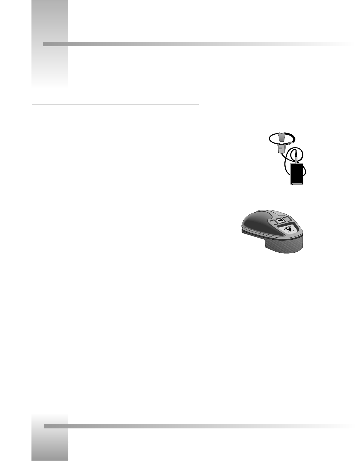
Student Camera Upgrade Package
Used in distance learning applications. This system gives each student the power to be instantly
identied by the camera with the touch of a press to talk microphone.
Includes Programmable Response Module for distributed preset
control and a 3-CCD Camera Control Keypad.
Presenter Camera Upgrade Package
Used in distance learning, telemedicine and videoconferencing applications. The system gives
presenters and instructors the ability to provide dynamic presentations while the camera
automatically follows their every move. Includes a Tracking Ring Package, 3-CCD RF Tracking
Keypad, and Main Docking Station.
Personal Locator Upgrade Package
For videoconferencing applications. This system gives each videoconferencing participant the
power to be instantly identied by the camera with the touch of a MY TURN button on
individually controlled keypads. Includes three 3-CCD RF Personal Locator Keypads and one RF
Chairperson Locator Keypad for distributed preset control.
Deluxe Upgrade Package
Combines the distributed preset control of the Personal Locator System and the autoTRACK
presentation capabilities of the Presenter Camera System. Includes three
3-CCD RF Personal Locator Keypads, one RF Chairperson Locator Keypad, Tracking Ring
Package, 3-CCD RF Tracking Keypad, and Main Docking Station.
Personal Locator
Keypad for Personal
Locator and Deluxe
Systems
Tracking Ring Package
for Presenter and
Deluxe Systems
Page 6
Page 3
Meet Your 3-CCD Camera System
3-CCD Product Description
Recommended Accessories
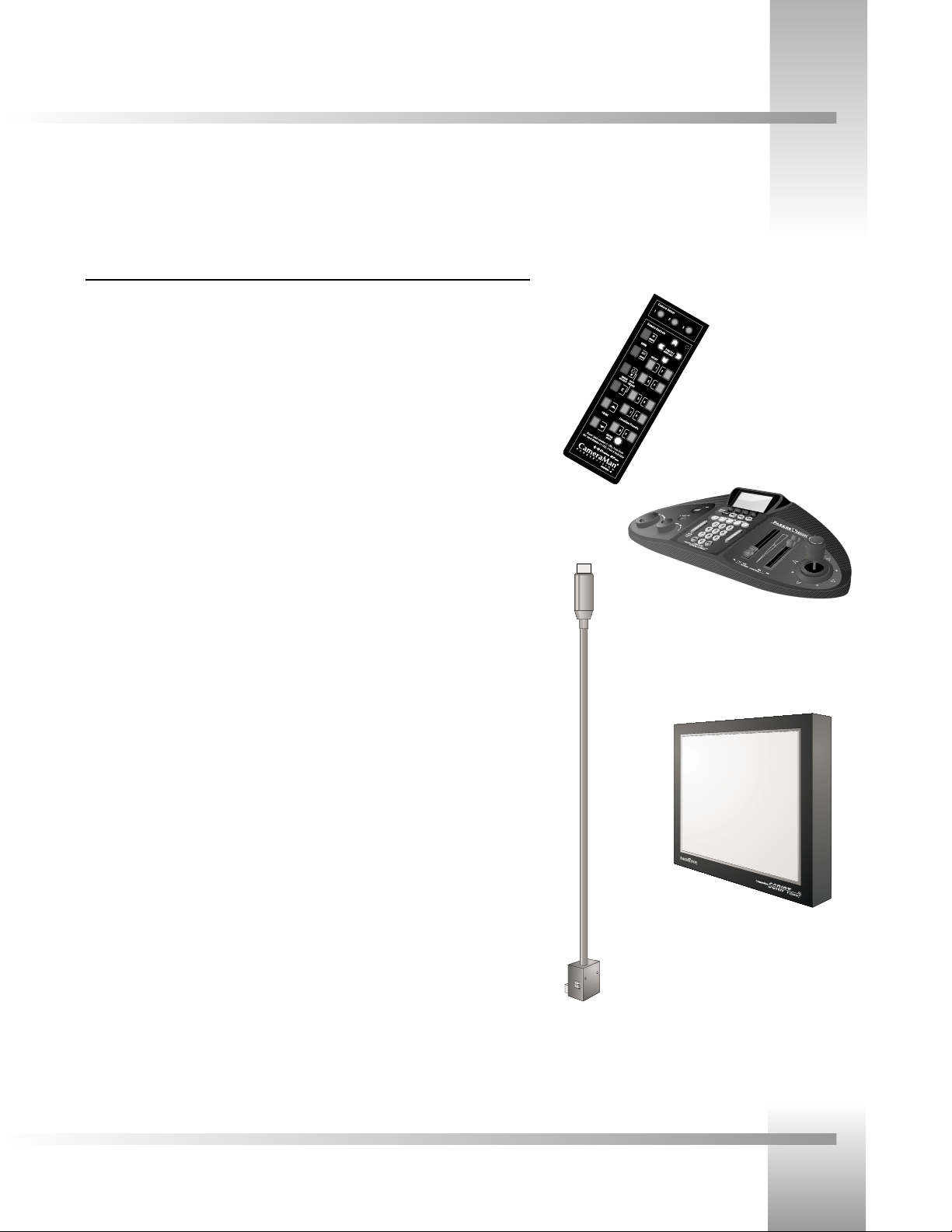
Camera Control Keypad
Whether used in wireless RF, or hard-wired mode, this keypad gives you the ability to control
the pan, tilt, zoom, focus, IMAGE, and location presets for up to three separate cameras. The
keypad comes standard with the Student Camera System, and the Tracking Keypad comes
standard with the Presenter and Deluxe Camera Systems
CameraMan Shot Director
Some applications require precise and exible camera control. The CameraMan Shot
Director is a joystick controller designed to give you the ultimate in single, and multi-camera
control by giving you the ability to adjust to the pan, tilt, zoom, focus, iris, CCU functions and
location presets on up to 16 dierent cameras from one location. And its built-in CCU
functionality allows you to adjust each camera’s on-screen image. The CameraMan Shot
Director is available in standard, and autoTRACK-equipped models.
CameraMan Tally Light
For visual indication of which camera is selected in a multi-camera application, the CameraMan
Tally Light provides a high intensity indication from an easy-to-install interface on the rear of
the camera. A bright red indicator is mounted to the top of a exible pedestal, allowing
precise adjustment and positioning of the light for the best possible studio-wide observation.
Control of the Tally light can be accomplished through the Shot Director, Control
Center, SCRIPT Viewer and CameraMan STUDIO, as well as via an external closure connected
to a side-mounted Phoenix connector. All current 3-CCD cameras are Tally-light compatible,
and previous models are factory upgradeable.
CameraMan SCRIPT Viewer Display
Adding a full-feature teleprompting display that moves with the camera is now available with
addition of the powerful CameraMan SCRIPT Viewer system. The 12" active matrix,
full color displays are available separately and are easily mounted to the camera. Contact your
reseller for more information on the complete Script Viewer system.
CameraMan Shot
Director
3-CCD Camera
Control Keypad
CameraMan Tally Light
CameraMan SCRIPT
Viewer Display
Page 7

Page 4
CameraMan®3-CCD Camera System Installation and Operations Manual
On page one of this manual, you’ll find a list of the components that came with your 3-CCD General Pan/Tilt Camera System.
Below, you’ll find a short description of each.
3-CCD CameraMan camera
The camera and its integrated intelligent pan/tilt system is the primary component, and
the basis for all of the CameraMan camera systems.
The 18x version of the 3-CCD camera includes
a rectangular lens shroud. See Appendix H:
page 24 for instructions on how to install the
shroud.
CameraMan Connector Box
The connector box should be attached to the back of the camera. This box is the point of
connection for all RS-232, RS-485 and video signals. The only time you would need to
remove this box is if you are upgrading this camera to a Presenter Camera System.
Note: If you purchased a Presenter or Deluxe Camera System, you will not need
a connector box
CameraMan Power Supply
The included power supply enables use with 50/60 Hz, 100-240V Power sources.
Connection Accessories
• RS-485 Connector “T”
• 3’ CameraMan Communication Cable
• 25’ CameraMan Keypad Cable
3-CCD Camera System Components
Power Supply
Connector Box
Top of
T-connector
with RS-485
cables.
Front and back of T-connector
Page 8
Page 5
Meet Your 3-CCD Camera System
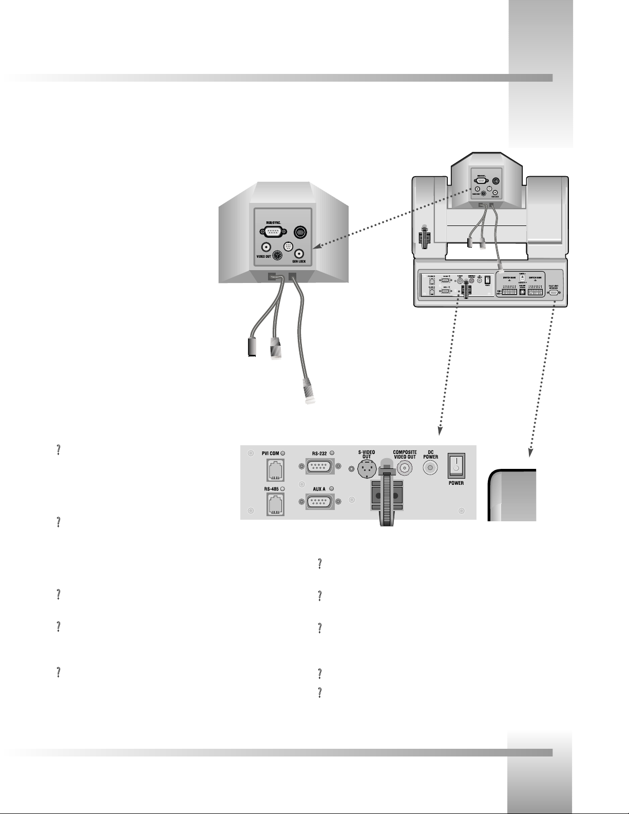
The back of your new CameraMan has a variety of ports and jacks used to connect your camera to other video, audio, and camera
control components in your system.
CameraMan Ports and Jacks
?
Cable Restrainer– Helps keep cables from becoming disconnected, or
hindering the pan and tilt capabilities of the camera.
?
Composite Video Jack– Provides direct composite video output. Connector
is a standard BNC-type jack. Video cable is not provided.
?
DC Power Jack– Power input for the CameraMan Camera. Plug only the
provided power supply into this jack. No other types of power
supplies should be used.
?
Power– Used to power on/o the CameraMan Camera.
?
Tally Light Port- Provides output and external control for CameraMan Tally
Light.
?
PVI COM Jack– Used by certain
devices as a communication interface to the
camera system. (For example, a hard-wired keypad
would attach here). This is a standard 6-conductor
RJ-11 jack.
?
RS-485 Jack–- Used for RS-485 communications
between the camera system and other devices.
This jack can be used to network multiple cameras or to connect
appropriate, approved peripherals using a Grass Valley Tconnector. This is a standard 4-position modular handset jack.
?
Auxiliary Communication Port– Provides communications to select
Grass Valley peripherals and provides capability for future expansion.
?
RS-232 Port–Provides RS-232 communications to external devices such as
PC's or other vendor control systems. This connector is a standard DB-9
(female) connector.
?
S-Video Jack–- Provides direct S-VIDEO video output. Connector is a
standard mini DIN jack. S-Video cable is not provided.
▼▼
RGB/Sync. Port– DB-9 connection that provides
RGB/Sync, component, Y/C, and composite video
signal output.
▼▼
Video Out Jack– Aux BNC connection for
composite video output.
▼▼
Gen Lock Jack– BNC connection used to
synchronize the camera to an outside sync
source.
▼▼
Camera Control Cables and Jacks– The three
cables connect to the 12, 8 and 20-pin jacks to
control the camera’s lens, power and video signals.
Back of 3-CCD
CameraMan with
connector box attached
and configuration plate
removed
Back of Camera
Shroud
Ports and Jacks
Tally Light Port
Page 9
Page 6
CameraMan®3-CCD Camera System Installation and Operations Manual
Switch Bank A
▼▼
Switch 2 (Sub-Carrier Coarse Adjustment Switch)–Used to change the
sub-carrier phase from 0° to 180°.
▼▼
Switch 7 (Baud Rate Switch)– Used to change the camera’s Baud Rate.
▼▼
Switch 8 (Memory Lock Select Switch)–Can be used to prevent programmed settings from being
accidentally overridden.
▼▼
Switches 1, 3, 4, 5 and 6— Reserved for future use.
Center Control Switches
▼
Video Select Switch–Used to select the Video
Output Format. This can be configured as either
Standard Composite or S-Video.
▼▼
Base Unit Address–Used to configure the address
of the Camera.
Switch Bank B
▼▼
Switch 1 (Protocol Select Switch) – Used to select the type of Protocol being used for RS-232 and RS-485
communications. This can be configured as either Basic or High Reliability.
▼▼
Switch 2 (Camera Data Local/Remote Select) – Used to determine whether the camera will receive data from a local
source or a remote source, such as a joystick.
▼▼
Switch 4 (RF Commands Switch) – Used to enable or disable the RF Receiver in the CameraMan camera.
▼▼
Switch 5 (Preset Save) - Used to determine how the preset settings will be saved.
▼▼
Switch 8 (Interlink Switch) – Used to disable commands from being sent on the RS-485 bus to other CameraMan
devices.
▼▼
Switches 3, 6 and 7— Reserved for future use.
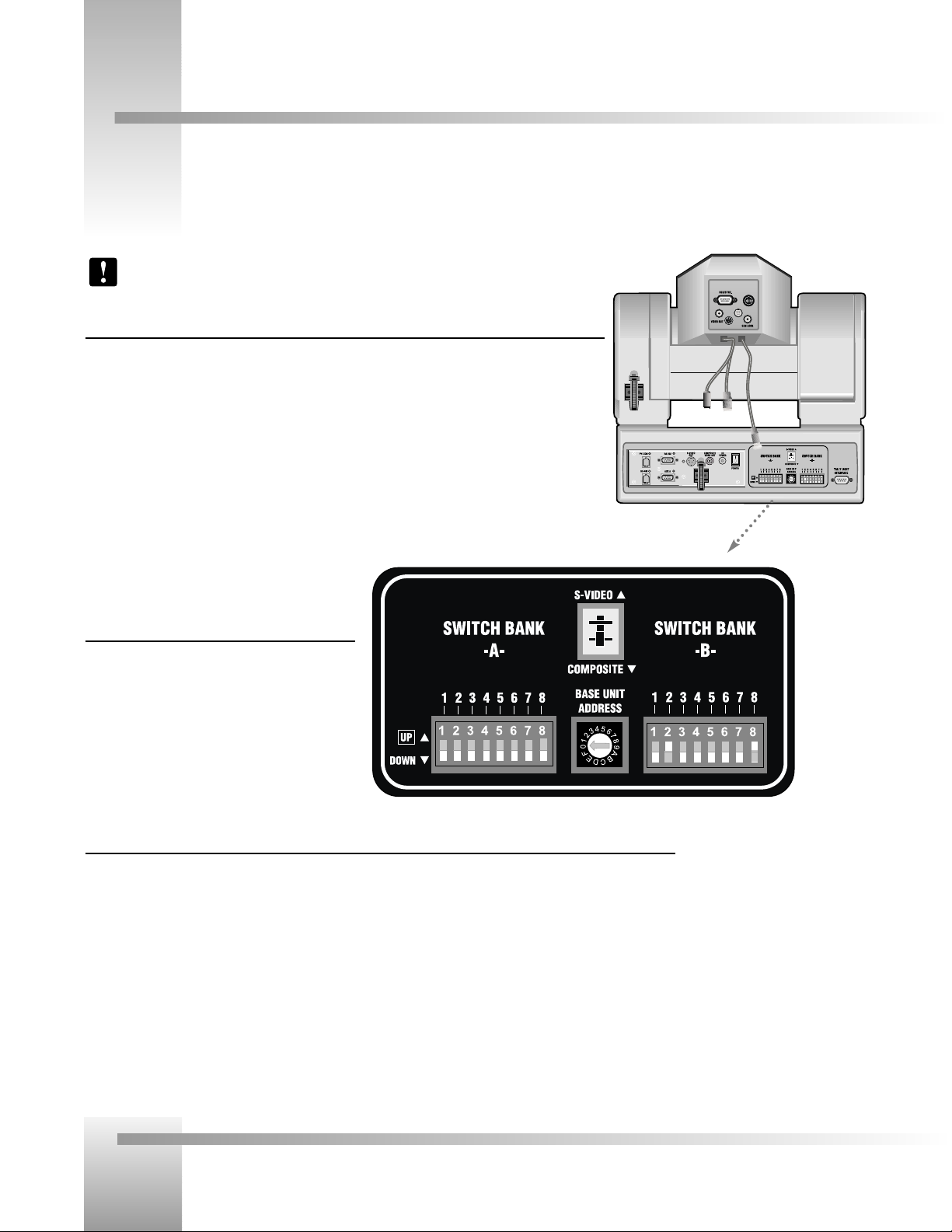
CameraMan Configuration Switches
Behind the configuration plate on the lower left side of the back of your CameraMan is the configuration panel. These DIP and
rotary switches allow you to link the camera’s settings to other components in your system.
Back of 3-CCD
CameraMan
Note: After changing any switch’s settings, turn the camera off, then back on to activate
the change.
Page 10

Page 7
Connect Your 3-CCD Camera System
Mounting Your CameraMan
You can mount your CameraMan Camera on any flat, non-slick, non-metal surface with a minimum supporting area of 8”x8” by
following these easy steps.
Step 1: Check your selected camera-location to ensure that you have enough camera and
cable clearance space (right) for the CameraMan to pan and tilt without
obstruction.
Note: Do not mount the camera upside down, or with more than a 10°
angle from horizontal.
Tip: See Appendix E: FIELD OF VIEW SPECIFICATIONS on page 18, to
assist in placing the CameraMan to achieve optimum optical views.
Step 2: Locate the zero-degree position mark labeled FRONT on the bottom of the base
unit. This mark helps ensure that the base unit is calibrated correctly. Point this
indicator mark in the direction that best reflects the center of travel in which the
camera will be used (usually the center of the room).
Step 3: To ensure that your camera-mounting is not prone to vibrations, securely fasten
the camera to a rigid flat surface using a 1/4"-20 UNC cap screw that does not
extend into the base platform by more than 0.4". (The screw hole is provided in
the base platform for this purpose. The cap screw is not provided.) This screw
should be hand-tightened. If necessary, use a non-hardening threadlock to prevent
the screw from loosening.
Note: Be sure to take environmental conditions into consideration when
operating the camera. Always operate the camera indoors, and follow
the temperature and humidity specifications outlined in Appendix C:
CAMERA SPECIFICATIONS on page 16.
Zero degree
position mark
1/4”-20 UNC Mounting
Screw Hole
Diameter
Page 11

Page 8
CameraMan®3-CCD Camera System Installation and Operations Manual
Connecting To The Camera System
On page five, you learned where the CameraMan’s video and network connection ports and jacks are located. Now, you can begin
connecting the camera to your system..
Tip: After connecting each cable to the camera, let it hang loosely behind the camera.
Then follow the instructions in the “Restraining the Cable Connections” section before
attaching the other ends of the cable to other equipment. This will relieve undue stress
on the cables, allowing the camera to move freely.
Connecting The Camera Control Cables
On the back of the camera, you’ll notice three cables. These control the camera’s lens, power
and video signals. These must be attached for the camera to operate properly.
• Connect the 8-pin male connector (#1) to the middle female jack.
• Connect the 12-pin female connector (#2) to the left male jack.
• Connect the 20-pin female connector (#3) to the right male jack.
Connecting The Video Output (on connector box)
The 3-CCD General Pan/Tilt Camera System supports NTSC and PAL versions (dependent on your
camera-type) of both Composite and S-Video formats, although only one can be used at a time.
For Composite format, connect to the BNC jack on the back of the camera, labeled
COMPOSITE VIDEO OUT, using a standard coaxial cable with a BNC connector (not provided).
Note: Verify that the Video Select switch is set to COMPOSITE on the back of the
General Pan/Tilt camera. (See Page 12)
Note: Only connect one signal output (composite or S-Video) at a time.
For S-Video format, connect to the S-VIDEO jack on the back of the camera, labeled
S-VIDEO, using a standard S-video cable (not provided).
Note: Verify that the Video Select switch is set to S-VIDEO on the back of the General
Pan/Tilt camera. (See Page 12)
Tip: For video output specifications, see Appendix C: CAMERA SPECIFICATIONS on page 16.
1
2
3
2 31
S-Video and Composite
Video Out Jacks
Page 12

Page 9
Connect Your 3-CCD Camera System
Connecting To The Camera System
Connecting The Video, RGB/Sync and Genlock Output (if needed)
RGB / SYNC: If your system requires RGB or component video output, use a DB9 to BNC
breakout cable to connect the DB-9 port labeled RGB / SYNC to an appropriate video input on
your network. The DB-9 pin assignments are:
Pin 1 Signal Pin 2 Ground (VBS)
Pin 3 RED (R-Y) output Pin 4 GREEN output
Pin 5 BLUE (B-Y) output Pin 6 VBS (Y) output
Pin 7 SYNC output Pin 8 Ground (SYNC)
Pin 9 NC (C output)
VIDEO OUT: For aux composite video output, connect the BNC-type connector labeled
“VIDEO OUT” to an alternate video input in your network using a standard BNC cable.
GEN LOCK: Connect the BNC-type connector labeled “GEN LOCK” to your network’s Video
Timing Source (Sync Generator) using a standard BNC cable.
Note: A Camera Control Keypad, Tracking System Keypad, or CameraMan Shot
Director are necessary to adjust the H. (horizontal) and SC (sub-carrier) phases, as well
as configure the RGB/Sync Connection.
Connecting To The RS-232 Port
The General Pan/Tilt Camera System provides for RS-232 communications using the DB-9 jack
on the back of the camera, labeled RS-232. This RS-232 port can be used to control the
CameraMan Camera from external devices such as a PC or other vendor control system (i.e.:
AMX, Crestron). Connect to this port using a standard computer cable with a DB-9 connector.
When used with a CameraMan SHOT Director, this port operates at 19,200 Baud, No Parity
and software hand-shaking using a High Reliability protocol. Otherwise, the port
operates at 9600 Baud, No Parity, and software hand-shaking using a High
Reliability or Basic protocols.
Note: Verify which protocol is being used by checking the PROTOCOL switch on the
Camera (see page 12).
Tip: The COM light above the RS-232 port is used to indicate communication activity.
Tip: For the DB-9 pinout port information, see the Appendix D: PIN-OUT DIAGRAMS
on page 17 .
RS-232 Port on the back of the
3-CCD CameraMan
Back of 3-CCD Camera Shroud
Page 13

Page 10
CameraMan®3-CCD Camera System Installation and Operations Manual
Connecting Camera Control Devices
There are several ways to control your CameraMan’s movement. The information below explains how to connect and configure the
optional Camera Control Keypad, or the CameraMan Shot Director .
Connecting Optional Camera Control Devices
Note: Do not use the Camera Control Keypad and the CameraMan SHOT Director at
the same time
Camera Control Keypad (or Tracking System Keypad)
The optional Camera Control Keypad controls the camera’s movement via wireless RF
technology (up to 60 feet), or hard-wired connection (up to 250 feet). If you choose to use a
Camera Control Keypad in the hard-wired mode, follow these directions for installation.
1. Using the 25’ CameraMan Keypad Cable included with your camera, connect one end
of the cable to the RJ-11 type jack located in the battery compartment of the keypad.
2. Connect the other end of the cable to the RJ-11 type jack on the back of the camera,
labeled PVI COM.
Tip: When the system is powered on, the light on the keypad should illuminate
momentarily, indicating the keypad is ready for operation. The light located above
the PVI COM port is used to indicate communication activity.
Note: Using cable other than the supplied cable for the PVI COM port may
cause damage.
CameraMan Shot Director
The optional Shot Director multi-camera controller can be connected in hard-wired mode only.
Follow these directions to connect the Shot Director to your CameraMan.
1. Using a standard RS-485 cable, connect one end of the cable to one of the RS-485
jacks (either one) on the back of the Shot Director.
2. Connect the other end of the cable to:
• The jack labeled RS-485 on the back of the CameraMan connector box for
single camera applications, or
• The T-Connector for multiple-camera applications. Then use the provided 3’
CameraMan Communication Cable to connect the T-connector to
the camera’s RS-485 jack.
Note: If you are using a Camera Control Keypad or Shot Director, you
should have its operations manual. If you do not, contact your local
reseller or Grass Valley.
CameraMan Shot Director
connected via RS-485
Camera Control
Keypad connected
via PVI COM
Page 14

Page 11
Connect Your 3-CCD Camera System
Restraining The Cable Connections
For upper (ie GEN LOCK) cable connections (if used)
1. Locate the cable restraint on the back left side of the camera.
2. Insert cable(s) through the cable restraint from left to right,.
Note: Allow 16” of cable between the restraint and the connection port to
provide enough slack for the camera’s tilting movement.
3. Tighten the restraint by pulling on the strap’s “free” end to prevent any cable from
becoming dislodged. (the cable restraint is reusable and adjustable)
4. Group the cables with all the other cables connected to the connector box and follow
the instructions below to feed them through the lower cable restraint.
For lower cable connections
1. Insert all cables (upper and lower) through the cable restraint from left to right.
This will result in the cables being located approximately in the center of the camera,
instead of near the edge.
2. Tighten the restraint by pulling on the strap’s “free” end to prevent any cable from
becoming dislodged.
Note: To relieve undue stress on the camera and the cable connections, it is
important to fasten all cables using the cable restrainer on the back of the
camera.
Note: Be sure to leave enough slack in the cables for the camera to pan left
and right free of any constraints.
Connecting The Power Supply
You can mount the Power Supply with any orientation, or on top of a table or roll-about unit
by using the following steps.
1. Verify that the POWER switch, on the back of the camera, is turned OFF.
2. Plug the 5.5mm female connector from the power supply cord into the DC POWER
jack in the back of the camera.
3. Connect the other end of the power supply into a 120 VAC source.
Feed the upper cables from left to right through the upper cable
restraint, then bundle with the lower cables and feed left to right
through the lower restraint.
Cable Restraint and System Power
You’ll notice that if left alone, the now connected cables may impede on the camera’s movement. To combat this, your 3-CCD
camera comes equipped with two cable restrainers on the left back, and on the connector box. Follow the instructions below to
properly restrain the cables and power-up the camera.
Power Connections and
Switches
Page 15
Page 12
CameraMan®3-CCD Camera System Installation and Operations Manual
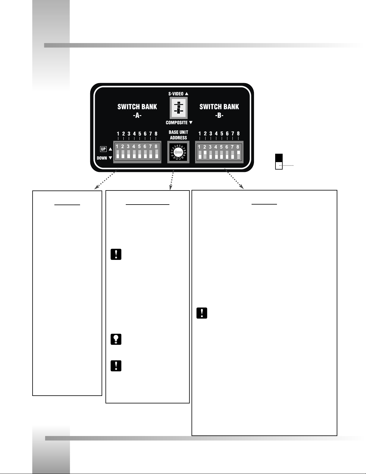
Switch Configuration
Now that you have connected your CameraMan to your power supply and control devices, you need to configure the camera to
work in your specific application. To begin, remove the configuration plate on the back right side of the camera by removing the
two screws holding it in place. Behind it, you’ll see all the configuration switches. From left to right, they are:
Switch Bank B
Dip Switch 1 (Protocol)
Select the communication protocol which will be used by the RS-232 and RS-485
ports on the camera. The High Reliability protocol includes some advanced error
checking that is not performed in the Basic protocol. (factory default: DOWN)
Dip Switch 2 (Camera Data Local/Remote Select)
When this switch is DOWN, the camera will receive data from a local source. When
it us UP, the camera will receive data from a remote source, such as a joystick.
(factory default: DOWN)
Dip Switch 4 (RF Command)
When this switch is DOWN, the camera responds to commands sent from an RF
Keypad. When it is UP, the RF receiver in the camera is disabled and the camera
cannot receive commands directly from a wireless keypad. (factory default: DOWN)
When using multiple cameras networked on the RS-485 bus, only one
camera should have its RF receiver enabled. Set switch 4 on the other
cameras to UP.
Dip Switch 5 (Preset Save)
Use this switch to determine how the preset settings will be saved. DOWN saves
your Manual Gain, Iris, and Focus settings. UP saves only the Auto settings for
presets and autoTRACK Views. (factory default: DOWN)
Dip Switch 8 (Interlink)
Use this feature in multi-camera applications. When it is DOWN, all commands will
be passed onto the RS-485 communication bus to the appropriate camera. For a
single-camera application, the setting of this switch does not matter. (factory
default: DOWN).
Switch Bank A
Dip Switch 2 (SC-Coarse)
This switch is used to configure the
SC-PHASE (coarse) to either 0°
(DOWN) or 180° (UP). (factory
default: DOWN)
Dip Switch 7 (Baud Rate)
This switch is used to configure the
camera’s Baud Rate for the RS-232
and RS-485 ports. Switch UP for
19,200 and DOWN for 9600. (factory
default: UP)
Dip Switch 8 (Memory)
For the majority of applications, this
switch should be set to UNLOCK (UP).
When DOWN, all programmed
features are locked and cannot be
overridden. (factory default: UP)
Central Control Switches
Video Select (Composite/S-Video)
Set the video source switch to the down
position to select the COMPOSITE VIDEO OUT
option, or up to select the S-VIDEO OUT
option.(Factory Default: COMPOSITE)
You must choose either the
Composite, or S-Video format. They
cannot be used simultaneously.
Base Unit Address
Use the 16-position rotary switch labeled BASE
UNIT ADDRESS to set the unique identification
number for this CameraMan. If using the
optional Keypad, Shot Director, or another
control system, refer to the documentation
provided with those accessories for proper
configuration.
For setting up a camera network,
see page 15, Appendix B: MULTIPLE
CAMERA APPLICATIONS.
All switches not discussed on this
page should remain in the down or
OFF position.
Example: Switch in
the down position
Page 16

Page 13
Use Your 3-CCD Camera System
System Startup
Once all necessary connections and configurations are made, you are ready to turn on the system.
Powering On
1. Just switch the Power button on the back of the CameraMan Camera to the ON position.
The Camera should automatically enter its position calibration mode and then stop at the
zero degree point.
2. Verify that the camera is now facing in the direction the "FRONT" label was pointing during
mounting (see page 7).
3. If you are using the optional Camera Control Keypad or Shot Director, make sure its base
unit address is the same as on the camera. If they are, verify that the camera’s PAN and
TILT functions are working properly.
Tip: If the camera does not move, refer to the TROUBLESHOOTING section
ofyour Camera Control Keypad, or Shot Director manual.
Back of CameraMan with
power supply
Page 17

Page 14
CameraMan®3-CCD Camera System Installation and Operations Manual
Appendix A: Troubleshooting
Problem: The Camera’s Video is not working properly.
Solution: 1. Verify that the VIDEO SELECT switch on the back of the
Camera is set properly. (see page 12)
2. Verify that the appropriate video connection is
being used on the back of the camera, either
S-VIDEO or COMPOSITE VIDEO OUT. (see page 8)
3. Verify that the video output of the camera is connected to the
appropriate video input on the switcher or CODEC.
Problem: No communications through the RS-232 port.
Solution: 1. Verify that the cable being used is wired correctly. (see page 17)
2. Verify that the PROTOCOL SELECT switch on the back of
the Camera is set properly. (see page 12)
3. Verify that the BASE UNIT ADDRESS switch is set properly.
4. Does the COM light above the RS-232 port on the back of
the camera blink when you send a command through this
port? If no, change the cable and retry.
Back of 3-CCD CameraMan
COM light on
RS-232
Connection
Should you have any problems with your CameraMan General Pan/Tilt Camera System, please refer to the following guide. If you
still have questions or problems after troubleshooting, please contact your authorized reseller or contact Grass Valley.
Page 18

Page 15
Appendices
Appendix B: Multi-Camera Applications
If your application requires that you have more than one CameraMan, you will need to set them up in a “daisy-chain” network
conguration by following these steps:
1. Connect the cameras together by plugging the supplied T-connector into the
RS-485 port on the back of the camera.
2. Connect each camera using a 4-conductor cable, with 4-position modular handset plugs
wired "straight-through":
Pin 1...........Pin 1
Pin 2...........Pin 2
Pin 3...........Pin 3
Pin 4...........Pin 4
Note: Do NOT use a standard phone cable, as these are wired dierently and
may cause damage.
3. Using the BASE UNIT ADDRESS rotary switch, which is located on the back of the
Camera, congure each camera with a unique Base Unit Address.
(i.e.: Camera One would be set with address 0, Camera Two would be set with
address 1, and so on)
4. In order to control each camera with your Camera Control Keypad, the rotary switch
inside the keypad battery compartment must match the lowest Base Unit
Address in your system. For example, if the Base Unit Address switches are
set according to the illustration to the right, the rotary switch inside the
keypad should be set to zero. The Camera Control Keypad can control up
to three cameras.
Camera One
Camera Two
Connector T
Camera Three
Page 19

Page 16
CameraMan®3-CCD Camera System Installation and Operations Manual
3-CCD General Pan/Tilt Camera
Appendix C: Camera Specifications
Image Sensor: . . . . . . . . . .1/2"IT (Interline Transfer Power HAD) CCD (x3)
CCD Integration Mode: . . .Frame/Field Selectable
Picture Elements: . . . . . . . .NTSC: 768 (H) x 494 (V)
PAL: 752 (H) x 582 (V)
CPT-2013-A3N(A3P)
Lens (13x): . . . . . . . . . . . . . . . . .13x Zoom; f = 7.5 to 97.5 mm
Angle of View(13x Lens) . . . . . . .46.2° x 35.6° @ 7.5 mm
3.8° x 2.8° @ 97.5 mm
Minimum Rel. Aperture: . . . . . . .1:1.4 @ 7.5-80.3 mm
1:1.7 @ 97.5 mm
CPT-2018-A3N(A3P)
Lens (18x): . . . . . . . . . . . . . . . . .18x Zoom; f = 6.7 to 121 mm
Angle of View (18x Lens) . . . . . . .51.1° x 39.6° @ 6.7 mm
3.03° x 2.27° @ 121 mm
Minimum Rel. Aperture: . . . . . . .1:1.4 @ 6.7-91 mm
1:1.85 @ 121 mm
Hor. Resolution: . . . . . . . . . . . . .750 TV Lines
Min. Illumination: . . . . . . . . . . . .5 lux F1.4
Sensitivity: . . . . . . . . . . . . . . . . .NTSC: F9.5 at 2000 lux
PAL: F8.5 at 2000 lux
S/N Ratio: . . . . . . . . . . . . . . . . . .NTSC: 60 dB
PAL: 58 dB
Gamma Control: . . . . . . . . . . . . .ON/OFF Switchable
Gain Control: . . . . . . . . . . . . . . .AGC/0 to 18 dB Selectable
CCD Iris Control: . . . . . . . . . . . . .ON/OFF Selectable
White Balance: . . . . . . . . . . . . . .Auto/Manual (R/B Gain), ATW Selectable
Linear Matrix: . . . . . . . . . . . . . . .ON/OFF Switchable
Electronic Shutter
Speed (sec): . . . . . . . . . . . . . . . .NTSC: Adjustable in the range of 1/10,000 to
about 8.5 second.
PAL: Adjustable in the range of
1/10,000 to about 10 second.
Iris Control: . . . . . . . . . . . . . . . . .Auto or Manual
Mechanical Drives: . . . . . . . . . . .WhisperDRIVE Plus™ Rated For 5000 Hrs.
Of Continuous Motion
Tilt: . . . . . . . . . . . . . . . . . . . . . .± 25° (Speed: 1°/Sec to 50°/Sec)
Pan: . . . . . . . . . . . . . . . . . . . . . .359° (Speed: 1°/Sec to 45°/Sec)
Location Presets: . . . . . . . . . . . . .125
Location Preset Data . . . . . . . . . .Pan, Tilt, Zoom, Focus, Iris, Pedestal,
R/B Gain, R/B Paint
Location Preset Accuracy: . . . . . .±.125°
Video Out . . . . . . . . . . . . . . . . . .NTSC or PAL
Connector Type . . . . . . . . . . . . .Composite— 75 Ohm BNC (x2)
Y/C— 4-pin miniDIN
Y,U,V/RGB— 9-pin D (F)
Genlock— 75 Ohm
RS-232 Port: . . . . . . . . . . . . . . . .DB-9(F) Connector
RS-485 Port: . . . . . . . . . . . . . . . .Bus Up To 16 Cameras
(4 pos. RJ handset port)
Power: . . . . . . . . . . . . . . . . . . . .100-240VAC Power Supply
100 W Maximum Consumption
Genlock: . . . . . . . . . . . . . . . . . . .VBS lock (F range: 3.58Mhz+50Hz)
Phase Control: . . . . . . . . . . . . . .H/SC Phase Control
Knee: . . . . . . . . . . . . . . . . . . . . .Switchable
Scanning System: . . . . . . . . . . . .NTSC: 2:1 Interlaced, 525 Lines
PAL: 2:1 interlaced, 625 lines
Temperature . . . . . . . . . . . . . . . .32° to 100°F (0°-37.78° C)
Humidity: . . . . . . . . . . . . . . . . . .0 to 95% Non-condensing
Dimensions: . . . . . . . . . . . . . . . .US: 9.25"L x 12.75"W x 10.75"H
INT: 23.5cmL x 32.38cmW x 27.31cmH
CameraMan Clearance
The minimum dimension for the CameraMan is a circular diameter of 26”.
This accounts for both camera and cable clearance. Check cable movement
to avoid binding and stress on the camera.
Tip: See clearance diagram on page 7.
This device complies with part 15 of the FCC rules. Operation is subject to the condition that this device does not cause harmful
interference. FCC identifier: JFECM003-AA
Page 20

Page 17
Appendices
Appendix D: Pin-Out Diagrams
You’ll find the following pinout connections on the back of your connector box on the back of your CameraMan. These diagrams
are for your reference.
RS-485
Four position
Modular Handset
PVI COM
RJ-11
Pin Signal
1 12v
2 12v
3 Ground
4 Signal A
5 Signal B
6 Ground
RS-232
9-pin Female D-9 Sub
Pin Signal
2 Transmit
3 Receive
5 Ground
1,4,6-9 Not Used
Pin Signal
1 Ground
2 Signal A
3 Signal B
4 Ground
S-Video Connector
BNC Connector
+ 18v DC
Ground
Video (1Vpp)
C
Y
Y Ground
C Ground
Ground
5.5mm DC Power
Connector
Page 21

Page 18
CameraMan®3-CCD Camera System Installation and Operations Manual
Appendix E: Field-Of-View Specifications
The reference charts below represent the size of your field of view and angle of view from various distances and with different
lenses.
13x Lens:
Dist. from Lens No Zoom Full Zoom
(feet) Hor. (ft) Vert. (ft) Hor. (ft) Vert. (ft)
10 8.53 6.42 0.66 0.49
15 12.80 9.63 1.00 0.73
20 17.06 12.84 1.33 0.98
25 21.33 16.05 1.66 1.22
30 25.59 19.26 1.99 1.47
35 29.86 22.47 2.32 1.71
40 34.12 25.69 2.65 1.96
45 38.39 28.90 2.99 2.20
50 42.65 32.11 3.32 2.44
55 46.92 35.32 3.65 2.69
60 51.18 38.53 3.98 2.93
65 55.45 41.74 4.31 3.18
70 59.72 44.95 4.64 3.42
Angle of view 46.20° 35.60° 3.80° 2.80°
18x Lens:
Dist. from Lens No Zoom Full Zoom
(feet) Hor. (ft) Vert. (ft) Hor. (ft) Vert. (ft)
10 9.56 7.16 0.53 0.40
15 14.34 10.74 0.79 0.59
20 19.12 14.32 1.06 0.79
25 23.90 17.90 1.32 0.99
30 28.68 21.48 1.59 1.19
35 33.46 25.06 1.85 1.39
40 38.54 28.64 2.12 1.58
45 43.02 32.22 2.38 1.78
50 47.80 35.81 2.64 1.98
55 52.59 39.39 2.91 2.18
60 57.37 42.97 3.17 2.38
65 62.15 46.55 3.44 2.58
70 66.93 50.13 3.70 2.77
Angle of view 51.1° 39.4° 3.03° 2.27°
Example of distance’s
impact on field of view:
taken from Standard Lens
Table (10 feet and 20 feet)
Above- Vertical angle of view:
Below- Horizontal angle of view:
no zoom= wide angle (more scenery, less specific detail)
zoom= narrow angle (less scenery, more specific detail)
Page 22

Page 19
Appendices
Appendix F: Typical System Diagrams
Below is a typical setup for your CameraMan camera. The items in the diagram are not to scale.
choose one option
Page 23

Page 20
CameraMan®3-CCD Camera System Installation and Operations Manual
Appendix G: On-Screen Camera Menus
Your 3-CCD Camera allows you to adjust the camera settings via on-screen menus by using your Camera Control Keypad, or
CameraMan SHOT Director. These adjustments should be performed by qualified technical personnel only. The first menu is the
Exposure Setup Menu. If your system includes a SHOT Director, always use the SHOT Director’s LCD menus to make these
adjustments.
GAIN (video gain)
[AGC, STEP, ISO] Initial Setting: step, 0 dB, ISO, 400
AGC: Automatic control of video gain. The gain of the video
signal is automatically controlled depending on the
brightness of the subject.
STEP: Used to set the gain to a desired level from 0 to 18dB
in units of 1 dB.
ISO: Sets the video gain to the desired level in the ISO
sensitivity display (frame mode). The gain level can be
set to 400, 800, or 1600. In the field mode, the value
is twice the displayed value.
Note: CameraMan will automatically adjust gain when
using the IMAGE control from the keypad. The
adjustments above should only be made when special
conditions exist.
SHUTTER (electronic shutter) Initial Setting: off
The electronic shutter allows you to obtain blur-free pictures of a
fast moving subject.
OFF: Turns off the electronic shutter.
LONG EXP: Sets the shutter speed in units of 1 frame.
• Range: Field mode: 1-255 FRM (frames)
Frame mode: 2-256 FRM (frames)
• Sync/W.EN: This function lets you change the output
from the RGB/SYNC connector on the
rear panel. It is only enabled when the
unit is in the “long exp” mode.
• Booster: When camera is in “long exp” mode, this function lets you set the
focus or color for subjects in poor lighting conditions by allowing 4
frames accumulation and gain adjustment. In such situations, set
“booster” to on, set the focus and color, and then turn it off. You
can then shoot in long exposure mode.
• W.EN: Outputs a WEN (timing) pulse. Use this function to synchronize a
connected frame memory.
STEP: Allows setting the shutter to one of the following eight speeds:
FL, 1/125, 1/250, 1/500, 1/1000, 1/2000, 1/4000, and 1/10000 sec.
C.SCAN: Sets the shutter speed in units of 1 H (horizontal scanning time; 63.56µs). The
shutter speed can be set to anywhere between 1/525 - 260/525 H. This setting
can be used to reduce noise when shooting a computer screen.
CCD-IRIS: • ON: When an excessive amount of light passes through
the lens, this function increases the shutter speed
automatically. This has the same effect as reducing
the lens iris by six stops.
• OFF: Use this setting when shooting in normal lighting
conditions or when the following conditions exist:
• The picture flickers: This may occur with certain lighting
conditions. In such cases, set CCD IRIS to OFF and shutter speed
to FL.
• The CameraMan is used under fluorescent lighting. This may
slow variations in color to the picture. If the degree of color
variation is unacceptable, set CCD IRIS to OFF.
AE WINDOW [LARGE, MEDIUM, SPOT] Initial Setting: large
The AE (auto exposure) window comes in three different sizes and is used together with the
AGC and CCD-IRIS.
FIELD/FRAME [FIELD, FRAME] Initial Setting: field
FIELD: For shooting fast moving objects. The CCD accumulates and outputs the charges,
field by field, to give pictures showing a minimum blur even when the subject is
fast moving.
FRAME: For producing pictures with the highest possible vertical resolution. The CCD
accumulates and outputs the charges frame by frame.
Exposure Setup Menu
>1. Exposure Setup :A
Gain AGC
Shutter off
AE Window medium
Field/Frame field
Page 24

Page 21
Appendices
Appendix G: On-Screen Camera Menus
The second on-screen menu is the Color Setup.
C. TEMP (color temperature) Initial Setting: 3200K
• 3200K: for indoor shooting.
• 5600K: for outdoor shooting.
WHT. BAL (white balance)
[AUTO, MANU, ATW] Initial Setting: auto
AUTO: Set to autoWHITE value stored with the Auto White Balance button.
MANU: Manual adjustment of the white balance.
• R gain (red gain): -99 to 99
• B gain (blue gain): -99 to 99
ATW: Activates the auto-tracing white balance. This mode is used when light sources are
changing, as the white balance is automatically adjusted as the color temperature
changes.
PAINT: This is used to fine adjust the white balance in the ATW or Auto White mode.
• R PAINT (red paint): -7 to 7
• B PAINT (blue paint): -7 to 7
LINEAR MATRIX [ON, OFF] Initial Setting: on
Processes images with a color matrix to produce natural colors.
• ON: Matrix processing is activated
• OFF: Matrix processing is de-activated
SHADING [OFF, 1 TO 99] Initial Setting: off
In most situations, this should be set to OFF. It is used to compensate for uneven color
shading throughout the screen.
>2. Color Setup :A
C. Temp 3200K
WHT. Bal auto
R Paint off
G Paint off
Linear Matrix on
Shading off
Color Setup Menu
Page 25

Page 22
CameraMan®3-CCD Camera System Installation and Operations Manual
The third on-screen menu is the General Setup menu
M. PEDESTAL [-99 TO 99] Initial Setting: 00
• Normally set this to “00”.
• When the black parts of the picture are too dark, you can
brighten them by adjusting the master pedestal or black level.
Use of a waveform monitor is recommended.
DETAIL [-99 TO 99] Initial Setting: 00
This is used to adjust the sharpness of the outlines of objects in
the picture. A higher value makes the picture look sharper with
more detail on the image outlines, and a lower value makes the
picture look softer with less detail.
H. PHASE [-99 TO 99] Initial Setting: 00
When an external reference sync signal is connected to the GEN
LOCK connector on the back of the camera, the camera operates
at the frequency of that reference signal. The H. PHASE function
can be used to perfectly synchronize the horizontal phase of the
camera with the horizontal phase of the reference signal.
Note: If there is not an external sync signal connected,
no value is displayed.
SC PHASE [0, 180] and (SC)fine: [-99 to 99] Initial Setting: 00
When gen-locking the camera, use the SC PHASE and (SC)fine functions to adjust the
subcarrier phase. First use the SC PHASE for coarse adjustment and then (SC) fine for fine
adjustments. The subcarrier phase switch on the back of the camera (Switch Bank A-DIP Switch
2) must match the SC PHASE coarse adjustment.
Note: If there is not an external sync signal connected, no value is displayed.
GAMMA [ON, OFF] Initial Setting: on
• ON: For normal use of the camera. The camera compensates the reproduction
characteristics of the monitor CRT to produce natural tone images.
• OFF: The video signal is output linearly from the CCD without gamma compensation.
KNEE [1, 2] Initial Setting: 1
1- Use this setting for normal shooting conditions.
2- Use this setting when shooting a dark object and a highly illuminated
object at the same time.
G SYNC [ON, OFF] Initial Setting: on
• ON: Adds sync to the G signal output from the RGB/SYNC connector of the camera.
• OFF: The sync is separate from the G signal output at the RGB/SYNC connector of the
camera.
>3. General Setup :A
M. Pedestal 00
Detail 00
H. Phase 00
SC Phase 00
fine 00
Gamma on
Knee 1
G Sync on
Appendix G: On-Screen Camera Menus
General Setup Menu
Page 26

Page 23
Appendices
Appendix G: On-Screen Camera Menus
The fourth on-screen menu is the System Setup menu
MEM. BANK [A, B] Initial Setting: A
Two different sets of settings can be stored in the camera, and then switched between
depending on the shooting conditions. These are stored in memory bank “A” and memory
bank “B”. The selected memory bank is shown in the upper right hand corner of the menu.
MEM. PROTECT [ON, OFF] Initial Setting: off
Each memory bank can be protected by setting the MEM. PROTECT to ON. When the bank is
protected, the memory bank indicator will be flashing.
Note: The following items can be changed even if the memory bank is protected:
GAIN, SHUTTER, C. TEMP, WHT. BALANCE, MEM. BANK, MEM. PROTECT, DATA
SEND
DATA SEND [A --> B, B --> A] Initial Setting: A-->B
The camera settings can be copied from one memory bank to the other.
D-SUB OUT [VBS/YC, RGB/COMP] Initial Setting: VBS/RGB
VBS: Changes the output of the RGB/SYNC connector on the camera to VBS output.
YC: Changes the output of the RGB/SYNC connector on the camera to Y/C
(S-video) output.
RGB: Changes the output of the RGB/SYNC connector on the camera to RGB output.
COMP: Changes the output of the RGB/SYNC connector on the camera to Component
Video output.
BAUD RATE [9600, 4800, 2400, 1200] Initial Setting: 9600
Changes the baud rate of the REMOTE connector on the camera.
Note: This setting should always be set to 9600. Changing this setting may impact
the camera’s communication links.
FLASH [OFF, MASTER, SLAVE] Initial Setting: off
This should always be set to OFF.
PRINTER [ON, OFF] Initial Setting: off
This should always be set to OFF.
>4. System Setup :A
Mem. Bank A
Mem. Protect off
Data Send B->A
D-Sub out VBS
Component
Baud Rate 9600
Flash master
Printer Trig. off
System Startup Menu
Page 27

Page 24
CameraMan®3-CCD Camera System Installation and Operations Manual
Appendix H: The 18x Lens Shroud
The 18x verson of the 3-CCD CameraMan camera comes equipped with a rectangular lens shroud. The shroud helps to keep out
glares from light sources located on the sides of the camera.
Installing the Shroud
1. Locate the red dots on the top and bottom
of the shroud, and on the lens itself.
2. Align the red dot on the shroud with the
dot on the lens, then slide the shroud over
the lens.
3. Tighten the shroud in place using the bolt
attached to the shroud.
lens shroud
tightening screw
red alignment dots
camera lens
Page 28

 Loading...