

Student Camera System
1-CCD and 3-CCD
Installation and Operations Manual
071838800
JUNE 2005

Contacting Grass Valley
Copyright © Thomson Broadcast and Media Solutions All rights reserved.
Grass Valley Web Site
The www.thomsongrassvalley.com web site offers the fol-
lowing:
Online User Documentation — Current versions of product cat-
alogs, brochures, data sheets, ordering guides, planning
guides, manuals, and release notes in .pdf format can be
downloaded.
FAQ Database — Solutions to problems and troubleshooting
efforts can be found by searching our Frequently Asked
Questions (FAQ) database.
Software Downloads — Software updates, drivers, and patches
can be downloaded.
Region Voice Fax Address
North America (800) 547-8949
Support: 530-478-4148
Sales: (530) 478-3347
Support: (530) 478-3181
Grass Valley
P.O. Box 599000
Nevada City, CA
95959-7900 USA
Pacific Operations +852-2585-6688
Support: 852-2585-6579
+852-2802-2996
U.K., Asia, Middle East +44 1753 218 777 +44 1753 218 757
France +33 1 45 29 73 00
Germany, Europe +49 6150 104 782 +49 6150 104 223

071838800
June 2005 viii
List of Figures x
Meet Your Student System 1
Congratulations On Your Purchase 1
System Components 5
PRM Jacks and Switches 7
Install Your Student System 9
Mounting and Connecting the PRM 9
Configure Your Student System 13
Configuring the Presets and Switches 13
Setting Up the Camera Control Keypad 17
Use Your Student System 21
Changing and Recalling Location Presets 21
Table of Contents

ix CameraMan 1-CCD and 3-CCD Student Camera System Installation and Operations Manual
Appendix A
Troubleshooting 25
Appendix B
Specifications 29
Appendix C
Typical Student System Diagram 31
Appendix D
Warranty Information 33
Index 35

071838800
June 2005 x
Front of Programmable Response Module (PRM) 5
1-CCD Camera Control Keypad 6
Power Supply 6
Top View with Cables and Front View of “T” Connector 7
PRM Front Panel 7
PRM Rear Panel 8
PRM Connected to CameraMan 11
Close-Up of Student Using Press-to-Talk Microphone 14
DIP Switch Configuration 15
Keypad Battery Compartment 17
1-CCD and 3-CCD Keypads 21
Wide-Angle Group View 23
Student Zoom View 23
PRM Clearance 29
Typical Student System 31
List of Figures

xi CameraMan 1-CCD and 3-CCD Student Camera System Installation and Operations Manual

071838800
June 2005 1
Congratulations On Your Purchase
Your new CameraMan Student Camera System
takes the distance out of distance learning by combining the flexibility of your 1-CCD or 3-CCD CameraMan camera with distributed preset control.
This manual covers the connection, configuration
and use of your new Student Camera System. It is
designed to be used in conjunction with the Installation and Operations Manual that came with your
CameraMan General Pan/Tilt 1-CCD or 3-CCD
camera, and the included Camera Control Keypad
Operations Manual. If you have any questions
regarding the operation of the keypad, or the connection, configuration or use of the camera, refer to
that manual.
You’ll see four icons in this manual:
This icon alerts you to important instructions in the
operation and maintenance of your Student Camera
System.
Chapter 1
Meet Your Student System

Chapter 1
2 CameraMan 1-CCD and 3-CCD Student Camera System Installation and Operations Manual
This icon alerts you to tips or noteworthy suggestions in the operation, use or maintenance of your
Student Camera System.
This icon refers you to the 1-CCD General Pan/Tilt
Camera installations and operations manual that
came with your camera.
This icon refers you to the 1-CCD or 3-CCD Camera
Control Keypad installation and operations manual.
The terms Visibly Better, System II, IMAGE, WhisperDRIVE Plus and General Pan/Tilt Camera System, and Student Camera System are registered
trademarks of Grass Valley, Inc. in the United States
of America. The terms CameraMan and Grass Valley are registered logos in the United States of
America. Federal law prohibits any commercial use
of these registered trademarks and logos.
The manufacturer reserves the right to change
specifications and warranty at any time without
notice or obligation.
Refer all Warranty and Servicing to the Grass Valley
Consumer Center listed in the back of the manual
that came with your 1-CCD or 3-CCD camera.
No part of this manual may be copied or reproduced
without express written consent of Grass Valley, Inc.
1997 Grass Valley, Inc.
DURACELL is a registered trademark of Duracell,
Inc.
Product Description The CameraMan Student Camera System is a
robotic camera system with distributed preset control used in distance learning applications. This system gives each student the power to be instantly
identified by the camera with the touch of a locator
button on a microphone.
The Student Camera System can store up to 125
Location Presets, 33 of which are connected to the
Programmable Response Module. The 33 Student
Locations are accessible through the Low Profile

Meet Your Student System
CameraMan 1-CCD and 3-CCD Student Camera System Installation and Operations Manual 3
Microphones and the Camera Control Keypad. The
other 92 Location Presets are only accessible
through the Camera Control Keypad.
In standard distance learning rooms, the camera is
set to a wide-angle view of the classroom throughout the lesson. This makes it difficult for instructors
at the far-end to differentiate one student from the
next and determine exactly which student is speaking. With CameraMan, each individual student can
simply press the “My Turn” button on a microphone
when they want to speak. The camera will then pan,
tilt and zoom in on the individual student, magnifying
their image.
When the student is finished speaking, the student
simply releases the “My Turn” button and the camera returns to a wide-angle view of the classroom.
This allows instructors at the far-end to identify each
student individually and have face-to-face interaction. Building these one-on-one relationships will
enhance the overall learning process, making distance learning more responsive and effective.
Your Student Camera System should include
these components:
• One 1-CCD or 3-CCD Camera Control Keypad
• One Programmable Response Module
• One Programmable Response Module Power
Supply
• One 10’ CameraMan Communication Cable
• One CameraMan RS-485 Connector “T”
• One 3’ CameraMan Communication Cable
• One Student Camera System Operations Man-
ual
• One Camera Control Keypad Card (1CCD or
3CCD)

Chapter 1
4 CameraMan 1-CCD and 3-CCD Student Camera System Installation and Operations Manual
FCC Compliance
Information
This equipment has been tested and found to comply with the limits for Class A digital devices, pursuant to Part 15 of the FCC Rules. These limits are
designed to provide reasonable protection against
harmful interference when the equipment is operated in a commercial environment. This equipment
generates, uses, and can radiate radio frequency
energy and, if not installed and used in accordance
with this manual, may cause harmful interference to
radio communications. Operation of this equipment
in a residential area is likely to cause harmful interference in which case the user will be required to
correct the interference at their own expense.
This unit was tested with shielded cables on the
peripheral devices. Shielded cables must be used
with the unit to insure compliance.
Grass Valley is not responsible for any radio or TV
interference caused by unauthorized modifications
to this equipment. Such modifications could void the
user’s authority to operate the equipment.

Meet Your Student System
CameraMan 1-CCD and 3-CCD Student Camera System Installation and Operations Manual 5
System Components
Your Student Camera System includes a Programmable Response Module, Power Supply, a 1-CCD
or 3-CCD Camera Control Keypad, and connection
accessories. To set up your system, you will also
need an audio mixer and microphones which may
be purchased separately through Grass Valley.
Programmable
Response Module
FIGURE 1.1 Front of Programmable Response
Module (PRM)
The Programmable Response Module (PRM) is
designed to provide automated camera control of a
student camera in a classroom environment.
Through the use of “press-to-talk” microphones, the
camera can be automatically positioned on an individual student when they wish to speak.
Grass Valley’s Low Profile Microphones are recommended for better camera control. “Voice-activated”
microphones may pick up background noise and
cause unwanted camera motion.
The PRM works on a first-come, first-served basis,
so when two or more students activate their microphones at the same time, the first microphone activated will get control of the camera. Once a student
has activated the camera, all others are LOCKED
out, except the master override microphone. When
the student is finished speaking, the PRM will take
the next microphone in line. After all the microphones become inactive, the camera will return to a
wide-angle shot of the classroom. This can be customized and is stored in Location Preset #2.
Chapter 1
6 CameraMan 1-CCD and 3-CCD Student Camera System Installation and Operations Manual
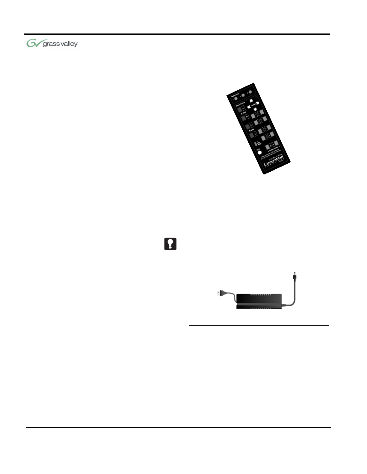
Camera Control Keypad
FIGURE 1.2 1-CCD Camera Control Keypad
The included Camera Control Keypad gives you the
ability to control the camera’s pan and tilt movement, focus, and IMAGE, as well as store and recall
up to 125 camera presets.
See the included Camera Control Keypad Operations Manual for information on setup, configuration
and use of the keypad.
Power Supply
FIGURE 1.3 Power Supply
The included Power Supply enables use with 120240VAC, 50/60 Hz sources.
Meet Your Student System
CameraMan 1-CCD and 3-CCD Student Camera System Installation and Operations Manual 7
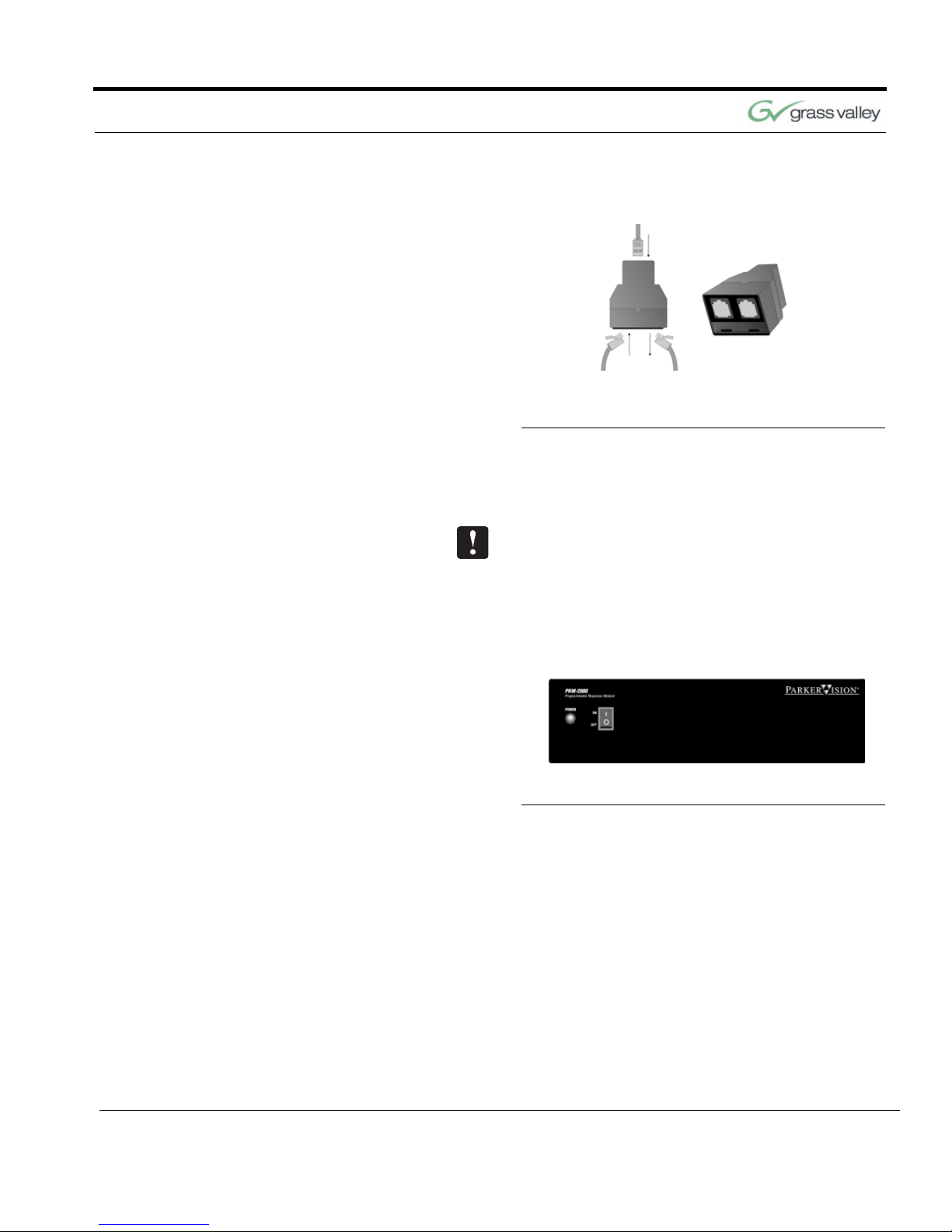
Connection Accessories
FIGURE 1.4 Top View with Cables and Front
View of “T” Connector
• 10’ RS-485 CameraMan Communication Cable
• CameraMan RS-485 “T” Connector
If you have purchased this as an upgrade, it will
include all components except the Camera.
PRM Jacks and Switches
FIGURE 1.5 PRM Front Panel
Power Switch Used to turn on power.
Power Indicator Light Inidicates power on/off status.

Chapter 1
8 CameraMan 1-CCD and 3-CCD Student Camera System Installation and Operations Manual
FIGURE 1.6 PRM Rear Panel
Inputs 1-31 Used for Normal Microphone Contact Closure
Inputs
Input 32 Used for Normal or Audio Only Microphone
Contact Closure Input.
Input 33 Used for Normal, Audio Only, or Master Override
Microphone Contact Closure Input.
Audio Relay When active, it activates the mute switch of the
audio system in the room to prevent feedback
when the microphone is active.
Video Relay When active, it activates a video switcher to allow
automated video switching.
RS-485 Jack Used to connect to your CameraMan Camera and
other Grass Valley devices. Used to network
multiple cameras.
DC Power Jack Used to supply power with the included Power
Supply.
Base Unit Address Switch 16-position rotary switch used to tell the PRM
which camera it controls. It should match the Base
Unit Address switch on the CameraMan camera.
The Factory Default is zero (0).
DIP Switches Used to configure the PRM’s camera and
microphone control.
RS-485 Inidcator Light Indicates communication activity.

071838800
June 2005 9
Mounting and Connecting the PRM
Now you can begin to connect your Student Camera
System components to your CameraMan camera,
and audio equipment.
Mounting the PRM 1. Mount or place the Programmable Response
Module in the desired location, being sure to
leave sufficient space to allow access to the connections on the back panel.
A rackmount is also available.
2. Verify that the switch on the front of the PRM is
turned OFF.
3. Mount or place the PRM power supply in a con-
venient location near the PRM.
4. Plug the connector from the power supply cord
into the DC POWER jack in the back of the
PRM.
5. Connect the other end of the power supply into a
100-240 VAC source.
Chapter 2
Install Your Student System
Chapter 2
10 CameraMan 1-CCD and 3-CCD Student Camera System Installation and Operations
The PRM Power Supply and CameraMan Power
Supply should not be interchanged.
Connecting Microphones
to the PRM
1. Place the microphones around the room, and
label them accordingly (i.e.: numbered 1, 2, 3,
etc.)
2. Connect the microphone via the appropriate
length microphone extension cable (not
included) to the optional microphone “Y” Cable
(5-pin mini XLR to 3-pin male XLR/2-pin female
Phoenix connector).
3. Connect 3-pin male XLR to your room’s micro-
phone mixer/phantom power source.
4. Connect the 2-pin female Phoenix Connector
(green connector block) to the appropriately
labeled PRM input (i.e.: 1, 2, 3, etc).
5. Repeat steps 2-4 for all remaining microphones.
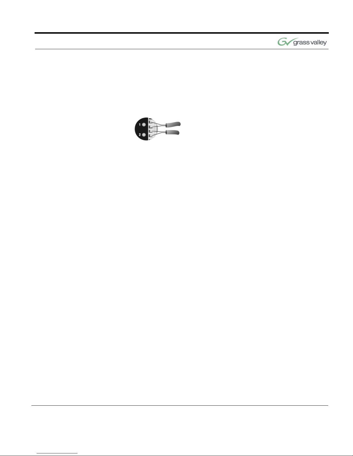
If you are using non-Grass Valley supplied “Y”
Cables, follow these instructions to connect the 2pin female Phoenix Connector wires to the green
connector block:
1. Strip a short section (approximately 0.15”) off the
end of the wire.
2. Insert the wire into the screw terminal slot on the
connector plug.
3. Tighten the terminal screw.
4. Repeat steps 1-3 for the other 4 wire-pairs in that
connector block.
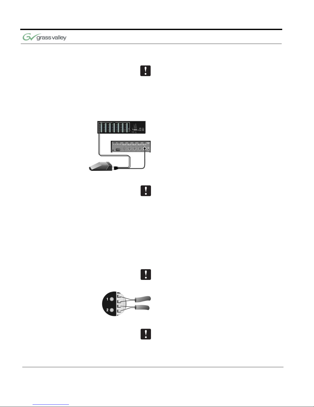
If you are using microphones which are polarity sensitive, the inputs should be wired as follows:
1. The positive lead, from the contact closure of the
microphone, should be wired to the top input of
the pair, labeled “+”.
2. The negative lead, from the contact closure of
the microphone, should be wired to the lower
input of the pair, labeled “-”.
All of the inputs labeled “-” are wired together internally and connected to ground.
Install Your Student System
CameraMan 1-CCD and 3-CCD Student Camera System Installation and Operations Manual 11
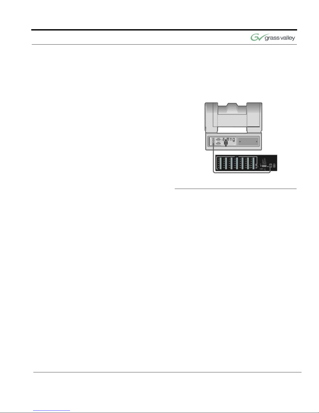
Connecting the PRM to
the CameraMan
Using a 4-conductor cable, wired in a “straightthrough” mode and terminated with modular handset connectors, connect the RS-485 port on the
back of the PRM to the RS-485 port on the back of
the CameraMan Camera.
FIGURE 2.1 PRM Connected to CameraMan
Connecting the Contact
Closure Outputs
The PRM’s AUDIO RELAY and VIDEO RELAY contact closure ouputs are activated when a “press-totalk” microphone button is pressed, and deactivated
when the button is pressed again.
AUDIO RELAY
The intended application of this relay is to activate
the mute switch of the audio system in the room to
prevent feedback when the microphone is active.
The relay activates and the contacts close only
when a microphone button is pressed. In a typical
application, the Audio Relay contact closure would
connect to an amplifier or audio switcher.
VIDEO RELAY
The intended application of this relay is to activate a
video switcher to select between various video
sources. The relay activates and the contacts close
only when a microphone button is pressed. When
the contact relay is closed, there is a two second
delay to allow time for camera movement before the
video is switched. In a typical application, the Video

Chapter 2
12 CameraMan 1-CCD and 3-CCD Student Camera System Installation and Operations
Relay contact closure would connect to a video
switcher.
To Connect the Audio, or Video Relay:
1. Connect one end of a 2-conductor cable to the
green connector block:
• Strip a short section (approximately 0.15”)
off the end of the wire
• Insert the wire into the AUDIO RELAY or
VIDEO RELAY screw terminal slot on the
connector block to the far right (the positive
“+” lead is on top, the negative “-” lead is
on the bottom
• Tighten the terminal screw
2. Connect the other end of the cable to your audio
equipment per their instructions.

071838800
June 2005 13
Configuring the Presets and Switches
Now that you’ve connected the Programmable
Response Module to your CameraMan and microphones, you can begin configuring the system. Use
the diagram and controls on the rear panel of the
PRM to perform this configuration.
Location Preset
Configuration
Your Student Camera System is capable of storing
and recalling 125 location presets. The included
Camera Control Keypad is used to store a pan and
tilt position, focus, zoom perspective, and IMAGE
control for each location preset. The microphones
and keypad are used to recall them.
Camera Preset # Preset Type Recalled By
1-31 normal press-to-talk button
32 normal/audio only (see p.7) press-to-talk button
33 normal/option (see p.7) press-to-talk button
72 default all other student mics deactivated
34-71 and 73-125 set by user keypad location preset buttons
Chapter 3
Configure Your Student System
Chapter 3
14 CameraMan 1-CCD and 3-CCD Student Camera System Installation and Operations
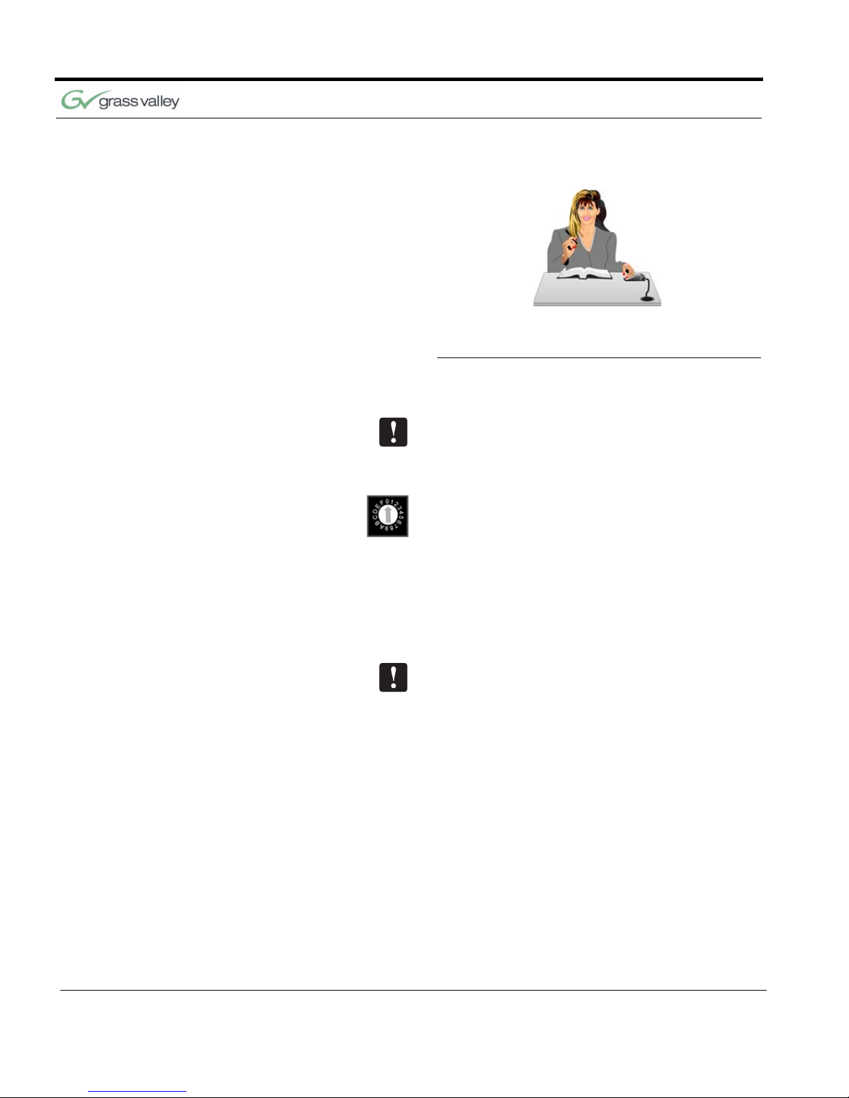
FIGURE 3.1 Close-Up of Student Using Press-
to-Talk Microphone
Configuring the PRM
The PRM POWER switch should be turned OFF
before changing any switches.
BASE UNIT ADDRESS:
This switch tells the PRM which camera it controls.
Set this switch to correspond with the BASE UNIT
ADDRESS switch on the back of the CameraMan
Student Camera (i.e.: If the camera’s BASE UNIT
ADDRESS is set to 0, set the PRM’s BASE UNIT
ADDRESS switch to 0). This address MUST BE different from the PRM Address.
PRM ADDRESS:
This switch is only accessible by removing the top
panel of the PRM. It is used to set the address at
which the PRM will reside on the RS-485 bus. This
should be set to an address that is unique to all
devices (cameras, PRMs, etc) in the system. By
default, the address is set to “C”. This address
MUST BE different from the Base Unit Address.
Configure Your Student System
CameraMan 1-CCD and 3-CCD Student Camera System Installation and Operations Manual 15
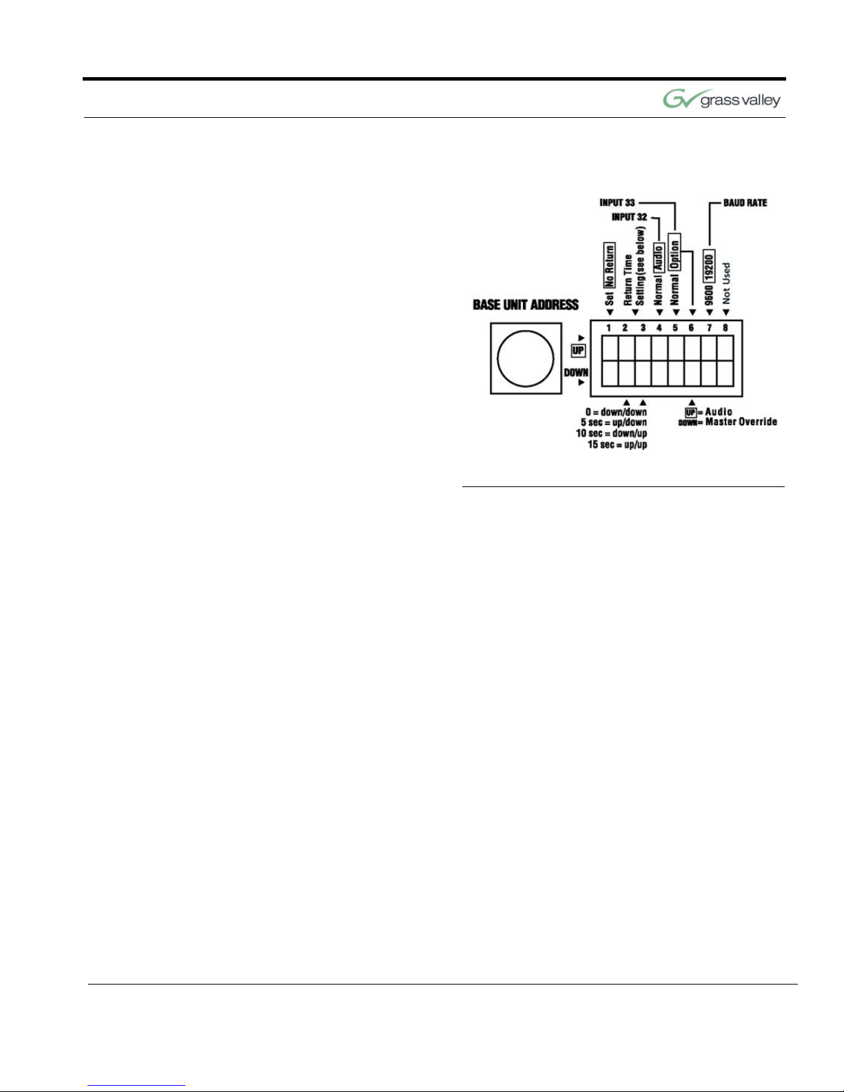
FIGURE 3.2 DIP Switch Configuration
SET/ NO RETURN (DIP Switch 1):
• DOWN (and all microphone inputs are inactive) -
The camera will return to a default preset (preset
# 72), which is usually set to be a wide shot of
the room.
• UP (and all microphone inputs are inactive) - The
camera will remain positioned at the last active
input.
RETURN TIME/ SETTING (DIP Switches 2,3):
• Switches 2 and 3 only apply if Switch 1 is set to
DOWN. They select the time delay associated
with the camera returning to the default preset
after the last active microphone is released.
• Use this chart to set the switches accordingly:
Switch 1 Switch 2 Switch 3 Time Delay
DOWN DOWN DOWN No Delay
DOWN UP DOWN 5 Second
DOWN DOWN UP 10 Second
DOWN UP UP 15 Second

Chapter 3
16 CameraMan 1-CCD and 3-CCD Student Camera System Installation and Operations
INPUT #32 OPERATION (DIP Switch 4):
This switch is used to determine the operation mode
of input 32.
• NORMAL - The input will operate as a
normal input, identical to inputs 1-31.
• AUDIO - The input will operate in an audio-
only mode, which causes no camera
movement when the microphone is active.
In audio-only mode, an active input will not
cause the VIDEO RELAY to be activated.
The audio-only mode is intended for use by someone who wishes to be heard, but does not want to
cause the camera to position on them, such as a
room facilitator.
INPUT #33 (DIP Switches 5,6)
Switch 5 is used to determine the operation mode of
input 33.
• NORMAL - The input will operate as a
normal input, identical to inputs 1-31.
• OPTION - Then the operation is dependent
upon the setting of DIP Switch 6.
Switch 6 settings
• UP - The input will operate in an audio-only
mode, which causes no camera movement
when the microphone is active. When in
audio-only mode, and active input will not
cause VIDEO RELAY to be activated.
• DOWN - The input will operate as a Master
Override input. When this input is active,
the camera will be positioned to a Master
Override position (preset 33) and all other
microphones will be “LOCKED” out from
controlling the camera. Once this input is
released, control is returned to all
microphones and they are serviced as
usual. In this case, the video relay will
remain open.
Configure Your Student System
CameraMan 1-CCD and 3-CCD Student Camera System Installation and Operations Manual 17
BAUD RATE SETTING (DIP Switch 7):
This switch determines the communication baud
rate: UP = 19,200; DOWN = 9,600
19,200 must be used if a SHOT Director or CameraMan Control Center is connected to the system.
DIP Switch 8:
Not in use at this time.
Setting Up the Camera Control Keypad
Your Camera Control Keypad is designed to be
used in either a wireless, or hard-wired mode. The
wireless mode allows you to move freely about the
room, while the hard-wired option gives you the ability to control the camera from greater distances. For
either, follow the next steps to prepare your keypad
for use with your Student Camera System.
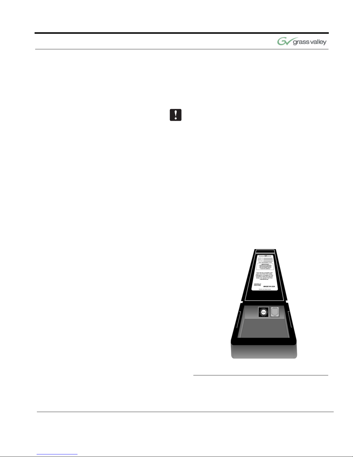
FIGURE 3.3 Keypad Battery Compartment

Chapter 3
18 CameraMan 1-CCD and 3-CCD Student Camera System Installation and Operations
Step 1 Adjust the KEYPAD ADDRESS rotary switch
(located in the battery compartment of the keypad)
so the selected setting corresponds to the setting of
the BASE UNIT ADDRESS switch on the back of
the Camera, and the front of the PRM.
See Also: For information on how to set the Base
Unit Address on your CameraMan camera, refer to
the CameraMan’s installation and operations manual.
Step 2 Connect the Keypad to meet your needs.
For Wireless RF Mode (up to 60 feet):
• Install the supplied AA batteries in the Camera
Control Keypad by removing the battery door
and inserting the battery into the battery compartment as indicated.
• Replace the battery door.
• Press one of the PAN/TILT arrows on the keypad
and verify that the LED on the front of the keypad
illuminates. This indicates that the battery is
installed properly.
Note: If the light does not illuminate, the battery may
be installed backwards. Reverse the way the battery
is inserted, and try again. If a low battery is installed,
the keypad will emit a long beep.
Note: If the battery is inserted improperly, it will not
damage the keypad. The keypad will simply not
work.
For Hard-wired Mode (up to 250 feet):
• Remove the batteries.
• Connect a CameraMan Keypad Cable (included)
to the RJ-11 type jack located in the battery compartment of the Keypad.
• Connect the other end of the cable to the PVI
Com port on the CameraMan base unit.
Note: When the system is powered on, the light on
the keypad should illuminate momentarily, indicating

Configure Your Student System
CameraMan 1-CCD and 3-CCD Student Camera System Installation and Operations Manual 19
the keypad is ready for operation. The light located
above the PVI COM port on the base unit is used to
indicate communication activity.
Note: You MUST remove the batteries in the Camera Control Keypad when it is being used in the
hard-wired mode.

Chapter 3
20 CameraMan 1-CCD and 3-CCD Student Camera System Installation and Operations
This page was intentionally left blank.

071838800
June 2005 21
Changing and Recalling Location Presets
Now that you’ve connected and configured your Student Camera System, you are ready to begin using
the system. To start, plug in the PRM, CameraMan,
and any other audio or video components in your
system, and power them up.
Using the Camera
Control Keypad
The Camera Control Keypad included with you Student Camera System comes in a 1-CCD or 3-CCD
version.
FIGURE 3.1 1-CCD and 3-CCD Keypads
Chapter 4
Use Your Student System

Chapter 4
22 CameraMan 1-CCD and 3-CCD Student Camera System Installation and Operations
For information on the specific features of your system’s Keypad Controller, refer to the included Keypad operations manual.
Both versions of the Keypad include the following
control features:
To Set or Change a
Student Location
1. Select the camera you want to program using
the CAMERA SELECT buttons. (If only using
one camera, be sure CAMERA SELECT 1 is
pressed.)
2. Use the PAN/TILT arrows to move the camera to
the desired location.
3. Only when desired, use the manual ZOOM but-
tons to set the needed Zoom perspective.
4. Only when desired, use the manual IMAGE but-
tons to set the needed light/dark contrast.
5. Input the Location Preset number (1-33) that cor-
responds with the PRM inputs.
6. Then press and hold the ENTER button until you
hear two beeps. The two beeps indicate the
Location Preset has been stored.
Camera Select Buttons Used to select which camera the keypad will
control.
Zoom IN and OUT Used to tighten and widen the on-screen image.
Pan/Tilt Arrows Used to move the camera left and right, up and
down.
IMAGE Controls Used to manually brighten (sun icon) and darken
(moon icon) the on-screen image.
Location Preset Buttons Used to select all Location Presets (1-125)
Enter Button Used to store and recall Location Presets. When
recalling Location Presets, it is selected AFTER
pressing the desired Location Preset Buttons.

Use Your Student System
CameraMan 1-CCD and 3-CCD Student Camera System Installation and Operations Manual 23
To Set the Wide-Angle
Group View
FIGURE 3.2 Wide-Angle Group View
1. Follow previously listed steps 1-4 to achieve a
wide-angle view.
2. Input Location Preset Number 72 to be the
default preset.
3. Then press and hold the ENTER button until you
hear two beeps. The two beeps indicate the
GROUP View has been stored.
To Recall a Student
Location
FIGURE 3.3 Student Zoom View
When a student wishes to speak, the student simply
presses the “My Turn” button on the microphone
and the CameraMan Camera will pan, tilt and zoom
in on that student, magnifying his or her image.
When the student is done speaking and the “My
Turn” button is released, the CameraMan Camera
will return to a wide-angle shot of the classroom
(preset 72).

Chapter 4
24 CameraMan 1-CCD and 3-CCD Student Camera System Installation and Operations
This page was intentionally left blank.

CameraMan 1-CCD and 3-CCD Student Camera System Installation and Operations Manual 25
APPENDIX A
Troubleshooting Should you have any problems with your Camera-
Man Student Camera System, please refer to the
following guide. After referring to the guide, should
you have any questions or problems, please contact
your authorized reseller, or contact Grass Valley.
Problem The Camera’s Video is not working properly.
Solution
1. Verify that the VIDEO SELECT switch on the
back of the Camera is set properly, either SVIDEO or COMPOSITE.
2. Verify that the appropriate video connection is
being used on the back of the camera, either SVIDEO or COMPOSITE VIDEO OUT. This is
determined by the VIDEO SELECT Switch.
Only one video source can be utilized at any one
time. Composite and S-Video formats cannot be
used simultaneously.
Problem The Camera Control Keypad will not control the
CameraMan Camera when used in the wireless
RF mode.
Solution 1. Verify that the battery is installed in the keypad
properly.
2. Verify that the BASE UNIT ADDRESS switch on
the back of the CameraMan Camera, and the
BASE UNIT ADDRESS switch in the battery
compartment of the keypad and on the PRM are
set to the same setting.
3. Verify the RF command switch on the back of the
CameraMan Camera is set to ENABLE. (B4
needs to be in the DOWN position).
4. Verify that the LED on the front of the Camera
Control Keypad illuminates for a few seconds
when the battery is first plugged in.
5. Be sure that you have pressed the appropriate
CAMERA SELECT button on the keypad corresponding to the camera you wish to control.

26 CameraMan 1-CCD and 3-CCD Student Camera System Installation and Operations Manual
Appendix A
If only using one camera be sure to press CAMERA
SELECT button 1.
Problem The Camera Control Keypad will not communi-
cate with the CameraMan Student Camera in the
“hard-wired” mode.
Solution 1. Verify that the CameraMan Keypad Cable is con-
nected from the PVI COM port on the back of the
camera to the RJ-11 jack in the battery compartment of the Keypad.
2. Does the light on the front of the keypad come
on for a few seconds when the keypad is first
plugged in? If not, replace cable with a Grass
Valley supplied cable only.
3. Be sure that you have pressed the appropriate
CAMERA SELECT button on the Keypad corresponding to the camera you wish to control.
If only using one camera be sure to press CAMERA
SELECT button 1.
Problem When a student microphone is activated, the
CameraMan Camera does not move.
Solution 1. Verify that the PRM POWER switch is ON.
2. Verify the microphone is wired to the correct
input on the PRM and that the corresponding
Location Preset is stored. Recall the location
with the Camera Control Keypad.
3. Verify that the BASE UNIT ADDRESS on the
back of the camera is set identically to the BASE
UNIT ADDRESS on the front of the PRM.
4. Verify that no microphones are “LOCKED”
active.
For information on locking and unlocking microphones, see Low Profile Microphone Manual.
5. Verify that the camera is not already at the
desired location.
6. Verify that the Baud Rate DIP switch #7 on the
front of the PRM matches the Baud Rate DIP
switch #A7 on the Base Unit. (DOWN=9600,
UP=19200).
CameraMan 1-CCD and 3-CCD Student Camera System Installation and Operations Manual 27
Troubleshooting
Problem The camera is locked on one microphone and
will not move when other “press-to-talk” buttons
are pressed.
Solution
Verify that the positive (+) and negative (-) leads on
the cable connecting that the microphones to the
PRM are lined up correctly with the contact closure
leads on the PRM.

28 CameraMan 1-CCD and 3-CCD Student Camera System Installation and Operations Manual
Appendix A
This page was intentionally left blank.
CameraMan 1-CCD and 3-CCD Student Camera System Installation and Operations Manual 29
APPENDIX B
Specifications Keypad RF Control Option
Hard-Wired Keypad Option
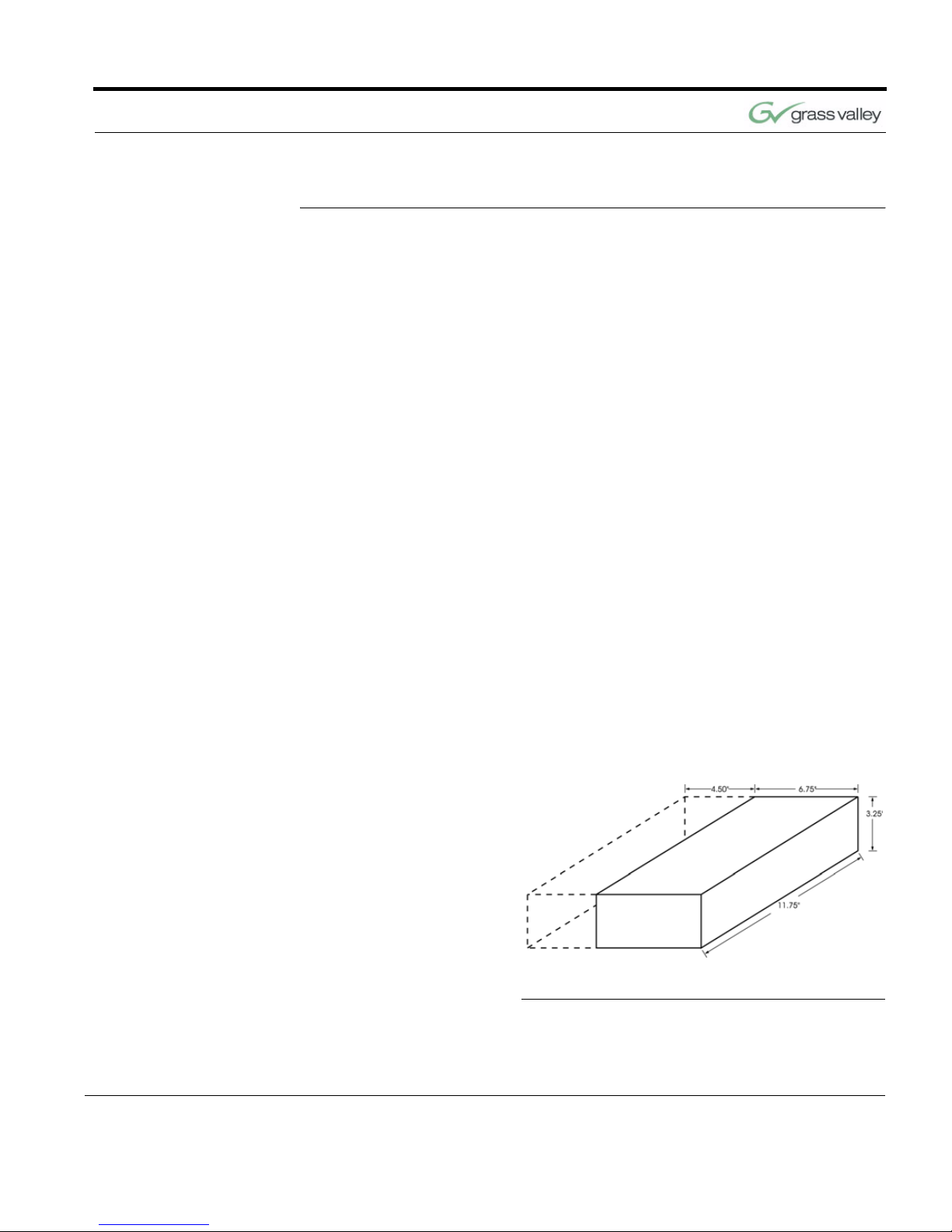
Programmable Response Module
FIGURE B.1 PRM Clearance
RF Range 60 ft. from Camera typical
Power (2) AA Batteries
Dimensions 7.0” L x 2.20” W x 0.85” H
Range 250 ft. from Camera typical
Power Supplied through cable
RS-485
Port
4-Pin Modular Jack
Power
Supply
100-240 VAC; 50-60Hz; 15 VDC
output; 100 W maximum
consumption
Humidity 0 to 95% non-condensing
Dimensions 11.75” L x 6.75” W x 3.25” H

30 CameraMan 1-CCD and 3-CCD Student Camera System Installation and Operations Manual
Appendix B
This page was intentionally left blank.
CameraMan 1-CCD and 3-CCD Student Camera System Installation and Operations Manual 31
APPENDIX C
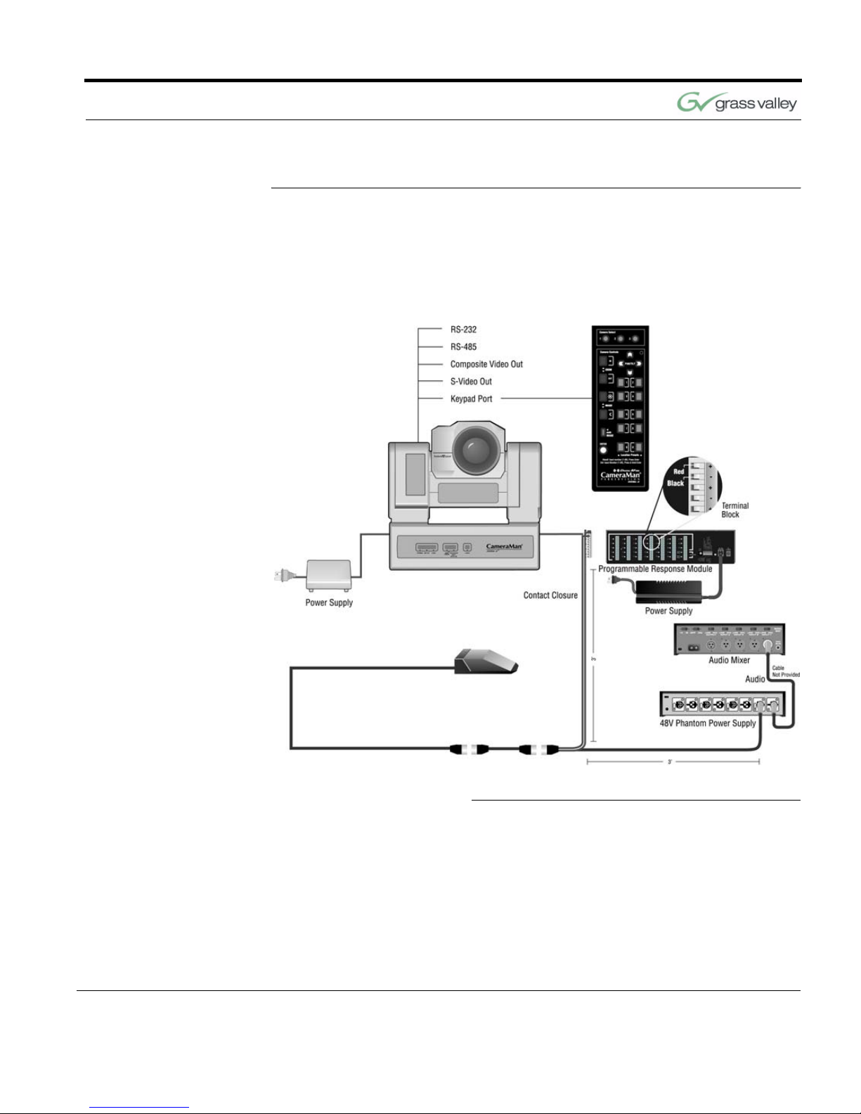
Typical Student System
Diagram
Below is a typical Student Camera System setup.
Your specific application needs, however, will determine how you set up your system.
FIGURE C.1 Typical Student System

32 CameraMan 1-CCD and 3-CCD Student Camera System Installation and Operations Manual
Appendix C
This page was intentionally left blank.

CameraMan 1-CCD and 3-CCD Student Camera System Installation and Operations Manual 33
APPENDIX D
Warranty Information
Grass Valley One-Year
Limited Warranty
•
Grass Valley warrants to the end user that
this product will be free from defects in
material and/or workmanship for a one-year
period commencing on the date of delivery,
except where expressly noted.
• Proof of Purchase: Grass Valley’s autho-
rized Dealer’s dated bill of sale must be
retained as evidence of the date of purchase and to establish warranty eligibility.
• Grass Valley will correct all defects in mate-
rial or workmanship, or any failure of the
system to perform to specifications during
the warranty period, at no charge for parts
and labor.
• The original purchaser must notify Grass
Valley, in writing, before the warranty period
has expired in the event of a defect in material or workmanship, or failure of the system
to perform to specifications.
• If damage occurs during shipment from the
Grass Valley factory, Grass Valley must be
notified within five working days of receipt of
the product in order to make a claim.
• Grass Valley is not obligated at any time to
provide the purchaser with a substitute unit.
• The warranty is not extended due to pur-
chasing new products and/or upgrading
your original product.
• The warranty is non-transferable.
• Purchaser’s failure to make a claim as pro-
vided above or continued use of the product
shall constitute an unqualified acceptance

34 CameraMan 1-CCD and 3-CCD Student Camera System Installation and Operations Manual
Appendix D
of such product and a waiver by purchaser
of all claims.
Product Warranty
Registration Form
• The warranty period begins the day your
Grass Valley product is received.
• Product Warranty Registration is required to
ensure your product receives prompt attention if warranty work is ever necessary.
Please see your product warranty registration form,
which is packaged with every product, for detail on
enrolling.
The Warranty is voided
if...
• The product is damaged in shipping other
than the original shipment from the Grass
Valley factory.
• The product is used outside of the specifi-
cations or operating guidelines, as outlined
in the Grass Valley product manuals.
• The product has sustained physical dam-
age from misuse or abuse.
• The product has sustained damage due to
a natural disaster such as fire, lightning,
earthquake, etc.
• The product is damaged by non-Grass Val-
ley peripherals.
• A person not authorized by Grass Valley
has attempted to/or has serviced the equipment.
• The product’s identification (serial numbers,
trademarks, etc.) is removed, defaced, or
altered.
Return Policies Contact your authorized Grass Valley Reseller for
return procedures.
Extended Service and
Support
For details on extended service and support, please
contact Grass Valley’s Customer Service Department.

071838800
June 2005 35
Index
A
About Manual, 1–2
B
BASE UNIT ADDRESS, 14
C
Camera Control Keypad, 6
setting up, 17–19
specifications, 29
using, 21–22
Components, 5–7
Configuring Presets, 13
Connection Accessories, 7
Contact Information, vi
M
Manual Overview, 1–2
Microphone
connecting, 10
P
Power Supply, 6
Preset Configuration, 13
Product Description, 2–3
Programmable Response
Module (PRM)
, 5
clearance, 29
configuring, 14–17
connecting CameraMan to, 11
connecting contact
closure outputs
to
, 11
connecting microphones to
, 10
jacks and
switches, 7–8
mounting, 9
specifications, 29
S
Specifications, 29
Student Location
recalling, 23
setting/changing, 22
Student System
changing and recalling location
presets
, 21–23
components, 5–7
description, 2–3

36 CameraMan 1-CCD and 3-CCD Student Camera System Installation and Operations Manual
Index
diagram, 31
preset
configuration
, 13
T
Troubleshooting, 25
W
Warranty, 33
Website, vi
Wide-Angle Group View, 23
 Loading...