

Page 1

CopperHead 3430AP
User Manual
4042-99M00-101
9 February 2015
Page 2

Copyright © 2015 by Grass Valley, A Belden Brand
All rights reserved. No part of this manual may be reproduced in any form by photocopy, microfilm, xerography or any other means, or incorporated into any information retrieval system,
electronic or mechanical, without the written permission of Grass Valley, A Belden Brand.
• Document revision: 101
• Document part number: 4042-99M00-101
Change History
Revision Published Description of Changes
4042-99M00-100 29 July 2014 Initial release
4042-99M00-101 9 February 2015 Correction of figure labels
Notice
Because of continued product development, the accuracy of the information in this document
may change without notice. The information and intellectual property contained herein is confidential between Grass Valley and the client and remains the exclusive property of Grass Valley. If
you find any problems in the documentation, please report them to us in writing. Grass Valley
does not warrant that this document is error-free.
Trademarks
Grass Valley is a registered trademark of Grass Valley, A Belden Brand.
Brand and product names mentioned in this manual may be trademarks, registered trademarks
or copyrights of their respective holders. All brand and product names mentioned in this
manual serve as comments or examples and are not to be understood as advertising for the
products or their manufacturers.
Software License Agreement and Warranty Information
Contact Grass Valley for details on the software license agreement and product warranty.
ii
Page 3
Safety Compliance
CopperHead 3430AP
User Manual
This equipment complies with:
• CSA/UL/IEC/EN 60950-1, 2nd Ed., for Information Technology Equipment -
Safety requirements
The power cord supplied with this equipment meets the appropriate national
standards for the country of destination.
WAR NIN G:
CAUTION:
An appropriately listed/certified mains power supply cord must be used
for the connection of the equipment to the mains voltage at either 120V~
or 240V~.
These servicing instructions are for use by qualified personnel only.
To reduce the risk of electric shock, do not perform any servicing other than that
contained in the operating instructions unless you are qualified to do so. Refer all
servicing to qualified service personnel.
Disconnect all power supplies before servicing.
Electromagnetic Compatibility
This equipment has been tested for verification of compliance with FCC Part 15,
Subpart B requirements for Class A digital devices.
NOTE: This equipment has been tested and found to comply with the limits for a Class A
digital device, pursuant to part 15 of the FCC Rules. These limits are designed to provide
reasonable protection against harmful interference when the equipment is operated in a
commercial environment. This equipment generates, uses, and can radiate radio frequency
energy and, if not installed and used in accordance with the instruction manual, may cause
harmful interference to radio communications. Operation of this equipment in a residential
area is likely to cause harmful interference in which case the user will be required to correct
the interference at his own expense.
iii
Page 4

This equipment has been tested and found to comply with the requirements of the
EMC directive 2004/108/CE:
• EN 55022 Conducted emissions, Class A
• EN 55022 Radiated emissions, Class A
• EN 61000-3-2 Harmonic current emission limits
• EN 61000-3-3 Voltage fluctuation and flicker limitations
• EN 61000-4-2 Electrostatic discharge immunity
• EN 61000-4-3 Radiated electromagnetic field immunity - RF
• EN 61000-4-4 EFT immunity
• EN 61000-4-5 Surge immunity
• EN 61000-4-6 Conducted immunity
• EN 61000-4-8 Power frequency magnetic field immunity
• EN 61000-4-11 Voltage dips, short-interruption and voltage variation immunity
Important Safeguards and Notices
This section provides important safety guidelines for operators and service personnel. Specific
warnings and cautions appear throughout the manual where they apply. Please read and follow
this important information, especially those instructions related to the risk of electric shock or
injury to persons.
[fr] Mesures de sécurité et avis importants
La présente section fournit des consignes de sécurité importantes pour les opérateurs et le
personnel de service. Des avertissements ou mises en garde spécifiques figurent dans le
manuel, dans les sections où ils s’appliquent. Prenez le temps de bien lire les consignes et
assurez-vous de les respecter, en particulier celles qui sont destinées à prévenir les décharges
électriques ou les blessures.
Symbols and Their Meanings
The lightning flash with arrowhead symbol within an equilateral triangle alerts the
user to the presence of dangerous voltages within the product’s enclosure that
may be of sufficient magnitude to constitute a risk of electric shock to persons.
The exclamation point within an equilateral triangle alerts the user to the
presence of important operating and maintenance/service instructions.
iv
Page 5
CopperHead 3430AP
User Manual
The earth ground symbol represents a protective grounding terminal. Such a
minal must be connected to earth ground prior to making any other
ter
connections to the equipment.
The fuse symbol indicates that th
with one having the ratings indicated.
The presence of this symbol in or on Grass V
been designed, tested and certified as complying with applicable Canadian
Standard Association (CSA) regulations and recommendations for USA/Canada.
The presence of this symbol in or on Grass V
been designed, tested and certified as complying with applicable Underwriters
Laboratory (UL) regulations and recommendations for USA/Canada.
The presence of this symbol in or on Grass V
been designed, tested and certified as essentially complying with all applicable
European Union (CE) directives.
The presence of this symbol in or on Grass
with safety of laser product applicable standards.
Safety of Laser Modules
This equipment incorporates modules containing Class 1 lasers. These modules
are certified by the manufacturer to comply with:
– IEC/EN 60825-1 Safety of laser products
– IEC 60950-1 Safety of information technology equipment
e fuse referenced in the text must be replaced
alley equipment means that it has
alley equipment means that it has
alley equipment means that it has
Valley product means that it complies
[fr] Sécurité laser
L’appareil comprend des modules laser de classe 1. Ces modules sont certifiés conformes
aux normes suivantes par le fabricant :
– IEC/EN 60825-1 Sécurité des appareils à laser
– IEC 60950-1 Sécurité du matériel informatique
Warnings
A warning indicates a possible hazard to personnel, which may cause injury or death.
Observe the following general warnings when using or working on this equipment:
• Appropriately listed/certified mains supply pow
the equipment to the mains voltage at either 120 V AC or 240 V AC.
• This product relies on the building's installation for short-circuit (over-current) protection.
e that a fuse or circuit breaker for 120 V AC or 240 V AC is used on the phase
Ensur
nductors.
co
er cords must be used for the connection of
v
Page 6

• Any instructions in this manual that require opening the equipment cover or enclosure are
for use by qualified service personnel only.
• Heed all warnings on the unit and in the operating instructions.
• Do not use this equipment in or near water.
• This equipment is grounded through the grounding conductor of the power cords. To avoid
electrical shock, plug the power cords into a properly wired receptacle before connecting
the equipment inputs or outputs.
• Route power cords and other cables so they are not likely to be damaged.
• Disconnect power before cleaning the equipment. Do not use liquid or aerosol cleaners;
use only a damp cloth.
• Dangerous voltages may exist at several points in this equipment. To avoid injury, do not
touch exposed connections and components while power is on.
• Do not wear rings or wristwatches when troubleshooting high current circuits such as the
power supplies.
• To avoid fire hazard, use only the specified fuses with the correct type number, voltage and
current ratings as referenced in the appropriate locations in the service instructions or on
the equipment. Always refer fuse replacements to qualified service personnel.
• To avoid explosion, do not operate this equipment in an explosive atmosphere.
• This product includes a backup battery. There is a danger of explosion if the battery is
replaced incorrectly. Replace the battery only with the same or equivalent type
recommended by the manufacturer. Dispose of used batteries according to the
manufacturer’s instructions. Before disposing of your Grass Valley equipment, please review
the Disposal and Recycling Information appendix.
• Have qualified service personnel perform safety checks after any service.
[fr] Avertissements
• Un cordon d’alimentation dûment homologué doit être utilisé pour connecter l’appareil à
une tension de secteur de 120
V CA ou 240 V CA.
• La protection de ce produit contre les courts-circuits (surintensités) dépend de l’installation
électrique du bâtiment. Assurez-vous qu'un fusible ou un disjoncteur pour 120
240
V CA est utilisé sur les conducteurs de phase.
V CA ou
• Dans le présent manuel, toutes les instructions qui nécessitent d’ouvrir le couvercle de
l’équipement sont destinées exclusivement au personnel technique qualifié.
• Respectez tous les avertissements figurant sur l’appareil et dans les instructions
d’utilisation.
• Ne pas utiliser cet appareil dans l’eau ou à proximité d’un point d’eau.
• Cet équipement est mis à la terre par le conducteur de mise à la terre des cordons
d’alimentation. Pour éviter les chocs électriques, branchez les cordons d’alimentation sur
une prise correctement câblée avant de brancher les entrées et sorties de l’équipement.
• Acheminez les cordons d’alimentation et autres câbles de façon à ce qu’ils ne risquent pas
d’être endommagés.
• Coupez l’alimentation avant de nettoyer l’équipement. Ne pas utiliser de nettoyants
liquides ou en aérosol. Utilisez uniquement un chiffon humide.
• Des tensions dangereuses peuvent exister en plusieurs points dans cet équipement. Pour
éviter toute blessure, ne touchez pas aux connexions ou aux composants exposés lorsque
l’appareil est sous tension.
vi
Page 7

CopperHead 3430AP
User Manual
• Avant de procéder à toute opération d’entretien ou de dépannage visant des circuits à
courant élevé (e.g., les blocs d’alimentation), enlevez tous vos bijoux (notamment vos
bagues et votre montre).
• Pour éviter tout risque d’incendie, utilisez uniquement les fusibles du type et du calibre
indiqués dans la documentation ou sur l’équipement. Confiez le remplacement de fusibles
au personnel technique qualifié.
• Ne pas utiliser cet appareil dans une atmosphère explosive.
• L’appareil renferme une pile. Pour réduire le risque d’explosion, vérifiez la polarité et ne
remplacez la pile que par une pile du même type, recommandée par le fabricant. Mettez les
piles usagées au rebut conformément aux directives du fabricant. Avant de vous défaire de
l’équipement, assurez-vous d’avoir lu l’appendice
• Après tout travail d’entretien ou de réparation, faites effectuer des contrôles de sécurité par
le personnel technique qualifié.
Disposal and Recycling Information.
Cautions
A caution indicates a possible hazard to equipment that could result in equipment
damage. Observe the following cautions when operating or working on this
equipment:
• When installing this equipment, do not attach the power cord to building surfaces.
• To reduce the risk of electric shock, do not perform any servicing other than that contained
in the operating instructions unless you are qualified to do so. Refer all servicing to qualified
service personnel. Servicing should be done in a static-free environment.
• To prevent damage to equipment when replacing fuses, locate and correct the problem
that caused the fuse to blow before re-applying power.
• Use only the specified replacement parts.
• Follow static precautions at all times when handling this equipment.
• Products that have no on/off switch, and use an external power supply must be installed in
proximity to a main power outlet that is easily accessible.
[fr] Mises en garde
• Au moment d’installer l’équipement, ne fixez pas les cordons d’alimentation aux surfaces
intérieures de l’édifice.
• Pour réduire le risque de choc électrique, n'effectuez pas de réparations autres que celles
qui sont décrites dans le présent manuel, sauf si vous êtes qualifié pour le faire. Confiez les
réparations à un technicien qualifié. La maintenance doit se réaliser dans un milieu libre
d’électricité statique.
• Pour éviter d'endommager l'équipement lors du remplacement de fusibles, localisez la
source de la panne et corrigez la situation avant de rétablir le courant.
• Employez uniquement les pièces de rechange recommandées par le fabricant.
• Veillez à toujours prendre les mesures de protection antistatique appropriées quand vous
manipulez l’équipement.
• Les produits qui n'ont pas d’interrupteur marche-arrêt et qui disposent d’une source
d’alimentation externe doivent être installés à proximité d'une prise de courant facile
d’accès.
vii
Page 8

Electrostatic Discharge (ESD) Protection
Electrostatic discharge occurs when electronic components are improperly handled
and can result in intermittent failure or complete damage adversely affecting an
electrical circuit. When you remove and replace any card from a frame always follow
ESD-prevention procedures:
• Ensure that the frame is electrically connected to earth ground through the power cord or
any other means if available.
• Wear an ESD wrist strap ensuring that it makes good skin contact. Connect the grounding
clip to an unpainted surface of the chassis frame to safely ground unwanted ESD voltages. If
no wrist strap is available, ground yourself by touching the unpainted metal part of the
chassis.
• For safety, periodically check the resistance value of the antistatic strap, which should be
between
• When temporarily storing a card make sure it is placed in an ESD bag.
• Cards in an earth grounded metal frame or casing do not require any special ESD
protection.
[fr] Protection contre les décharges électrostatiques (DES)
Une décharge électrostatique peut se produire lorsque des composants électroniques ne sont
pas manipulés de manière adéquate, ce qui peut entraîner des défaillances intermittentes ou
endommager irrémédiablement un circuit électrique. Au moment de remplacer une carte dans
un châssis, prenez toujours les mesures de protection antistatique appropriées
• Assurez-vous que le châssis est relié électriquement à la terre par le cordon d'alimentation
ou tout autre moyen disponible.
• Portez un bracelet antistatique et assurez-vous qu'il est bien en contact avec la peau.
Connectez la pince de masse à une surface non peinte du châssis pour détourner à la terre
toute tension électrostatique indésirable. En l’absence de bracelet antistatique, déchargez
l’électricité statique de votre corps en touchant une surface métallique non peinte du
châssis.
• Pour plus de sécurité, vérifiez périodiquement la valeur de résistance du bracelet
antistatique. Elle doit se situer entre 1 et 10 mégohms.
• Si vous devez mettre une carte de côté, assurez-vous de la ranger dans un sac protecteur
antistatique.
1 and 10 megohms.
:
viii
Les cartes qui sont reliées à un châssis ou boîtier métallique mis à la terre ne nécessitent pas de
protection antistatique spéciale.
Restriction on Hazardous Substances (RoHS)
Grass Valley is in compliance with EU Directive RoHS 2002/95/EC governing the restricted use of
certain hazardous substances and materials in products and in our manufacturing processes.
Grass Valley has a substantial program in place for RoHS compliance that includes significant
investment in our manufacturing process, and a migration of Grass Valley product electronic
components and structural materials to RoHS compliance.
Page 9

CopperHead 3430AP
User Manual
It is our objective at Grass Valley to maintain compliance with all relevant environmental and
product regulatory requirements. Detailed information on specific products or on the RoHS
program at Grass Valley is available from Grass Valley Customer Support.
ix
Page 10

x
Page 11

Table of Contents
1 Introduction . . . . . . . . . . . . . . . . . . . . . . . . . . . . . . . . . . . . . . . . . . . 1
The CopperHead 3430AP Fiber Optic Transceiver System . . . . . . . . . . . . . . . . . . . . . . . 1
Overview . . . . . . . . . . . . . . . . . . . . . . . . . . . . . . . . . . . . . . . . . . . . . . . . . . . . . . . . . . . . . . . . . . . . . . . . . 1
System Concepts . . . . . . . . . . . . . . . . . . . . . . . . . . . . . . . . . . . . . . . . . . . . . . . . . . . . . . . . . . . . . . . . . 2
2 Detailed System Description . . . . . . . . . . . . . . . . . . . . . . . . . . . . 3
CopperHead 3430AP Camera Unit . . . . . . . . . . . . . . . . . . . . . . . . . . . . . . . . . . . . . . . . . . . . . 3
Connectors, Indicators and Controls - Back Side . . . . . . . . . . . . . . . . . . . . . . . . . . . . . . . . . . . . 4
Connectors and Indicators - Front and Right Side . . . . . . . . . . . . . . . . . . . . . . . . . . . . . . . . . . 7
Controls and Indicators - Left Side . . . . . . . . . . . . . . . . . . . . . . . . . . . . . . . . . . . . . . . . . . . . . . . . . 9
Copperhead 3400 Base Station . . . . . . . . . . . . . . . . . . . . . . . . . . . . . . . . . . . . . . . . . . . . . . 14
Front Panel . . . . . . . . . . . . . . . . . . . . . . . . . . . . . . . . . . . . . . . . . . . . . . . . . . . . . . . . . . . . . . . . . . . . . . 14
Rear Panel . . . . . . . . . . . . . . . . . . . . . . . . . . . . . . . . . . . . . . . . . . . . . . . . . . . . . . . . . . . . . . . . . . . . . . . 18
HDX-Plus Power Unit . . . . . . . . . . . . . . . . . . . . . . . . . . . . . . . . . . . . . . . . . . . . . . . . . . . . . . . . 21
HDX-Plus Power Output and Derating Chart . . . . . . . . . . . . . . . . . . . . . . . . . . . . . . . . . . . . . . 25
3 Installation and Connection . . . . . . . . . . . . . . . . . . . . . . . . . . . . 27
Overview. . . . . . . . . . . . . . . . . . . . . . . . . . . . . . . . . . . . . . . . . . . . . . . . . . . . . . . . . . . . . . . . . . . . 27
Mounting the CopperHead 3430AP Camera Unit to the Camera. . . . . . . . . . . . . . . 27
Connecting the CopperHead 3430AP Transceiver System. . . . . . . . . . . . . . . . . . . . . 28
Connection Overview of the CopperHead 3430AP Transceiver System . . . . . . . . . . . . . 29
Connections to the CopperHead 3400 Base Station . . . . . . . . . . . . . . . . . . . . . . . . . . . . . . . 30
Connectors into and out of the CopperHead 3400 Base Station . . . . . . . . . . . . . . . . . . . 30
Connections to the CopperHead 3430AP Camera Unit . . . . . . . . . . . . . . . . . . . . . . . . . . . . 33
4 Operation . . . . . . . . . . . . . . . . . . . . . . . . . . . . . . . . . . . . . . . . . . . . 37
Set Up of the CopperHead 3430AP Transceiver System for Operation . . . . . . . . . 38
Connecting and Managing the Fiber Cable . . . . . . . . . . . . . . . . . . . . . . . . . . . . . . . . . . . 38
Powering the System . . . . . . . . . . . . . . . . . . . . . . . . . . . . . . . . . . . . . . . . . . . . . . . . . . . . . . . . 40
Powering the CopperHead 3400 Base Station . . . . . . . . . . . . . . . . . . . . . . . . . . . . . . . . . . . . . 41
Powering the CopperHead 3430AP Camera Unit . . . . . . . . . . . . . . . . . . . . . . . . . . . . . . . . . . 41
Intercom Usage . . . . . . . . . . . . . . . . . . . . . . . . . . . . . . . . . . . . . . . . . . . . . . . . . . . . . . . . . . . . . 42
Using the Digital Displays. . . . . . . . . . . . . . . . . . . . . . . . . . . . . . . . . . . . . . . . . . . . . . . . . . . . 46
A Brief Guide to Measurement of Fiber Optic Signal Strength . . . . . . . . . . . . . . . . . . . . . . 46
The CopperHead 3400 Base Station Digital Display . . . . . . . . . . . . . . . . . . . . . . . . . . . . . . . 47
The CopperHead 3430AP Camera Unit Digital Display . . . . . . . . . . . . . . . . . . . . . . . . . . . . 51
Standard Operation . . . . . . . . . . . . . . . . . . . . . . . . . . . . . . . . . . . . . . . . . . . . . . . . . . . . . . . . . 53
Shutting Down the System . . . . . . . . . . . . . . . . . . . . . . . . . . . . . . . . . . . . . . . . . . . . . . . . . . 53
Troubleshooting . . . . . . . . . . . . . . . . . . . . . . . . . . . . . . . . . . . . . . . . . . . . . . . . . . . . . . . . . . . . 54
xi
Page 12

Technical Specifications . . . . . . . . . . . . . . . . . . . . . . . . . . . . . . . . . . 55
Appendix A . . . . . . . . . . . . . . . . . . . . . . . . . . . . . . . . . . . . . . . . . . . . . . 59
Base Station Connectors . . . . . . . . . . . . . . . . . . . . . . . . . . . . . . . . . . . . . . . . . . . . . . . . . . . . . 59
Camera Unit Connectors. . . . . . . . . . . . . . . . . . . . . . . . . . . . . . . . . . . . . . . . . . . . . . . . . . . . . 63
Data 1 (Camera Control) Pinout Configurations. . . . . . . . . . . . . . . . . . . . . . . . . . . . . . . 65
Base Station Breakout Data/GPI Cable - typical configuration . . . . . . . . . . . . . . . . . 66
Appendix B . . . . . . . . . . . . . . . . . . . . . . . . . . . . . . . . . . . . . . . . . . . . . . 67
CopperHead 3430AP Accessories . . . . . . . . . . . . . . . . . . . . . . . . . . . . . . . . . . . . . . . . . . . . 67
Camera Signal Cables . . . . . . . . . . . . . . . . . . . . . . . . . . . . . . . . . . . . . . . . . . . . . . . . . . . . . . . . . . . . 70
Base Station Cables . . . . . . . . . . . . . . . . . . . . . . . . . . . . . . . . . . . . . . . . . . . . . . . . . . . . . . . . . . . . . . 70
Contact Us . . . . . . . . . . . . . . . . . . . . . . . . . . . . . . . . . . . . . . . . . . . . . . . 73
Grass Valley Technical Support . . . . . . . . . . . . . . . . . . . . . . . . . . . . . . . . . . . . . . . . . . . . . . . . . . . 73
Corporate Head Office . . . . . . . . . . . . . . . . . . . . . . . . . . . . . . . . . . . . . . . . . . . . . . . . . . . . . . . . . . . 73
xii
Page 13

Introduction
Chapter 1 is an introduction to the CopperHead 3430AP fiber optic transceiver system.
Topics
Overview . . . . . . . . . . . . . . . . . . . . . . . . . . . . . . . . . . . . . . . . . . . . . . . . . . . . . . . . . . . . . . . . . . . . . . . . . . . . . page 1
System Concepts . . . . . . . . . . . . . . . . . . . . . . . . . . . . . . . . . . . . . . . . . . . . . . . . . . . . . . . . . . . . . . . . . . . . . page 2
The CopperHead 3430AP Fiber Optic Transceiver System
Overview
The CopperHead 3430AP Transceiver System is a camera video, audio and data multiplexing
system that installs the 3430 Camera Unit on the back of a professional camera with IDX or
Anton Bauer plate, and connects via a single hybrid fiber optic cable to the HDX-Plus power
supply. The HDX-Plus power supply then connects to a 3400 Base Station in a truck, studio or
other video production setup. The CopperHead 3430/3400 Transceiver System can accommodate both single video channel and Dual link/3D links to the base station.
The signals carried over the Fiber Optic cable are described in the next section. The Camera Unit
can be up to 2KM from the HDX-Plus power supply. The HDX-Plus power supply can be as much
10 kilometers from the 3400 base station.
The 3430 Camera Unit attaches to the professional camera battery mount. This battery mount is
either Anton-Bauer or the Sony V-Mount standard battery mount. The type of mount must be
specified at the time of purchase.
The CopperHead 3430AP Transceiver System consists of three main components:
1 The CopperHead 3430 Camera Unit – this unit has one option - the battery mount type.
2 The HDX-Plus power supply.
3 The CopperHead 3400 Base Station – this unit has three options:
a The base station can either be internally powered by AC or externally powered by a 12
VDC power supply
b The ST Fiber Connectors can be located on either the front or back panels of the Base
Station. The location will be determined by the physical setup of your particular system.
c The system can be equipped with the TRS, Clear-Com or Four-Wire intercom standard.
Options are determined at the time of product order and the units are delivered preconfigured.
1
Page 14

Introduction
System Concepts
The Copperhead 3430AP Transceiver System utilizes an optical fiber link between the Base
Station and the Camera Unit to carry all of the required signals necessary for operation of the
camera and associated production equipment. The Camera Unit multiplexes electrical signals
from the camera and other remote sources and converts them to an optical signal for transmission over the fiber. Simultaneously, an optical return signal is received at the Camera Unit from
the Base Station; this signal is then converted to electrical analog information for use by the
camera, camera operator, and auxiliary equipment at the camera location.
2
Page 15
Detailed System Description
Chapter 2 describes the three components of the CopperHead 3430AP system: (1) the camera
unit, (2) the base station and (3) the HDX-Plus power supply.
Topics
CopperHead 3430AP Camera Unit . . . . . . . . . . . . . . . . . . . . . . . . . . . . . . . . . . . . . . . . . . . . . . . . . . . . page 3
Connectors, Indicators and Controls - Back Side . . . . . . . . . . . . . . . . . . . . . . . . . . . . . . . . . . . . . . . page 4
Connectors and Indicators - Front and Right Side . . . . . . . . . . . . . . . . . . . . . . . . . . . . . . . . . . . . . . page 7
Copperhead 3400 Base Station . . . . . . . . . . . . . . . . . . . . . . . . . . . . . . . . . . . . . . . . . . . . . . . . . . . . . page 14
Front Panel . . . . . . . . . . . . . . . . . . . . . . . . . . . . . . . . . . . . . . . . . . . . . . . . . . . . . . . . . . . . . . . . . . . . . . . . . page 14
Rear Panel . . . . . . . . . . . . . . . . . . . . . . . . . . . . . . . . . . . . . . . . . . . . . . . . . . . . . . . . . . . . . . . . . . . . . . . . . . page 18
HDX-Plus Power Unit . . . . . . . . . . . . . . . . . . . . . . . . . . . . . . . . . . . . . . . . . . . . . . . . . . . . . . . . . . . . . . . page 21
Optical Power Monitoring . . . . . . . . . . . . . . . . . . . . . . . . . . . . . . . . . . . . . . . . . . . . . . . . . . . . . . . . . . page 23
HDX-Plus Power Output and Derating Chart . . . . . . . . . . . . . . . . . . . . . . . . . . . . . . . . . . . . . . . . page 25
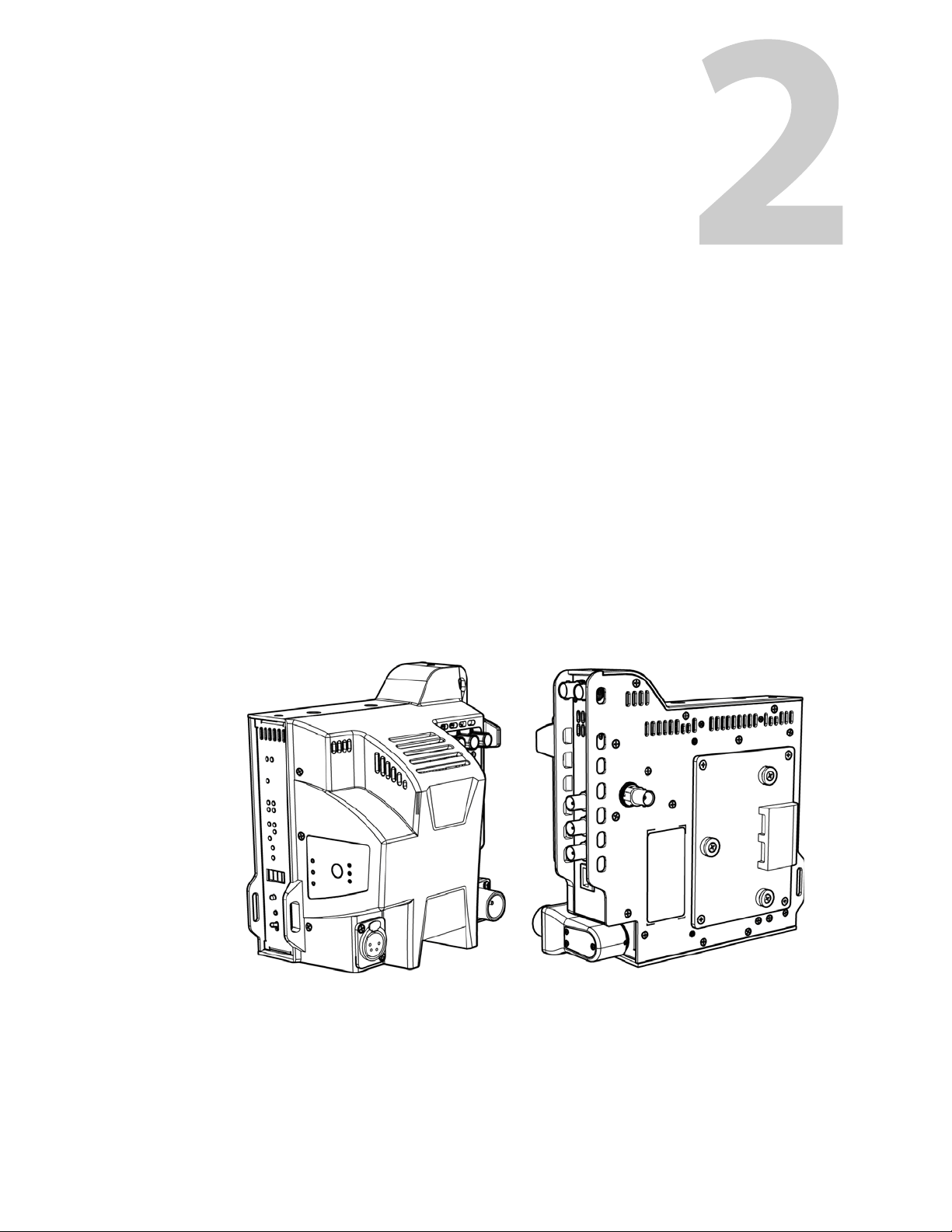
CopperHead 3430AP Camera Unit
The camera unit has controls, connectors and indicators in a variety of locations. The following
diagrams and descriptions will assist you in locating those of interest.
Camera Unit Left Side & Back Side Camera Unit Right Side and Front Side
(attached to the camera)
Fig. 2-1: CopperHead 3430APCamera Unit
The actual appearance of your CopperHead 3430AP Camera Unit will vary depending on the
battery mount option specified at the time of purchase.
3
Page 16
Detailed System Description
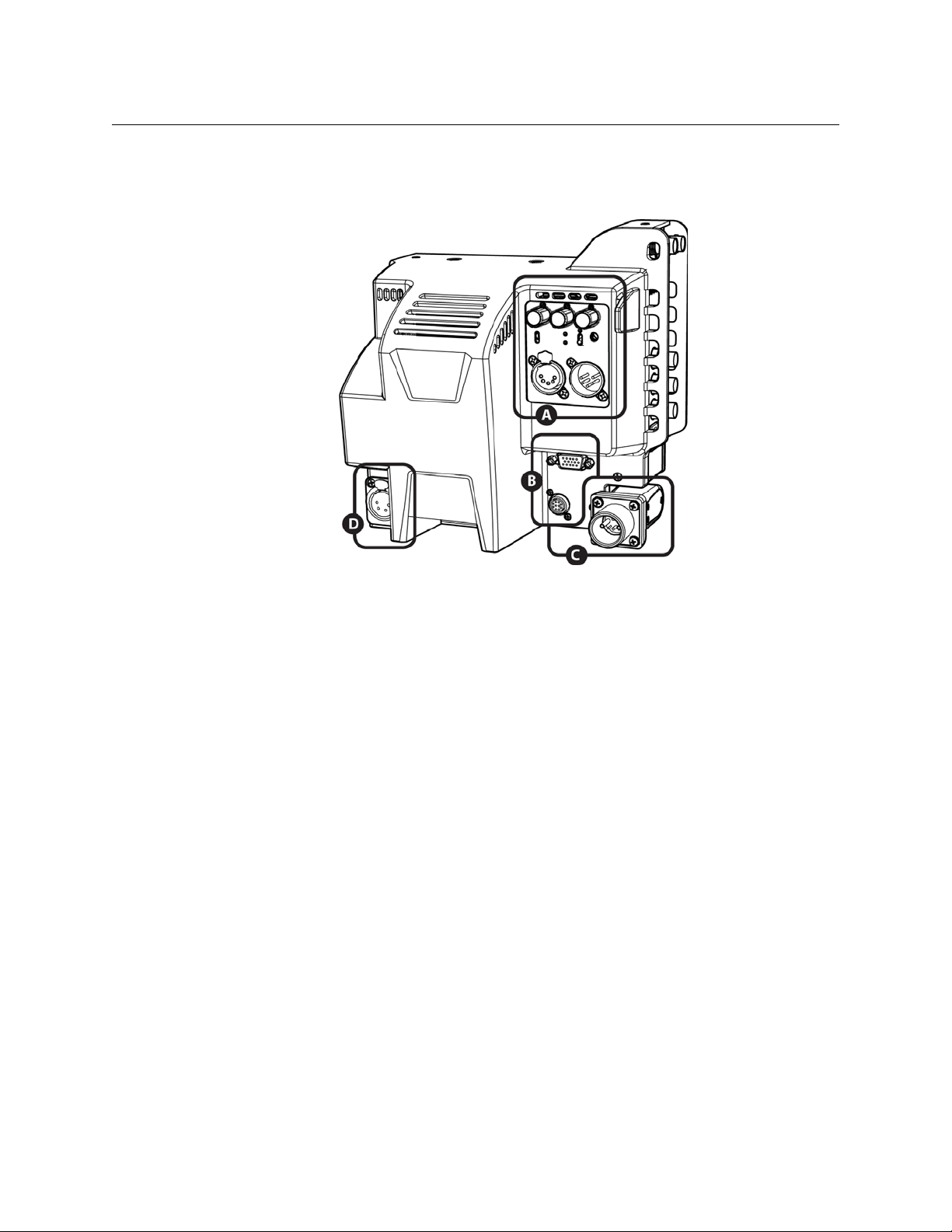
Connectors, Indicators and Controls - Back Side
Fig. 2-2: Back Side Connectors, Indicators and Contreols
There are four areas of interest in this view:
A) Audio/Intercom connector panel & controls
B) Miscellaneous connectors
C) Fiber connector
D) 12 - 17 VDC power output
Each of these areas of interest is described in detail below.
4
Page 17
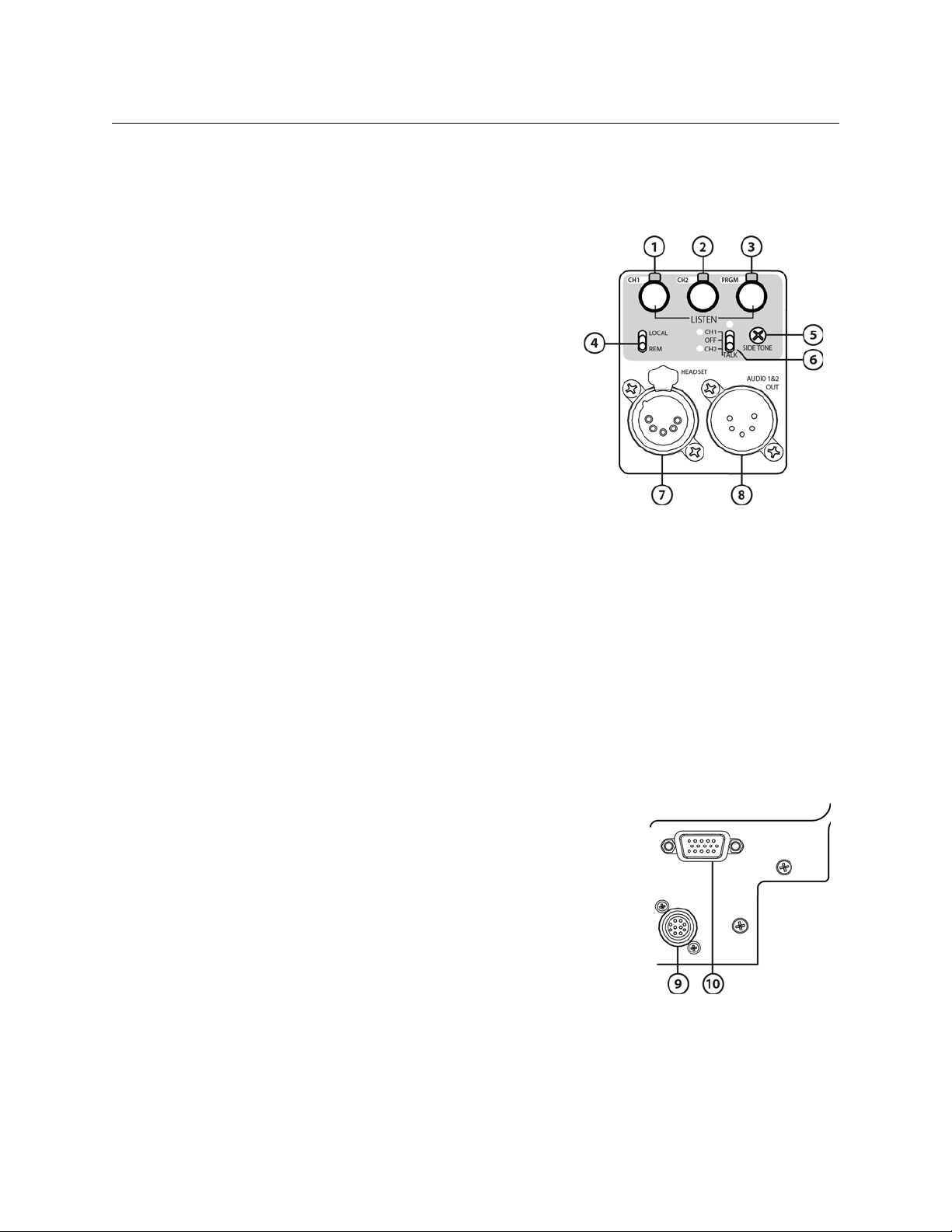
Area A - Audio/Intercom connector panel & controls
1 Intercom 1 Monitor Level Control and activity
indicator
2 Intercom 2 Monitor Level Control and activity
indicator
3 Return Program Monitor Level Control and
activity indicator
4 Intercom Local/Remore switch
5 Side tone control
6 Intercom talkback control
CopperHead 3430AP
User Manual
7 Intercom headset connector
8 Audio 1 & 2 Output Conncetor
For information on Audio/Intercom operation, please see Camera Unit Intercom Operation on
page 43.
Area B - Miscellaneous connectors
For information regarding available cables and customer-furnished cables please see the
Appendices.
9 Camera Remote Connector (for optional Camera
Remote Control unit). This connector also carries a Data
Signal for Serial Communication (RS232/422/485)
(see Appendix A for wiring information)
10 Production DB15HD Connector for Tally, Intercom
Trigger, 2
485)
nd
GPI and Serial Communication (RS232/422/
(see Appendix A for wiring information)
5
Page 18
Detailed System Description
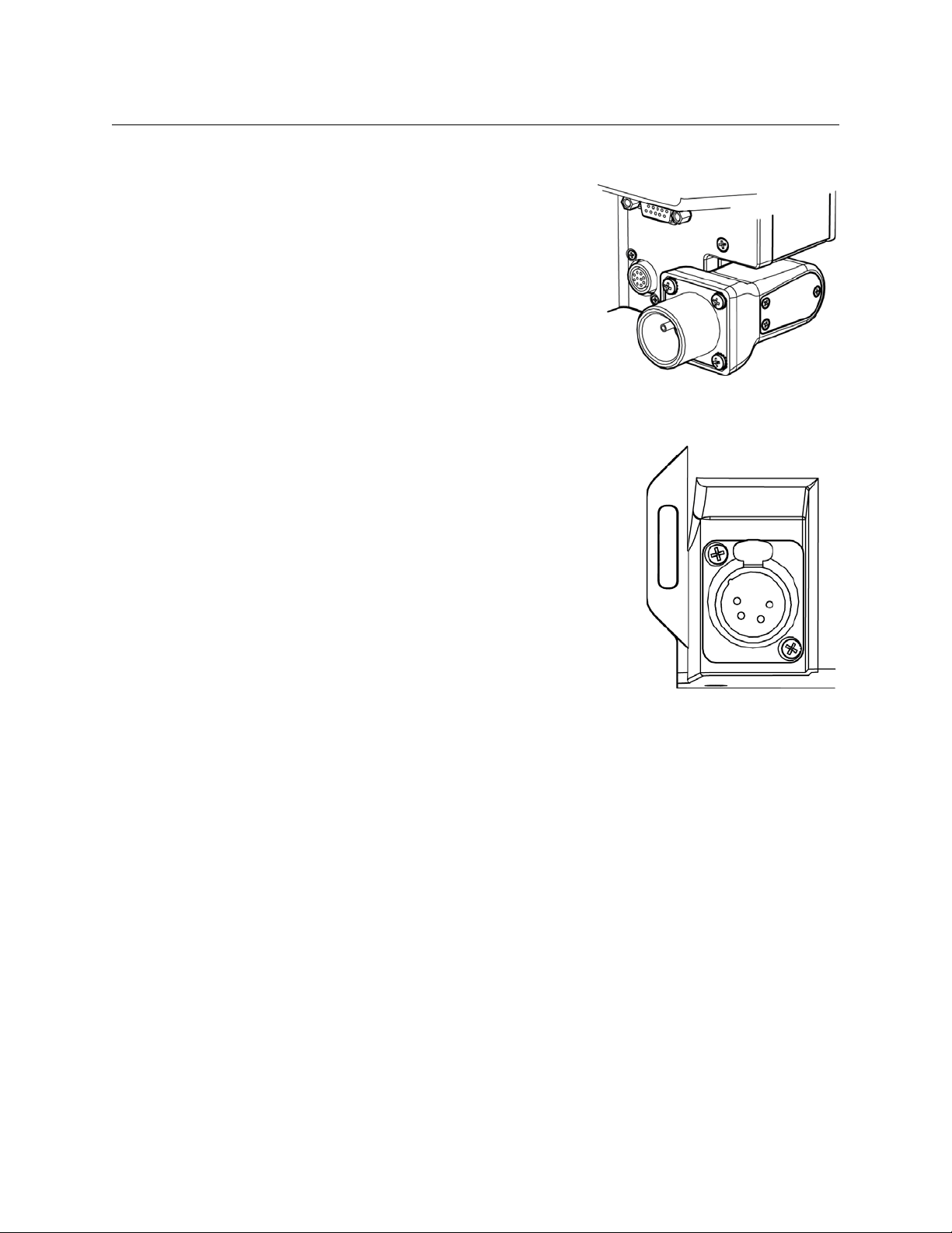
Area C– Fiber Connector
The CopperHead 3430AP Camera Unit is available
only with the SMPTE 304M Hybrid Optical Connector.
Area D - Power Output
The 4-Pin 17 VDC Power Plug can provide up to 30 Watts of
DC power to accessories attached to or near the camera
position.
For information regarding available cables and customerfurnished cables, please see Appendix B.
6
Page 19
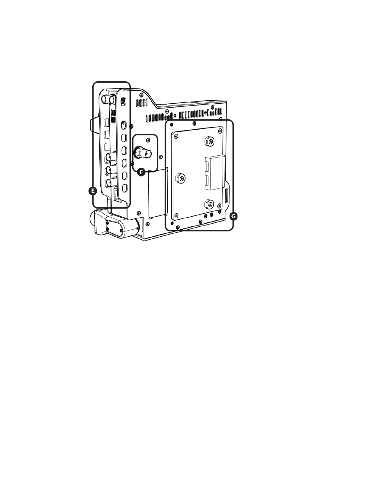
Connectors and Indicators - Front and Right Side
CopperHead 3430AP
User Manual
Fig. 2-3: Front and Right Side Connectors and Indicators
There are three areas of interest on the front and right sides of the CopperHead 3430AP
Camera Unit:
E) Connector panel (right side)
F) Time code output connector (front side).
G) Camera mounting plate (front side)
7
Page 20
Detailed System Description
Area E - Connector panel
11 3D – Dual Link SDI Connectors A & B – Activity
indicators are below each SDI connector (to
Base Station). System can be used as single or
dual link
12 SD-HD/SDI Digital Video Output (from Base Sta-
tion)
13 VBS In (to Base Station). VBS signal paths typi-
cally carry analog video
14 VBS Out (from Base Station)
15 Ethernet (100Mbs)
Area F - Time code output
Time Code Out (from Base Station)
For time code synchronization of multi-camera productions,
and/or video/audio synchronization.
8
Page 21
CopperHead 3430AP
User Manual
Area G - Camera mounting plate
The CopperHead 3430AP is shipped with either the Anton Bauer mount or the Sony V-mount.
Anton Bauer Camera Mounting Plate V-type Camera Momunting Plate
Controls and Indicators - Left Side
Fig. 2-4: Left Side Controls and Indicators
9
Page 22
Detailed System Description
The left side of the camera unit has two areas of interest:
H) Signal/Data indicators
I) Fan Control switch and indicators
Area H - Signal/Data LED activity indicators
The CopperHead 3430AP Camera Unit Indicator Panel has a series of LED
displays that monitor the various signal paths between the Camera Unit and
the Base Station.
For signals remain constant such as time code and video the LED remains
on as a steady green. For signals that fluctuate such as audio, the LED will
reflect the varying signal activity. If the LED is off either the signal has been
lost or it is not in use.
The LED indicators on the left side of the panel indicate signal paths from
the Base Station to the Camera Unit. Right side LEDs indicate signal paths
from the Camera Unit to the Base Station. Note: the 3G/HD/SD-Dual Link
Indicators are located on the opposite (left) side of the Camera Unit adjacent to the 3G/HD/SD-Dual Link SDI Connectors.
The arrow on the panel graphic indicates the direction of the signal - either
to or from the camera unit.
10
Page 23
CopperHead 3430AP
User Manual
16 H D/ SD -SDI Digital Video
Signal
Monitors camera SDI Video to Base Station and SDI
return video to the Camera Unit (this is not the 3DDLink signal)
17 VBS 1 – Analog Video Signal
VBS 1 is used for Return Video from the Camera Unit
to the Base Station and Return Video from the Base
Station to the Camera Unit
Program Audio Channels 1/2
18
Monitors return audio from Base Station to Camera
Unit.
19 Data 1 / CCU
Data 1 - used for a serial control device (RS232, 422,
485)
CCU – used for Camera Control Unit
20 Data 2
Data 2 is typically used for an auxiliary device such as a
robotic pan & tilt head. or a serial control device
(RS232, 422, 485)
21 TC – Time Code
Signal
Monitors Time Code to Camera
22 Ethernet Signal
Monitors Ethernet to Base Station and return from
Camera
23 GPI/Tally 1
Monitors GPI/TRIG Signal or TALLY 1 from camera.
24 Tally 2
Monitors TALLY 2 signal to camera unit.
11
Page 24
Detailed System Description
25 Tally 1 Indicator Light
Indicates the status of the GPI/Tally 1 signal
• Off when the signal is not present
• Bright Red when the signal is present
26 Optical Link Indicator
Indicates the status of the optical connection from base to
camera and camera to base
• Green when both the Base Station and camera control unit
have optical power within normal range.
• Red when either the Base Station or camera control unit
optical power is not within normal range.
27 Rx Optical Display (Digital Status Display)
Four character display in one of five modes. See The CopperHead 3430AP Camera Unit Dig-
ital Display on page 51 for use of this Digital Status Display
28 Base Rx/Dim Push Button
Change four character display mode. Push and release changes display mode. Push and
hold adjusts LED indicator brightness
29 Power Indicator LED
• Green indicates power is applied to the camera control unit.
• Blinking Green indicates a camera control unit error. Refer to DIAG display mode for
details – page 52
30 Power On/Off Switch
Toggle switch controls power to the CopperHead 3430AP Camera Unit, the 12 VDC output
and the camera when using the Sony-V Mount (Camera power control is not available with
the Anton-Bauer mount)
12
Page 25
CopperHead 3430AP
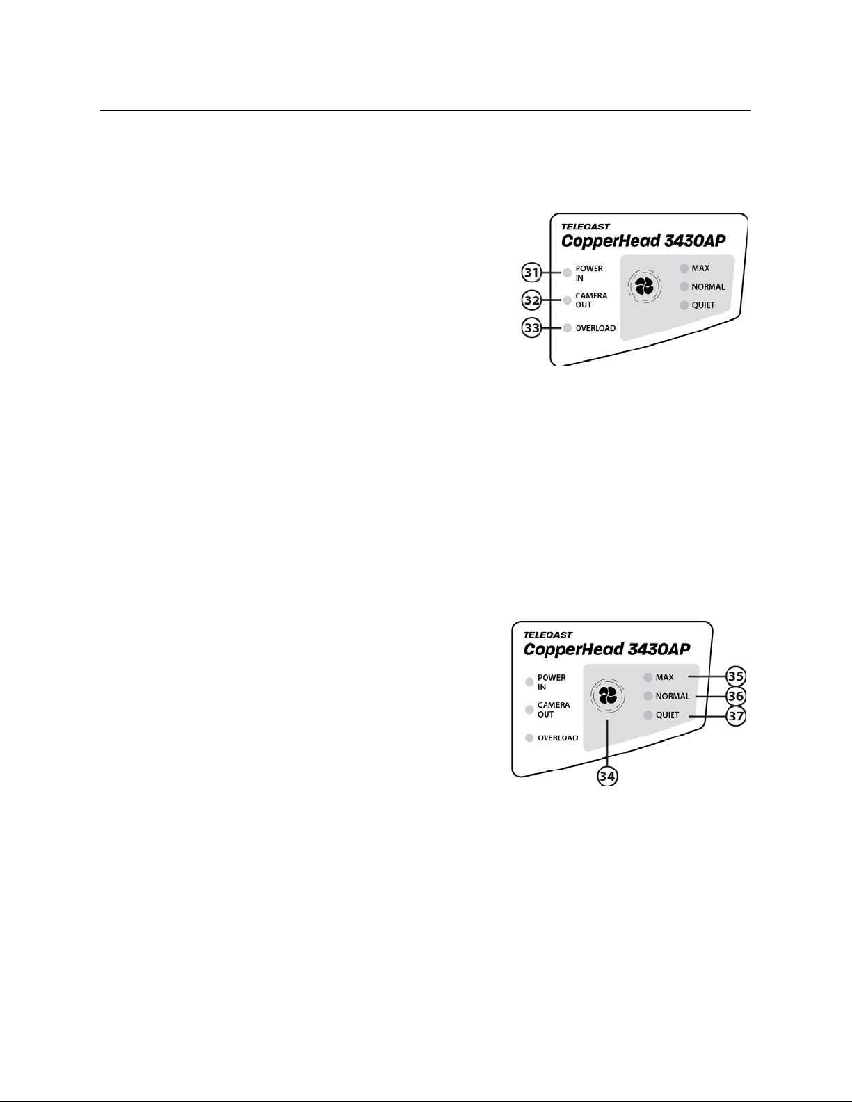
Area I – Power Indicators, and Fan Control Switch and Indicators
Power Indicators
31 POWER IN
• BRIGHT GREEN – CopperHead 3430AP Cam-
era Unit is switched on and the HDX-Plus is
operating at normal voltage
• DIMLY LIT GREEN – CopperHead 3430AP
Camera Unit is switched off and the HDX-Plus
is operating at standby voltage
32 CAMERA OUT
• BRIGHT GREEN – CopperHead 3430AP Cam-
era Unit is switched on and the HDX-Plus is operating at normal voltage. The camera is
receiving normal voltage.
33 OVERLOAD
• BRIGHT RED – Maximum rated power output is reached
• FLASHING RED – Maximum rated power output is exceeded – the CopperHead 3430AP
unit will shut down to protect the system and must be power cycled either at the Camera
Unit or the HDX-Plus to restart the system.
User Manual
Fan Operations
34 Fan Control Switch
Push switch selects between three settings; the
LED corresponding to the selection is illumi
nated:
• MAX – Fan Speed is continuously at maxi-
mum speed
• NORMAL – Fan Speed initially set to lowest
speed and then adjusts based on unit internal temperature – the temperature is never
allowed to be close to the unit maximum
operating temperature.
• QUIET – Similar to NORMAL setting except that the temperature IS allowed to be close to
the unit maximum operating temperature.
35 MAX Indicator
Fan is operating at full speed.
36 NORMAL Indicator
-
Fan is operating in Normal mode and speed increases from minimum speed to full speed
13
Page 26
Detailed System Description
over a temperature range of 55 degrees centigrade to 70 degrees centigrade. Speed
increases more rapidly as unit first begins to increase in temperature.
37 QUIET Indicator
Similar to NORMAL mode except that fan speed increases slowly as unit increases temperature and then more rapidly as the unit approaches maximum allowable temperature.
Fan Diagnostic Mode
The fan switch allows entry into a LED test mode. Push and hold the FAN switch for about five
seconds and the test will begin. At this point all of the LEDs will blink indicating that the fan
system is functioning.
High Temperature Warning
If during regular operation (not the diagnostic mode described above) any of LEDs begin to
blink slowly then the CopperHead unit has reached a temperature of 65 degrees centigrade. If
during regular operation (not the diagnostic mode described above) any of LEDs begin to blink
quickly then the CopperHead unit has reached a temperature of at least 70 degrees centigrade.
If the temperature reaches 70 degrees centigrade confirm that the fan is working correctly in the
unit. If this high temperature is sustained for any period of time damage may occur to the
system. The unit should be turned off and allowed to cool before restarting and the unit should
be checked for malfunction as soon as possible.
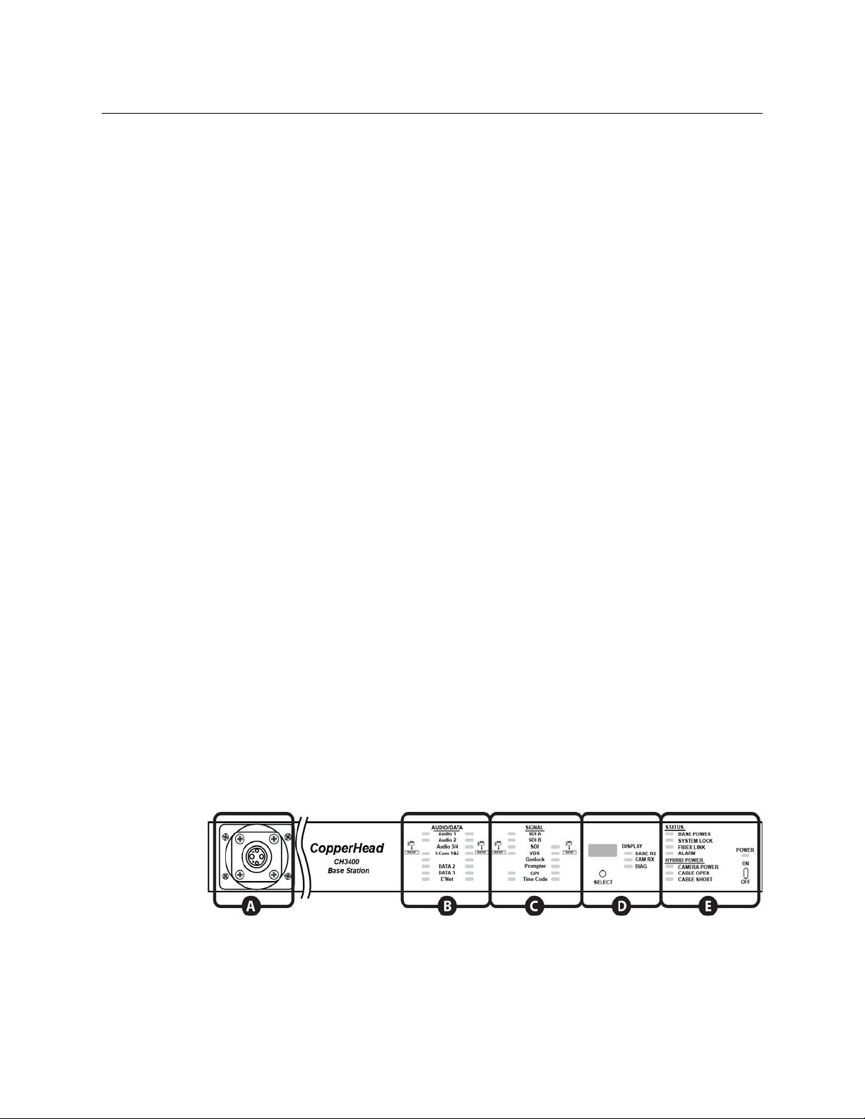
Copperhead 3400 Base Station
The Co pp er h ea d 340 0 Base Station is available with a number of options. The unit is
ordered with a specified Power Module, Audio/Intercom Module and Fiber Connector.
Front Panel
Fig. 2-5: Base Station Front Panel
14
The front panel of the Copperhead 3400 base station has five areas of interest:
Page 27

CopperHead 3430AP
aaaST/UPC
User Manual
A) Optical Connector
See this
Page
B) Audio/Data Indicators
See page 16
C) Video/Data Indicators
See page 16
D) Signal Strength Indicators/Setup
See page 17
E) Status/Power Indicators
See page 17
Area A – Front Panel Optical Connector (Optional)
Area A of the Copperhead 3400 Base Station provides for the optional mounting of the Fiber
Optical Connector on the front of the Base Station instead of the rear of the Base Station. Front
mounting of the optical connectors is normally specified at the time of ordering. Area A is
provided with a blank panel when the normal rear mounting of the fiber connectors is specified.
The Copperhead 3400 Base Station for use with the CopperHead
3430AP Camera Unit is normally delivered with two ST Fiber Optical
connectors for connection to the HDX-Plus power supply.
As noted above existing Copperhead 3400 Base Station units with
other types of connectors can be used with the 3430AP system with
the addition of Fiber Connector jumper cables connecting ST connectors to one of the panel mounted connector types shown below.
Please consult Grass Valleysupport for information regarding the
appropriate jumper cable.
The Copperhead 3400 Base Station may also be equipped with one of these other types of Fiber
Connector. These types of connector are not normally specified for a new CopperHead 3430AP
system.
Neutrik OpticalCOM SMPTE 304M ST/UPC with 5Pin Molex MX
Fig. 2-6: Fiber Connector
Types
15
Page 28

Detailed System Description
Area B – Audio Indicators
LED Indicators to the left side of the label indicate signal paths from the Camera Unit to the
Base Station and right side LEDs indicate signal paths from the Base Station to the Camera Unit.
1 Program Audio Channels
Monitors Return audio from Base Station to Camera
Unit. Channels 3/4 are n/a.
2 I‐Comm (Intercom) Channels 1‐2
Monitors Intercom audio from Camera Unit to
Base Station and from Base Station to Camera Unit
3 DATA 1‐2 Signal
Monitors the serial Data signals to and from Base Station to and from the Camera Unit,
DATA 3 is n/a.
4 E’Net (Ethernet) Signal
Indicates IP Data traffic to and from Camera Unit to and from Base Station
Area C – Video/Data Indicators
5 SDI A‐B
Monitors the 3G/HD/SD-0SDI Dual-Link signals
from the CopperHead 3430AP Camera Unit
6 SDI Digital Video Signal
Monitors SDI return video to the Camera Unit.
7 VBS– Analog Video Signal
Monitors analog Camera video from the Camera Unit to the Base Station and Return video
to the Camera Unit from the Base Station
8 Genlock
N/A for the CopperHead 3430AP system.
9 Prompter
Signals
16
N/A for the CopperHead 3430AP system.
10 GPI
Use the VBS signal path.
Page 29

CopperHead 3430AP
User Manual
Monitors the Tally/GPI signals to and from Base Station and Camera
11 Time
Code
Monitors the house time code from the Base Station to the Camera Unit
Area D – Signal Strength Indicators/Setup
12 Signal Strength Readout in dBm
This display changes between display modes when
selected
13 Readout Function Indicator
BASE RX – Optical Link signal strength received
at Base Station from Camera
CAM RX – Optical Link signal strength received at Camera from Base Station
DIAG – Digital display is in Diagnostic mode
14 Select
Button
Unit
Unit
Chooses between three modes of operation
For details on how the setup/diagnostic functions operate, please see The CopperHead
3400 Base Station Digital Display on page 47.
Area E – Status/Power Indicators
15 Power Switch & Power Indicator
Toggle switch to enable or disable Base Station
power.
LED turns Green when on/off switch is changed to
the ON position.
For an AC-powered base station to be properly powered, the AC Mains switch on the rear
of Base Station must be in the ON position.
16 Hybrid Power Indicators
The Hybrid Power indicators are N/A in the CopperHead 3430AP system
17
Page 30

Detailed System Description
17 Status
Indicators
BASE POWER - indicates the status of all power
levels in the Base
Station
• Green when all power levels are normal.
• Red when any power level is not normal.
SYSTEM LOCK - indicates that the Base
Station is communicating with the Camera Unit.
• Green when communicating with Camera Unit
• Red when it is not communicating with the Camera Unit
Note: Hybrid Power Indicators are present only on an AC-powered base station.
FIBER LINK - indicates the optical power status of the Base
Station and camera
• Green when both the Base Station and camera optical power are within a normal
range.
• Orange when either the Base Station or camera optical power is not within a normal
range
• Red when both the Base Station and camera optical power are not within a normal
range
ALARM - indicates that some error condition exists in either the Base Station or the camera.
• Red if there is a Base Station error. Refer to the Base Station DIAG for details on the
error.
• Orange if there is a camera error. Refer to CAM DIAG for details for the error.
18
Rear Panel
Fig. 2-7: Base Station Rear
The rear panel of the Copperhead 3400 base station has four areas of interest:
A) Power & Fiber Connectors
See page 19.
B) Sync/Data/Control Connectors
See page 20.
Panel
Page 31

CopperHead 3430AP
User Manual
C) Video/Ethernet Connectors
See page 20.
D) Audio/Intercom Connectors
See page 20.
Area A – Power & Fiber Connectors (Power Module)
The Copperhead 3400 Base Station for the CopperHead 3430AP system can be configured with
Internal AC Power or external 12 Volt power. Multi-pin connector wiring suggestions are
covered in the Appendix.
Power
Internal Power
18 AC Power Receptacle and 4AMP Dual Fuse
19 For Future Use3
20 AC Mains Switch
21 ST Connectors & Molex power connector
External Power
22 12V DC External Power Supply input connector
23 12V DC Input – terminal block
Options:
Assembly
100-240V 50/60 Hz
See Page nnn for the Fuse Specification
(XLR 4
Pin)
19
Page 32

Detailed System Description
Area B – Sync/Data/Control Connectors
24 Sync/Black Burst input connector & Loop through
25 Video Prompter input to Camera (N/A for 3430AP)
26 Camera Remote Control Panel Connector
27 Data/GPI Multi‐Pin Connector
28 Time Code In to Camera
29 Time Code Out from Camera (N/A for 3430AP)
Area C - Video/Ethernet Connectors
30 Ethernet connector – 10BaseT/100BaseT
31 VBS Output from Camera
32 VBS Return Video source Input to Camera
33 SDI Program from Camera Unit outputs 1‐2
(N/A for 3430AP)
34 SDI Return Video source Input to Camera
35 3D/HD/SD-SDI Dual‐Link from camera outputs A‐B
Area D – Audio/Intercom Connectors
The Copperhead 3400 Base Station can be configured with one of three different Intercom
options. The connection and practical use of each of these options is covered in Intercom
Usage beginning on page 42. Multi-pin connector wiring is covered in Appendix A.
Four Wire Intercom Module
36 Audio In Multi‐pin connector
37 Audio Out Multi‐pin connector
20
38 Ch‐1 Intercom connector
39 Ch‐2 Intercom connector
Page 33

RTS TW Intercom Module
CopperHead 3430AP
User Manual
40 Intercom
41 Intercom Loop Through
Clear‐Com Intercom Module
42 Ch‐A Intercom Connector
43 Ch‐B intercom Connector
Input
HDX-Plus Power Unit
The HDX-Plus Power Supply Unit is the required standard power supply for the CopperHead
3430AP Transceiver System. The HDX-Plus will supply up to 200 watts at 17 VDC to the CopperHead 3430AP Camera Unit.
Fig. 2-8: HDX-Plus Front Panel
The HDX-Plus has three areas of interest:
A) AC Power module - see page 22
B) Fiber optic connectors - see page 22
C) System indicators - see page 22
21
Page 34

Detailed System Description
Area A - AC Power Module
The HDX-Power Plus can utilize 100-240 VAC (50/60kHz) power. The
system will auto-detect the incoming voltage level
The power switch controls power on/off for the entire CopperHead
3430AP system.
Area B - Fiber Connectors
The HDX-Plus power supply connects to the
Copperhead 3400 base station with a pair of ST
Fiber connectors using Tactical Fiber Optic cable.
The HDX-Plus power supply connects to the
CopperHead 3430AP Camera Unit using SMPTE
304M Hybrid connectors over Hybrid Fiber Optic
cable.
Area C - System Indicators
The HDX-Plus power supply provides two types of
indicators:
• The first group is power and cable integrity
indicators.
• The second group is an Optical Power meter.
Power/Cable Integrity Indicators
This area provides the following LED indicators:
HIGH VOLTAGE
• Yellow when system High Voltage is present
OVER TEMP
• Orange if the HDX-Plus cooling fan fails
• Red if the HDX-Plus senses internal high temperature
• Flashing Red if the HDX-Plus has shut down because of
high temperature
22
Page 35

CopperHead 3430AP
User Manual
AC ON/OVERLOAD
• Green when system normal operations or when the HDX-Plus has AC Power
• Red when the HDX-Plus power supply is overloaded
• Off when switch is off, no AC power or fuse is blown
CABLE FAULT
• Red if a high voltage short or open condition is detected
CAMERA PSU
• Green if the Camera Unit power supply is detected
• Red if the 3430 Camera Unit power supply is shut down due to an overload.
Optical Power Monitoring
The HDX-Plus power supply provides Optical Power monitoring for both the Camera unit and
the Base unit. The metering uses Multi-Colored LEDs with indicators covering a range of -21dBm
to 0 dBm. The CopperHead 3430AP Transceiver system is specified to operate at Optical Power
levels above -22dBm.
The unit has two rows of LEDs:
• Top row indicates the optical power level at
the camera unit
• Bottom row indicate optical power level at
the base station
All of the indicator LEDs are multi-color:
• Green - good power
• Yellow Orange - Marginal power
• Red - Insufficient power.
Note: The CopperHead 3430AP system is, of course, a digital system and therefore the link will
operate properly at the lowest acceptable signal strength. If the signal strength dips
below the minimum acceptable level the link will not operate.
23
Page 36

Detailed System Description
Power Monitoring Scenarios
The following diagrams illustrate operational scenarios in which the Optical Power Indicator
LEDs provide a visual indication of the CopperHead 3430AP fiber optical status.
Thisscenarioisagoodoperationalsituation.The‐
6dBmreflectstypicalsignalstrengthacrossaFiber
Opticcablerun.TheCopperHead3430APsystem
willrunperfectlyatthissignalstrength.
ThisscenarioshowsabadFiberOpticlinkandno
OpticalPowerineitherdirection.Checktoseeif
there
isaproblemwiththeFiberOpticconnection
orcable.
ThisscenarioshowsjustenoughOpticalPower
presenttoprovideanoperationallink.Checkthe
FiberOpticcablerunforpossibledamageorphys‐
icalinterferencesuchassharpbendsinthecable.
AlsochecktheFiberOpticconnectorsfordust,
dirt
ordamage.
ThisscenarioshowslowOpticalPowerbutmore
thanadequateforausablelink.Keepaneyeon
thereadingtomakesureitisconsistent.Check
thecablerunasaboveandchecktheFiberOptic
connectorsfordust,dirtordamage.
24
Page 37

HDX-Plus Power Output and Derating Chart
CopperHead 3430AP
User Manual
25
Page 38

Detailed System Description
26
Page 39

Overview
Installation and Connection
Chapter 3 describes the installation and connection of the CopperHead 3430AP system,
including the Camera Unit and the base station.
Topics
Overview . . . . . . . . . . . . . . . . . . . . . . . . . . . . . . . . . . . . . . . . . . . . . . . . . . . . . . . . . . . . . . . . . . . . . . . . . . . page 27
Mounting the CopperHead 3430AP Camera Unit to the Camera . . . . . . . . . . . . . . . . . . . . . page 27
Connecting the CopperHead 3430AP Transceiver System . . . . . . . . . . . . . . . . . . . . . . . . . . . . page 28
Connections to the CopperHead 3400 Base Station . . . . . . . . . . . . . . . . . . . . . . . . . . . . . . . . . . page 30
Connections to the CopperHead 3430AP Camera Unit . . . . . . . . . . . . . . . . . . . . . . . . . . . . . . . page 33
This chapter describes the physical installation of the CopperHead 3430AP Transceiver System.
The following areas are covered:
• Mounting of the CopperHead 3430AP Camera Unit to the camera
• Connecting the three components of the system – The Camera and Camera Unit, the HDX-
Plus Power Supply and the CopperHead 3400 Base Station
• Detailed information for all system connections
Mounting the CopperHead 3430AP Camera Unit to the Camera
This example illustrates the mounting of an Anton Bauer battery system. Your system may
differ.
Fig. 3-1: Mounting the CopperHead 3430AP Camera Unit to the Camera
27
Page 40

Installation and Connection
1 Position your camera so that you can easily access the battery mounting plate at the rear of
the camera. Ensure that the camera is well supported and stable.
2 Attach the CopperHead 3430AP Camera Unit to the camera battery mounting plate. The
mounting is mechanically identical to attaching a battery. See Camera Unit Connections
on page 35 for details of the camera unit-to-camera connections..
For configuration please see Chapter 4.
Connecting the CopperHead 3430AP Transceiver System
Prior to connecting your CopperHead 3430AP Transceiver System please ensure that each of the
required cables is available for use. This includes standard video, audio and data cables as well as
any custom multi‐pin cable sets required for your particular installation. Please see Appendix A
for information regarding cables, signals and custom multi‐pin cable fabrication.
Note that the use of any existing CopperHead 3400 Base Station without ST Fiber Connectors is
not covered in this user guide.
Covered in this chapter are:
1 Overview of connections between the three main system components.
2 Connections between the CopperHead 3400 Base Station and the base video infrastructure &
power components
3 Connections between the CopperHead 3430AP Camera Unit and the video camera & power
components.
Note: The following fiber connection scenario does not take into account any customized cable
and connector installations you may have at your facility. For assistance regarding more
complex connection situations please contact Grass Valley or your local authorized dealer.
28
Page 41

CopperHead 3430AP
User Manual
Connection Overview of the CopperHead 3430AP Transceiver
System
Fig. 3-2: Connection Overview of the CopperHead 3430AP Transceiver System
Between the Base Station (1) and the HDX-Plus Power Supply (4) connect a pair of ST Fiber
Cables (5).
Power the HDX-Plus Power Supply locally by connecting to AC Power. Between the HDX-Plus (4)
and the Camera Unit connect a length of SMPTE Hybrid Fiber Cable (6). Each end of the fiber
cable will have an SMPTE 304M Connector (3).
The Base Station connector (1) may be mounted either on the front or back of the Base Station.
The camera will be powered by the CopperHead 3430AP Camera Unit (2).
The Base Station will be powered by connection to local AC power either directly to the AC
Mains or by use of a 12 VDC external power supply depending on the model of CopperHead
3400 Base Station in use (7).
29
Page 42

Installation and Connection
Connections to the CopperHead 3400 Base Station
Fig. 3-3: CopperHead 3430AP Base Unit Connec
tions
Multi‐Pin Cable Assemblies Used with the CopperHead 3400 Base Station
A Camera Remote Control (Remote) Connector–
Connect either your Camera Remote Control or the Grass Valley Universal
CHRCP-2050A or CHRCP-2050-LCD.
See Appendix B for a list of Grass Valley-supplied cables
B Data/GPI Connector
Connect a Remote Pan/Tilt/Zoom Control Unit and connect to one GPI Out and two GPI
inputs. Usage of GPI/Os other than Tally and Intercom control is outside of the scope of this
User Guide.
Serial Control devices using RS232/422/485 can be controlled over this signal path. See
page 61 for wiring details
CAudio In Connector
Connect Intercom Program Audio and four Production Audio Channel outputs.
See page 61 for wiring details
Controller –
30
Connectors into and out of the CopperHead 3400 Base
This information duplicates some of that from above sections. It is presented here to provide a
single list of all Base Station connections. . Connectors that are present on the CopperHead 3400
Station
Page 43

CopperHead 3430AP
User Manual
Base Station but not used in the camera configuration are noted as Not Available (NA). Key
numbers refer to the diagram above.
1 & 21
Power In
Connect a standard 3 conductor AC Cable (IEC
Plug) 100-240V 50/60 Hz
standard or a 12V
DC ADAP power source (4 Pin)
4 Fiber Connector
(This connector can be mounted on the Base Station Front Panel – see page 15)
Connect the ST fiber connectors from the HDX-Plus power saupply.
5Sync In/Loop
BNC Connector – standard Genlock/Sync/Tri-Level sync signal. The loop-through is self-terminating.
6Prompter In
N/A in 3430AP configuration
7Time Code In
BNC Connector – Standard time code signal sent to camera – typically originating from a
“
house” time
primary camera may be used
base station via connector 8 and then be
ated Copperhead Base Stations
8Time Code Out
code generator feed available at the Base Station. On remote productions the
to originate the system time code feed (signal would return to
distributed to other cameras through the associ-
N/A in 3430AP configuration.
9Multi‐Pin Connector A
DB9 – 9 pin serial connector connected to an optional Camera Remote Control Panel
Power to the Base Unit (and the Camera Unit & Camera) must be turned
off when connecting the Camera Remote Control Panel – connecting with
th
e power on can seriously damage your equipment.
10 Multi‐Pin Connector B
DB15 – 15 pin serial connector connected to a breakout of Tally and GPI signal connectors.
T
ypically this connector will be connected to the Camera Tally system originating at the
Production Switcher or
ment. Additional custom GPI contact closures can be configured.
See page 66 for a typical configuration.
11 Ethernet Connector – 10Bt/100Bt capable
Designed to carry IP traffic data between the
PC or other
device such as a Wireless Access Point can be connected to the Production Envi-
the Tally Management system used in your production environ-
Base Station and the Camera Unit. A laptop
31
Page 44

Installation and Connection
ronment IP network.
12 VBS Out
BNC Connector -Typically used for SD Monitoring Video return from the Camera
13 VBS In
BNC Connector – Typically used to send SD return video to the camera – an example is
monitor out from the production switcher. Also used for Prompter feed.
14 SDI Out 1 & 2 (this carries the HD feed (not the 3D/Dual Link) from the camera)
N/A in 3430AP configuration.
15 SDI In
BNC Connector – Typically used to send HD return video to the camera – an example is program out
SDI Out A & B (this carries the dual 3D/Dual Link signals from the camera)
16
BNC Connectors
from the Production Switcher
17 Audio In ‐ Multi‐Pin Connector
DB25 – 25 pin Connector follows the Tascam TDIF standard. The CopperHead 3430AP
Transcei ver
handles return audio
Page 93 for sample wiring.
18 Audio Out ‐ Multi‐Pin Connector
DB25 – 25 pin Connector follows the Tascam TDIF standard. The CopperHead 3430AP
Transcei ver
nector handles return
19 & 20 Intercom Connectors #1 & #2
XLR 3 pin or 5 pin Connector depending on configuration. One of three options will be
installed
each
22 12V Termiinal Block
Terminal Block – bare wire connector. This can be used in place of the ADAP power connection in installations that have 12V power distributed as part of their infrastructure. Do not
use this at the same time as the ADAP power connection.
23 12V Terminal Block
System accommodates up to two Audio Channels at Line Level. This connector
to the Camera location as well as intercom Program Audio. Please see
System accommodates up to two Audio Channels at Line Level. This con
audio to the Camera location. Please see Page 94 for sample wiring.
(4-wire intercom, RTS or Clear-Com). Please see Chapter 6 for information on using
of the Intercom Options
.
-
32
Terminal Block – bare wire connector. This can be used in place of the ADAP power connection in
not use this at the same
installations that have 12V power distributed as part of their infrastructure. Do
time as the ADAP power connection (21).
Page 45

CopperHead 3430AP
Connections to the CopperHead 3430AP Camera Unit
User Manual
Fig. 3-4: CopperHead 3430AP Camera Unit Back Side Connections
This information duplicates some of that from above sections. It is presented here to provide a
single list of all Camera Unit connections. Key numbers refer to the diagram above.
Multi‐Pin Cable Assemblies Used with the CopperHead 3430AP Camera Unit
A) Camera Remote Control (Remote) Connector
Connect this to the CCU input on your camera. The Grass Valley-supplied cable has a red
sleeve at the end to be connected to the CopperHead 3430AP Camera Unit.
See Appendix B for a list of Grass Valley supplied cables.
B) Data/GPI /Tally Connector
This connector carries a number of control, GPI and Tally signals.
See page 63 for wiring details
33
Page 46

Installation and Connection
Connectors into and out of the CopperHead 3430AP Camera Unit Back Side
1 3G/HD/SD Dual Link Inputs
BNC Connectors – Carries 3D/Dual Link camera video from the Camera(s) to the Camera
Unit. This requires BNC jumper cables between the Camera Unit and the Camera (s).
2 HD/SD - SDI Output
BNC Connector – Carries return video from the Base Station to the Camera Unit. Typically
this will feed a camera viewfinder or an HD viewing monitor at the camera location.
3 VBS In
BNC Connector – Carries SD Analog video from the Camera to the Camera Unit. This requires
a short BNC jumper cable between the Camera Unit and the Camera. Can be used to pro
vide technical monitoring from camera as with superimposed camera menus and other
information.
4 VBS Out
BNC Connector – Carries SD Analog video from the Base Station the Camera Unit. Typically
this will feed an analog viewing monitor or prompter at the camera location.
5 Ethernet Out
-
RJ45 Connector – Carries IP Data. Typically connects to a Laptop computer or perhaps a
wireless access point at the camera location. Any IP traffic controlled equipment can be han
dled through this signal path.
6 Fiber Connector
Swivel Mounted SMPTE 304M Fiber Optic Cable receptacle.
7 Time Code Out
BNC Connector – Carries Time Code signal from the Camera Unit to the Camera. This is master time code from the Base Station. This requires a short BNC jumper cable between the
Camera Unit and the Camera.
8 Aux Power Output
XLR 4 Pin Female Connector – Provides 17 VDC power to accessories on or near the camera.
Insure that the total power consumption of 30 watts is not exceeded.
9 Audio 1 & 2 Out
XLR 5 Pin Male Connector – Provides Return Audio Out from camera for Channels 1 & 2. Typically connected to a local monitor at the camera position.
10 Intercom Headset Out
XLR 5 Pin Female Connector – Provides two channels of two-way intercom and the Intercom
Program audio feed
11 Data Connector
-
34
Multi-Pin Connector B – DB15 15 Pin Serial Connector. This carries serial control signals for
lens and remote pan & tilt units as well as GPI, Intercom Trigger (GPI) and Tally signals.
Miranda Technologies Inc. supplies a number of pre-configured breakout cables for use
Page 47

CopperHead 3430AP
User Manual
with this connector. See Appendix B for details of available cables.
12 Camera Remote Connector
Multi-Pin Connector A– 10 Pin Hirose Connector. This is normally a Grass Valley supplied
ca
ble. It connects the Camera Unit to the Camera CCU in to allow operation of the Camera
Remote Control Panel. See Appendix B for details of available cables.
Power to the Camera Unit & Camera must be turned off when connecting the
Camera Remote Control Panel Cable– connecting with the power on can seriously damage your equipment.
Camera Unit Connections
The following diagrams show example connections between the CopperHead 3430AP Camera
Unit and the Camera. Your setup may not require all connections shown.
Camera Unit (Side and Front Panel Connectors) to Camera Connections
Fig. 3-5: CameraUnittoCameraConnections(SideandFrontPanelConnectors)
35
Page 48

Installation and Connection
Camera Unit (Rear Panel Connectors) to Camera Connections
Fig. 3-6: Camera Unit to Camera Connections (Rear Panel Connectors)
36
Page 49

Operation
Chapter 4 describes the set-up and operation of the CopperHead 3430AP transceiver system.
Topics
Operation of the CopperHead 3430AP Transceiver System . . . . . . . . . . . . . . . . . . . . . . . . . . . page 37
Set Up of the CopperHead 3430AP Transceiver System for Operation . . . . . . . . . . . . . . . . page 38
Connecting and Managing the Fiber Cable . . . . . . . . . . . . . . . . . . . . . . . . . . . . . . . . . . . . . . . . . . page 38
Powering the System . . . . . . . . . . . . . . . . . . . . . . . . . . . . . . . . . . . . . . . . . . . . . . . . . . . . . . . . . . . . . . . page 40
Intercom Usage . . . . . . . . . . . . . . . . . . . . . . . . . . . . . . . . . . . . . . . . . . . . . . . . . . . . . . . . . . . . . . . . . . . . page 42
Using the Digital Displays . . . . . . . . . . . . . . . . . . . . . . . . . . . . . . . . . . . . . . . . . . . . . . . . . . . . . . . . . . page 46
The CopperHead 3400 Base Station Digital Display . . . . . . . . . . . . . . . . . . . . . . . . . . . . . . . . . . page 47
The CopperHead 3430AP Camera Unit Digital Display . . . . . . . . . . . . . . . . . . . . . . . . . . . . . . . page 51
Standard Operation . . . . . . . . . . . . . . . . . . . . . . . . . . . . . . . . . . . . . . . . . . . . . . . . . . . . . . . . . . . . . . . . page 53
Shutting Down the System . . . . . . . . . . . . . . . . . . . . . . . . . . . . . . . . . . . . . . . . . . . . . . . . . . . . . . . . . . page 53
Troubleshooting . . . . . . . . . . . . . . . . . . . . . . . . . . . . . . . . . . . . . . . . . . . . . . . . . . . . . . . . . . . . . . . . . . . . page 54
Operation of the CopperHead 3430AP Transceiver System
This chapter describes in detail the operation of CopperHead 3430AP Transceiver System.
Please keep in mind that a wide variety of options and variations are available in using this
product and so not every possible operational environment can be described.
The following topics are covered:
1 Set up of the CopperHead 3430AP Transceiver System
2 Connecting and Managing the Fiber Cable
3 Connecting the Fiber Cable
4 Powering the System
5 Understanding Intercom usage with the CopperHead 3430AP
6 Using the Digital Displays
7 Standard Operation
8 Shutting Down the System
9 Troubleshooting
37
Page 50

Operation
Operation of the CopperHead 3430AP Transceiver System
Set Up of the CopperHead 3430AP Transceiver System for Operation
This section provides an overview of setup of the CopperHead 3430AP Transceiver System for
operation. The following sections provide additional detail on each aspect of setup and
operation.
It is important that you do an initial setup and test of your CopperHead 3430AP Transceiver
System as soon as your receive it, in order to confirm proper operation and to provide training to
you and your team
Use the following list of items as an overall checklist for setup.
1 It is highly recommended that you do not attempt to power up the system until all con-
nections are made and in particular the Fiber Optic Cable has been connected at both
ends. If you need to power up either the CopperHead 3400 Base Station or the CopperHead 3430AP Camera Unit, make sure that the Fiber Connectors are securely capped. This
will protect them from damage or dirt and protect you from eye damage.
Make sure to connect the Camera Remote Control cable to the Base Station and Remote
Control Panel when the Base Station power is turned off.
2 When setting up the CopperHead 3430AP Camera Unit and associated Camera you will
need to do the following:
a. Make sure all cables running between the CopperHead 3400 base station and the HDX-
Plus power supply and local AC power cords are properly managed and secured..
b. Mount the camera and CopperHead 3430AP Camera Unit as shown on Page nnn
c. Connect all required cables according to Chapter 3. The order in which you connect
the cables makes no difference. BUT...
d. Turn OFF the camera power before connecting the camera remote control cable to the
camera unit and camera.
e. Set up the intercom talk back switches and level controls as desired. Please see Inter-
com Usage on page 42 for details on Intercom operation with the CopperHead 3430AP
Camera Unit.
3 Deploy the Fiber Cable (see the next section) – you are now ready to power up the system.
prior to
an actual production.
Connecting and Managing the Fiber Cable
Connecting and managing the Fiber Cable between the CopperHead 3430AP Camera Unit and
CopperHead 3400 base station or an intermediate power supply requires you to perform four
tasks:
1 Plan the route the Fiber Cable will take between the Camera Unit and HDX-Plus power sup-
ply, and the Base Station and power supply
2 Run the Fiber Cable along the planned route
3 Connect the Fiber Cable Connectors at each end
38
Page 51

CopperHead 3430AP
User Manual
4 Power up the HDX-plus power supply, the Camera Unit and the Base Station, and check the
Fiber Optic Cable Link and signal strength
Planning the Fiber Cable
Obviously the longer the planned cable run the more planning required. It also makes a difference whether you are running Tactical Fiber Cable or Hybrid Fiber Cable as these affect both the
length and the type of exposure the cable can endure.
When planning your cable route take into the consideration the following:
1 Possible obstacles that might cause you to run short of cable – you may need to take a
more indirect, but achievable route
2 Possible hazards to the cable – while tactical fiber is extremely durable it is not immune to
damage. An obvious hazard is running the cable across a lawn scheduled to be cut during
your live production. Make sure the empty roadway at 6AM will not be filled with heavy
equipment when it comes time to retrieve your cable
3 Possible interference (physical) with the cable that might cause it to bend or kink to an
extent that unacceptable signal loss occurs.
4 Safety hazards – make sure that the cable will not cause a tripping or tangling hazard
with people, animals or vehicles.
5 Decide whether the Fiber Cable is to be unspooled from the Base Station location or the
Camera location. Typically the reel is kept close to the base station. However if there is a
chance the Camera location may need to move further away from the Base Station after initial placement it makes sense to place the reel at the camera end. Make sure there is
enough free cable coming out of the stationary end of the cable reel to accommodate a
well‐managed connection to the camera.
Route
Planning the cable route requires common sense and the ability to foresee the unforeseen.
Running the Fiber
Do the following when running your Fiber Cable:
1 Make sure that both ends of the Fiber Cable are securely capped. In this case the concern is
dirt and damage. ANY dirt in the connector can adversely affect Fiber Optical performance
and potentially cause you to lose the use of your camera while the problem is diagnosed
and remedied.
2 If the cable run is long or if you will lose sight of the spooling out cable reel make sure you
have appropriate assistance in running out the cable. When retrieving the cable, assistance to prevent the cable end from being caught or tangled up could be critical. Don’t
start reeling in the cable on your own and assume the Connector end will make it back to
home base safely.
3 When unspooling the cable ALWAYS make sure the stationary end (the end that goes to
the Base Station or Power Supply) us securely contained within the reel. A loose Connector
can bang around and be damaged and NEVER connect the stationary end of the Fiber
Cable
39
Page 52

Operation
Operation of the CopperHead 3430AP Transceiver System
Cable to the Base Station or Power Supply and the start unspooling the Fiber Cable. Severe
damage to the cable could occur due to extreme spiraling of the connected portion of the
cable.
4 Prior to connecting the Fiber Connectors to the Base Station and Camera Unit inspect both
connectors. If required, clean with dry compressed air or with technical wipes that have
been moistened with isopropyl alcohol. Fingerprints or other dirt on the optical connector
end surfaces will reduce the optical signal level on the fiber. If the connectors have been
properly capped during storage and movement you will not likely have a problem.
However if a connector has been dropped or dragged through dirt or exposed to dust
cleaning is recommended.
5 Once the Fiber Cable has been connected it is time to secure the Fiber Cable run. Make
sure there are no cable hazards in the run. Secure the cable with cable guards and/or gaffers
tape to insure safety.
6 Now the system can be powered on. Plugging in Fiber Cable connectors with the power
on will not damage the system but is not recommended because of the chance of possible
eye damage.
7 When re‐spooling the Fiber Cable on to the spool, guide it across the entire width of the
spool so that it winds evenly and the possibility of cinching or kinks is greatly reduced.
Powering the System
The CopperHead 3400 Base Station and the CopperHead 3430AP Camera Unit each have
a power up routine which tests the equipment and performs a system diagnostic.
40
Page 53

CopperHead 3430AP
User Manual
Powering the CopperHead 3400 Base Station
Base Station Main Power 1 Turn on the Base Station Power Mains Switch located at the
rear left (when
overall diagram. This switch is only on Base Station units with
internal power. The front panel power light will come on and be
red until the next step.
facing the back of the Base Station) #3 on the
Base Station Power
Four Character Display
LED Indicator
progression
REV display
Scrolling
PAU S E
Diagnostics
Current Status Displayed
Turn on the Front Panel Power Switch located at the front
2
right. #15 on the
turns from red to green.
The 4 character display indicates TEST and all front panel
3
LEDs turn red, then green, then orange, then off.
The LED color test is followed by REV and the revision of
4
the display
The REV indication is followed by “miranda.com” scrolling
5
across
the 4 character display. If there's no scrolling, please
contact Grass Valley - A Belden Brand support for assistance.
The scroll is followed by about a 3 second interval used to
6
synchronize all
The front panel will cycle through the diagnostics displays –
7
See Section 6.5
After the 3 second pause, all the front panel displays update
8
with current
the camera- related status lights will show red.
overall diagram. The power monitor indicator
microcontroller firmware.
the microcontrollers in the base station
status. If the Camera Unit is not powered on
Powering the CopperHead 3430AP Camera Unit
Camera Unit power
Camera Power
Four Character Display
Indicator progression
LED
Turn on the camera unit power switch
1
Turn on the camera power.
2
On power-on, the four character display indicates the
3
current Revision
current Revision Version. After the revision display the current Fiber Link strength is displayed. A typical display is 0 to
‐27. This indicates Fiber link strength of from 0 to ‐27 dBm.
Version (REVA). Your unit will reflect the
41
Page 54

Operation
Operation of the CopperHead 3430AP Transceiver System
Both the Camera Unit and the Base Station have a digital display selector button which allows
multiple functions for the digital display. These functions are described below, beginning on
page 46.
Intercom Usage
The CopperHead 3400 B as e St at ion is delivered pre‐configured for compatibility with one of
three st a nd ard intercom systems:
Clear‐Com Intercom
1
2 RTS intercom
3 Standard Four Wire Intercom
Wiring for each of these options is described in Appendix A.
The operation of your specific intercom system is beyond the scope of this User’s Guide. Please
see the documentation provided with your intercom or consult your intercom provider.
Intercom controls and indicators are found on the rear of the CopperHead 3430AP Camera Unit
and provide the following functionality:
1 Headset volume control for two Intercom channels and Program audio.
2 Sidetone adjustment to control the volume of the operator’s voice heard on the intercom
headset. It does not affect the mic volume on the intercom channel.
3 Control of the Push-To-TALK (PTT) function for each Intercom Channel, either locally or
through a remote PTT switch.
4 LEDs show audio activity on the two Intercom and Program audio channels.
Note that intercom beltpacks cannot be plugged into the CopperHead 3430AP Camera Unit.
Only an intercom headset can be plugged into the Camera Unit.
42
Page 55

Camera Unit Intercom Operation
.
CopperHead 3430AP
User Manual
Audio Interface Box Detail (Camera Unit)
Fig. 4-1:
LISTEN:
To set listening level for an intercom channel or the PROGRAM Audio, adjust the desired
LISTEN control knobs at the top of the Audio Interface box (#6, 7, 8). The LISTEN indicator
LEDs indicate activity on the Intercom channel(s) and the Program audio feed, and illuminate even if your LISTEN control knobs are turned down.
TA LK :
The Intercom TALK toggle switch (#11) opens the headset microphone onto Intercom
Channel 1, Channel 2 or both channels. This switch does not control which Intercom
audio channel is heard in the headset.
Momentary Mode
(#11) up (for Channel 1) or down (for Channel 2). The corresponding green talk LED will
remain lit while the TALK switch is held. The microphone is turned off when the TALK
switch is released, and the TALK indicator turns off.
Latching Mode
not press and hold) up (for Channel 1) or down (for Channel 2). The mic will turn on and
remain on, as will the corresponding green TALK LED. To turn the mic off, push the TALK
toggle switch again quickly in the same direction (up or down). The talk indicator will
also turn off.
: To activate the headset mic, press and hold the TALK toggle switch
(for Hands-free Conversation): Press the TALK toggle switch quickly (do
43
Page 56

Operation
Operation of the CopperHead 3430AP Transceiver System
Fig. 4-2: Local Activation of Channel 1 Talk Back
Figure 4-2 shows the intercom LEDs with the mic open and audio activity on channel 1.
Fig. 4-3: Local Activation of Both Intercom Channels
Figure 4-3 shows the intercom LEDs with the mic open and audio activity on channels 1 and 2.
Intercom Remote Push-To-Talk
Fig. 4-4: Remote Activation of Intercom Talk Back
When a Push-To-TALK (PTT) switch is required in a remote location (such as on a tripod
panhandle or a camera boom), a remote PTT switch can be connected to the 15-pin “Signal/
Data” connector See Appendix NNN for an example of a breakout cable with a remote PTT
switch.
44
To activate a Remote PTT switch, switch the INTERCOM LOCAL/REMOTE switch to REM.
Page 57

CopperHead 3430AP
User Manual
Using the TALK toggle switch, select the intercom channel(s) that you wish to talk to. The CH1
and/or CH2 LED(s) will illuminate to indicate selected channel(s).
When the remote PTT switch is toggled, the TALK indicator will illuminate, indicating the mic is
open on the selected channel(s). The TALK indicator will go out when the remote PTT switch is
toggled again.
The Remote PTT switch will operate in Momentary or Latching modes.
Intercom Sidetone
Fig. 4-5: Setting Intercom Sidetone
TheSIDETONEcontrolallowsadjustmentoftheheadsetmicaudiolevelintheheadset’s
earcups.Usea“Tweaker”typescrewdrivertoadjustthesidetoneleveluntiltheoper‐
ator’svoiceisatacomfortablelevel.
45
Page 58

Operation
Operation of the CopperHead 3430AP Transceiver System
Using the Digital Displays
A Brief Guide to Measurement of Fiber Optic Signal Strength
The CopperHead 3430AP Transceiver System operates within a defined fiber optic link
margin, based on two factors:
a Output (or “launch”) power of the optical transmitter at each end of the link: typically
‐7dBm*
b Sensitivity of the optical detector at each end of the link: typically ‐22 dBm.
46
Fig. 4-6: Optical Link Power Disbursement
The overall link margin (or dynamic range) of the CopperHead 3430AP system (the difference
between the transmitter’s output power and the receiver’s sensitivity) is typically 15dB .
That margin is consumed by two main factors:
a Optical loss over the length of the fiber cable, typically 0.5dB per kilometer
b Optical loss at connection points, typically 1 dB per connector
The CopperHead 3430AP Transceiver System provides direct digital readout of the fiber optic
link signal strength for both the base‐to‐camera link and the camera‐to‐base link.
The digital readouts on both the CopperHead 3400 base station and the CopperHead 3430AP
camera unit provide direct signal strength measurements in dBm. These readouts also provide
a wide range of diagnostic information. The use of the digital readouts is described below.
*The unit “dBm” is an abbreviation for the optical power measured in decibels referenced to one
milliwatt (mW).
Page 59

CopperHead 3430AP
User Manual
The CopperHead 3400 Base Station Digital Display
The base station digital display has three functions selected by the Display Mode Selector (#xx
on the Overview Diagram). These functions are indicated by the Display Mode LEDs.
1 BASE RX – Base Station Optical Power or Signal Strength that is being generated at the
Base Station and sent to the Camera Unit. Displayed in units of –dBm.
2 CAM RX – Optical Power or Signal Strength generated by the Camera Unit as measured at
the Base Station. Displayed in units of –dBm.
3 DIAG – One of four diagnostics sub-modes available to the Base Station
a TEMP – displays the operating temperature in degrees Centigrade of each circuit board
that reports temperature.
b POWR – displays the power level from monitored circuit boards
c REV – displays microcontroller firmware version from each circuit board with a
microcontroller
d CAM – displays the error status reported by the Camera Unit
To select the different display modes, push the Display Mode Selector. The transition from one
mode to another may take a moment with the transition into the Diagnostic mode taking
slightly longer. The Selector is cyclical rotating through each of the modes. Once in the Diagnostic mode a quick push of the Selector cycles through the various diagnostic sub‐modes
described above.
The following table describes the expected readouts in each of the above base station display
modes. By following the sequence you can understand what the various readouts and four
character abbreviations mean for the system.
Typical
Display Mode
(assumes after initial power-up - see page nnn for a description of the power-up sequence)
BASE RX -9 Indicates that the Base Station signal strength is -9 dBm (typical
BASE RX n/a Indicates that there is no active fiber link between the base station
CAM RX -9 Indicates that the Base Station signal strength is -9 dBm (typical
CAM RX n/a Indicates that there is no active fiber link between the base station
Readout
Base Station Digital Display Activity Explanation
BASE RX (Base Station Receive Signal Strength)
BASE RX LED LIT
power rating – value will reflect actual link strength at the time.
and the camera unit
Push the Display Select button once to advance to CAM RX
CAM RX (Camera Unit Receive Signal Strength)
CAM RX LED LIT
power rating – value will reflect actual link strength at the time
and the camera unit
47
Page 60

Operation
Operation of the CopperHead 3430AP Transceiver System
Typical
Display Mode
DIAG WhenfirstenteringtheDiagnosticmodetheDIAGdisplay
DIAG/TEMP DIS TheDisplayPowerSupplytemperaturewillbedisplayed
DIAG/TEMP TEMP IndicatesthedisplayisintheTEMPsub‐mode
DIAG/TEMP 39c TemperaturedisplayinCentigradeforPowerSupplycircuit
DIAG/TEMP MAIN TheBaseStationmaincircuitboardtemperaturewillbedis‐
DIAG/TEMP TEMP RepeatsthatthedisplayisintheTEMPsub ‐mode
DIAG/TEMP 33c TemperaturedisplayinCentigradeforBaseStationcircuit
DIAG/TEMP PS ThePowerSupply(PS)temperaturewillbedisplayed
DIAG/TEMP TEMP RepeatsthatthedisplayisintheTEMPsub ‐mode
DIAG/TEMP 30c TemperaturedisplayinCentigradeforPowerSupplycircuit
DIAG/POWER A quick push of the Display Mode Selector advances to the Power
DIAG/POWER AUD Indicates that the Audio controller board is being measured
DIAG/POWER POWR Indicates the display is in the POWER sub-mode
DIAG/POWER OK Indicates that the item is in an OK State
DIAG/POWER VBS Indicates that the VBS (analog Video) controller board is being mea-
DIAG/POWER POWR Indicates the display is in the POWER sub-mode
DIAG/POWER OK Indicates that the item is in an OK State
DIAG/POWER DISP Indicates that the LED Display controller board is being measured
DIAG/POWER POWR Indicates the display is in the POWER sub-mode
DIAG/POWER OK Indicates that the item is in an OK State
Readout
Base Station Digital Display Activity Explanation
Push and hold the Display Select Button and the system
advances to Diagnostics mode – DIAG LED is lit.
You main join the diagnostic display cycle at any sub-mode – the
diagnostics cycle through Temperature, Power, Revision and
Camera Status
DIAGNOSTIC MODE Temperature (TEMP)
modeindicatorLEDwillblink–Thefirstsub‐modeisTEMP
(Temperature).TheDigitalDisplayCharacterswillglowGreen
whenthetemperatureisnormalandRedwhenoutsideofnor‐
malrange.
board(representativetemperature–yourunitmayvary)
played
board
board
ThistemperaturedisplaycyclerepeatsuntiltheDisplayMode
Selectorispushed
DIAGNOSTIC MODE Power Supply Voltage Status (POWER)
(POWR) diagnostic sub-mode. Digital Display Characters are Green
when all power levels are normal and Red when any power level is
outside normal level
sured
48
Page 61

CopperHead 3430AP
User Manual
Typical
Display Mode
DIAG/POWER MAIN indicates that the Base Station main controller board is being mea-
DIAG/POWER POWR Indicates the display is in the POWER sub-mode
DIAG/POWER OK Indicates that the item is in an OK State
DIAG/POWER CHAR Indicates that the Four Character controller board is being measured
DIAG/POWER POWR Indicates the display is in the POWER sub-mode
DIAG/POWER OK Indicates that the item is in an OK State
DIAG/POWR Err Instead of OK, the display will show ERR if a power level is outside of
Readout
Base Station Digital Display Activity Explanation
sured
DIAG?POWER Exception
normal – ERR is followed by a Hexadecimal code. Please note the
error code and contact support at Miranda Technologies
DIAGNOSTIC MODE Microcontroller Board Revision Version
(REV)
DIAG/REV A quick push of the Display Mode Selector advances to the next diag-
nostic sub-mode. This sub-mode displays the microcontroller firmware revision of every board in the Base Station that has a
microcontroller.
(Note: the REV versions noted here were current as of December 1,
2013. Your system may have different REV versions)
DIAG/REV DISP Indicates the Display microcontroller board is revision is being que-
ried
DIAG/REV REV Indicates that sub-mode is REV
DIAG/REV TSQ2 Indicates that the REV for the DISP board isTSQ2
DIAG/REV AUD Indicates the audio microcontroller board is revision is being queried
DIAG/REV REV Indicates that sub-mode is REV
DIAG/REV REVE Indicates that the REV for the AUD board is REVE
DIAG/REV VBS Indicates the VBS microcontroller board is revision is being queried
DIAG/REV REV Indicates that sub-mode is REV
DIAG/REV REVH Indicates that the REV for the VBS board is REVH
DIAG/REV PS Indicates the power supply microcontroller board is revision is being
queried
DIAG/REV REV Indicates that sub-mode is REV
DIAG/REV REVF Indicates that the REV for the PS board is REVF
DIAG/REV BASE Indicates the Base Station main microcontroller board is revision is
being queried
DIAG/REV REV Indicates that sub-mode is REV
DIAG/REV REVI Indicates that the REV for the BASE board is REVI
This display cycle repeats until the Display Mode Selector is pushed
DIAGNOSTIC MODE Camera Unit Error Status (CAM)
49
Page 62

Operation
Operation of the CopperHead 3430AP Transceiver System
Typical
Display Mode
DIAG/CAM CAM Indicates that the sub-mode is CAM
DIAG/CAM OK Indicates that the Camera Unit is reporting No fault
DIAG/CAM ERR Indicates that the Camera Unit is reporting Some fault
Readout
Base Station Digital Display Activity Explanation
A quick push of the Display Mode Selector advances to the Camera
Unit (CAM) diagnostic sub-mode. This mode displays the error status
of the Camera Unit. The Digital Display Characters are green if Camera Unit shows no error and red if the Camera Unit does have an
error. This is a high-level view of the Camera Unit error status. For further information go to the Camera Unit diagnostic display.
This display cycle repeats until the Display Mode Selector is pushed
50
Page 63

CopperHead 3430AP
User Manual
The CopperHead 3430AP Camera Unit Digital
The camera unit digital display has SEVEN functions, selected by the BASE Rx/DIM Selector
(#11 on the Overview Diagram). These functions are indicated only by the activity in the digital
display.
1 COPT – Camera unit optical power or signal strength (Local OPTical) that is being gener-
ated at the cameraunit and sent to the base station. Displayed in units of –dBm.
2 BOPT – Optical p ower (Remote OPTical) or signal strength generated by the base sta-
tion as measured at the camera unit. Displayed in units of –dBm.
3 DIAGNOSTICS - one of five sub-modes:
a TEMP – displays operating temperature in degrees Centigrade of each circuit board that
reports temperature
b FAN – displays and allows testing of various fan operating modes.
c POWR – displays power level from monitored circuit boards
d REV – displays microcontroller firmware version from each circuit board with a microcon-
troller
e LED Brightness – Allows the adjustment of thecamera unit LED brightness
To select the different display modes push the BASE Rx/DIM Selector. The transition from one
mode to another may take a moment with the transition into the LED Brightness mode taking
slightly longer. The Selector is cyclical, rotating through each of the modes.
Display
The following table describes the expected readouts in each of the above camera unit display
modes. By following the sequence you can understand what the various readouts and four character abbreviations mean for the system.
Readout Camera Unoit Digital Display Activity Explanation
After power up sequence, system defaults to Camera Unit Optical Signal
Strength – push the display select button and the system displays Base Station
link strength. Push and hold button to enter diagnostics mode.
COPT (Camera Unit Optical Signal Strength)
-9 Indicates that the camera unit signal strength is -9 dBm (typical power rating – displayed
value will reflect actual link strength at the time)
N/A Indicates that there is no active fiber link between the base station and the camera unit
BOPT (Base Station Signal Strength)
A Quick push of the BASE Rx/DIM Selector advances to the BOPT mode
-9 Indicates that the camera unit signal strength is -9 dBm (typical power rating – displayed
value will reflect actual link strength at the time)
N/A Indicates that there is no active fiber link between the base station and the camera unit
DIAGNOSTIC MODE Temperature (TEMP)
51
Page 64

Operation
Operation of the CopperHead 3430AP Transceiver System
Readout Camera Unoit Digital Display Activity Explanation
A Quick push of the BASE Rx/DIM Selector advances to the TEMP mode
TEMP Sequence starts with TEMP to indicate the display mode is temperature
MAIN The main Camera Unit controller board temperature will be displayed
TEMP Repeats that the display is in the TEMP mode
36C Temperature display in Centigrade for Camera Unit main circuit board
FA N WhenFANappearsandtheSelectbuttonisheldthecoolingpanwillcycle
throughtheMAX,NORMALandQUIETmodes.ThisfunctionduplicatestheFan
ControlontheIndicatorsideoftheCameraUnit.
A Quick push of the BASE Rx/DIM Selector advances to the POWR mode
LBUS Indicates that the LBUS controller board is being measured
POWR Indicates the display is in the POWER sub-mode
OK Indicates that the item is in an OK State
UBUS Indicates that the UBUS controller board is being measured
POWR Indicates the display is in the POWER sub-mode
OK Indicates that the item is in an OK State
OBOX Indicates that the Audio Interface Box controller board is being measured
POWR Indicates the display is in the POWER sub-mode
OK Indicates that the item is in an OK State
MAIN Indicates that the main camera unit controller board is being measured
POWR Indicates the display is in the POWER sub-mode
OK Indicates that the item is in an OK State
DIAGNOSTIC MODE Microcontroller Board Revision Version (REV)
A Quick push of the BASE Rx/DIM Selector advances to the REV mode. This mode displays
the microcontroller firmware revision of every board in the Camera Unit that has a microcontroller.
(Note: the REV versions noted here were current as of December 1, 2013. Your system
may have different REV versions)
REV Indicates that the mode is REV
OBOX Indicates the OBOX microcontroller board is revision is being queried
REVY Indicates that the REV for the Audio Interface Box board is REVY
REV Indicates that the mode is REV
MAIN Indicates the MAIN microcontroller board is revision is being queried
REVI Indicates that the REV for the BASE Camera Unit controller board is REVI
REV Indicates that the mode is REV
UBUS Indicates the UBUS microcontroller board is revision is being queried
REVH Indicates that the REV for the UBUS board is REVH
DIAGNOSTIC MODE Fan (FAN)
DIAGNOSTIC MODE Power (POWR)
52
Page 65

CopperHead 3430AP
User Manual
The BASE Rx/DIM accesses the camera unit dimming function. In order to change the brightness
of the camera unit LEDs, push and hold the BASE Rx/DIM selector. This may take a few moments.
The dimming is cyclical – it will first change in direction and when it reaches the limit of that
direction it will begin
to go
in the opposite direction (bright to dim, dim to bright).
The four-character Digital Display will indicate maximum brightness with this
readout, designating “eyes open.”
The four-character Digital Display will indicate minimum brightness with this
readout,
designating “eyes
Standard Operation
This section is devoted to a number of “Best Practices” for use of the CopperHead 3430AP
Transceiver System. Specific information on how to operate the system has been presented in
the sections above.
1 Protect the Fiber Optic Cable and the Fiber Optic Connectors. Always keep these capped
unless there are being connected.
2 Read the section on planning the Fiber Run – it may come in handy – Page nnn.
3 Once the system is set up and running, do not ignore the Optical Power Signal
Strength Readouts at either the Camera or the Base Station. While the Alarm functions of
the system are very good, so is the tolerance for optical Signal Strength reduction. By monitoring –dBm levels you can take preventative action to stop a signal and possibly an On‐Air
or Recording loss. The system is, of course, digital and so the Signal Strength is either just
good enough or usually much better than that. When it is no longer strong enough the signal stops.
4 If introducing new equipment (cameras, switchers, etc.) or new operators be sure to do a
test run with everything as it will be during the actual production. Reading this User Guide
is a good start but hands‐on is the best way to understand how it will work, and more
importantly, what to do to ensure proper operation.
5 If your production is a Multi‐Camera shoot with Time Code synchronized between all cam-
eras, it is a good idea to periodically confirm that proper Time Code is being returned from
the various cameras and that a switch has not been changed in error at a camera location.
<oo>
<‐>
closed.”
Shutting Down the System
System shutdown is simple. The only cautions relate to the fiber cable and to the camera remote
control panel cable.
1 Camera power and camera unit power may be turned off at any time. If your system utilized
Hybrid Power these are one and the same.
2 To avoid the possibility of looking directly into an active fiber optic port or cable, turn both
the cameraunit and the base station off before disconnecting the fiber from either point.
53
Page 66

Operation
Operation of the CopperHead 3430AP Transceiver System
3 To avoid the possibility of damaging the Camera or Camera Remote Control Panel turn both
the Camera Unit and the Base Station off before disconnecting the Control Cable from the
Control Panel, the Base Station, the Camera Unit or the Camera itself.
4 Protect all cables from dirt, water entry and being dragged across the ground or other sur-
face.
5 When re‐spooling the cable take your time so as to avoid cable snags, crimps or damage to
the connectors. Re‐spool evenly across the reel.
6 If the Base Station is a permanent or semi‐permanent installation, then simply power off and
disconnect and cap the fiber cable.
Troubleshooting
Troubleshooting any technical issues with the CopperHead 3430AP Transceiver System is
similar to any piece of television production gear with the obvious exception of the core fiber
optic technology. Here is a list of things to look out for and check – some of them obvious but
sometimes forgotten.
1 Check all your cables – any lost connections or bad connectors?
2 Confirm signal type is on the proper signal path – It is possible to physically connect
analog signals to digital signal paths on the CopperHead 3200 Transceiver System signals
will not pass through the system unless they are the correct type. An SDI signal will not
pass through the Analog or VBS paths and an Analog signal will not pass through an SDI
path. If the wrong type of signal is incorrectly connected the signal monitor indicator may
light up because an electrical voltage is present on the line but no signal will pass through.
3 Check your power – are the Power Supplies working?
4 If there is a power problem, check the fuses.
5 Take advantage of the various diagnostic tools provided in the CopperHead 3400 Base Sta-
tion and CopperHead 3430AP Camera Unit.
a Is the Fiber Optic Signal Strength within an acceptable range? The product specification
calls for strength of ‐22 dBm or greater but the system will often work at strengths
lower than this – though not guaranteed to do so – Use the Four Character Digital Displays to check signal strength. Remember to check at both ends, both local and remote
power. It is useful to know that the Base Station is putting out good power but the Camera Unit is not receiving it.
b Observe all of the LED warning and alarm lights on the Base Station and follow up based
on what you observe.
c If signal strength is degraded from the time of system checkout at a particular location,
walk the Fiber Cable and see that it is in intact and has no damage of severe bends or
kinks.
6 If the digital display indicates an error and displays a Hexadecimal error code you should
contact Grass Valley support to assist in diagnosing the problem. Note the exact error
code so you can report it to Grass Valley support. The hexadecimal errors indicate problems
with the power supplies and the internal boards. In general, there is not much you can
do as an end user if one of these rare error messages is displayed.
54
The Digital Display will indicate ERR and then the actual error code will display. This is a
typical error code: 0002 – this indicates 10 to 16 volt status may be out of range.
Page 67

Technical Specifications
Video, Digital (bi-directional)
Interface ....................................................................................................................SMPTE 259M, 292M
Data rate................................................................................................................270 Mbps or 1.5 Gbps
Video, Digital (Dual Link/3D Camera-to-base)
Interface ............................................................................SMPTE 310M, 259M, 292M, 297M, 424M
Data rate...............................................................................................................19.4 Mbps to 3.0 Gbps
Video, Digital (all)
Input level................................................................................................................................. 800 mV p-p
Input/output impedance..........................................................................................................75 ohms
Output impedance......................................................................................................................75 ohms
Bit-Error Rate (@ -22 dBm) ...............................................................................................................10
Jitter (pathological data)..............................................................................................................<0.2 UI
Rise/fall times ................................................................................................................................. <270 ps
-12
Video, Analog (bi-directional)
Interface .........................................................................................................................RS170, NTSC, PAL
Frequency response:
30 Hz-4.2 MHz .................................................................................................................... ± 0.15 dB
8 MHz..............................................................................................................................................-3 dB
Video Signal to Noise ratio 72 dB
Differential gain....................................................................................................................................<2%
Differential phase .................................................................................................................................. <1°
Ethernet
Data support ............................................................................................................. 10BaseT/100BaseT
Connector................................................................................................................... Twiasted pair RJ45
Cable compatible.................................................................................................... UTP 100-ohm Cat5
Input/output impedance .....................................................................................................10 k/30
Audio
Number of channels ..................................................................................................................................2
Type ............................................................................................................................. Balanced, line level
55
Page 68

Impedance ....................................................................................................................................... >15 k
Maximum input level .................................................................................................................... 24 dBu
Quantization............................................................................................ 24 bits, 128x (oversampled)
Sample rate.................................................................................................................................. 48 kS/sec
Frequency response ....................................................................................±0.1 dB, 20 Hz to 20 KHz
Intercom
Number of channels ..................................................................................................................................2
Interface types (base)......................................................................... RTS, Clear-Com, or Four-wire
Frequency response ................................................................................................200 - 18 KHz ±3dB
Max distortion 0.5%
Noise................................................................................................................................................<-60 dBu
Max gain (RTS or Clear-Com) 24 dB
Min gain (RTS or Clear-Com) -45 dB
GPI/Tally
Number, base-to-camera unit................................................................................................................2
Number, camera-unit-to-base ...............................................................................................................1
Inputs:
On .............................................................................................................TTL Low or short to GND
Off ............................................................................................................................ TTL high or open
Output .................................................................................2 position Form A relay, normally open
Max switching voltage ................................................................................... 125 VDC, 150 VAC
Max current ................................................................................................................................1 amp
56
Data
RS-422 or RS-485.....................................................................................................................0 to 1 Mb/s
RS-232 .....................................................................................................................................0 to 100 Kb/s
Jitter (sample-synchronous) ...........................................................................................................80 ns
Electro-Optical
Operating wavelengths......................................................................................... 1300 nm/1550 nm
Tx laser output power .................................................................................................... -6 dBm/0 dBm
Rx sensitivity, HD/SDI ................................................................................................................... 22 dBm
Fiber compatibility .............................................................................................................Single-mode
Optical connector options - Camera unit .................................................................. SMPTE 304M
Optical connector options - base station.............................................................................................
Distance limit
SMPTE 311M hybrid fiber...............................................2 Km (6562 ft): 100W cont,/150W peak
Page 69

CopperHead 3430AP
User Manual
Note: See the Available Power Output and Derating Chart for the HDX-Plus/CH3430AP Power Plus
system on page 25. The maximum cable length varies due to optical loss that can depend on cable
quality, dirt/dust/contamination on connectors and the number of cable connectors. When using
hybrid cable for camera power, the size of the hybrid cable, as well as the power draw of the camera,
lens, viewfinder and othjer accessories are also factors.
Mechanical/Environmental
Power consumption - camera unit .......................................................................8 W @ 10-18 VDC
Operating temperature range .......................................................................................-25°C to 55°C
Cooling fan speed- 2 fans per frame........ Low (max 20 bB w/camera), High, Auto and Off
Note: When the fan status is Low or Off, an LED indicates if the temperature is too high
Operating humidity range ............................................................ 0 to 95% RH, non-condensing
57
Page 70

58
Page 71

Appendix A shows the connector pin assignments for all connectors on the CopperHead
3430AP transceiver system.
Topics
Base Station Connectors . . . . . . . . . . . . . . . . . . . . . . . . . . . . . . . . . . . . . . . . . . . . . . . . . . . . . . . . . . . . page 59
Camera Unit Connectors . . . . . . . . . . . . . . . . . . . . . . . . . . . . . . . . . . . . . . . . . . . . . . . . . . . . . . . . . . . . page 63
Data 1 (Camera Control) Pinout Configurations . . . . . . . . . . . . . . . . . . . . . . . . . . . . . . . . . . . . . page 65
Base Station Breakout Data/GPI Cable - typical configuration . . . . . . . . . . . . . . . . . . . . . . . page 66
Base Station Connectors
Reference Numbers refer to the overview diagrams at the end of this user guide
AC Power Input Connector - Models CHG3-BS-3400-95VD-xxx-xxx
Appendix A
Panel-mounted AC power receptacle: 110/220 VAC
Two
4 amp fuses (5 x 20mm).fuses are in operation at all
times
Base Station #1
Standard IEC C14 receptacle
– both the AC Line Hot and the AC Line Neutral are fused.
Replacement: Littlefuse 218 or equivalent
12VDC Input Power Connectors - Models CHG3-BS-3400-2ST / 2MX / NEU
Pin Signal
1Ground
2Unused
3Unused
Base Station #20
XLR4 Male
4 +power 12 VDC
Base Station Power Connector Wiring
This matching connector is from either an ADAP-AC-04 or a
customer-supplied 12VDC power supply
This connector is wired in parallel with terminal block #21 (below)
59
Page 72

12VDC Input Power Connectors - Models CHG3-BS-3400-2ST / 2MX / NEU
Pin Signal
1 Minus Voltage terminal
Base Station #21
Terminal Block
2 Plus Voltage terminal
Base Station 12 VDC Terminbal Block wiring
This connector is wired in parallel with XLR4 male # 20 (above)
Base Station Camera Remote Connector
Pin Func tion
1 Data 1 -422 In, -485 I/O
2 Data 1 Format Select (see choices to the left)
3GND (Ground)
Base Station #9
DB9 Female
Format select (Pin 2)
Floating for RS-422 or
TTL
Tie to GND (pin 3) for
RS-232
Tie to +12VDC (pin 4)
for RS-485
4 +12 VDC Bias for Data 1 Format Select
5 Data 1 -422 out
Data 1 232 In, +422 IN, +485 I/O
6
7 - 12 VDC Camera Control Data Power Ground
8 +12 VDC Camera Control Data Power
9 Data 1 232 Out, +422 Out
Base Station Camera Remote Connector Wiring
Please see Appendix XX for a list of Miranda-supplied cables.
60
Page 73

Base Station Tally/GPI/Data Connector
Pin Func tion
1 Data 2 -422 Out
2 Data 2 -422 In, -485 I/O
3Unused
Base Station #10
DB15HD Female
Format select (Pin 10)
Floating for RS-422 or
TTL
Tie to GND (pin 5/7) for
RS-232
Tie to +12VDC (pin 15)
for RS-485
4 GPI 1 In (Tally Red)
5GND
Data 2 232 OUT, +422 Out
6
7GND
8 Data 2 232 In, +422 In, +485 I/O
9 GPI2 In (Tally Green)
10 Data2 Format (see choices to the left)
11 Data 3 RS232 In
12 Data 3 RS232 Out
13 GPI OUT A
14 GPI OUT B
15 +12VDC Bias for Format
Base Station Tally/GPI Connector Wiring
Copperhead 3430AP
User Manual
Base Station Audio Input & Output
Audio In #18 Audio Out #19 Channel
Return
Base Station #18 &
#19
DB25 Female (x2)
Audio 1 IN
Return
Audio 2 IN
Return
Audio 3 IN
Return
Audio 4 IN
Intercom
Program IN
Not Used Not Used 6 4 17 5
Intercom
CH 1 IN
Intercom
CH 2 IN
Not Connected 13
Base Station Audio 25 pin Connector Wiring
Audio 1 OUT
Audio 2 OUT
Not Used 3 21 9 22
Not Used 4 7 20 8
Not Used 5 18 6 19
Intercom
CH 1 OUT
Intercom
CH 2 OUT
Cam
Cam
DB25 Pin Number
Hot Cold Ground
1241225
2102311
715316
81142
61
Page 74

Base Station 4-Wire Intercom
Pin Func tion Impedance Signal
1Ground
2 + Input 600 Ohm
3 - Input Mic: -32 dBm
Base Station #16 &
#17
XLR5 Male
4 + Output
5- Output
Base Station Four Wire Intercom Output Wiring
This cable is end-user supplied
Clear-Com Intercom
Pin Signal
1Ground
2 + VDC Power
3Power
Base Station #16 &
#17
XLR3 Female (x2)
Input
?600 Ohm
Load
Line: +8 dBm
+8 dBm
RTS Intercom
Base Station #16
XLR3 Female
Base Station #17
XLR3 Male
Pin Signal
1Ground
2 + VDC Power & Channel 1 Audio
3Power
Base Station RTS Intercom Input Wiring
Pin Signal
1Ground
2 + VDC Power & Channel 1 Audio
3Power
Base Station RTS Intercom Loop-Thru Wiring
62
Page 75

Camera Unit Connectors
Camera Remote: Data 1 (Camera Control) and Data 3 (RS232)
Camera Unit
Hirose 10-pin Female
Format select (Pin 5)
Floating for RS-422 or
TTL
Tie to GND for RS-232
Tie to +12VDC (pin 15)
for RS-485
Copperhead 3430AP
Pin Func tion
1 +12VDC Input Power
(also Camera Control Data Format Select Bias)
2 12VDC Input Power – Ground
3 Camera Control Data (+) Input
or Bi-directional Camera Control Data I/O
4 232 Data Input (Data 3)
5 Camera Control Data Format Select (see choices to left)
Camera Control Data (-) Output
6
7 Ground (Camera Control Data Shields, 232 Data Common)
8 232 Data Output (Data 3)
9Camera Control Data (-) Input
10 Camera Control Data (+) Output
Camera Unit Camera Remote Connector Wiring
(Mating connector - Hirose HR10A-10P-10P)
User Manual
Camera Unit Production/Signal
Pin Func tion
1 Data 2 -422 Out
2 Data 2 -422 In, -485 I/O
Camera Unit #9
DB15HD Female
Format select (Pin 10)
Floating for RS-422 or
TTL
Tied to GND for RS-232
Tied to +12VDC for RS-
485
3 Intercom Microphone Trigger
4 GPI In
5GND
Data 2 232 OUT, +422 Out
6
7GND
8 Data 2 232 In, +422 In, +485 I/O
9Not Used
10 Data2 Format (see choices to the left)
11 GPI 2 OUT B (Green)
12 GPI 2 OUT A (Green)
13 GPI 1 OUT B (Red)
14 GPI 1 OUT A (Red)
15 +12VDC (100mA max) Bias for Format
Camera Unit Production DB15HD Connector Wiring
63
Page 76

Camera Unit Camera Headset
Pin Func tion
1Mic Ground (shield)
2+ Mic Input
3 - Earphone output ground
4 + Earphone Output
Camera Unit #3
XLR5 Female
5 + Earphone Output
Camera Unit Headset Connector Wiring
(RTS standard monaural headset pinout)
Camera Unit Audio Output
Pin Func tion
1Ground
2 Channel A/C (-) OUT
3 Channel A/C (+) OUT
Camera Unit #4
XLR5 Male
4Channel B/D (-) OUT
5 Channel B/D (+) OUT
Camera Unit Audio 1 & 2 Connector Wiring
64
Page 77

Data 1 (Camera Control) Pinout Configurations
Copperhead 3430AP
User Manual
Base Station
“Camera Remote” Connector
Camera Unit
“Camera Remote” Connector
65
Page 78

Base Station Breakout Data/GPI Cable - typical configuration
66
Page 79

Appendix B shows all accessories available for the CopperHead 3430AP Transceiver System.
Topics
CopperHead 3430AP Accessories . . . . . . . . . . . . . . . . . . . . . . . . . . . . . . . . . . . . . . . . . . . . . . . . . . . . page 67
Camera Signal Cables . . . . . . . . . . . . . . . . . . . . . . . . . . . . . . . . . . . . . . . . . . . . . . . . . . . . . . . . . . . . . . page 70
Base Station Cables . . . . . . . . . . . . . . . . . . . . . . . . . . . . . . . . . . . . . . . . . . . . . . . . . . . . . . . . . . . . . . . . . page 70
CopperHead 3430AP Accessories
Item Number/Description Image
CHG3-CAM-3430AP-304-AB
Camera Unit with Anton-Bauer battery mount
Appendix B
CHG3-CAM-3430AP-304-V
Camera Unit with
V-Battery mount
67
Page 80

Item Number/Description Image
CHG3-BS-3400-2ST-XXX
(4W,CC,RTS)
Standard Base Station with 2 STs
and External Power Supply
CHG3-BS-3400-95VD-STMXXX (4W,CC,RTS)
Base Station with 2 STs and
Internal AC Power Supply
HDXP-304M-ST2
HDX-Plus Power Supply
ADAP-AC-02
Base Station AC Adaptor (for CH
Series 3400-BS-2ST)
CAXX-XSM311-SMPTE
SMPTE 311M Hybrid Fiber Cable
Assembly, SMPTE 304M connectors
CH3BFC-304M-2ST-08-XX
SMPTE Hybrid 304M plug to STs and
Molex
68
Page 81

Item Number/Description Image
CASM/MD/XL
Tactical Fiber on Reel
CHG3-AUD-RTS/CC/4W
2-Channel Intercom Modules: 4wire, RTS, or Clear-Com
Copperhead 3430AP
User Manual
CH3CS-BO-XX
Camera Signal Breakout Cable
CHCR-XXX
Camera Remote Cable (specify camera model)
CHBR-XXXX
Camera Remote Cable, 10 foot
(specify remote model)
CH3CS-26P
Camera Signal Cable 26-pin Multicore
69
Page 82

Item Number/Description Image
CHRCP-2050-LCD
Universal Camera Control Panel w/
TFT-LCD Display
CHRCP-2050A
Universal Camera Control Panel
Camera Signal Cables
Cable
Description
Breakout cable CH3CS-3400-BO-BF1-D9F1 DB15HD to BNC-F, DB9F Ext Intercom Trigger, Ext Tally I/O
Item Number
Cable is Wired with
Connectors
Typical Equipment Used with
Cable
Base Station Cables
Cable
Description
Audio Input CH3BAI-DB25-5XL3F DB25 to 5 XLR3-F Audio input sources
Audio Output CH3BAO-DB25-2XL3M DB25 to 2 XLR3-M Audio output devices
Data.Tally CH3BS-3400-BO-GPI-
Item Number
DATA
Cable is Wired with
Connectors
DB15HD to DB9 F and
pigtails
Typical Equipment Used with
Cable
Data2 and Tally I/Os
70
Page 83

Copperhead 3430AP
User Manual
71
Page 84

72
Page 85

Contact Us
Grass Valley Technical Support
For technical assistance, please contact the Grass Valley Technical Support center nearest you:
Americas
Office hours: 9:00 a.m. – 9:00 p.m. (EST)
Telephone: 1-800-547-8949
+1 530 478 4148
Fax: +1-514-335-1614
support@grassvalley.com
Europe, Middle East, Africa, UK
Office hours: 9:00 a.m. – 6:00 p.m. (GMT)
Telephone: +44 118 952 3444
Fax: +44 118 952 3401
eurotech@grassvalley.com
Playout Automation - Europe,
Middle East, Africa, UK
Office hours: 9:00 a.m. – 5:30 p.m. (GMT)
Telephone: +44 870 5 00 4350
Fax: +44 870 5 00 4333
automationsupport@grassvalley.com
Asia
Office hours: 9:30 a.m. – 6:00 p.m. (GMT+8)
Telephone: +852 2539 6987
Fax: +852 2539 0804
asiatech@grassvalley.com
China
Office hours: 9:30 a.m. – 6:00 p.m. (GMT+8)
Telephone: +86-10-5873-1814
asiatech@grassvalley.com
Malaysia
Telephone: +60 3 2247 1808
asiatech@miranda.com
France
Office hours: 9:00 a.m. – 5:00 p.m. (GMT+1)
Telephone: +33 1 55 86 87 88
Fax: +33 1 55 86 00 29
eurotech@grassvalley.com
EMERGENCY After Hours (Global)
Toll Free: 1-800-547-8949 (US and Canada)
Telephone: +1 514 333 1772
+1 530 478 4148
Corporate Head Office
Grass Valley - A Belden Brand
3499 Douglas-B.-Floreani, St-Laurent, Quebec, Canada H4S 2C6
Telephone: 514-333-1772
Fax: 514-333-9828
www.grassvalley.com
73
 Loading...