

Page 1

PowerPlus 3000 User Guide
M4018-9900-102
24 July 2014
Page 2

Notices
Copyright & Trademark Notice
Copyright © 2011–2014, Grass Valley. All rights reserved.
Belden, Belden Sending All The Right Signals, and the Belden logo are trademarks or
registered trademarks of Belden Inc. or its affiliated companies in the United States and
other jurisdictions. Grass Valley, PowerPlus 3000 are trademarks or registered trademarks of
Grass Valley. Belden Inc., Grass Valley, and other parties may also have trademark rights in
other terms used herein.
Terms and Conditions
Please read the following terms and conditions carefully. By using PowerPlus 3000
documentation, you agree to the following terms and conditions.
Grass Valley, a Belden Brand (“Grass Valley”) hereby grants permission and license to owners
of PowerPlus 3000 to use their product manuals for their own internal business use.
Manuals for Grass Valley products may not be reproduced or transmitted in any form or by
any means, electronic or mechanical, including photocopying and recording, for any
purpose unless specifically authorized in writing by Grass Valley.
A Grass Valley manual may have been revised to reflect changes made to the product
during its manufacturing life. Thus, different versions of a manual may exist for any given
product. Care should be taken to ensure that one obtains the proper manual version for a
specific product serial number.
Information in this document is subject to change without notice and does not represent a
commitment on the part of Grass Valley.
Warranty information is available in the Support section of the Grass Valley Web site
(www.miranda.com).
Title PowerPlus 3000 User Guide
Part Number M4018-9900-102
Revision 24 July 2014
ii
Page 3

Table of Contents
1 About PowerPlus 3000. . . . . . . . . . . . . . . . . . . . . . . . . . . . . . . . . . 1
About the PowerPlus 3000 System . . . . . . . . . . . . . . . . . . . . . . . . . . . . . . . . . . . . . . . . . . . . . . . . .2
Optical Fiber Safety. . . . . . . . . . . . . . . . . . . . . . . . . . . . . . . . . . . . . . . . . . . . . . . . . . . . . . . . . . . . . . . .3
Power Fuses. . . . . . . . . . . . . . . . . . . . . . . . . . . . . . . . . . . . . . . . . . . . . . . . . . . . . . . . . . . . . . . . . . . . . . . 3
2 Installation and Mounting . . . . . . . . . . . . . . . . . . . . . . . . . . . . . . 5
Installing HDX into HDX-FR2 . . . . . . . . . . . . . . . . . . . . . . . . . . . . . . . . . . . . . . . . . . . . . . . . . . . . . . . 6
Mounting the PowerPlus . . . . . . . . . . . . . . . . . . . . . . . . . . . . . . . . . . . . . . . . . . . . . . . . . . . . . . . . . . 7
Connecting the HDX Power Supply and Camera Unit . . . . . . . . . . . . . . . . . . . . . . . . . . . . . . . 8
3 PowerPlus 3000 Components . . . . . . . . . . . . . . . . . . . . . . . . . . . 9
Camera Power Adaptor . . . . . . . . . . . . . . . . . . . . . . . . . . . . . . . . . . . . . . . . . . . . . . . . . . . . . . . . . . .10
HDX Power Supply . . . . . . . . . . . . . . . . . . . . . . . . . . . . . . . . . . . . . . . . . . . . . . . . . . . . . . . . . . . . . . .13
HDX Status Indicators. . . . . . . . . . . . . . . . . . . . . . . . . . . . . . . . . . . . . . . . . . . . . . . . . . . . . . . . . . . . .14
HDX Fuse Holder . . . . . . . . . . . . . . . . . . . . . . . . . . . . . . . . . . . . . . . . . . . . . . . . . . . . . . . . . . . . . . . . .15
4 Specifications . . . . . . . . . . . . . . . . . . . . . . . . . . . . . . . . . . . . . . . . . 17
A Parts and Accessories . . . . . . . . . . . . . . . . . . . . . . . . . . . . . . . . . . 20
Electrical Connectors . . . . . . . . . . . . . . . . . . . . . . . . . . . . . . . . . . . . . . . . . . . . . . . . . . . . . . . . . . . . .21
PowerPlus Connectors. . . . . . . . . . . . . . . . . . . . . . . . . . . . . . . . . . . . . . . . . . . . . . . . . . . . . . . .21
HDX Power Supply Connector . . . . . . . . . . . . . . . . . . . . . . . . . . . . . . . . . . . . . . . . . . . . . . . .22
HDX Power Supply Connector. . . . . . . . . . . . . . . . . . . . . . . . . . . . . . . . . . . . . . . . . . . . . . . . 22
Fiber Connectors . . . . . . . . . . . . . . . . . . . . . . . . . . . . . . . . . . . . . . . . . . . . . . . . . . . . . . . . . . . . . . . . .23
PowerPlus Fiber Connectors . . . . . . . . . . . . . . . . . . . . . . . . . . . . . . . . . . . . . . . . . . . . . . . . . .23
HDX Fiber Connectors . . . . . . . . . . . . . . . . . . . . . . . . . . . . . . . . . . . . . . . . . . . . . . . . . . . . . . . .24
Important Note. . . . . . . . . . . . . . . . . . . . . . . . . . . . . . . . . . . . . . . . . . . . . . . . . . . . . . . . . . . . . . .24
PowerPlus 3000/HDX Parts & Accessories. . . . . . . . . . . . . . . . . . . . . . . . . . . . . . . . . . . . . . . . . .25
PWRPLS3. . . . . . . . . . . . . . . . . . . . . . . . . . . . . . . . . . . . . . . . . . . . . . . . . . . . . . . . . . . . . . . . . . . . .25
HDX . . . . . . . . . . . . . . . . . . . . . . . . . . . . . . . . . . . . . . . . . . . . . . . . . . . . . . . . . . . . . . . . . . . . . . . . .25
HDX-FR-2 . . . . . . . . . . . . . . . . . . . . . . . . . . . . . . . . . . . . . . . . . . . . . . . . . . . . . . . . . . . . . . . . . . . .25
Part Numbering Matrix . . . . . . . . . . . . . . . . . . . . . . . . . . . . . . . . . . . . . . . . . . . . . . . . . . . . . . . . . . .26
HDC Part Numbering Matrix . . . . . . . . . . . . . . . . . . . . . . . . . . . . . . . . . . . . . . . . . . . . . . . . . . . . . .26
iii
Page 4

Table of Contents
iv
Page 5

About PowerPlus 3000
This chapter provides an overview of the PowerPlus 3000 and includes the safety and
warranty information about it.
About the PowerPlus 3000 System . . . . . . . . . . . . . . . . . . . . . . . . . . . . . . . . . . . . . . . . . . . . . . . . . . . . . 2
Optical Fiber Safety . . . . . . . . . . . . . . . . . . . . . . . . . . . . . . . . . . . . . . . . . . . . . . . . . . . . . . . . . . . . . . . . . . . 3
Power Fuses . . . . . . . . . . . . . . . . . . . . . . . . . . . . . . . . . . . . . . . . . . . . . . . . . . . . . . . . . . . . . . . . . . . . . . . . . . . 3
1
Page 6
About PowerPlus 3000
About the PowerPlus 3000 System
About the PowerPlus 3000 System
The PowerPlus 3000 system is used with CopperHead links, delivering electrical current to a
video camera equipped with a CopperHead Camera Unit by adding power to an SMPTE
Hybrid cable. The system consists of a camera-mountable PowerPlus adaptor at the camera,
and the HDX Power Supply, located some distance away (up to 2 km), and connected by
SMPTE Hybrid cable.
All of the signals on the two strands of fiber connecting the CopperHead Camera Unit and
the CopperHead Base Station are passed transparently through the PowerPlus and the HDX
Power Supply.
The standard PowerPlus provides up to 100 watts of power to the camera and accessories.
The High Profile PowerPlus can provide up to 150 watts.
The PowerPlus delivers a nominal 14 Volts to the camera through the battery plate, as well
as to a 4-pin XLR connector for powering additional accessories.
For applications where 24 volt power is required at the camera, the 12/24 power option
provides this voltage to two 3-pin Lemo connectors on the PowerPlus adaptor.
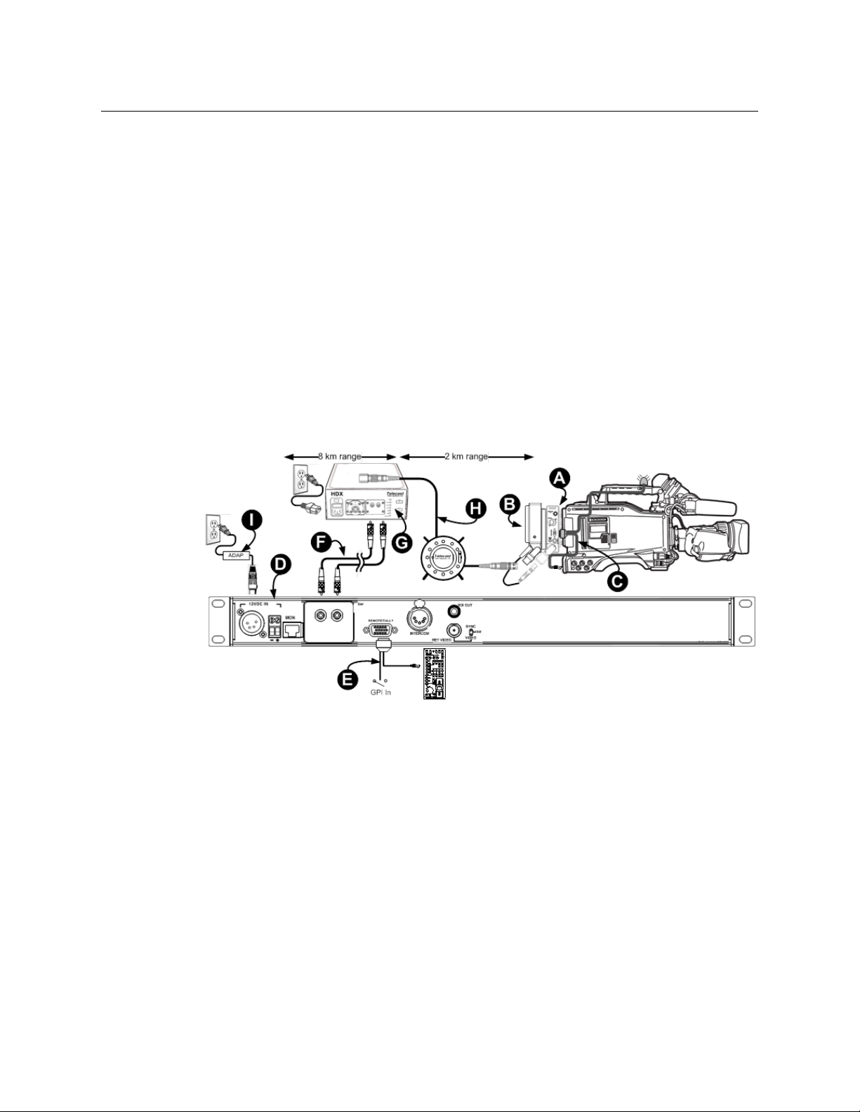
Fig. 1-1: CopperHead System Using PowerPlus and HDX
The first part of the fiber run can be made via “dry” tactical or infrastructure fiber, after
which the HDX power supply is placed in line to provide a powered SMPTE hybrid fiber
cable for the camera. Such a system is typically configured as shown in Figure 1-1 and
includes the following components:
A. Camera Unit
B. PowerPlus
C. CHCR camera remote cable
D. DC-powered Base Station*.
E. CHBR base remote cable
F. Tactical fiber or Infrastructure fiber run
G. HDX Power Supply
H.SMPTE 311M hybrid fiber optic cable
I. ADAP 12VDC power supply
The Base Station can be separated from the HDX power supply on “dry fiber” (F) by more
than nine kilometers (5.6 miles) , where powered hybrid cable (H) can be run to the camera
for another two km (1.2 miles).
2
Page 7

Optical Fiber Safety
Never look directly into the end of the optic fiber while either end of the system is
operating.
Always use cable connector caps when the cables are not connected. This protects the
connector from damage and the unlikely event of exposure to an operating optical link.
Keeping the caps in place when the connectors are not in use will prevent dirt and dust
from entering the connector and degrading the performance of the optical link.
Power Fuses
The HDX is equipped with two fuses located next to the AC Power receptacle on the front
of the unit. Refer to section HDX Fuse Holder on page 15 for specific fuse and location
information.
Never operate the HDX without properly installed and rated fuses. Severe electrical and
heat damage could result as well as personal injury or death.
PowerPlus 3000
User Guide
3
Page 8

About PowerPlus 3000
Power Fuses
4
Page 9

Installation and Mounting
This chapter explains how to install and mount the PowerPlus 3000 device and how to
attach the power supply and camera unit.
Installing HDX into HDX-FR2 . . . . . . . . . . . . . . . . . . . . . . . . . . . . . . . . . . . . . . . . . . . . . . . . . . . . . . . . . . . 6
Mounting the PowerPlus . . . . . . . . . . . . . . . . . . . . . . . . . . . . . . . . . . . . . . . . . . . . . . . . . . . . . . . . . . . . . . 7
Connecting the HDX Power Supply and Camera Unit . . . . . . . . . . . . . . . . . . . . . . . . . . . . . . . . . . . 8
5
Page 10
Installation and Mounting
Installing HDX into HDX-FR2
Installing HDX into HDX-FR2
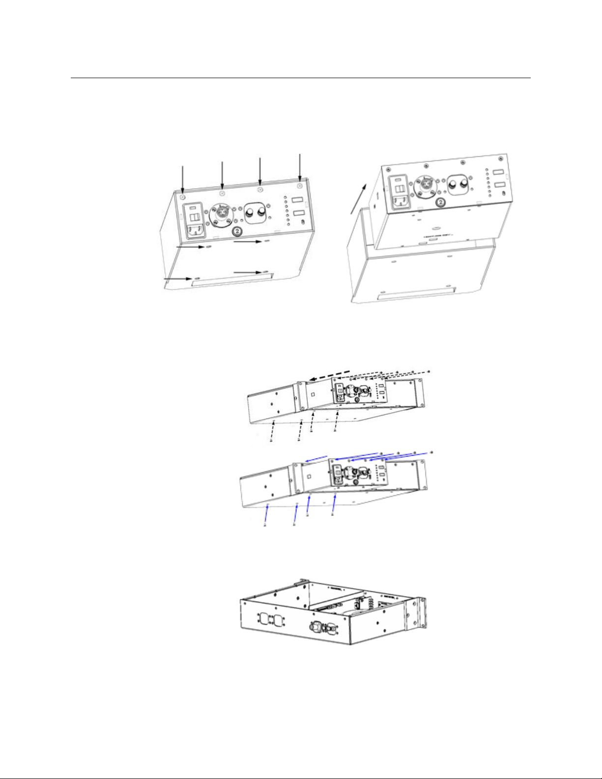
To install the HDX into the rack-mountable HDX-FR2 enclosure
1 Remove the eight screws and slide the HDX electronic module out of the sheath.
Fig. 2-1: Removing HDX screws and removing the sheath
2 Slide the HDX module into the FR2 frame and reinstall the eight screws as shown in
Figure 2-2.
Fig. 2-2: Installing HDX in FR2 Frame
3 The fiber connectors can be relocated to the rear of the frame, as shown in Figure 2-3.
Fig. 2-3: Fiber Connectors on rear of HDX Frame
6
Page 11

Mounting the PowerPlus
When mounting the CopperHead Camera Unit & PowerPlus, always position the camera so
that the battery mounting plate at the rear of the camera is easy to access. Ensure that the
camera is well supported and stable. If a battery is mounted, remove it.
PowerPlus 3000
User Guide
Fig. 2-4: Mounting the PowerPlus Unit to the CopperHead Camera Unit
To mount the camera unit
1 Attach the CopperHead Camera Unit (A) to the camera's battery mounting plate (B).
The mounting is mechanically identical to attaching a battery to the camera.
2 Mount the PowerPlus (C) to the CopperHead Camera Unit battery mounting plate (D)
exactly as you would mount a battery to the camera.
3 Connect the PowerPlus dongle (E) to the fiber optic swivel F on Camera Unit (A).
Connect the SMPTE hybrid cable connector (G) from the HDX to the SMPTE receptacle
(H) on the PowerPlus.
7
Page 12

Installation and Mounting
Connecting the HDX Power Supply and Camera Unit
Connecting the HDX Power Supply and Camera Unit
Mount the PowerPlus (C) to the CopperHead Camera Unit (A) as shown in Mounting the
PowerPlus on page 7, being sure to plug the PowerPlus' tactical fiber dongle (E) into the
swivel-mounted fiber connector (F) on Camera Unit (A).
Fig. 2-5: SMPTE Hybrid Fiber between the HDX Power Supply and Camera Unit
• Connect dry (unpowered) fiber cable (J) between the fiber connector(s) (K) on
Base Station (I) and the "dry" fiber connector(s) (L) on the HDX Power Supply (M).
• Connect the HDX Power Supply (M) to AC Mains (N).
• Connect a length of hybrid fiber cable (O) between the HDX Power Supply (M) and the
swivel-mounted hybrid fiber connector H on the PowerPlus (C).
The hybrid fiber cable can be equipped with either SMPTE 304M (G) or OpticalCON*
connectors. The camera and CopperHead Camera Unit will be powered via the hybrid cable
(O) by the PowerPlus (C).
Note: At HDX power levels (>95VDC), the powered OpticalCON
connector is suitable for indoor (studio) camera links only (see
PowerPlus Connectors on page 21).
8
Page 13

PowerPlus 3000 Components
This chapter describes the components included with the PowerPlus 3000 system.
Camera Power Adaptor . . . . . . . . . . . . . . . . . . . . . . . . . . . . . . . . . . . . . . . . . . . . . . . . . . . . . . . . . . . . . . . 10
HDX Power Supply . . . . . . . . . . . . . . . . . . . . . . . . . . . . . . . . . . . . . . . . . . . . . . . . . . . . . . . . . . . . . . . . . . . 13
HDX Status Indicators . . . . . . . . . . . . . . . . . . . . . . . . . . . . . . . . . . . . . . . . . . . . . . . . . . . . . . . . . . . . . . . . 14
HDX Fuse Holder . . . . . . . . . . . . . . . . . . . . . . . . . . . . . . . . . . . . . . . . . . . . . . . . . . . . . . . . . . . . . . . . . . . . . 15
9
Page 14

PowerPlus 3000 Components
Low Profile Heat Sink High Profile Heat Sink
Camera Power Adaptor
Camera Power Adaptor
The CopperHead PowerPlus 3000 power adaptor with standard "Low Profile" heat sink
(Figure 3-1) provides a continuous 100 watts of 12VDC power (150 watts momentary) and
fiber cable signal connectivity from Base Station to the Camera. It also provides an external
power feed of 12VDC and optionally 24VDC for external accessories.
The PowerPlus can be equipped with a High Profile heat sink (Figure 3-1) for power
requirements up to 150 Watts.
The PowerPlus unit is equipped with a fixed tactical fiber dongle that can be terminated
with either an OpticalCON plug, an SMPTE 304M plug, or an MX plug. This dongle plugs into
the complimentary swivel of the CopperHead Camera Unit.
The PowerPlus is connected to the HDX power supply using Hybrid fiber cable with SMPTE
304 connectors. See Mounting the PowerPlus on page 7.
The distance between the HDX power adaptor and the camera can be up to 2 km (1.2 miles)
using Hybrid fiber cable and the distance between the HDX power adaptor and Base
Station can be up to 8 km (4.3 miles).
Fig. 3-1: PowerPlus 3000with Heat Sinks mounted to CopperHead Camera Unit
10
Page 15

PowerPlus 3000
PowerPlus 3000 LED Indicators
PowerPlus 3000 Connectors
User Guide
Fig. 3-2: PowerPlus 3000 LED Indicators and Connectors
No. Description No. Description
PowerPlus 3000 LED Indicators
1 24 Volt DC "A":
24VDC is available on connector at
v Power In
2 Power In:
Power is being received from the
4 Auxilliary +12 Volt Output:
12VDC is being supplied to 4-pin XLR
connector V
5 24 Volt DC "B":
24VDC is available on connector X
HDX power supply
• Red - initial safety handshaking in
progress, full power not engaged.
• Green - safety handshaking
completed, full power being
received from HDX power supply.
3 Camera Out:
12VDC is being supplied to the
battery plate
6 Battery Plate:
Used to mount the PowerPlus to the
CopperHead Camera Unit
(Anton/Bauer or V-Mount)
PowerPlus 3000 Connectors
7 Heat Sink:
• LP- Low Profile Heat Sink rated for
100 Watts (shown)
11 Tactical Fiber Dongle:
Fixed tactical fiber cable connects to
the CopperHead Camera Unit.
• HP - High Profile Heat Sink rated
for 150 Watts (not shown)
11
Page 16

PowerPlus 3000 Components
Camera Power Adaptor
No. Description No. Description
8 12 Volt Auxiliary Output:
9 24 Volt Auxiliary Output B:
10 24 Volt Auxiliary Output A:
4-Pin XLR output connector for 12
Volt accessories
3-pin connector for 24 Volt
accessories.
3-pin connector for 24 Volt
accessories
12 SMPTE Swivel:
Adjustable swivel for Hybrid Fiber
receptacle am.
13 Hybrid Fiber Receptacle (SMPTE
304M shown):
Connect the SMPTE hybrid cable here.
This cable connects to the HDX.
Available with the following
termination:
• SMPTE 304M plug (shown)
• OpticalCON Connector*
14 Tactical Fiber Connector (MX shown):
Dry fiber connector at the end of the
dongle, matching the connector on
the swivel of the mating CopperHead
Camera Unit.
Available with the following
termination:
• MX plug (shown)
• OpticalCON Connector ("dry")
• SMPTE 304M plug ("dry")
*At HDX power levels (>95VDC), the powered OpticalCON connector is suitable for indoor
(studio) camera links only (see PowerPlus Fiber Connectors on page 23).
12
Page 17

HDX Power Supply
The HDX Power Supply unit is required when using the PowerPlus Camera Adaptor. The
HDX can be used as a free-standing unit or rack mounted, using the HDX-FR-2 for mounting
one or two HDX units.
The HDX unit sends power via a SMPTE hybrid fiber cable to the PowerPlus, where it
is converted to 12VDC and optionally to 24VDC). See Connecting the HDX Power Supply
and Camera Unit on page 8 for details on connecting the HDX to a CopperHead system.
PowerPlus 3000
User Guide
Fig. 3-3: HDX Front Panel and Stand-alone unit with handles
The HDX has five features:
• A: AC Power Input Module and Switch and Fuse Holder: Power Switch and connector
for AC Mains.
Note: Removable fuse module must be set for correct voltage
(110VAC or 220VAC). See HDX Fuse Holder on page 15.
• B: "Wet" Hybrid Fiber Connector: the SMPTE hybrid cable connects from here to the
PowerPlus at the camera. Two options are available:
• B1 SMPTE 304M connector (standard)
• B2 OpticalCON connector (indoor use only)*
• C: "Dry" Fiber connector(s): the CopperHead Base Station is connected here. This
interface can be equipped with a variety of fiber connectors:
• C1 Two ST connectors
• C2 OpticalCON connector
•C3 MX connector
• D: Status Indicators: these indicators show the status of the HDX's power system. For
more details, see
• E: HDX Integrated Handle: stand-alone unit can be carried or hung from this robust
handle.
Important Note on page 24.
*At HDX power levels (>95VDC), the powered OpticalCON connector is suitable for indoor
(studio) camera links only (see
Important Note on page 24).
13
Page 18

PowerPlus 3000 Components
HDX Status Indicators
HDX Status Indicators
Fig. 3-4: HDX Displays
• 1- AC IN - MAINS: AC Input power is
present
• 2 - DC HV ENABLE: DC "Sense" voltage
from PowerPlus is present
• 3 - AC HV ENABLE: AC "Sense" voltage
from PowerPlus is present (not used with
PowerPlus)
• 4 - HV Present: DC voltage is available on
Hybrid connector
• 5 - CABLE OPEN: There is no electrical
connection to the PowerPlus unit.
• 6 - CABLE SHORT: A short circuit is
detected in the SMPTE Hybrid Cable.
High voltage is disabled until this
condition is corrected
• 7 - REMOTE PWR ENABLE: Not used
with PowerPlus
• 8 - LOAD TYPE: Indicates the type of
load or camera being used:
• N/A - No load detected
• PWR+ - PowerPlus detected
Note: Upon power Up, this displays
firmware version for two seconds
• 9 - Optical Power: Not used with
PowerPlus.
• 10 - Local Remote: Not used with
PowerPlus.
The LED Status Indicators will illuminate under "Normal" and Error" conditions as shown:
Normal Not Connected Cable Short
AC IN Green Green Green
DC HV ENABLE Green Red Red
AC HV ENABLE Unlit Red Red
HV PRESENT Green Unlit Unlit
CABLE OPEN Unlit Red Unlit
CABLE SHORT Unlit Unlit Red
REMOTE PWR ENABLE Unlit Unlit Unlit
14
Page 19

HDX Fuse Holder
HDX Fuse Holder Using Short Fuses
The correct fuses must be used for the appropriate AC Mains power supply:
• 115VAC: Fuse 3A, "Slo-Blo"
• 220VAC: Fuse 2A, "Slo-Blo"
HDX Fuse Holder must be flipped if switching between 110VAC and 220VAC, as shown in
Figure 3-5.
PowerPlus 3000
User Guide
Fig. 3-5: HDX Fuse Holder
The fuse holder can hold two 1/4" x 1-1/4" (3AG) or shorter 5 x 20mm (metric) fuses. If using
the shorter fuses, be sure the fuse is positioned "forward" towards the HDX power supply,
as shown in Figure 3-5.
15
Page 20

PowerPlus 3000 Components
HDX Fuse Holder
16
Page 21

Specifications
Electro-Optical
Fiber Compatibility
Powered Fiber Between HDX and PowerPlus
Hybrid Fiber/Copper Cable....................................................................SMPTE 311M cable
Hybrid Optical Connector Options
Standard ............................................................................................................. SMPTE 304M
Special Order...................................................................................................... OpticalCON§
Dry Fiber
PowerPlus (“Dongle” to CopperHead).................... SMPTE 304M, OpticalCON, or MX
HDX (to CopperHead Base Station) .................................. Dual STs, OpticalCON, or MX
Power
PowerPlus
Input (from HDX): . ......................................................................................................... 320VDC
Output:
Low Profile ........................................ 100W continuous (150 momentary) @14 VDC
High Profile............................................................................. 150W continuous @14 VDC
12VDC Power Connector. .......................................................... Battery Plate, 4-Pin XLR
24VDC Power Connector (optional) ...........................................................3-pin Fischer
HDX:
Power Req ...................................................................... 110-120/220-240 VAC, 50 to 60Hz
Power Consumption..................................................................... 250 watts max @120VAC
Safety Interlock .................................................................32VAC Pilot, 5VDC Sense return
Main Output (to PowerPlus): ..................................................................................... 320VDC
Distance Limit *see note below
HDX w/PowerPlus ............................................ 2km (6562 ft.): 100W Cont./150W Peak*
Mechanical/Environmental
Dimensions (HxWxD)
PowerPlus LP (100W) ............................................................................................ 5" x 6" x 2.5"
PowerPlus HP (150W) ........................................................................................... 5" x 6" x 3.7"
HDX......................................................................................................................3.5" x 8.25" x 10"
FR-2 ............................................................. 3.5" x 16.5" x 12" (2RU high, rack mountable)
Wei ght
PowerPlus.......................................................................................... LP: 2.3 lb.......HP: 2.5 lb.
HDX.................................................................................................................................... 10.5 lb.
17
Page 22

Specifications
Temperature Range ................................................................................................-25° to +55°C
Humidity Range ....................................................................0 to 95% RH, Noncondensing
§ At HDX power levels (>95VDC), the powered OpticalCON connector is suitable for
indoor (studio) camera links only, under specific conditions according to IEC 60664-1
“Pollution Degree 1,” where there is zero humidity, zero expected condensation and zero
conductive pollution. The powered OpticalCON connector is NOT suitable for outdoor/field
use where humidity/condensation may be present. For detailed information ask for the
Neutrik White Paper "OpticalCON Camera Applications Using Hybrid SMPTE Cables Where
Voltage Exceeds 50V".
* The maximum cable length varies due to optical loss that can depend on cable quality,
dirt/dust/contamination on connectors, and the number of cable connectors. When using
hybrid cable for camera power, the size and condition of the hybrid cable, as well as the
power draw of the camera, lens, viewfinder, and other accessories are also factors.
18
Page 23

Grass Valley Technical Support
For technical assistance, please contact the Grass Valley Technical Support center nearest
you:
Contact Us
Americas
Office hours: 9:00 a.m. – 9:00 p.m. (EST)
Telephone: 1-800-224-7882
Fax: +1 514 335 1614
E-mail: support@miranda.com
Europe, Middle East, Africa, UK
Office hours: 9:00 a.m. – 6:00 p.m. (GMT)
Telephone: +44 118 952 3444
Fax: +44 118 952 3401
E-mail: eurotech@miranda.com
France
Office hours: 9:00 a.m. – 5:00 p.m. (GMT+1)
Telephone: +33 1 55 86 87 88
Fax: +33 1 55 86 00 29
E-mail: eurotech@miranda.com
Corporate Head Office
Asia
Office hours: 9:00 a.m. – 6:00 p.m. (GMT+8)
Telephone: +852 2539 6987
Fax: +852 2539 0804
E-mail: asiatech@miranda.com
China
Office hours: 9:00 a.m. – 6:00 p.m. (GMT+8)
Telephone: +86 10 5873 1814
E-mail: asiatech@miranda.com
Malaysia
Telephone: +60 3 2247 1808
EMERGENCY After Hours (Global)
Toll Free: 1-800-224-7882 (US and Canada)
Telephone: +1 514 333 1772
Grass Valley
3499 Douglas-B.-Floreani
St-Laurent, Quebec H4S 2C6
Canada
Telephone: +1 514 333 1772
Fax: +1 514 333 9828
Web: www.miranda.com
Page 24

Parts and Accessories
This appendix describes the various parts and accessories for the PowerPlus 3000 system.
Electrical Connectors . . . . . . . . . . . . . . . . . . . . . . . . . . . . . . . . . . . . . . . . . . . . . . . . . . . . . . . . . . . . . . . . . 21
Fiber Connectors . . . . . . . . . . . . . . . . . . . . . . . . . . . . . . . . . . . . . . . . . . . . . . . . . . . . . . . . . . . . . . . . . . . . . 23
PowerPlus 3000/HDX Parts & Accessories . . . . . . . . . . . . . . . . . . . . . . . . . . . . . . . . . . . . . . . . . . . . . 25
Part Numbering Matrix . . . . . . . . . . . . . . . . . . . . . . . . . . . . . . . . . . . . . . . . . . . . . . . . . . . . . . . . . . . . . . . 26
HDC Part Numbering Matrix . . . . . . . . . . . . . . . . . . . . . . . . . . . . . . . . . . . . . . . . . . . . . . . . . . . . . . . . . . 26
20
Page 25

Electrical Connectors
Electrical Connectors
PowerPlus Connectors
PowerPlus 12VDC Output Connector
PowerPlus #8
XLR 4-pin Female
(Ext View)
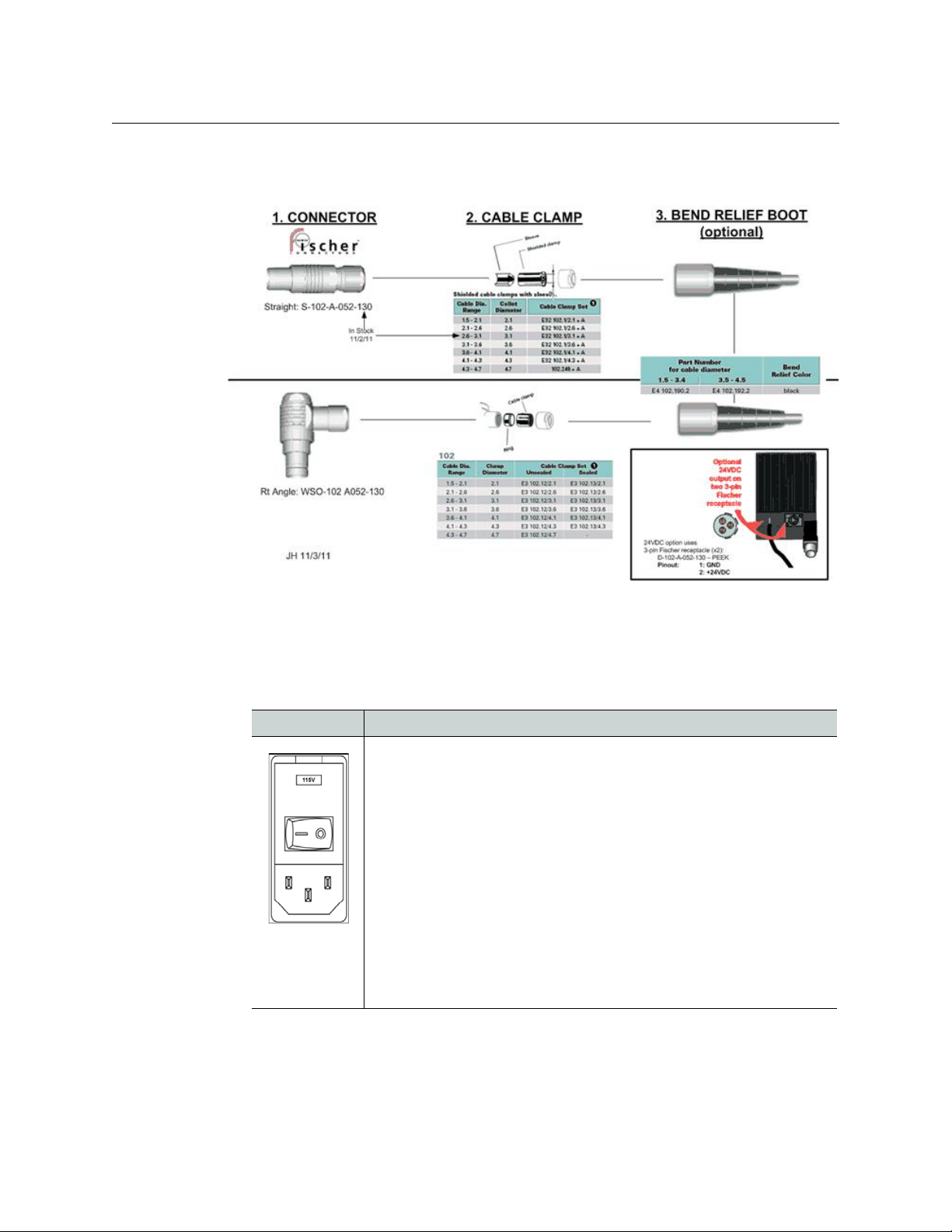
PowerPlus 24VDC Output Connectors (optional)
Pin Signal
1GND
2Unused
3Unused
4
+Power12VDC
1GND
PowerPlus # 9 & #10
Fischer 3-pin Female
(Ext View)
2+24 VDC
3Unused
Mating connectors:
• Fischer S-102-A-052-130 (straight)
• Fischer WSO-102-A0520130 (right angle)
21
Page 26
HDX Power Supply Connector
PowerPlus 3000
User Guide
Fig. A-1: 24VDC Connectors – compatible plugs
HDX Power Supply Connector
AC Power Input Connector
Item Description
Panel Mounted AC Power Receptacle: 110/220 VAC
Fuses: the removable fuse holder can hold two 1/4” x 1-1/4” (3AG) or
shorter 5 x 20mm (metric) fuses.
• 120 VAC: Two 3 amp slo-blo fuses
• 220 VAC: Two 2 amp slo-blo fuses
NOTE:Removablefusemodulemustbesetforcorrectvoltage(110VAC
or220VAC). See HDX Fuse Holder on page 15.
AC Power
Interface
IEC C14
receptacle
22
Page 27

Fiber Connectors
Fiber Connectors
PowerPlus Fiber Connectors
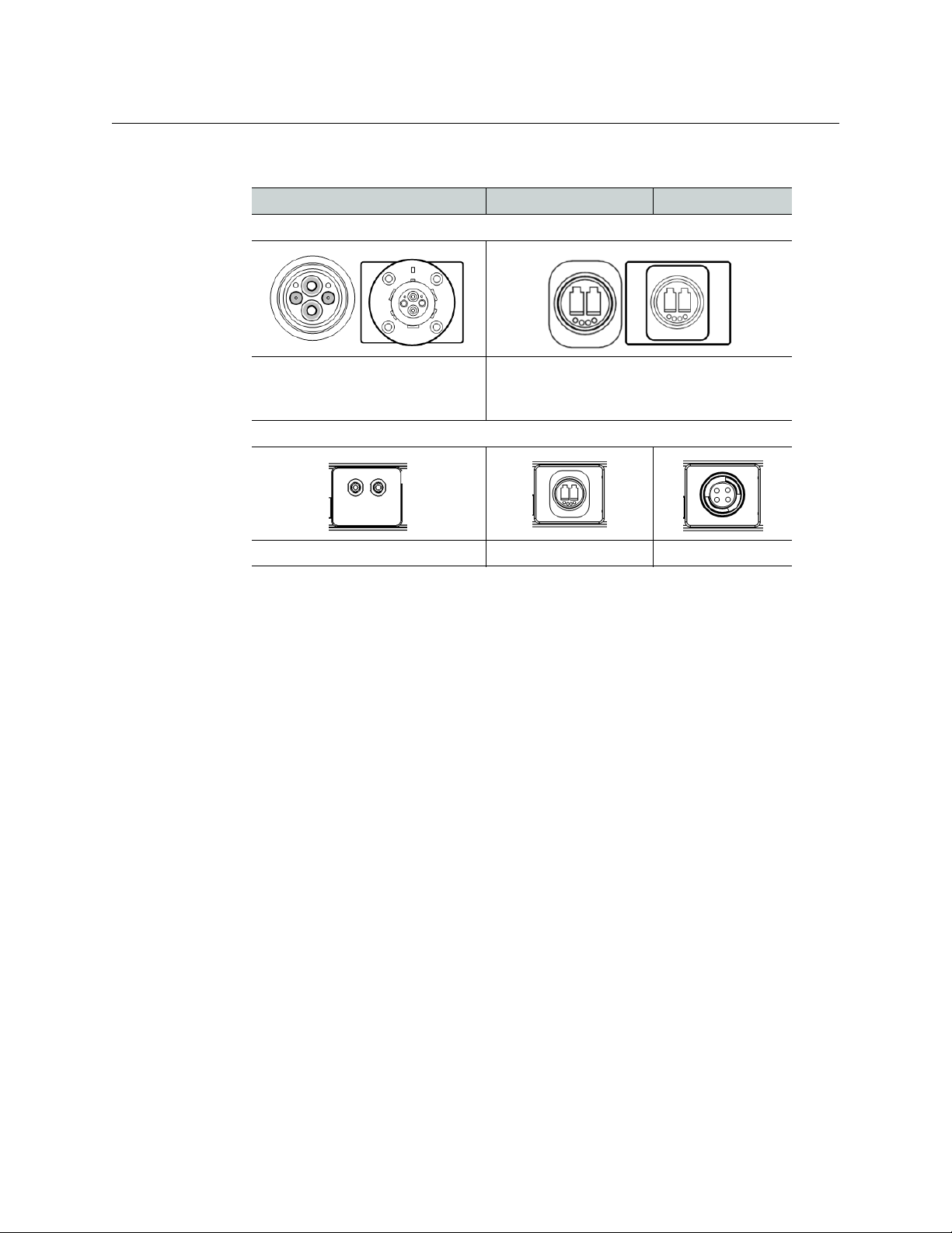
PowerPlus Powered Fiber Connector Options (Swivel)
SMPTE 304M Receptacle OpticalCON Receptacle
PowerPlus Unpowered Fiber Connector Options (Dongle)
Indoor only: Pollution Degree 1
(see Important Note on page 24)
MX Plug
OpticalCON Plug
SMPTE 304M Plug
23
Page 28
HDX Fiber Connectors
HDX Powered Fiber Connector Options
SMPTE 304M Panel Mounted Plug OpticalCON Receptacle
HDX Unpowered Fiber Connector
PowerPlus 3000
User Guide
Indoor only: Pollution Degree 1
(see Important Note on page 24).
Important Note
Regarding Use of Powered OpticalCON connector with PowerPlus & HDX System
At HDX power levels (>95VDC), the powered OpticalCON connector is suitable for indoor
(studio) camera links only, under specific conditions according to IEC 60664-1 “Pollution
Degree 1,” where there is zero humidity, zero expected condensation and zero conductive
pollution.
The powered OpticalCON connector is NOT suitable for outdoor/field use where
humidity/condensation may be present. For detailed information, ask for the Neutrik White
Paper "OpticalCON Camera Applications Using Hybrid SMPTE Cables Where Voltage
Exceeds 50V".
ST Receptacles OpticalCON Receptacle MX Receptacle
24
Page 29

PowerPlus 3000/HDX Parts & Accessories
PowerPlus 3000/HDX Parts & Accessories
PWRPLS3
Long Distance "PowerPlus" Camera Adaptor for use with HDX (specify LP or HP).
Fig. A-2: PWRPLS3
HDX
HDX-FR-2
Power Supply for PowerPlus Power Adaptor.
Fig. A-3: HDX
Rack mount frame kit for one or two2 HDX units (HDX power supplies not included).
25
Fig. A-4: HDX-FR-2
Page 30

Part Numbering Matrix
Part Number Description
Product PWRPLS3
Power Output 12 12VDC output, 100 Watts Max, Low Profile Heat Sink.
Dongle MX MX Mini Expanded Beam
Battery Mount V V-Shoe (Sony)
PowerPlus 3000
User Guide
12-HP 12VDC output, 150 Watts Max, High Profile Heat Sink
(High Power/High Profile).
12-24 12VDC and 24VDC output, 100 Watts Max, Low Profile
Heat Sink
12-24-HP 12-24-HP 12VDC and 24VDC output, 150 Watts Max,
High Profile Heat Sink (High Power/High Profile).
NEU OpticalCON Duo, unpowered
304 SMPTE 304M male, unpowered
AB Gold Mount (Anton/Bauer)
HDC Part Numbering Matrix
Part Number Description
Product HDX
Powered Connector LM SMPTE 304M female - Lemo
Dry Connector ST 2 STs
Special Options RC Remote camera power shutoff control
FIS SMPTE 304M female - Fischer
LC 2 LCs
MX MX Expanded Beam (2 channels only)
NEU Neutrik OpticalCON Duo (dry)
NEU4 Neutrik OpticalCON Quad (2 channels only)
LD3 Grass Valley LDK Cameras only
PAN Panasonic Cameras only
HIT-RC Hitachi Cameras only
26
Page 31

HDC Part Numbering Matrix
27
 Loading...