

Page 1

Protocol Manual
MODEL 2200/3000/4000
DIGITAL PRODUCTION SWITCHERS
TP0350-03 A1
FIRST PRINTNG: MAY 1997
5.1software release
and later
Page 2

Telephone Numbers
North America
(800) 547-8949
Fax: (916) 478-3181 (changes to
(530) 478-3181 as of 11/1/97)
Brazil
55 11 37 41 8422
Mexico
52 5 666 6333
Hong Kong
852 259 355 00
Elsewhere
Distributor or sales office from
which equipment was purchased.
Web Addresses
Grass Valley Email Support
GVGSERVICE@tek.com
Grass V alley Products
Customer Service Information
Telephone Support
Grass Valley is committed to providing the most responsive and professional product support available anywhere. We have a fully staffed, highly
trained support team ready to respond to anything from a simple question
to an emergency repair. If you need assistance, contact one of the Customer Support numbers listed at left.
E-mail Support
All Grass Valley customers receive free e-mail support. You may communicate your questions and other support needs to Grass Valley at the
e-mail address listed at left.
T ektronix on the W orld Wide Web
Tektronix maintains a site on the World Wide Web (WWW) which contains
customer support documents and new product information. New and updated information is always being added, so check the site frequently. The
site address is listed at left. Grass Valley Products maintains a page on TektronixÕ web site which can be accessed directly via the listed address.
Grass Valley W eb Page
http://www.tek.com/Grass_V alley
Tektronix W eb Site
http://www.tek.com
Postal Addresses
Mail
Tektronix Grass Valley Products
P.O. Box 1114
Grass Valley, CA 95945
Shipping
Tektronix Grass Valley Products
400 Providence Mine Rd.,
Nevada City, CA 95959
o
o
Copyright © Tektronix, Inc. All rights reserved. Printed in U.S.A.
o
o
Tektronix products are covered by U.S. and foreign patents, issued and pending. Information
o
in this publication supersedes that in all previously published material. Specifications and
o
price change privileges reserved. TEKTRONIX, TEK, Grass Valley Group, Borderline,
o
E-MEM, TEN-X, Wavelink, and are registered trademarks, and Air Link, Auto Match,
o
Doubletake, E-Disk, Eagle V, Emphasys, EZ-Link, 409, Grass Valley, Horizon, Jogger, Kaden-
o
za, Kaleidoscope, K-Mask, Key-Layer, Key-Link, Krystal, MASTER System, Master 21, MAX,
o
Omni-Key, Performer, Programmed Motion, Silhouette, Softset, SqueezeBack, Streamline,
o
Super Edit, TEN-20, 20-TEN, Trace, TrailBlazer, VideoDesktop, Flex-Time, and XEDL are
o
trademarks of Tektronix, Inc. P.O. Box 1000 Wilsonville, OR 97070-1000 U.S.A.
o
o
The information in this manual is furnished for informational use only, is subject to change
o
without notice, and should not be construed as a commitment by Tektronix, Inc. Tektronix
o
assumes no responsibility or liability for any errors or inaccuracies that may appear in this
o
publication.
o
o
Tektronix, Inc., Video and Networking Division, P.O. Box 1114 Grass Valley, California
o
95945 U.S.A.
Page 3

Contents
Section 1 — Introduction
General Description . . . . . . . . . . . . . . . . . . . . . . . . . . . . . . . . . . . . . . . . . . . . . . . . . . 1-1
Manual Contents . . . . . . . . . . . . . . . . . . . . . . . . . . . . . . . . . . . . . . . . . . . . . . . . . . . . . 1-1
Editor Connectivity . . . . . . . . . . . . . . . . . . . . . . . . . . . . . . . . . . . . . . . . . . . . . . . . . . 1-2
Editor Port Jumpers . . . . . . . . . . . . . . . . . . . . . . . . . . . . . . . . . . . . . . . . . . . . . . . . . . 1-3
Model 3000 . . . . . . . . . . . . . . . . . . . . . . . . . . . . . . . . . . . . . . . . . . . . . . . . . . . . . . 1-3
Communication Standard . . . . . . . . . . . . . . . . . . . . . . . . . . . . . . . . . . . . . . 1-3
Termination . . . . . . . . . . . . . . . . . . . . . . . . . . . . . . . . . . . . . . . . . . . . . . . . . . 1-3
Model 2200/4000 . . . . . . . . . . . . . . . . . . . . . . . . . . . . . . . . . . . . . . . . . . . . . . . . . 1-4
Communication Standard . . . . . . . . . . . . . . . . . . . . . . . . . . . . . . . . . . . . . . 1-4
Termination . . . . . . . . . . . . . . . . . . . . . . . . . . . . . . . . . . . . . . . . . . . . . . . . . . 1-4
Serial Data Word Description . . . . . . . . . . . . . . . . . . . . . . . . . . . . . . . . . . . . . . . . . . 1-5
Editor Enable Pushbutton . . . . . . . . . . . . . . . . . . . . . . . . . . . . . . . . . . . . . . . . . . . . . 1-6
System Performance . . . . . . . . . . . . . . . . . . . . . . . . . . . . . . . . . . . . . . . . . . . . . . . . . . 1-6
Section 2 — Editor Protocol
Serial Communications . . . . . . . . . . . . . . . . . . . . . . . . . . . . . . . . . . . . . . . . . . . . . . . 2-1
Editor Protocol Access . . . . . . . . . . . . . . . . . . . . . . . . . . . . . . . . . . . . . . . . . . . . . . . . 2-1
Break Character . . . . . . . . . . . . . . . . . . . . . . . . . . . . . . . . . . . . . . . . . . . . . . . . . . 2-2
Address Byte . . . . . . . . . . . . . . . . . . . . . . . . . . . . . . . . . . . . . . . . . . . . . . . . . . . . . 2-4
Command/Message Block Structure . . . . . . . . . . . . . . . . . . . . . . . . . . . . . . . . . . . 2-5
Byte Count . . . . . . . . . . . . . . . . . . . . . . . . . . . . . . . . . . . . . . . . . . . . . . . . . . . . . . . 2-5
Effects Address Byte . . . . . . . . . . . . . . . . . . . . . . . . . . . . . . . . . . . . . . . . . . . . . . 2-5
Command Code Byte . . . . . . . . . . . . . . . . . . . . . . . . . . . . . . . . . . . . . . . . . . . . . . 2-6
Read Commands . . . . . . . . . . . . . . . . . . . . . . . . . . . . . . . . . . . . . . . . . . . . . . 2-6
Write Commands . . . . . . . . . . . . . . . . . . . . . . . . . . . . . . . . . . . . . . . . . . . . . . 2-6
Status and Data Replies . . . . . . . . . . . . . . . . . . . . . . . . . . . . . . . . . . . . . . . . . . . . . . . 2-7
Error Detection . . . . . . . . . . . . . . . . . . . . . . . . . . . . . . . . . . . . . . . . . . . . . . . . . . . . . . 2-8
Transmission Errors . . . . . . . . . . . . . . . . . . . . . . . . . . . . . . . . . . . . . . . . . . . . . . . 2-8
Protocol Errors . . . . . . . . . . . . . . . . . . . . . . . . . . . . . . . . . . . . . . . . . . . . . . . . . . . 2-9
iii
Page 4

Model 2200/3000/4000 Protocols
Section 3 — Editor Interface Commands
Introduction . . . . . . . . . . . . . . . . . . . . . . . . . . . . . . . . . . . . . . . . . . . . . . . . . . . . . . . . . 3-1
Editor Interface Commands . . . . . . . . . . . . . . . . . . . . . . . . . . . . . . . . . . . . . . . . . . . 3-1
Revision History . . . . . . . . . . . . . . . . . . . . . . . . . . . . . . . . . . . . . . . . . . . . . . . . . . . . . 3-3
Application Examples . . . . . . . . . . . . . . . . . . . . . . . . . . . . . . . . . . . . . . . . . . . . . . . . 3-4
Example 1: Bringing the Editor Interface into a Ready State . . . . . . . . . . . . . 3-4
Example 2: How to Set Crosspoint #6, A Row, Mix/Effects 2 . . . . . . . . . . . 3-4
ALL STOP (F2) Command (Version 5.1 and Later) . . . . . . . . . . . . . . . . . . . . . . . . 3-5
Effects Addresses . . . . . . . . . . . . . . . . . . . . . . . . . . . . . . . . . . . . . . . . . . . . . . . . . 3-5
Crosspoint Bus (C1) Command (PGM/BKGD A/AUX) . . . . . . . . . . . . . . . . . . . 3-6
Effects Addresses . . . . . . . . . . . . . . . . . . . . . . . . . . . . . . . . . . . . . . . . . . . . . . . . . 3-6
Crosspoint Numbers . . . . . . . . . . . . . . . . . . . . . . . . . . . . . . . . . . . . . . . . . . . . . . 3-7
Crosspoint Bus (C2) Command (PST/BKGD B) . . . . . . . . . . . . . . . . . . . . . . . . . . 3-8
Effects Addresses . . . . . . . . . . . . . . . . . . . . . . . . . . . . . . . . . . . . . . . . . . . . . . . . . 3-8
Crosspoint Numbers . . . . . . . . . . . . . . . . . . . . . . . . . . . . . . . . . . . . . . . . . . . . . . 3-8
Crosspoint Bus (C3) Command (KEY 1/DSK 1) . . . . . . . . . . . . . . . . . . . . . . . . . . 3-9
Effects Addresses . . . . . . . . . . . . . . . . . . . . . . . . . . . . . . . . . . . . . . . . . . . . . . . . . 3-9
Crosspoint Numbers . . . . . . . . . . . . . . . . . . . . . . . . . . . . . . . . . . . . . . . . . . . . . . 3-9
Crosspoint Bus (C4) Command (KEY 2/DSK 2) . . . . . . . . . . . . . . . . . . . . . . . . . 3-10
Effects Addresses . . . . . . . . . . . . . . . . . . . . . . . . . . . . . . . . . . . . . . . . . . . . . . . . 3-10
Crosspoint Numbers . . . . . . . . . . . . . . . . . . . . . . . . . . . . . . . . . . . . . . . . . . . . . 3-10
Crosspoint Bus (E2) Command (PVW) . . . . . . . . . . . . . . . . . . . . . . . . . . . . . . . . . 3-11
Effects Addresses . . . . . . . . . . . . . . . . . . . . . . . . . . . . . . . . . . . . . . . . . . . . . . . . 3-11
Crosspoint Numbers . . . . . . . . . . . . . . . . . . . . . . . . . . . . . . . . . . . . . . . . . . . . . 3-11
Crosspoint Bus (E3) Command (MASK) . . . . . . . . . . . . . . . . . . . . . . . . . . . . . . . . 3-12
Effects Addresses . . . . . . . . . . . . . . . . . . . . . . . . . . . . . . . . . . . . . . . . . . . . . . . . 3-12
Crosspoint Numbers . . . . . . . . . . . . . . . . . . . . . . . . . . . . . . . . . . . . . . . . . . . . . 3-12
Pushbutton Select and Control (C6, C7 and FB) Commands . . . . . . . . . . . . . . . 3-13
Effects Addresses . . . . . . . . . . . . . . . . . . . . . . . . . . . . . . . . . . . . . . . . . . . . . . . . 3-13
Pushbutton Numbers . . . . . . . . . . . . . . . . . . . . . . . . . . . . . . . . . . . . . . . . . . . . 3-14
Write Wipe Pattern (C8) Command . . . . . . . . . . . . . . . . . . . . . . . . . . . . . . . . . . . 3-21
Effects Addresses . . . . . . . . . . . . . . . . . . . . . . . . . . . . . . . . . . . . . . . . . . . . . . . . 3-21
Wipe Numbers . . . . . . . . . . . . . . . . . . . . . . . . . . . . . . . . . . . . . . . . . . . . . . . . . . 3-21
Write Transition Mode (CA) Command . . . . . . . . . . . . . . . . . . . . . . . . . . . . . . . . 3-23
Effects Addresses . . . . . . . . . . . . . . . . . . . . . . . . . . . . . . . . . . . . . . . . . . . . . . . . 3-23
Mode Byte . . . . . . . . . . . . . . . . . . . . . . . . . . . . . . . . . . . . . . . . . . . . . . . . . . . . . . 3-23
Write Transition Rate Commands . . . . . . . . . . . . . . . . . . . . . . . . . . . . . . . . . . . . . 3-25
Model 3000-2 and 4000-2B . . . . . . . . . . . . . . . . . . . . . . . . . . . . . . . . . . . . . 3-25
Model 2200-2 . . . . . . . . . . . . . . . . . . . . . . . . . . . . . . . . . . . . . . . . . . . . . . . . 3-25
Model 3000-3 and 4000-2A . . . . . . . . . . . . . . . . . . . . . . . . . . . . . . . . . . . . . 3-26
Transition Rates . . . . . . . . . . . . . . . . . . . . . . . . . . . . . . . . . . . . . . . . . . . . . . . . . 3-26
Write Auto Transition Rate (CC) Command . . . . . . . . . . . . . . . . . . . . . . . . . . . . 3-27
Effects Addresses . . . . . . . . . . . . . . . . . . . . . . . . . . . . . . . . . . . . . . . . . . . . . . . . 3-27
Transition Rate . . . . . . . . . . . . . . . . . . . . . . . . . . . . . . . . . . . . . . . . . . . . . . . . . . 3-27
iv
Page 5

Contents
Write Key Transition Rate (CD) Command . . . . . . . . . . . . . . . . . . . . . . . . . . . . . 3-29
Effects Addresses . . . . . . . . . . . . . . . . . . . . . . . . . . . . . . . . . . . . . . . . . . . . . . . . 3-29
Transition Rate . . . . . . . . . . . . . . . . . . . . . . . . . . . . . . . . . . . . . . . . . . . . . . . . . . 3-29
Write Recall E-MEM Register (DB) Command . . . . . . . . . . . . . . . . . . . . . . . . . . 3-31
Effects Addresses . . . . . . . . . . . . . . . . . . . . . . . . . . . . . . . . . . . . . . . . . . . . . . . . 3-31
Mode Byte . . . . . . . . . . . . . . . . . . . . . . . . . . . . . . . . . . . . . . . . . . . . . . . . . . . . . . 3-32
Registers . . . . . . . . . . . . . . . . . . . . . . . . . . . . . . . . . . . . . . . . . . . . . . . . . . . . . . . 3-34
Bit-Mask Format . . . . . . . . . . . . . . . . . . . . . . . . . . . . . . . . . . . . . . . . . . . . . . . . . 3-34
Write Learn E-MEM Register (DA) Command . . . . . . . . . . . . . . . . . . . . . . . . . . 3-35
Effects Addresses . . . . . . . . . . . . . . . . . . . . . . . . . . . . . . . . . . . . . . . . . . . . . . . . 3-35
Mode Byte . . . . . . . . . . . . . . . . . . . . . . . . . . . . . . . . . . . . . . . . . . . . . . . . . . . . . . 3-36
Registers . . . . . . . . . . . . . . . . . . . . . . . . . . . . . . . . . . . . . . . . . . . . . . . . . . . . . . . 3-36
Bit-Mask Format . . . . . . . . . . . . . . . . . . . . . . . . . . . . . . . . . . . . . . . . . . . . . . . . . 3-37
Write Split Key (E4) Command . . . . . . . . . . . . . . . . . . . . . . . . . . . . . . . . . . . . . . . 3-38
Effects Addresses . . . . . . . . . . . . . . . . . . . . . . . . . . . . . . . . . . . . . . . . . . . . . . . . 3-38
Crosspoint Numbers . . . . . . . . . . . . . . . . . . . . . . . . . . . . . . . . . . . . . . . . . . . . . 3-39
Select ÒLayeredÓ Or ÒStandardÓ (E8) Command . . . . . . . . . . . . . . . . . . . . . . . . . 3-40
Effects Addresses . . . . . . . . . . . . . . . . . . . . . . . . . . . . . . . . . . . . . . . . . . . . . . . . 3-40
Mode Byte . . . . . . . . . . . . . . . . . . . . . . . . . . . . . . . . . . . . . . . . . . . . . . . . . . . . . . 3-40
Data Transfer (5E and DE) Commands . . . . . . . . . . . . . . . . . . . . . . . . . . . . . . . . . 3-41
Effects Addresses . . . . . . . . . . . . . . . . . . . . . . . . . . . . . . . . . . . . . . . . . . . . . . . . 3-41
Register Number . . . . . . . . . . . . . . . . . . . . . . . . . . . . . . . . . . . . . . . . . . . . . . . . 3-42
Sequence Number . . . . . . . . . . . . . . . . . . . . . . . . . . . . . . . . . . . . . . . . . . . . . . . 3-42
Data . . . . . . . . . . . . . . . . . . . . . . . . . . . . . . . . . . . . . . . . . . . . . . . . . . . . . . . . . . . 3-42
Taking a Snapshot of the Switcher . . . . . . . . . . . . . . . . . . . . . . . . . . . . . . . . . 3-42
Transfer Command Examples . . . . . . . . . . . . . . . . . . . . . . . . . . . . . . . . . . . . . 3-43
Scenario 1 . . . . . . . . . . . . . . . . . . . . . . . . . . . . . . . . . . . . . . . . . . . . . . . . . . . 3-43
Scenario 2 . . . . . . . . . . . . . . . . . . . . . . . . . . . . . . . . . . . . . . . . . . . . . . . . . . . 3-45
Error Detection and Handling . . . . . . . . . . . . . . . . . . . . . . . . . . . . . . . . . . . . . 3-47
Software Version (6C and EC) Commands . . . . . . . . . . . . . . . . . . . . . . . . . . . . . . 3-50
Effects Addresses . . . . . . . . . . . . . . . . . . . . . . . . . . . . . . . . . . . . . . . . . . . . . . . . 3-50
Model Number . . . . . . . . . . . . . . . . . . . . . . . . . . . . . . . . . . . . . . . . . . . . . . . . . . 3-50
Version Number . . . . . . . . . . . . . . . . . . . . . . . . . . . . . . . . . . . . . . . . . . . . . . . . . 3-51
Switcher Model Features . . . . . . . . . . . . . . . . . . . . . . . . . . . . . . . . . . . . . . . . . . 3-51
Timeline Control (4E, 4F, CE, and CF) Commands . . . . . . . . . . . . . . . . . . . . . . . 3-52
Effects Addresses . . . . . . . . . . . . . . . . . . . . . . . . . . . . . . . . . . . . . . . . . . . . . . . . 3-52
Bit-Mask Format . . . . . . . . . . . . . . . . . . . . . . . . . . . . . . . . . . . . . . . . . . . . . . . . . 3-53
Data Field Format . . . . . . . . . . . . . . . . . . . . . . . . . . . . . . . . . . . . . . . . . . . . . . . 3-53
Examples . . . . . . . . . . . . . . . . . . . . . . . . . . . . . . . . . . . . . . . . . . . . . . . . . . . . 3-54
Section 4 — Parameter-Based Command Set
Introduction . . . . . . . . . . . . . . . . . . . . . . . . . . . . . . . . . . . . . . . . . . . . . . . . . . . . . . . . . 4-1
General Discussion of the Command Set . . . . . . . . . . . . . . . . . . . . . . . . . . . . . . . . 4-2
Addressing . . . . . . . . . . . . . . . . . . . . . . . . . . . . . . . . . . . . . . . . . . . . . . . . . . . . . . 4-2
Timing and Latency . . . . . . . . . . . . . . . . . . . . . . . . . . . . . . . . . . . . . . . . . . . . . . . 4-3
v
Page 6

Model 2200/3000/4000 Protocols
Crosspoint Control Command(s) . . . . . . . . . . . . . . . . . . . . . . . . . . . . . . . . . . . . . . 4-3
Crosspoint Query Command (V5.3) . . . . . . . . . . . . . . . . . . . . . . . . . . . . . . . . . 4-3
Transition Parameter Control . . . . . . . . . . . . . . . . . . . . . . . . . . . . . . . . . . . . . . . . . 4-5
Transition Query Command (V5.3) . . . . . . . . . . . . . . . . . . . . . . . . . . . . . . . . . . 4-5
E-MEM Parameter Control . . . . . . . . . . . . . . . . . . . . . . . . . . . . . . . . . . . . . . . . . . . . 4-8
E-MEM Query Commands (V5.3) . . . . . . . . . . . . . . . . . . . . . . . . . . . . . . . . . . . 4-8
Addressing . . . . . . . . . . . . . . . . . . . . . . . . . . . . . . . . . . . . . . . . . . . . . . . . . . . 4-3
Data . . . . . . . . . . . . . . . . . . . . . . . . . . . . . . . . . . . . . . . . . . . . . . . . . . . . . . . . . 4-4
Example . . . . . . . . . . . . . . . . . . . . . . . . . . . . . . . . . . . . . . . . . . . . . . . . . . . . . . 4-4
Addressing . . . . . . . . . . . . . . . . . . . . . . . . . . . . . . . . . . . . . . . . . . . . . . . . . . . 4-5
Data . . . . . . . . . . . . . . . . . . . . . . . . . . . . . . . . . . . . . . . . . . . . . . . . . . . . . . . . . 4-6
Examples . . . . . . . . . . . . . . . . . . . . . . . . . . . . . . . . . . . . . . . . . . . . . . . . . . . . . 4-7
Addressing . . . . . . . . . . . . . . . . . . . . . . . . . . . . . . . . . . . . . . . . . . . . . . . . . . . 4-8
Data . . . . . . . . . . . . . . . . . . . . . . . . . . . . . . . . . . . . . . . . . . . . . . . . . . . . . . . . . 4-9
Examples . . . . . . . . . . . . . . . . . . . . . . . . . . . . . . . . . . . . . . . . . . . . . . . . . . . . 4-10
Section 5 — Digital Effects Interface
Introduction . . . . . . . . . . . . . . . . . . . . . . . . . . . . . . . . . . . . . . . . . . . . . . . . . . . . . . . . . 5-1
General Background about Switcher/DPM Integration . . . . . . . . . . . . . . . . . . . . 5-1
Switcher Configuration . . . . . . . . . . . . . . . . . . . . . . . . . . . . . . . . . . . . . . . . . . . . . . . 5-3
DPM Type . . . . . . . . . . . . . . . . . . . . . . . . . . . . . . . . . . . . . . . . . . . . . . . . . . . . . . . 5-3
Aux Bus Assignment . . . . . . . . . . . . . . . . . . . . . . . . . . . . . . . . . . . . . . . . . . . . . . 5-3
Input Mapping . . . . . . . . . . . . . . . . . . . . . . . . . . . . . . . . . . . . . . . . . . . . . . . . . . . 5-3
Effect Send and Control Delays . . . . . . . . . . . . . . . . . . . . . . . . . . . . . . . . . . . . . 5-4
Switcher Software . . . . . . . . . . . . . . . . . . . . . . . . . . . . . . . . . . . . . . . . . . . . . . . . 5-4
DPM Enables . . . . . . . . . . . . . . . . . . . . . . . . . . . . . . . . . . . . . . . . . . . . . . . . . . . . . 5-4
General Protocol Notes . . . . . . . . . . . . . . . . . . . . . . . . . . . . . . . . . . . . . . . . . . . . . . . 5-5
Message Timing . . . . . . . . . . . . . . . . . . . . . . . . . . . . . . . . . . . . . . . . . . . . . . . . . . . . . 5-5
Init/Online . . . . . . . . . . . . . . . . . . . . . . . . . . . . . . . . . . . . . . . . . . . . . . . . . . . . . . . . . . 5-6
Source Selection . . . . . . . . . . . . . . . . . . . . . . . . . . . . . . . . . . . . . . . . . . . . . . . . . . . . . 5-7
Near/Far and Front/Back . . . . . . . . . . . . . . . . . . . . . . . . . . . . . . . . . . . . . . . . . 5-8
Source Hold . . . . . . . . . . . . . . . . . . . . . . . . . . . . . . . . . . . . . . . . . . . . . . . . . . . . . . 5-8
Tally . . . . . . . . . . . . . . . . . . . . . . . . . . . . . . . . . . . . . . . . . . . . . . . . . . . . . . . . . . . . . . . 5-9
Activity Check . . . . . . . . . . . . . . . . . . . . . . . . . . . . . . . . . . . . . . . . . . . . . . . . . . . . . . . 5-9
Running Effects . . . . . . . . . . . . . . . . . . . . . . . . . . . . . . . . . . . . . . . . . . . . . . . . . . . . . 5-10
Subscription . . . . . . . . . . . . . . . . . . . . . . . . . . . . . . . . . . . . . . . . . . . . . . . . . . . . . . . . 5-10
Message Format . . . . . . . . . . . . . . . . . . . . . . . . . . . . . . . . . . . . . . . . . . . . . . . . . . . . 5-11
Message Tokens . . . . . . . . . . . . . . . . . . . . . . . . . . . . . . . . . . . . . . . . . . . . . . . . . 5-12
Set . . . . . . . . . . . . . . . . . . . . . . . . . . . . . . . . . . . . . . . . . . . . . . . . . . . . . . . . . . . . . 5-13
Subscribe . . . . . . . . . . . . . . . . . . . . . . . . . . . . . . . . . . . . . . . . . . . . . . . . . . . . . . . 5-14
Parameter Service . . . . . . . . . . . . . . . . . . . . . . . . . . . . . . . . . . . . . . . . . . . . 5-15
Unsubscribe . . . . . . . . . . . . . . . . . . . . . . . . . . . . . . . . . . . . . . . . . . . . . . . . . . . . 5-15
Issue . . . . . . . . . . . . . . . . . . . . . . . . . . . . . . . . . . . . . . . . . . . . . . . . . . . . . . . . . . . 5-16
Parameter Article . . . . . . . . . . . . . . . . . . . . . . . . . . . . . . . . . . . . . . . . . . . . . 5-17
Send Event . . . . . . . . . . . . . . . . . . . . . . . . . . . . . . . . . . . . . . . . . . . . . . . . . . . . . . 5-18
Return Code . . . . . . . . . . . . . . . . . . . . . . . . . . . . . . . . . . . . . . . . . . . . . . . . . . . . 5-19
vi
Page 7

Contents
Parameters . . . . . . . . . . . . . . . . . . . . . . . . . . . . . . . . . . . . . . . . . . . . . . . . . . . . . . . . . 5-19
Other Command Specifics . . . . . . . . . . . . . . . . . . . . . . . . . . . . . . . . . . . . . . . . . . . . 5-21
Transmission Media and Protocols . . . . . . . . . . . . . . . . . . . . . . . . . . . . . . . . . . . . 5-21
Examples . . . . . . . . . . . . . . . . . . . . . . . . . . . . . . . . . . . . . . . . . . . . . . . . . . . . . . . . . . 5-22
Example 1 . . . . . . . . . . . . . . . . . . . . . . . . . . . . . . . . . . . . . . . . . . . . . . . . . . . . . . 5-22
Example 2 . . . . . . . . . . . . . . . . . . . . . . . . . . . . . . . . . . . . . . . . . . . . . . . . . . . . . . 5-22
Example 3 . . . . . . . . . . . . . . . . . . . . . . . . . . . . . . . . . . . . . . . . . . . . . . . . . . . . . . 5-23
Example 4 . . . . . . . . . . . . . . . . . . . . . . . . . . . . . . . . . . . . . . . . . . . . . . . . . . . . . . 5-23
Example 5 . . . . . . . . . . . . . . . . . . . . . . . . . . . . . . . . . . . . . . . . . . . . . . . . . . . . . . 5-24
Example 6 . . . . . . . . . . . . . . . . . . . . . . . . . . . . . . . . . . . . . . . . . . . . . . . . . . . . . . 5-24
Example 7 . . . . . . . . . . . . . . . . . . . . . . . . . . . . . . . . . . . . . . . . . . . . . . . . . . . . . . 5-25
Example 8 . . . . . . . . . . . . . . . . . . . . . . . . . . . . . . . . . . . . . . . . . . . . . . . . . . . . . . 5-25
Example 9 . . . . . . . . . . . . . . . . . . . . . . . . . . . . . . . . . . . . . . . . . . . . . . . . . . . . . . 5-26
Index
vii
Page 8

Model 2200/3000/4000 Protocols
viii
Page 9

1
Introduction
General Description
The Þrst four sections of this document describe the communications protocol
supported by the Model 2200, 3000, and 4000 Switchers for use by editors. This
protocol is called the Òeditor protocolÓ or Òeditor interfaceÓ in this document. This
protocol is used by Grass Valley Sabre and Super Edit Editors. The information is
provided in this manual for use by other vendors wishing to interface their editors
to these Grass Valley switchers.
Detailed on the following pages are the protocols, data formats, and system timing
requirements for commands exchanged between an editor and the Model 2200,
3000, and 4000 Production Switchers. Although the protocol is common for all of
these switcher models, the different models do differ in their capabilities. The
detailed capabilities of each model are described in the pertinent Operation
manual. However, in general, the switchers do for the most part provide the same
functionality. From the perspective of an editor, the major differences between the
models are the number of M/Es and whether or not the switcher has a DSK and
PGM/PST bus.
Manual Contents
In addition, Section 5 of this manual describes the Control-Point Language (CPL)
protocol used with the Grass Valley Krystal digital picture manipulator (DPM).
This manual has been revised to incorporate changes made in the software since
its initial release.
Section 1 Ñ introduces this manual and the switcher communications protocol.
Section 2 Ñ describes the editor serial protocol.
Section 3 Ñ lists and explains the speciÞc commands used to control the switcher
for Version 5.1 and later, and for Version 5.0 and earlier.
Section 4 Ñ lists and explains the new parameter-based command set (PBCS) for
reading, setting, and trimming the switcher state directly, introduced with
Version 5.1.
Section 5 Ñexplains the effect recall and run (including the switcherÕs run lever
arm), control of switcher aux busses by the DPM when used as input selectors,
and on air tally involving the DPM with Version 5.1.
1-1
Page 10
Section 1 Ð Introduction
Editor Connectivity
An external editor controls the switcher via the EDITOR serial connector:
Electrical and mechanical speciÞcations for the port are shown in Table 1-1.
¥
Port J6 on Model 3000
¥
Port J3 on Models 2200 and 4000
Table 1-1. Editor Port SpeciÞcations
Item Description
Baud Rate 38,400
Word Size 8 bits, 1 start bit, 1 stop bit only
Parity ODD only (1)
Communications RS-422 or RS-232, depending upon the Editor
Connector 9-pin D-subminiature
(1) The switcher may initialize with a default Parity setting of NONE. If so, this parameter must be
set to ODD in the Config/External IF/Editor IF menu.
The pinout for the EDITOR port is shown in Table 1-2.
Table 1-2. Editor Port Pinout
Pin Signal Pin Signal
1 Common 6 Common
2 TX 7 TX+
3 RX+ 8 RX4 Common 9 Common
5NC
1-2
Page 11
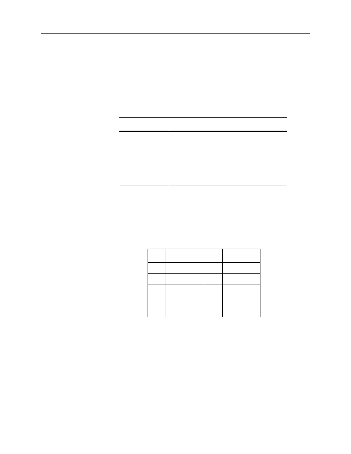
Editor Port Jumpers
Jumper settings on the Control Processor module must be set as follows for proper
operation of the EDITOR port:
Model 3000
For the Model 3000, the EDITOR port jumpers are located on the Control
Processor module (068906) between the M/E 2 Processor mezzanine board
(068916) and the Serial Communications mezzanine board (068918). See Figure 1-
1. Jumper J71 sets the communication standard (RS-232 or RS-422); Jumper J70 sets
the EDITOR port termination (IN or OUT).
Communication Standard
Editor Port Jumpers
For RS-422 , set the two jumpers of J71 to the
in Figure 1-1. This connects pins 1 and 3 together and pins 2 and 4 together.
For RS-232 , set the two jumpers of J71 to the
3 and 5 together and pins 4 and 6 together.
J71
IN
TERM
OUT
Figure 1-1. EDITOR Port Jumper Settings on Model 3000
J70
EDITOR
(shown set for RS422, terminated)
DIFF
RS232
M/E 2 Processor
Mezzanine Board
Serial Communication
Mezzanine Board
(068918)
DIFF
RS232
(068916)
position (RS-422) as shown
position. This connects pins
0350-11
Control
Processor
Module
(068906)
rear
edge
connector
Termination
Set the two jumpers of J70 to either the
terminated) position, depending on the requirements of your system.
If J71 is set for RS-232, Jumper J70 has no effect.
IN
(terminated) position or the
OUT
(not
1-3
Page 12
Section 1 Ð Introduction
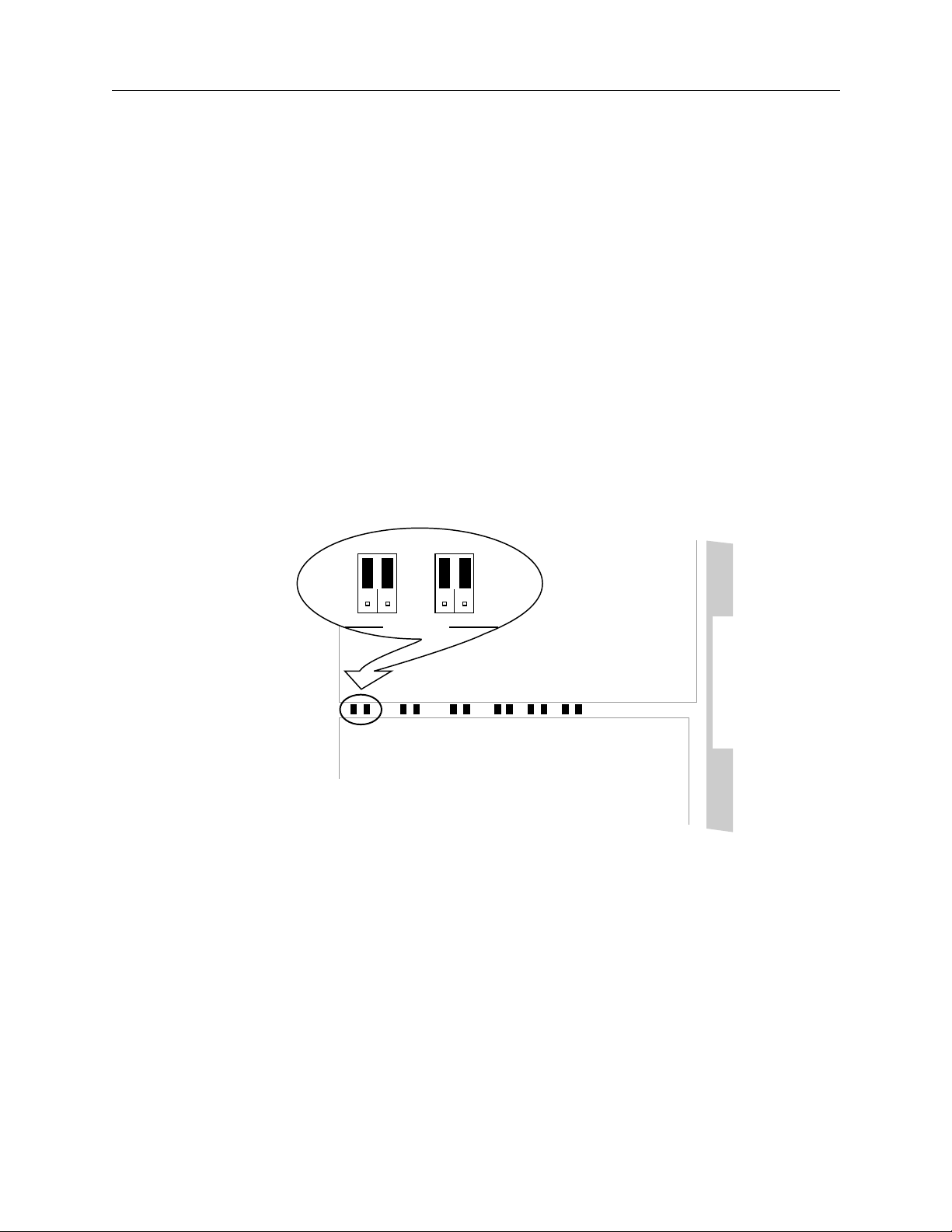
Model 2200/4000
For the Model 2200 or Model 4000, the EDITOR port jumpers are located on the
Control Processor II module (064806) as shown in Figure 1-2. Jumper J15 sets the
communication standard (RS-232 or RS-422); Jumpers J16, J17, and J18 set the
EDITOR port termination (terminated or not terminated).
1
J16
261
0350-12
J18
2
1
261
2
J15
5
EDITOR
RS422/RS232
SELECT
J17
5
6
SERIAL COMMUNICATION
TERMINATION SELECT
5
5
6
M/E 2 Processor
Mezzanine Board
(068916)
Figure 1-2. EDITOR Port Jumper Settings on Model 4000
(shown set for RS-422, terminated)
Communication Standard
For RS-422 , set the two jumpers of J15 to the upper (RS422) position as shown
in Figure 1-2. This connects pins 1 and 3 together and pins 2 and 4 together.
For RS-232 set the two jumpers of J15 to the lower (RS232) position. This
connects pins 3 and 5 together and pins 4 and 6 together.
Control
Processor II
Module
(064806)
rear
edge
connector
1-4
Termination
Set jumpers J16, J17, and J18 to either the upper (terminated) or lower (not
terminated) position, depending upon the requirements of your system. All
three of these jumpers should be set to the same position (all up or all down).
There is only one jumper for each of these jumper blocks.
If J15 is set for RS-232, Jumpers J16 through J18 have no effect.
Page 13
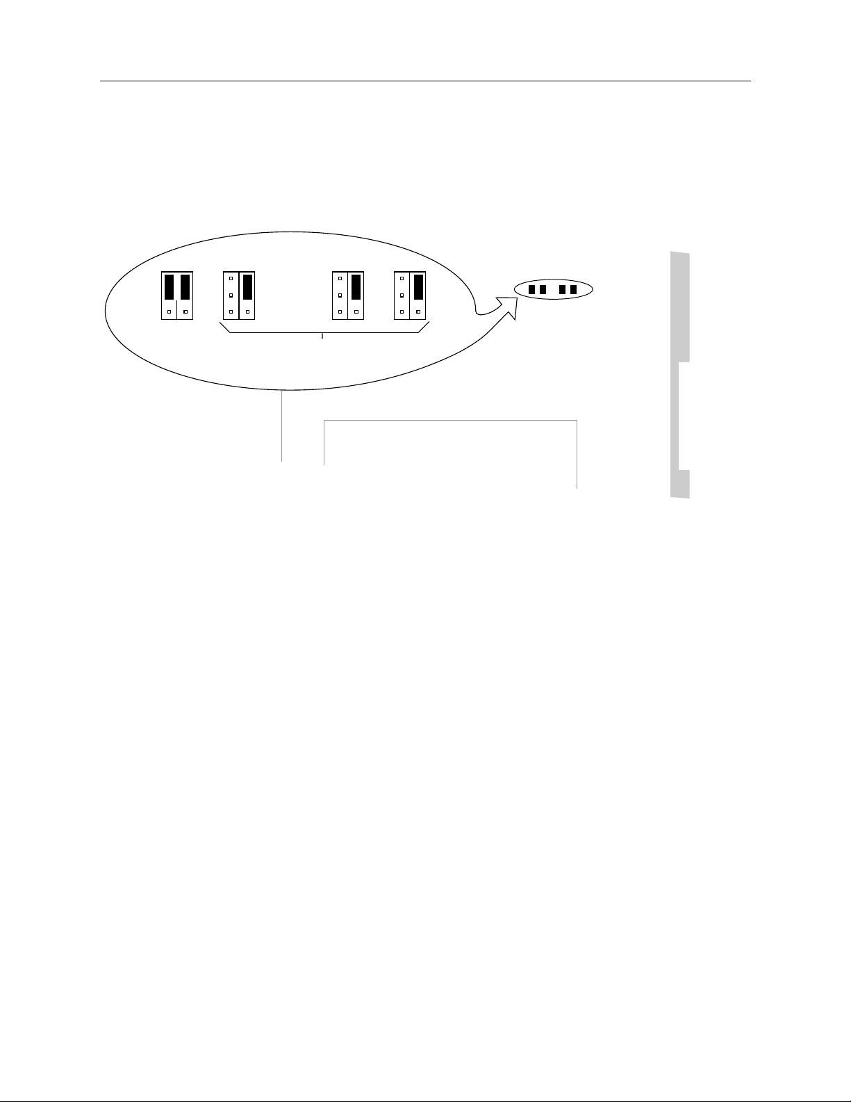
Serial Data Word Description
The serial data word contains eleven bits, as shown in Figure 1-3:
Serial Data Word Description
0350-02
D
1234
0
Data, 8 Bits, LSB First
Start Bit, Always Zero
Previous Character's Stop Bit
Stop Bit, Always One
Next Character's Start Bit
11 Bits Character Length
DD
Parity Bit
DD
567
D
PDD
Figure 1-3. Serial Data Word
1-5
Page 14

Section 1 Ð Introduction
Editor Enable Pushbutton
The
EDIT
pushbutton in the External Interface area of the Control Panel (Figure 1-
4) controls editor access to the switcher. When pressed, the pushbutton lights to
indicate that the switcher can be controlled through the Editor Interface. Pressing
EDIT
a second time turns the lamp off and disables editor control of the switcher.
When
EDIT
opposed to those requesting status information) are not forwarded to the switcher
as they arrive from the editor. This action by the switcher does not affect the editor,
which continues to send messages and function normally, even though it is being
ignored.
is turned off, protocol messages affecting switcher parameters (as
0350-10
EXTERNAL INTERFACE
DPMPERIPHGPIEDIT
System Performance
The Editor Interface can continuously receive and process a steady stream of
commands. Although all commands are received, some time may be required to
act upon these commands. For example, transferring E-MEM
the editor and the switcher may take several seconds to complete.
Any Read Command has a switcher latency of 2 Þelds; that is, the response will
occur 2 Þelds after the Read Command has been received.
All other commands except E-MEM and ConÞguration Transfer Commands have
a switcher latency of 10 Þelds.
E-MEM and ConÞguration Transfer Commands have no Þxed latency in the
switcher. The transfer will take place as soon as all higher-level commands have
been executed.
The transfer commands have a one second timeout imposed on the time between
each packet transmission.
Figure 1-4. External Interface Pushbuttons
¨
registers between
1-6
Page 15

2
Editor Protocol
Serial Communications
This section describes the communications protocol and its error handling.
A Video Editing System uses the switcher editor port to exercise real-time control
over the switcher's functions. The editor is really an external computer that can
input and output functions. Such functions select crosspoints, perform auto
transitions, or perform E-MEM (Effects Memory) register recalls, to name just a
few possibilities. Refer to the appropriate switcher Operation manual for
deÞnitions and explanations of the switcher functions and features.
Editor Protocol Access
The 2200/3000/4000 Editor Protocol is based upon, but not identical to, the
proposed SMPTE (Society of Motion Picture and Television Engineers) Digital
Control Interface, which establishes a means for the orderly ßow of data over a
serial bus.
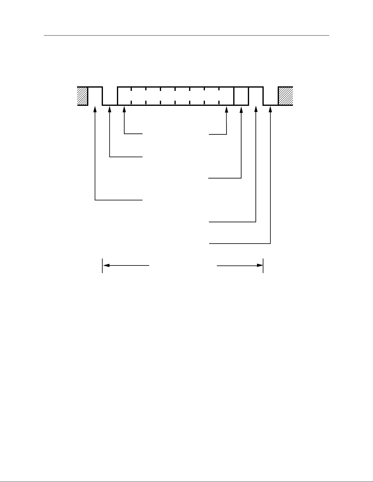
The major components of the protocol are shown in Figure 2-1 and discussed in
the following paragraphs.
Break
Character
Figure 2-1. Components of the Model 2200/3000/4000 Editor Protocol Access
Address
Byte
Command/Message Blocks
0350-06
2-1
Page 16

Section 2 Ð Editor Protocol
Break Character
The main component of the Editor Interface protocol is a 1-1/2 character-length
Òbreak.Ó A break consists of a spacing or logical low (0) condition on the serial bus
(see Figure 2-2) followed by a minimum of two bit-times of marking (logic 1)
condition. The Bus Controller (editor) transmits a break to the switcher,
forewarning of an impending message.
1 Bit Time (26µS @ 38.4K Baud)
0350-07
Spacing Data
17 to 20 Bit Times
Marking Data
2 or More Bit Times
First
Character
of Address
Byte
SMPTE Break Character
Figure 2-2. Break Character
The break forces all tributaries , or listeners (such as the switcherÕs editor port),
from the ÒIdleÓ state into the ÒActiveÓ state. A break can be sent only by the Edit
Controller. When the switcher receives the break, it ceases all bus
communications, resets any communication error condition, and prepares to
receive an address.
2-2
Page 17
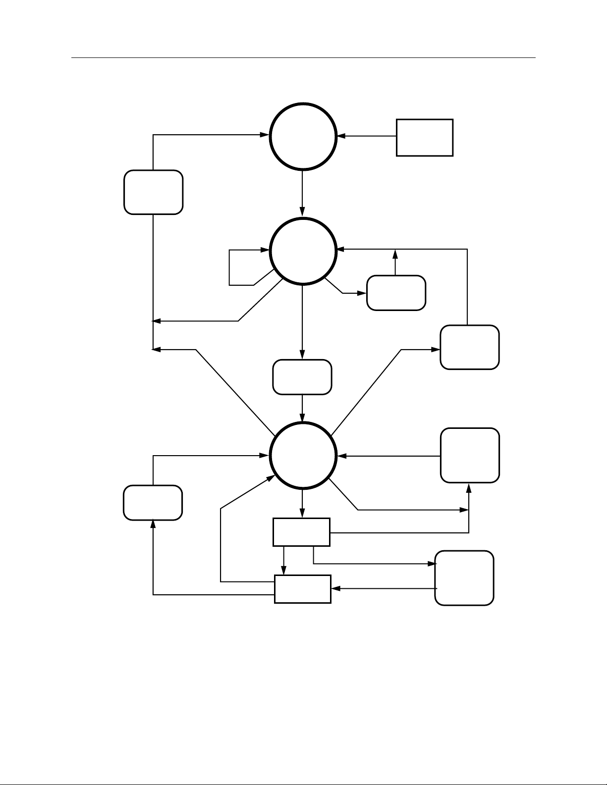
Idle
Editor Protocol Access
Power On
– or –
Reset
Transmit
Negative
‘Ack’ (85H)
Line Error
Invalid Address
Line Error
Transmit
Data Msg
– or –
Valid Break
– or –
Timeout
Valid Select
Address (30H)
“Write”
Msg
Valid
Break
Active
Transmit
‘Ack’ (84H)
Selected
Valid
Poll Address
(31H)
Transmit
‘Ack’ (84H)
Timeout
Valid
Break
Transmit
Negative
‘Ack’ (85H)
Transmit
Protocol
Error Msg
(01 40)
Validate
Fails
Msg Block
“Read” Msg
“Read”
Msg
Execute
Msg Block
“Write” Msg
Figure 2-3. Serial Interface Protocol State Diagram
Transmit
Protocol
Accept Msg
(01 80)
2-3
Page 18

Section 2 Ð Editor Protocol
Address Byte
Once the break has been received, the Editor Interface advances to the active state
and begins expecting a one-byte address. The switcher will respond to the
switcher address 30H (Hexadecimal), when transmitted by the Edit controller.
After receiving the address, the Editor Interface accepts command/message block
transmissions containing commands, data requests, and other data directed
toward the switcher. As long as communication errors do not occur, the Editor
Interface can skip the break/address sequence during the remainder of the
transmissions. Command/message blocks can be sent repeatedly, one after
another, without break interruptions.
The address is one byte long and directed to a speciÞc tributary. If the received
address matches the tributaryÕs assigned address, the tributary advances to the
Selected state and awaits instructions. The address of the switcher is Þxed as 30H.
In response to the address, the 3000 transmits an acknowledgment byte of 84H to
the controller, indicating the change in status to the ÒSelectedÓ State. If an address
of 31H is received, the switcher transmits an acknowledgment byte of 84H to the
controller, but stays in the ÒActiveÓ State. If the address does not match, the
tributary drops off the bus (goes Idle) and awaits another break.
Note that when the switcher receives a break without an address as a result of an
Editor Interface reset (
Interface), it returns the 84H acknowledgment byte to the controller. If the edit
controller sends subsequent breaks to the switcher (when no Editor Interface reset
has occurred), the switcher responds by sending 85H followed by 84H.
RESET
button pressed, or a warm or cold start of the Editor
2-4
Page 19
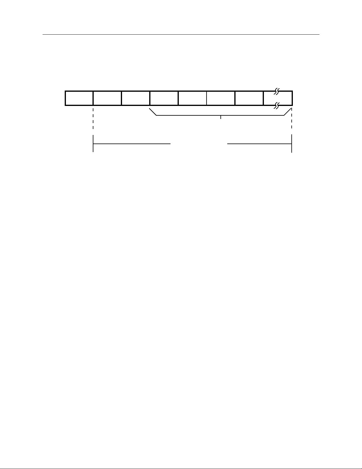
Command/Message Block Structure
In the Selected state, the Editor Interface receives command/message blocks that
direct switcher operations. The basic message structure is shown in Figure 2-4.
Command/Message Block Structure
0350-09
Byte Count
Byte
Byte Count
Effects
Addr. Byte
Command
Code Byte
Message Bytes
Maximum Size
255 Bytes
Figure 2-4. Message Structure
The maximum length of a message is 255 bytes plus the byte count byte. At a baud
rate of 38,400, the maximum length command/message takes more than 4 Þelds to
complete.
The Editor Interface can handle data continuously, receiving a contiguous stream
of command/message blocks. Such an ability enables multiple switcher
operations to be performed without constant cycling through the break/address
sequence. Responses (handshakes or read data) are returned in the same order as
the command/message blocks are received.
The command/message block can range in size from two to 256 bytes. The Þrst
byte of the block contains the byte count. A byte count consists of the total number
of subsequent bytes in the block; valid byte count values range from 01H to FFH
(1 to 255). After receiving a valid byte count (01H to FFH) and the proper number
of data bytes (1 to 255), the Model 3000 executes the command.
Effects Address Byte
The second byte of the command/message block is the effects address byte,
typically referred to as EX. This byte identiÞes the desired Òeffect bankÓ within the
switcher where the associated command will go. Valid Effects Addresses for each
command are speciÞed in Section 3.
2-5
Page 20

Section 2 Ð Editor Protocol
Command Code Byte
The command code is the third byte of the command/message block. Command
codes fall into two broad categories: read commands and write commands. Only
one command is allowed in any command/message block. Likewise, only one
response is embedded in any command/message block.
Read Commands
Read commands interrogate the status of the speciÞed operational parameter of
the switcher. When the editor issues a read command/message block, the
switcher responds by sending the current status of the requested operational
parameter(s) back to the editor. This status information is returned in the format of
the write command/message block. By echoing the write format, the editor can
later send responses to a read command to the switcher and cause execution of
that function.
Write Commands
Write commands are used by the editor to change operational parameter(s) or
initiate a function within the switcher.
2-6
Page 21

Status and Data Replies
The editor interface does not respond to the controlling device upon the receipt of
each and every character. It does respond to the last character of any complete
message. The Þrst character of any message is the Òbyte countÓ byte, specifying
the number of message bytes that are to follow. A message transmission is
complete when the total number of characters speciÞed by that byte plus that byte
itself have been received.
There are Þve possible replies in response to the complete message as outlined in
Table 2-1.
Response Type Message In Response To:
Acknowledge 0x84 Valid Select or Poll Address
Status and Data Replies
Table 2-1. Possible Command Responses
Negative
Acknowledge
Protocol Error 0x01 0x40 Invalid Protocol Message (Read or Write);
Command Accepted 0x01 0x80 Valid Protocol “Write” Message
Data Message Write Message
Once the interface is placed into the Select State, the most common response is one
of the two-byte status reply messages. The second byte of this message is the
response to the command. The upper two bits signify whether the command was
accepted or not as illustrated in the following Þgure:
Bit Bit
0x85 Invalid Select or Poll Address; Line Error
Timeout Error in Select State
Valid Protocol “Read” Message
(length varies)
7 6 5 4 3 2 1 0
X X 0 0 0 0 0 0
1 = Protocol Error
1 = Command Accepted
Note that these bits are mutually exclusive; that is, both may not be set in the same
message.
If Command Accept is true, the message was forwarded to its handler for
execution. However, this status reply only means that the command was received
with no transmission errors and passed the protocol validation test (byte count
and command code) for the message structure itself. The message may still not be
executed by the Switcher for failures on the Protocol Command level.
2-7
Page 22

Section 2 Ð Editor Protocol
Error Detection
Transmission Errors
Error detection is a normal part of the communication process. For this Protocol
Interface, error detection and reporting is limited to problems that occur at the
transmission and reception level of communication. These type of errors fall into
two basic categories, line and time-out errors.
Line errors include three speciÞc types of errors that may occur with each
character transmission and reception.
¥
¥
¥
These errors occur when the Serial Data Word becomes corrupted.
Parity error
Framing error
Data Overrun error
Time-out errors occur when too much time elapses between the reception of
characters during a message transmission.
When the Editor Interface detects communication errors, it responds with a
negative acknowledge of 85H and then aborts all communications. Any remaining
un-executed commands are discarded after the error indication occurs and the
Interface is forced back into the Idle state. Refer to Figure 2-2 on page 2-2 and Table
2-1 for details of the detection and corresponding response to each error type.
In order to resume communications, the Editor must transmit a break/address
sequence to return the channel to the Select state. If the Editor Interface does not
receive a valid tributary or poll address following the break, it falls back into the
Idle state without transmitting the 85H Negative Acknowledge byte. Line errors
that occur during an attempt to send and receive the address byte still result in a
Negative Acknowledge byte being sent back to the Editor.
2-8
Page 23

Protocol Errors
Errors can occur on the Protocol level itself; that is, the message may be received
okay, but may not actually be executed due to problems with content or context.
The only error that will be reported to the Editor as a Protocol Error (01 40) occurs
if either the byte count or the command code fail the validation test when a
complete message is received.
All other protocol errors go unreported back to the Editor. The only response the
Editor receives to these messages is a Command Accepted message. The handler,
when it uncovers a problem, will simply throw the message away and the user
will see no change to the operation of the Switcher.
Some possible causes of unreported protocol errors are listed as follows:
Content Errors:
¥
¥
Invalid effects address.
Invalid data (register number, analog value, etc.)
Error Detection
Context Errors:
¥
Command is Òpanel-centricÓ and may only be executed when the Switcher
is in a specific state.
2-9
Page 24

Section 2 Ð Editor Protocol
2-10
Page 25

3
Introduction
Editor Interface Commands
This section details the Switcher Editor Interface commands for Model 2200, 3000,
and 4000 Switchers.
References to pushbuttons are shown in capital letters, using the legends as they
appear on a Control Panel. Control Panel section names are shown in initial
capitals.
NOTE:
by the notation Òdecimal.Ó
All values within the tables are hexadecimal unless otherwise indicated
Editor Interface Commands
This section describes the traditional editor command set which bears a family
resemblance to earlier generation Grass Valley switchers such as the Model 200
and the Model 300.
Editor interface commands are detailed in tables presented on the following
pages. Addresses, byte counts, important names, and supporting details are listed
for each command.
With Software Version 5.1, new commands are added and some existing
commands enhanced. This is clearly marked for each command. Also, with
Version 5.1, Grass Valley has developed a new parameter-based command set
(PBCS) for advanced editing control. PBCS allows setting, trimming, and reading
of all internal switcher parameters completely independent of panel operations.
This is described in Section 4.
3-1
Page 26

Section 3 Ð Editor Interface Commands
The appropriate command to use may be determined as follows:
For basic crosspoint control use:
¥
Crosspoint Bus (C1) Command (PGM/BKGD A/AUX) on page 3-6
¥
Crosspoint Bus (C2) Command (PST/BKGD B) on page 3-8
¥
Crosspoint Bus (C3) Command (KEY 1/DSK 1) on page 3-9
¥
Crosspoint Bus (C4) Command (KEY 2/DSK 2) on page 3-10
¥
Crosspoint Bus (E2) Command (PVW) on page 3-11
¥
Crosspoint Bus (E3) Command (MASK) on page 3-12
¥
Write Split Key (E4) Command on page 3-38
Select Wipe Patterns by using:
¥ Write Wipe Pattern (C8) Command on page 3-21
Control the Transition mode pushbuttons by using:
¥ Write Transition Mode (CA) Command on page 3-23
Set transition rates by using:
¥ Write Auto Transition Rate (CC) Command on page 3-27
¥ Write Key Transition Rate (CD) Command on page 3-29
To simulate the pressing of buttons on the transition subpanel use:
¥ Pushbutton Select and Control (C6, C7 and FB) Commands on page 3-13
For E-MEM learns and recalls use:
¥ Write Learn E-MEM Register (DA) Command on page 3-35
¥ Write Recall E-MEM Register (DB) Command on page 3-31
For E-MEM and ConÞguration Data transfer use:
¥ Data Transfer (5E and DE) Commands on page 3-41
To control the timeline for multiple keyframe effects use:
¥ Timeline Control (4E, 4F, CE, and CF) Commands on page 3-52
To simulate pressing buttons on the timeline run control subpanel use:
¥ Pushbutton Select and Control (C6, C7 and FB) Commands on page 3-13
For general use by an editor, the following commands are provided:
¥ ALL STOP (F2) Command (Version 5.1 and Later) on page 3-5
¥ Software Version (6C and EC) Commands on page 3-50
¥ Select ÒLayeredÓ Or ÒStandardÓ (E8) Command on page 3-40
3-2
Page 27

Revision History
Revision History
The following commands were not supported prior to Version 5.1:
¥ ALL STOP (F2) Command (Version 5.1 and Later) on page 3-5
¥ Software Version (6C and EC) Commands on page 3-50
¥ Timeline Control (4E, 4F, CE, and CF) Commands on page 3-52
The following commands had functionality added for Version 5.1 that was not
supported in Version 5.0 and earlier:
¥ Pushbutton Select and Control (C6, C7 and FB) Commands on page 3-13
¥ Write Transition Mode (CA) Command on page 3-23
¥ Write Auto Transition Rate (CC) Command on page 3-27
¥ Write Key Transition Rate (CD) Command on page 3-29
¥ Write Recall E-MEM Register (DB) Command on page 3-31
¥ Write Learn E-MEM Register (DA) Command on page 3-35
¥ Data Transfer (5E and DE) Commands on page 3-41
The enhancements introduced in Version 5.1 to these commands are all additions;
functionality existing in Version 5.0 is still supported.
3-3
Page 28

Section 3 Ð Editor Interface Commands
Application Examples
Several examples of serial communications using the switcher Editor Interface are
provided on the following pages in the sections appropriate to the commands. In
general, ÒTransmitÓ refers to communication from the editor to the switcher and
ÒReceiveÓ refers to communication from the switcher to the editor. Refer to
speciÞc command tables for details on these examples.
Example 1: Bringing the Editor Interface into a Ready State
Transmit: Break Address
BRK 30
Receive: Status
84
Example 2: How to Set Crosspoint #6, A Row, Mix/Effects 2
Transmit: Byte Count Ex Address Command Data
03 02 C1 06
Receive: Byte Count Status
01 80
3-4
Page 29

ALL STOP (F2) Command (Version 5.1 and Later)
ALL STOP (F2) Command (Version 5.1 and Later)
The ALL STOP command is issued to set all or a speciÞc part of the switcher to a
known state. The command causes the following functions to occur:
1. An ongoing KEY 1 MIX or KEY 2 MIX is stopped.
2. An ongoing AUTO TRAN (Transition) is stopped.
3. An ongoing EFF DIS (Effects Dissolve) is stopped.
4. An ongoing SEQ (Sequence) is stopped.
5. The lever arm is set to a limit.
6. The transition type is set to MIX.
7. The transition mode is set to BKGD in Standard Mode and BKGD A in
Layered Mode.
8. For Standard mode, all Keys are removed. For Layered mode, all Keys
are left alone.
9. The crosspoint selections remain unchanged.
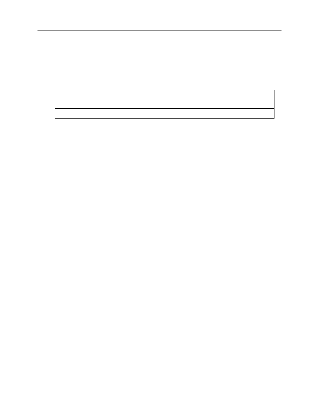
Table 3-1. All Stop Command
Function
Write 03 EX F2 FF
Byte
Count
Effects
Address
Command
Code
Message
Effects Addresses
Valid effects addresses for the ALL STOP command are as follows:
EFFECTS ADDRESS ASSIGNMENTS
00 PGM-PST Mix System
01 Mix/Effects 1 System
02 Mix/Effects 2 System
03 Mix/Effects 3 System
04 Downstream Keyer (DSK)
05 Background (BKGD)
06 Miscellaneous (MISC)
07 DPM 1
08 DPM 2
09 DPM 3
0A DPM 4
0B All levels
3-5
Page 30
Section 3 Ð Editor Interface Commands
Crosspoint Bus (C1) Command (PGM/BKGD A/AUX)
The Write Crosspoint Bus command enables the editor to select any crosspoint on
a bus speciÞed by the effects address, and the command code.
Table 3-2. Crosspoint Bus Command
Function
Write Crosspoint Bus 03 EX C1 (Write) Crosspoint #
Byte
Count
Effects
Address
Command
Code
Message
Effects Addresses
Valid effects addresses for the Crosspoint Bus command are as follows:
EFFECTS ADDRESS ASSIGNMENTS
00 PGM-PST System (PGM)
01 Mix/Effects 1 (BKGD A)
02 Mix/Effects 2 (BKGD A)
03 Mix/Effects 3 (BKGD A)
0C Aux Bus 1A
0D Aux Bus 1B
0E Aux Bus 2A
0F Aux Bus 2B
10 Aux Bus 3A
11 Aux Bus 3B
12 Aux Bus 4A
13 Aux Bus 4B
14 Aux Bus 5A
15 Aux Bus 5B
16 Aux Bus 6A
17 Aux Bus 6B
18 Aux Bus 7A
19 Aux Bus 7B
1A Aux Bus 8A
1B Aux Bus 8B
1C Aux Bus 9A
1D Aux Bus 9B
3-6
Page 31

Crosspoint Bus (C1) Command (PGM/BKGD A/AUX)
Crosspoint Numbers
Valid crosspoint numbers are as follows:
Table 3-3. Common Crosspoint Numbers for All Buses
Crosspoint Name Number Crosspoint Name Number
Crosspoint 1 01H Crosspoint 29 1DH
Crosspoint 2 02H Crosspoint 30 1EH
Crosspoint 3 03H Crosspoint 31 1FH
Crosspoint 4 04H Crosspoint 32 20H
Crosspoint 5 05H Crosspoint 33 21H
Crosspoint 6 06H Crosspoint 34 22H
Crosspoint 7 07H Crosspoint 35 23H
Crosspoint 8 08H Crosspoint 36 24H
Crosspoint 9 09H Crosspoint 37 25H
Crosspoint 10 0AH Crosspoint 38 26H
Crosspoint 11 0BH Crosspoint 39 27H
Crosspoint 12 0CH Crosspoint 40 28H
Crosspoint 13 0DH Crosspoint 41 29H
Crosspoint 14 0EH Crosspoint 42 2AH
Crosspoint 15 0FH Crosspoint 43 2BH
Crosspoint 16 10H Crosspoint 44 2CH
Crosspoint 17 11H Crosspoint 45 2DH
Crosspoint 18 12H Crosspoint 46 2EH
Crosspoint 19 13H Crosspoint 47 2FH
Crosspoint 20 14H Crosspoint 48 30H
Crosspoint 21 15H M/E 1 31H
Crosspoint 22 16H M/E 2 32H
Crosspoint 23 17H M/E 3 33H
Crosspoint 24 18H PGM Out 34H (1)
Crosspoint 25 19H M/E 1 PVW 35H (2)
Crosspoint 26 1AH M/E 2 PVW 36H (2)
Crosspoint 27 1BH M/E 3 PVW 37H (2)
Crosspoint 28 1CH DSK PVW 38H (2)
(1) Accessible only on AUX buses, PVW bus, and MASK bus
(2) Accessible only on PVW bus
3-7
Page 32

Section 3 Ð Editor Interface Commands
Crosspoint Bus (C2) Command (PST/BKGD B)
The Write Crosspoint Bus command enables the editor to select any crosspoint on
a bus speciÞed by the effects address, and the command code.
Table 3-4. Crosspoint Bus Command
Function
Write Crosspoint Bus 03 EX C2 (Write) Crosspoint #
Byte
Count
Effects
Address
Command
Code
Message
Effects Addresses
Valid effects addresses for the Crosspoint Bus command are as follows:
EFFECTS ADDRESS ASSIGNMENTS
00 PGM-PST Mix System (PST)
01 Mix/Effects 1 (BKGD B)
02 Mix/Effects 2 (BKGD B)
03 Mix/Effects 3 (BKGD B)
Crosspoint Numbers
Valid crosspoint numbers are shown in Table 3-3, ÒCommon Crosspoint Numbers
for All Buses,Ó on page 3-7.
3-8
Page 33

Crosspoint Bus (C3) Command (KEY 1/DSK 1)
Crosspoint Bus (C3) Command (KEY 1/DSK 1)
The Write Crosspoint Bus command enables the editor to select any crosspoint on
a bus speciÞed by the effects address, and the command code.
Table 3-5. Crosspoint Bus Command
Function
Write Crosspoint Bus 03 EX C3 (Write) Crosspoint #
Byte
Count
Effects
Address
Command
Code
Message
Effects Addresses
Valid effects addresses for the Crosspoint Bus command are as follows:
EFFECTS ADDRESS ASSIGNMENTS
01 Mix/Effects 1 (KEY 1)
02 Mix/Effects 2 (KEY 1)
03 Mix/Effects 3 (KEY 1)
04 DSK 1
Crosspoint Numbers
Valid crosspoint numbers are shown in Table 3-3, ÒCommon Crosspoint Numbers
for All Buses,Ó on page 3-7.
3-9
Page 34

Section 3 Ð Editor Interface Commands
Crosspoint Bus (C4) Command (KEY 2/DSK 2)
The Write Crosspoint Bus command enables the editor to select any crosspoint on
a bus speciÞed by the effects address, and the command code.
Table 3-6. Crosspoint Bus Command
Function
Write Crosspoint Bus 03 EX C4 (Write) Crosspoint #
Byte
Count
Effects
Address
Command
Code
Message
Effects Addresses
Valid effects addresses for the Crosspoint Bus command are as follows:
EFFECTS ADDRESS ASSIGNMENTS
01 Mix/Effects 1 (KEY 2)
02 Mix/Effects 2 (KEY 2)
03 Mix/Effects 3 (KEY 2)
04 DSK 2
Crosspoint Numbers
Valid crosspoint numbers are shown in Table 3-3, ÒCommon Crosspoint Numbers
for All Buses,Ó on page 3-7.
3-10
Page 35

Crosspoint Bus (E2) Command (PVW)
The Write Crosspoint Bus command enables the editor to select any crosspoint on
a bus speciÞed by the effects address.
Table 3-7. Crosspoint Bus Command
Crosspoint Bus (E2) Command (PVW)
Function
Write Crosspoint Bus 03 EX E2 (Write) Crosspoint #
Byte
Count
Effects
Address
Command
Code
Message
Effects Addresses
Valid effects addresses for the Crosspoint Bus command are as follows:
EFFECTS ADDRESS ASSIGNMENTS
06 PVW Bus (MISC)
Crosspoint Numbers
Valid crosspoint numbers are shown in Table 3-3, ÒCommon Crosspoint Numbers
for All Buses,Ó on page 3-7.
3-11
Page 36

Section 3 Ð Editor Interface Commands
Crosspoint Bus (E3) Command (MASK)
The Write Crosspoint Bus command enables the editor to select any crosspoint on
a bus speciÞed by the effects address.
Table 3-8. Crosspoint Bus Command
Function
Write Crosspoint Bus 03 EX E3 (Write) Crosspoint #
Byte
Count
Effects
Address
Command
Code
Message
Effects Addresses
Valid effects addresses for the Crosspoint Bus command are as follows:
EFFECTS ADDRESS ASSIGNMENTS
06 MASK Bus (MISC)
Crosspoint Numbers
Valid crosspoint numbers are shown in Table 3-3, ÒCommon Crosspoint Numbers
for All Buses,Ó on page 3-7.
3-12
Page 37

Pushbutton Select and Control (C6, C7 and FB) Commands
Pushbutton Select and Control (C6, C7 and FB) Commands
The Pushbutton Select command (FB) is a write-only command that performs a
ÒpushÓ of the speciÞed pushbutton number, just as if the button had actually been
pressed at the control panel.
The Pushbutton Write commands turn the designated pushbutton either ÒonÓ
(C6) or ÒoffÓ (C7).
Table 3-9. Pushbutton Select and Control Commands
Function
Write PB/L# ON 04 EX C6 (Write
Write PB/L# OFF 04 EX C7 (Write
Select PB/L# 04 EX FB (Write) PB/L# High, PB/L# Low
Byte
Count
Effects
Address
Command
Code
on)
off)
Message
PB/L# High, PB/L# Low
PB/L# High, PB/L# Low
Effects Addresses
Valid effects addresses for the Pushbutton Control commands are:
EFFECTS ADDRESS ASSIGNMENTS
00 PGM-PST Mix System
01 Mix/Effects 1 System
02 Mix/Effects 2 System
03 Mix/Effects 3 System
04 Downstream Keyer (DSK)
05 Background (BKGD)
06 Miscellaneous (MISC)
0B Master E-MEM
3-13
Page 38

Section 3 Ð Editor Interface Commands
Pushbutton Numbers
The pushbutton numbers supported by these commands cover the transition
subpanels and the timeline run control subpanel. These numbers are speciÞed in
Table 3-10, ÒTransition Subpanel Pushbutton Numbers,Ó on page 3-15 and Table 311, ÒKeyframing Pushbutton Numbers,Ó on page 3-16.
The original intent of the switcher design team was to extend the range of these
commands to cover the pressing of all buttons on the control panel. However, over
time, it became clear that a better serial interface to provide for editors is the
parameter-based command set (PBCS). This new command set directly sets the
internal switcher state irrespective of whatever control panel may, or may not, be
attached. So, for backward compatibility, a further set of pushbutton numbers is
supplied for the wipe subpanel in Table 3-12, ÒObsolete Pushbutton Numbers Ð,Ó
on page 3-17. Although these commands do work, it is recommended that wipes
be set by using the Write Wipe Pattern (C8) Command on page 3-21 or the PBCS
described in Section 4.
WARNING
Specifying an invalid pushbutton number may produce an
unpredictable result.
Also, please note that on the M/E Transition Panel (and DSK for 4000-2A):
¥ MIX and WIPE are mutually exclusive. Turning on one turns off the other.
3-14
Page 39

Pushbutton Select and Control (C6, C7 and FB) Commands
Table 3-10. Transition Subpanel Pushbutton Numbers
Pushbutton#
0201H X CUT X X
0202H X AUTO TRAN X X
0203H X X PST BLK X X
0206H X X (3) MIX X (2) X
0207H X BKGD X
0208H X X (3) WIPE X (2) X
0209H X DSK 1 X
020AH X BKGD A X
020BH X DSK 2 X
020CH X BKGD B X
020DH X DSK 1 ON X
020EH X KEY 1 X
020FH X DSK 2 ON X
0210H X KEY 2 X
Select
(Press)
Write
(On/Off)
Pushbutton Function
PGM/
DSK
M/E
Master
E-MEM
0212H X X KEY PRI X
0214H X BKGD A ON X
0216H X BKGD B ON X
0218H X TRANS KEY 1 ON X
021AH X TRANS KEY 2 ON X
0222H X LAYERED X
0223H X (1) X (1) KEY 1 CUT (DSK 1 CUT) X X
0224H X (1) KEY 1 MIX (DSK 1 MIX) X X
0225H X (1) X (1) KEY 2 CUT (DSK 2 CUT) X X
0226H X (1) KEY 2 MIX (DSK 2 MIX) X X
(1) Not supported in Version 5.0 and earlier.
(2) Model 4000-2A only.
(3) Write On only.
3-15
Page 40

Section 3 Ð Editor Interface Commands
Table 3-11. Keyframing Pushbutton Numbers
Pushbutton#
0501H X (1) X (1) ENABLE PGM PST X (2)
0502H X (1) X (1) ENABLE M/E 1 X (2)
0503H X (1) X (1) ENABLE M/E 2 X (2)
0504H X (1) X (1) ENABLE M/E 3 X (2)
0505H X (1) X (1) ENABLE DSK X (2)
0506H X (1) X (1) ENABLE BKGD X (2)
0507H X (1) X (1) ENABLE MISC X (2)
0508H X (1) X (1) ENABLE DPM 1 X (2)
0509H X (1) X (1) ENABLE DPM 2 X (2)
050AH X (1) X (1) ENABLE DPM 3 X (2)
050BH X (1) X (1) ENABLE DPM 4 X (2)
050CH X (1) X (1) ENABLE ALL X (2)
0544H X PREV X (2)
0545H X NEXT X (2)
Select
(Press)
Write
(On/Off)
Pushbutton Function
PGM/
DSK
M/E
Master
E-MEM
0560H X REWIND X (2)
0561H X X (1) HOLD INPUT X (2)
0562H X X (1) REV X (2)
0563H X X (1) AUTO RUN X (2)
0564H X X (1) STOP NEXT KF X (2)
0565H X RUN X (2)
0580H X X (1) AUTO RCL X (2)
(1) Not supported in Version 5.0 and earlier.
(2) Effects addresses are irrelevant and will be ignored. All effects addresses will be treated as 0X0B.
3-16
Page 41

Pushbutton Select and Control (C6, C7 and FB) Commands
Table 3-12. Obsolete Pushbutton Numbers Ð (Sheet 1 of 4)
Pushbutton/
Lamp#
1601H X WIPE SOFT – PRI X X
1602H X WIPE BORD – PRI X X
1603H X WIPE ASPECT – PRI X X
1604H X WIPE ROT POS – PRI X X
1605H X WIPE ROT SPD – PRI X X
1606H X WIPE ROT MAG – PRI X X
1607H X WIPE DIR N ORM – PRI X X
1608H X WIPE DIR REV – PRI X X
1609H X WIPE DIR FLIP – PRI X X
160AH X WIPE SPLIT – PRI X X
160BH X WIPE H MULTI – PRI X X
160CH X WIPE V MULTI – PRI X X
160DH X WIPE POS NORM – PRI X X
160EH X WIPE POS AUTO – PRI X X
Select
(Press)
Write
(On/Off)
Pushbutton
PGM/
DSK
M/E
Master
E-MEM
160FH X WIPE PATT MIX – PRI X X
1610H X WIPE M/E 1 PRI X X
1611H X WIPE M/E 2 PRI X X
1612H X WIPE M/E 3 PRI X X
1613H X WIPE M/E 1 SEC X X
1614H X WIPE M/E 2 SEC X X
1615H X WIPE M/E 3 SECI X X
1616H X WIPE PGM PRI X X
1617H X WIPE PGM SEC X X
1618H X WIPE PATT 0 – PRI X X
1619H X WIPE PATT 1 – PRI X X
161AH X WIPE PATT 2 – PRI X X
161BH X WIPE PATT 3 – PRI X X
161CH X WIPE PATT 4 – PRI X X
161DH X WIPE PATT 5 – PRI X X
161EH X WIPE PATT 6 – PRI X X
161FH X WIPE PATT 7 – PRI X X
3-17
Page 42

Section 3 Ð Editor Interface Commands
Table 3-12. Obsolete Pushbutton Numbers (Continued) Ð (Sheet 2 of 4)
Pushbutton/
Lamp#
1620H X WIPE PATT 8 – PRI X X
1621H X WIPE PATT 9 – PRI X X
1622H X WIPE PATT 10 – PRI X X
1623H X WIPE PATT 11 – PRI X X
1624H X WIPE PATT 12 – PRI X X
1625H X WIPE PATT 13 – PRI X X
1626H X WIPE PATT 14 – PRI X X
1627H X WIPE PATT 15 – PRI X X
1628H X WIPE PATT 16 – PRI X X
1629H X WIPE PATT 17 – PRI X X
162AH X WIPE PATT 18 – PRI X X
162BH X WIPE PATT 19 – PRI X X
162CH X WIPE PATT 20 – PRI X X
162DH X WIPE MENU – PRI X X
Select
(Press)
Write
(On/Off)
Pushbutton
PGM/
DSK
M/E
Master
E-MEM
162EH X WIPE RANDOM – PRI X X
162FH X WIPE TEXTURE – PRI X X
1630H X WIPE UW UNDO – PRI X X
1631H X WIPE UW LEARN – PRI X X
1632H X WIPE USER 1 – PRI X X
1633H X WIPE USER 2 – PRI X X
1634H X WIPE USER 3 – PRI X X
1635H X WIPE USER 4 – PRI X X
1636H X WIPE USER 5 – PRI X X
1637H X WIPE USER 6 – PRI X X
1681H X WIPE SOFT – SEC X X
1682H X WIPE BORD – SEC X X
1683H X WIPE ASPECT – SEC X X
1684H X WIPE ROT POS – SEC X X
1685H X WIPE ROT SPD – SEC X X
1686H X WIPE ROT MAG – SEC X X
3-18
1687H X WIPE DIR NORM – SEC X X
Page 43

Pushbutton Select and Control (C6, C7 and FB) Commands
Table 3-12. Obsolete Pushbutton Numbers (Continued) Ð (Sheet 3 of 4)
Pushbutton/
Lamp#
1688H X WIPE DIR REV – SEC X X
1689H X WIPE DIR FLIP – SEC X X
168AH X WIPE SPLIT – SEC X X
168BH X WIPE H MULTI – SEC X X
168CH X WIPE V MULTI – SEC X X
168DH X WIPE POS NORM – SEC X X
168EH X WIPE POS AUTO – SEC X X
168FH X WIPE PATT MIX – SEC X X
1696H X WIPE PATT 0 – SEC X X
1697H X WIPE PATT 1 – SEC X X
1698H X WIPE PATT 2 – SEC X X
1699H X WIPE PATT 3 – SEC X X
169AH X WIPE PATT 4 – SEC X X
169BH X WIPE PATT 5 – SEC X X
Select
(Press)
Write
(On/Off)
Pushbutton
PGM/
DSK
M/E
Master
E-MEM
169CH X WIPE PATT 6 – SEC X X
169DH X WIPE PATT 7 – SEC X X
169EH X WIPE PATT 8 – SEC X X
169FH X WIPE PATT 9 – SEC X X
16A0H X WIPE PATT 10 – SEC X X
16A1H X WIPE PATT 11 – SEC X X
16A2H X WIPE PATT 12 – SEC X X
16A3H X WIPE PATT 13 – SEC X X
16A4H X WIPE PATT 14 – SEC X X
16A5H X WIPE PATT 15 – SEC X X
16A6H X WIPE PATT 16 – SEC X X
16A7H X WIPE PATT 17 – SEC X X
16A8H X WIPE PATT 18 – SEC X X
16A9H X WIPE PATT 19 – SEC X X
16AAH X WIPE PATT 20 – SEC X X
16ABH X WIPE MENU – SEC X X
16ACH X WIPE RANDOM – SEC X X
3-19
Page 44

Section 3 Ð Editor Interface Commands
Table 3-12. Obsolete Pushbutton Numbers (Continued) Ð (Sheet 4 of 4)
Pushbutton/
Lamp#
16ADH X WIPE TEXTURE – SEC X X
16AEH X WIPE UW UNDO – SEC X X
16AFH X WIPE UW LEARN – SEC X X
16B0H X WIPE USER 1 – SEC X X
16B1H X WIPE USER 2 – SEC X X
16B2H X WIPE USER 3 – SEC X X
16B3H X WIPE USER 4 – SEC X X
16B4H X WIPE USER 5 – SEC X X
16B5H X WIPE USER 6 – SEC X X
16C0H X WIPE POS CENTER X X
Select
(Press)
Write
(On/Off)
Pushbutton
PGM/
DSK
M/E
Master
E-MEM
3-20
Page 45

Write Wipe Pattern (C8) Command
The Write Wipe Pattern command selects the speciÞed primary or secondary wipe
pattern for an M/E. Only one primary and one secondary wipe pattern can be
active at a time for each M/E.
Table 3-13. Write Wipe Pattern Command
Write Wipe Pattern (C8) Command
Function
Write Wipe Pattern 03 EX C8 (Write) Wipe #
Byte
Count
Effects
Address
Command
Code
Message
Effects Addresses
Valid effects addresses for the Write Wipe Pattern command are:
EFFECTS ADDRESS ASSIGNMENTS
01 Mix/Effects 1 System
02 Mix/Effects 2 System
03 Mix/Effects 3 System
Wipe Numbers
Wipe numbers range from 00H to 41H, corresponding to decimal numbers 0
through 65 on the Wipe subpanel. Specifying an invalid wipe number can produce
unexpected results.
The format of the Wipe Number byte is as follows:
Bit Bit
7 6 5 4 3 2 1 0
P/S W W W W W W W
The seven least signiÞcant bits (W W W W W W W) represent the wipe number in
hexadecimal.
When the P/S bit is a 0, the editor selects a Primary Wipe Pattern; however, when
the P/S bit is a 1, the editor selects a Secondary Wipe Pattern.
Please note that Wipe Pattern number 59, ÒExternal,Ó can be used only with a
Secondary Wipe Pattern selection.
3-21
Page 46

Section 3 Ð Editor Interface Commands
Table 3-14. Wipe Pattern Names and Hexadecimal Numbers
Wipe Pattern Name
0 VERTICAL 00H 33 DIAMOND 21H
1 T/L CORNER 01H 34 DUAL DIAGONAL 22H
2 POINT DN 02H 35 DOUBLE H SAWT OOTH 23H
3 CIRCLE 03H 36 DOUBLE V SA WTOOTH 24H
4 DIAG LT 04H 37 4 X 3 RECTANGLE 25H
5 TRIANGLE 05H 38 SMALL RANDOM 26H
6 CLOCK 06H 39 LARGER RANDOM 27H
7 ARROW 07H 40 3 PT STAR 28H
8 HEXAGON 08H 41 4 PT STAR 29H
9 SPIRAL 09H 42 6 PT STAR – Small 2AH
10 HORIZONTAL 0AH 43 6 PT STAR – Large 2BH
11 T/R CORNER 0BH 44 8 PT STAR 2CH
12 POINT RT 0CH 45 TEXTURE 2DH
13 ELLIPSE 0DH 46 SLITSCAN 2EH
14 DIAG RT 0EH 47 V ZIG ZAG 2FH
Hexadecimal
Number
Wipe Pattern Name
Hexadecimal
Number
15 PENTAGON 0FH 48 V SCAN 30H
16 DUAL CLOCK 10H 49 H X-CROSS 31H
17 DIAGONAL CROSS 11H 50 V X-CROSS 32H
18 OCTAGON 12H 51 V SNOWFALL 33H
19 H ZIG ZAF 13H 52 H SNOWFALL 34H
20 V SPLIT 14H 53 V QUAD SPIRAL 35H
21 B/R CORNER 15H 54 DIAG ZIG ZAG 36H
22 POINT LT 16H 55 H QUAD SPIRAL 37H
23 SQUARE 17H 56 T/B ZIG ZAG 38H
24 CROSS 18H 57 L/R ZIG ZAG 39H
25 V SAWTOOTH 19H 58 CHECKERBOARD 3AH
26 H SAWTOOTH 1AH 59 EXTERNAL 3BH
27 5 PT STAR 1BH 60 USER 1 3CH
28 HEART 1CH 61 USER 2 3DH
29 H SCAN 1DH 62 USER 3 3EH
30 H SPLIT 1EH 63 USER 4 3FH
31 B/L CORNER 1FH 64 USER 5 40H
3-22
32 POINT UP 20H 65 USER 6 41H
Page 47

Write Transition Mode (CA) Command
The Write Transition Mode command sets up the Ònext transitionÓ that will occur
when any transition for that level is expected (via panel or editor command) is
sent.
Table 3-15. Write Transition Mode Command
Write Transition Mode (CA) Command
Function
Write Transition Mode 03 EX CA (Write) Mode
Byte
Count
Effects
Address
Command
Code
Message
Effects Addresses
Valid effects addresses for the Write Transition Mode command are:
EFFECTS ADDRESS ASSIGNMENTS
00 PGM-PST Mix System
01 Mix/Effects 1 System
02 Mix/Effects 2 System
03 Mix/Effects 3 System
04 Downstream Keyer (DSK)
For this command, writing to the PGM-PST or the DSK has exactly the same effect.
Mode Byte
The format of the Write Transition Mode byte is as follows for an M/E:
Bit Bit
7 6 5 4 3 2 1 0
0 0 0 X X X X X
1 = KEY 2 on
1 = KEY 1 on
1 = BKGD A on
1 = BKGD B on in layered mode
1 = Key Priority On
3-23
Page 48

Section 3 Ð Editor Interface Commands
For PGM-PST/DSK the format of the Write Transition Mode byte is as follows:
Bit Bit
7 6 5 4 3 2 1 0
0 0 0 X X X X X
After BKGD is set to ON, the next transition will occur on the PGM-PST bus.
1 = DSK 2 on
1 = DSK 1 on
1 = BKGD on (or PGM on for 4000-2A)
1 = PST on for 4000-2A in layered mode
1 = Key Priority On
NOTE:
Do not issue this command more than once per video field. If you do, the
last command sent will be the one executed.
3-24
Page 49

Write Transition Rate Commands
The Write Transition Rate commands set the rates used by the switcher to perform
a transition. They can also cause a transition to take place by setting the Òexecute
bit.Ó The Ònext transitionÓ which will occur should have been previously selected,
either manually at the panel or by sending a Write Transition Mode command.
Three transition rates may be set in the switcher:
¥ Auto transition rate
¥ Key 1 transition rate
¥ Key 2 transition rate
Which rate is used depends on:
¥ The switcher model
¥ The Ònext transitionÓ which has been selected
¥ The effects address
Model 3000-2 and 4000-2B
Write Transition Rate Commands
M/E1, M/E2, M/E3
The auto transition rate is always used.
PGM-PST/DSK
The transition rate depends on the state of the Ònext transition.Ó If the next
transition is set only to BKGD, then the auto transition rate is used. If the next
transition is set to DSK 1, DSK 2, or both, then the Key 1 transition rate is used. If
BKGD and KEY 1 or KEY 2 is selected, then the BKGD (PGM-PST) transition has
precedence over the DSK transition and the auto transition rate is used.
Model 2200-2
The auto transition rate is always used.
3-25
Page 50

Section 3 Ð Editor Interface Commands
Model 3000-3 and 4000-2A
M/E1, M/E2, (and M/E3 on 3000-3)
The transition rate depends on the state of the Ònext transition.Ó If the next
transition is set only to BKGD A (or BKGD B on a 4000-2A in layered mode), then
the auto transition rate is used. If the next transition is set to KEY 1, then the Key 1
transition rate is used. If the next transition is set to KEY 2, then the Key 2
transition rate is used. If a combination of BKGD, KEY 1 and KEY 2 is selected,
then the order of precedence is BKGD (auto transition rate), KEY 1 (Key 1 rate),
KEY 2 (Key 2 rate).
PGM-PST/DSK
Setting the transition rate is very similar to that for an M/E. If the next transition
is set only to PGM (or PST on a 4000-2A in layered mode), then the auto transition
rate is used. If the next transition is set to DSK 1, then the Key 1 transition rate is
used. If the next transition is set to DSK 2, then the Key 2 transition rate is used. If
a combination of PGM-PST, DSK 1 and DSK is selected, then the order of
precedence is PGM-PST (auto transition rate), DSK 1 (Key 1 rate), DSK 2 (Key 2
rate).
NOTE:
4000-2B and 2200-2 in that Key 1 and Key 2 transition rates may be set. If the
editor does not want to distinguish between Models, then it would be effective to
always set the Key 1 and Key 2 rates in a Write Auto Transition Rate command.
Transition Rates
Transition rates are speciÞed in numbers of frames.
To translate a transition rate in seconds to number of frames, use the following
formulae:
For NTSC:
Frame Rate = (transition time in seconds) x (30 frames/second)
For PAL:
Frame Rate = (transition time in seconds) x (25 frames/second)
As an example, take the case of a four (4) second AUTO TRAN. In such a case, the
frame rate (NTSC) is 120 frames (4 seconds * 30 frames/second = 120 frames). For
the PAL standard, substitute 25 frames, giving 100 frames.
The 4000-2A and the 3000-3 have more functionality than the 3000-2,
3-26
Page 51

Write Auto Transition Rate (CC) Command
Write Auto Transition Rate (CC) Command
The Write Auto Transition Rate command is primarily intended to set the auto
transition rate but can also set the Key 1 and Key 2 transition rates. If the execute
bit is set, the auto transition will be performed.
Table 3-16. Write Auto Transition Rate Command
Function
Write Auto Transition Rate 05 EX CC (Write) HD TN UN
Byte
Count
Effects
Address
Command
Code
Message
Effects Addresses
Valid effects addresses for the Write Auto Transition Rate commands are:
EFFECTS ADDRESS ASSIGNMENTS
00 PGM-PST Mix System
01 Mix/Effects 1 System
02 Mix/Effects 2 System
03 Mix/Effects 3 System
04 Downstream Keyer (DSK)
Writing to Effects Addresses 00 (PGM-PST) and 04 (DSK) have the same effect;
either can be used for this command.
2
1
Transition Rate
The command speciÞes the auto transition rate in terms of frames, ranging from
000 to 999. Specify the auto transition rate in the command by supplying three
data bytes:
¥ HD Ñ The hundreds digit in BCD. The MSB is the ÒexecuteÓ bit.
¥ TN Ñ The tens digit in BCD.
¥ UN Ñ The units digit in BCD. The two MSBs are control bits to select Key
1 and Key 2 rates in addition to the auto transition rate.
1. Not supported in Version 5.0 and earlier
2. For Version 5.0 and earlier, writing to address 04 (DSK) was not supported
3. For Version 5.0 and earlier, using the two MSBs to control KEY 1 and KEY 2 rates was not supported.
3
3-27
Page 52

Section 3 Ð Editor Interface Commands
The format of the HD byte is as follows:
Bit Bit
7 6 5 4 3 2 1 0
X 0 0 0 X X X X
The format of the TN byte is as follows:
Bit Bit
7 6 5 4 3 2 1 0
0 0 0 0 X X X X
Rate value of 0 through 9 in BCD (0000 to 1001)
do not
0 = Set rate only,
1 = Set rate and perform the auto transition.
Rate value of 0 through 9 in BCD (0000 to 1001)
perform the transition.
The format of the UN byte is as follows:
Bit Bit
7 6 5 4 3 2 1 0
X X 0 0 X X X X
Rate value of 0 through 9 in BCD (0000 to 1001)
1 = Set Key 1 rate also (1)
1 = Set Key 2 rate also (1)
(1) Not supported in Version 5.0 and earlier.
3-28
Page 53

Write Key Transition Rate (CD) Command
The Write Key Transition Rate command sets the Key 1 and Key 2 transition rates.
If the execute bit is set, then an auto transition is performed also.
By default, both Key 1 and Key 2 rates are set1. However, the command can be
used to set either Key 1 or Key 2 rates independently on switcher models which
support this.
Table 3-17. Write Key Transition Rate Command
Write Key Transition Rate (CD) Command
Function
Write Key Transition Rate 05 EX CD (Write) HD TN UN
Byte
Count
Effects
Address
Command
Code
Effects Addresses
Valid Effects Addresses for the Write Key Transition Rate commands are:
EFFECTS ADDRESS ASSIGNMENTS
00 PGM-PST Mix System
01 Mix/Effects 1 System
02 Mix/Effects 2 System
03 Mix/Effects 3 System
04 Downstream Keyer (DSK)
Writing to Effects Addresses 00 (PGM-PST) and 04 (DSK) have the same effect;
either can be used for this command.
3
2
Transition Rate
The command speciÞes the Key 1 and Key 2 rate in terms of frames, ranging from
000 to 999. Specify the transition rate in the command by supplying three data
bytes:
Message
¥ HD Ñ The hundreds digit in BCD. The MSB is the ÒexecuteÓ bit.
¥ TN Ñ The tens digit in BCD.
¥ UN Ñ The units digit in BCD. The two MSBs are control bits used to select
only Key 1 or Key 2 rates rather than both.
1. Prior to Version 5.1, only the Key 1 rate was set by default, and it worked only for PGM-PST, not for the
M/Es. The Key 2 rate was not set.
2. Not supported in Version 5.0 and earlier.
3. In Version 5.0 and earlier, writing to address 00 (PGM-PST) was not supported.
3-29
Page 54

Section 3 Ð Editor Interface Commands
The format of the HD byte is as follows:
Bit Bit
7 6 5 4 3 2 1 0
X 0 0 0 X X X X
The format of the TN byte is as follows:
Bit Bit
7 6 5 4 3 2 1 0
0 0 0 0 X X X X
Rate value of 0 through 9 in BCD (0000 to 1001)
do not
0 = Set rate only,
1 = Set rate and perform the auto transition.
Rate value of 0 through 9 in BCD (0000 to 1001)
perform the transition.
The format of the UN byte is as follows:
Bit Bit
7 6 5 4 3 2 1 0
X X 0 0 X X X X
Rate value of 0 through 9 in BCD (0000 to 1001)
1 = Set Key 1 rate only (1)
1 = Set Key 2 rate only (1)
(1) Not supported in Version 5.0 and earlier
If bit 6 (set Key 1 rate only) and bit 7 (set Key 2 rate only) are both zero, then both
the Key 1 and Key 2 rates will be set by the command.
If bits 6 and 7 are both set to 1, then only Key 1 rate will be set.
1
1. Only Key 1 rate set in Version 5.0 and earlier.
3-30
Page 55

Write Recall E-MEM Register (DB) Command
Write Recall E-MEM Register (DB) Command
Recall E-MEM is a write-only command. When sent, the command causes the
state data in the speciÞed E-MEM (Effects Memory) register to be recalled, thus
changing the current state of the switcher to the stored settings for the given
effects addresses. This command performs the same action as manually recalling
an E-MEM register number of 0 through 99.
Control bits may be set to force or inhibit the recall of the register as an effects
dissolve. Additionally, control bits may be used to force or inhibit the running of
an effect which contains multiple keyframes, and the recall of learned enables
prior to the recall of the register.
NOTE:
Do not send this command more than once per video frame. Also note that
a new recall command received by the switcher will override any recall that is still
in progress for an effects address.
Table 3-18. Recall E-MEM Register Command
Function
Recall E-MEM Register 04
(1) Not supported in Version 5.0 and earlier
Byte
Count
06
Effects Addresses
Prior to Version 5.1, when an individual Effects Address was speciÞed, the
switcher disabled all but the selected E-MEM level on the panel. With Version 5.1
and later, that no longer happens. Instead, the panel is left in its current state.
Effects
Address
EX
FF
Command
Code
DB (Recall)
DB (Recall)
Message
Mode, Effects Number
Mode, Effects Number, 2-byte BitMask (1)
3-31
Page 56

Section 3 Ð Editor Interface Commands
Valid Effects Addresses for the Recall E-MEM to Switcher command are:
EFFECTS ADDRESS ASSIGNMENTS
00 PGM-PST Mix System
01 Mix/Effects 1 System
02 Mix/Effects 2 System
03 Mix/Effects 3 System
04 Downstream Keyer (DSK)
05 Background (BKGD)
06 Miscellaneous
07 DPM 1
08 DPM 2
09 DPM 3
0A DPM 4
0B All enabled levels
FF All specified levels
1
Mode Byte
NOTE:
Must specify 0B effects address when recalling a 300 Style Master
E-MEM effect.
The editor may recall a speciÞc Effects Address or may recall all levels currently
enabled on the control panel. If the Effects Address is FF then the levels to be
recalled are speciÞed in a 2-byte Bit-Mask
2
The Mode byte allows an E-MEM recall with Effects Dissolve, Auto Recall, and
Run, either separately or together. The Mode byte takes precedence over the
Switcher button tallies. The mode byte looks at three operations:
¥ Force the Auto Run/Auto Recall/Effects Dissolve operation
¥ Inhibit the Auto Run/Auto Recall/Effects Dissolve operation
¥ Operate according to current Switcher panel settings
1. Not supported in Version 5.0 and earlier
2. In Version 5.0 and earlier, the value of the mode byte was ignored and treated as though all bits were zero.
That is to say, the E-MEM Register will be recalled and the action performed will be according to what was
learned into the E-MEM Register and the current panel state.
3-32
Page 57

Write Recall E-MEM Register (DB) Command
The format of the Mode byte is as follows:
Bit Bit
7 6 5 4 3 2 1 0
0 X X X 0 X X X
Effects Dissolve, Auto Recall, and Run each have a Force bit and an Inhibit bit. If
the Force bit is on, the action is performed irrespective of the state of the switcher.
If the Inhibit bit is on, the action is not performed, irrespective of the state of the
switcher. If both bits are off, then the action is performed according to the switcher
state, that is, what has been recalled from E-MEM, modiÞed by the current state of
the panel.
FORCE INHIBIT ACTION
1 0 Perform action
0 1 Inhibit Action
0 0 Act according to panel state and register contents
1 1 Invalid
1 = Recall E-MEM Register and Inhibit Auto Recall
1 = Recall E-MEM Register and Inhibit a Run
1 = Recall E-MEM Register and Inhibit Effects Dissolve
1 = Recall E-MEM Register and Force Auto Recall
1 = Recall E-MEM Register and Force a Run
1 = Recall E-MEM Register and Force Effects Dissolve
Setting Bit 5 to one recalls an E-MEM register and runs any keyframes stored in
that register. This has the same effect as pushing the AUTO RUN pushbutton and
then recalling an E-MEM register from the control panel. Setting Bit 1 to one recalls
an E-MEM which does not run, irrespective of the state of the AUTO RUN button.
If both Bits 5 and 1 are set to zero, then the E-MEM is recalled and will run only if
the AUTO RUN button is on.
Setting Bit 6 to one recalls an Effects Dissolve into an E-MEM register. This has the
same effect as pushing the EFF DIS pushbutton and then recalling an E-MEM
register from the control panel. Setting Bit 2 prevents the Effects dissolve from
taking place irrespective of whether the effect was learned with Effects Dissolve
on, or the Effects Dissolve button was pressed prior to sending the Recall E-MEM
command. If both Bits 6 and 2 are zero, then the Effects Dissolve will occur if the
effect was learned with Effects Dissolve on, or if the Effects Dissolve button is on
(has just been pressed).
Auto Recall is controlled by the bits in the same manner as Auto Run, described
above.
It is possible to combine Force bits to automatically run a register starting with an
effects dissolve after the enabled levels have been recalled.
3-33
Page 58

Section 3 Ð Editor Interface Commands
Registers
Valid E-MEM registers are 00H through 63H (0Ð99 decimal).
The format of the Effects Register Number byte is as follows:
Bit Bit
7 6 5 4 3 2 1 0
0 X X X X X X X
1 = Effects Register 00H– 63H
Bit-Mask Format
The two-byte bit mask allows the editor to specify any combination of effects
addresses 00 through 0A. The LSB (bit 0) represents the Þrst address, and bit 10
represents the DPM 4 address. The top 5 bits are Òdon't care.Ó
Bit Bit
15 14 13 12 11 10 9 8 7 6 5 4 3 2 1 0
1
PGM-PST Mix System
Mix/Effects 1 System
Mix/Effects 2 System
Mix/Effects 3 System
Downstream Keyer (DSK)
Background (BKGD)
Miscellaneous (MISC)
DPM 1
DPM 2
DPM 3
DPM 4
1. Not supported in Version 5.0 and earlier.
3-34
Page 59

Write Learn E-MEM Register (DA) Command
Write Learn E-MEM Register (DA) Command
The Learn E-MEM Register command is a write-only command that causes the
Effects Address state data in the speciÞed E-MEM register to be stored or
ÒlearnedÓ into the E-MEM register speciÞed in the Mode byte. This command has
the same effect as manually pressing the LRN button and then selecting an E-MEM
register number (0 through 99). The command also supports learning an Effects
Dissolve into a register.
Table 3-19. Learn E-MEM Register Command
Function
Learn E-MEM Register 04
(1) Not supported in Version 5.0 and earlier
Byte
Count
06
Effects Addresses
Prior to Version 5.1, when an individual Effects Address was speciÞed, the
switcher disabled all but the selected E-MEM level on the panel. With Version 5.1
and later, that no longer happens. Instead, the panel is left in its current state.
Valid Effects Addresses for the Learn E-MEM Register command are:
EFFECTS ADDRESS ASSIGNMENTS
00 PGM-PST Mix System
01 Mix/Effects 1 System
02 Mix/Effects 2 System
03 Mix/Effects 3 System
04 Downstream Keyer (DSK)
05 Background (BKGD)
06 Miscellaneous
07 DPM 1
08 DPM 2
09 DPM 3
0A DPM 4
0B All enabled levels
FF All specified levels
Effects
Address
EX
FF
Command
Code
DA (Learn)
DA (Learn)
Message
Mode, Effects Number
Mode, Effects Number, 2-byte Bit-Mask (1)
1
The editor may learn a speciÞc Effects Address or may learn all levels currently
enabled on the control panel. If the Effects Address is FF then the levels to be
learned are speciÞed in a 2-byte Bit-Mask.
1. Not supported in Version 5.0 and earlier
3-35
Page 60

Section 3 Ð Editor Interface Commands
Mode Byte
The Mode byte allows an E-MEM learn with Effects Dissolve.The format of the
Mode byte is as follows:
Bit Bit
7 6 5 4 3 2 1 0
X 0 X X X X X X
1 = Learn with Effects Dissolve
Registers
Setting Bit 6 to one causes an Effects Dissolve to automatically occur when the
speciÞed E-MEM register is recalled.
Valid E-MEM registers are 00 through 99 (00HÐ63H).
The format of the Effects Register Number byte is as follows:
Bit Bit
1
7 6 5 4 3 2 1 0
0 X X X X X X X
1 = Effects Register 00H– 63H
1. Not supported in Version 5.0 and earlier.
3-36
Page 61

Write Learn E-MEM Register (DA) Command
Bit-Mask Format
The two-byte bit mask allows the editor to specify any combination of effects
addresses 00 through 0A. The LSB (bit 0) represents the Þrst address, and bit 10
represents the DPM 4 address. The top 5 bits are Òdon't care.Ó
Bit Bit
15 14 13 12 11 10 9 8 7 6 5 4 3 2 1 0
1
PGM-PST Mix System
Mix/Effects 1 System
Mix/Effects 2 System
Mix/Effects 3 System
Downstream Keyer (DSK)
Background (BKGD)
Miscellaneous (MISC)
DPM 1
DPM 2
DPM 3
DPM 4
1. Not supported in Version 5.0 and earlier.
3-37
Page 62

Section 3 Ð Editor Interface Commands
Write Split Key (E4) Command
This command allows an editor to use the Split Key feature of the Model 2200,
3000, or 4000 Switcher. There are two modes for selecting the key source: Auto
Select mode uses the key source assigned to the selected Þll crosspoint. Video Select
mode uses the selected Þll video as the key source.
Table 3-20. Write Split Key Commands
Function
M/E 1 A BKGD 04 01 E4 (Write) Fill CP#, Key CP#
M/E 2 A BKGD 04 02 E4 (Write) Fill CP#, Key CP#
M/E 3 A BKGD 04 03 E4 (Write) Fill CP#, Key CP#
DSK 1 04 04 E4 (Write) Fill CP#, Key CP#
DPM 1 04 07 E4 (Write) Fill CP#, Key CP#
DPM 2 04 08 E4 (Write) Fill CP#, Key CP#
DPM 3 04 09 E4 (Write) Fill CP#, Key CP#
DPM 4 04 0A E4 (Write) Fill CP#, Key CP#
M/E 1 A BKGD 04 01 E5 (Write) Fill CP#, Key CP#
M/E 2 B BKGD 04 02 E5 (Write) Fill CP#, Key CP#
M/E 3 B BKGD 04 03 E5 (Write) Fill CP#, Key CP#
DSK 2 04 04 E5 (Write) Fill CP#, Key CP#
M/E 1 KEY 1 04 01 E6 (Write) Fill CP#, Key CP#
M/E 2 KEY 1 04 02 E6 (Write) Fill CP#, Key CP#
Byte
Count
Effects
Address
Command
Code
Message
3-38
M/E 3 KEY 1 04 03 E6 (Write) Fill CP#, Key CP#
M/E 1 KEY 2 04 01 E7 (Write) Fill CP#, Key CP#
M/E 2 KEY 2 04 02 E7 (Write) Fill CP#, Key CP#
M/E 3 KEY 2 04 03 E7 (Write) Fill CP#, Key CP#
When the Mix/Effects section is in layered mode, you can use the Write split Key
command on KEY 1, KEY 2, BKGD A, and BKGD B.
When the Mix/Effects is in standard mode, you can use the Write Split Key
command on KEY 1 and KEY 2.
You can use the Write Split Key command on DSK 1 and DSK 2 of the DSK section.
Effects Addresses
Valid Effects Addresses for the Split Key command are as follows:
Page 63

EFFECTS ADDRESS ASSIGNMENTS
00 PGM-PST Mix System
01 Mix/Effects 1 System
02 Mix/Effects 2 System
03 Mix/Effects 3 System
04 Downstream Keyer (DSK)
07 DPM 1
08 DPM 2
09 DPM 3
0A DPM 4
Crosspoint Numbers
Valid crosspoints for this command are shown in the following table:
Table 3-21. Split Key Command Crosspoints
Address Description
Write Split Key (E4) Command
01H–30H = Normal Crosspoints 1 to 48 M/E 1, 2, 3 and DSK
31H = M/E 1 M/E 2 and M/E 3 and DSK
32H = M/E 2 M/E 1 and M/E 3 and DSK
33H = M/E 3 M/E 1 and M/E 2 and DSK
The Þll crosspoint is a valid crosspoint in hex.
The format of the Key Crosspoint byte is as follows:
Bit Bit
7 6 5 4 3 2 1 0
A/V 0 X X X X X X
Valid Crosspoint (00H to 34H)
0 =
Auto Select
1 =
Video Select
Mode
Mode
3-39
Page 64

Section 3 Ð Editor Interface Commands
Select “Layered” Or “Standard” (E8) Command
Using this command, an editor can select for each Mix/Effects section either the
Standard or Layered mode of operation.
Table 3-22. Select ÒLayeredÓ or ÒStandardÓ Command
Function
Layered or Standard Mode 03 EX E8 (Write) Mode byte
Byte
Count
Effects
Address
Command
Code
Message
Effects Addresses
Valid Effects Addresses for the Select Layered/Standard command are as follows:
EFFECTS ADDRESS ASSIGNMENTS
00 PGM-PST Mix System (Model 4000-2A only)
01 Mix/Effects 1 System
02 Mix/Effects 2 System
03 Mix/Effects 3 System
Mode Byte
The format of the Mode byte is as follows:
Bit Bit
7 6 5 4 3 2 1 0
S/L 0 0 0 0 0 0 0
3-40
0 = Standard Mode
1 = Layered Mode
Page 65

Data Transfer (5E and DE) Commands
There are two types of data that may be transferredÑswitcher E-MEM data and
switcher conÞguration data. The type of data is determined by use of the
appropriate effects address (see below).
From the perspective of the editor, there are two types of data transferÑ reads and
writes. For example, an editor may read the contents of a speciÞed E-MEM
register from a switcher. At a later time the editor may write the contents of a
speciÞed E-MEM register back to the switcher. The switcher then stores this data
back into the speciÞed E-MEM register.
Two message types are used to perform data transfersÑthe Request data
command and the Sending data message.
Table 3-23. Data Transfer Messages
Data Transfer (5E and DE) Commands
Byte
Function
Request data 05 EX 5E Sequence Number (2 bytes),
Sending data 06H
Cou
to
FFH
Effects
Address
nt
EX DE Sequence Number (2 bytes),
Command
Code
Message
Register Number
Register Number, and
up to 250 data bytes
Effects Addresses
Valid Effects Addresses for data Transfers are as follows:
EFFECTS ADDRESS LEVELS
00 PGM-PST
01 Mix/Effects 1
02 Mix/Effects 2
03 Mix/Effects 3
04 Downstream Keyer (DSK)
05 Background (BKGD)
06 Miscellaneous (MISC)
07 DPM 1
08 DPM 2
09 DPM 3
0A DPM 4
0B All learned
1E Configuration
E-MEM levels
1
NOTE:
Effects Address 0B deals only with the E-MEM Levels that have data
learned into them, ignoring all currently enabled levels selected on the panel.
1. Not supported in Version 5.0 and earlier.
3-41
Page 66

Section 3 Ð Editor Interface Commands
Register Number
Valid register numbers are in the range of 00H to 63H (00 to 99 decimal) for EMEM data. When transferring conÞguration data, the register number is ignored.
Sequence Number
The Sequence Number is a two-byte value that always begins at 0 and increments to
a maximum of FFFDH and is used to number successive packets of data. Please
note the following:
¥ Each transfer must start with the sequence number reset to zero.
¥ A Sequence number of FFFEH indicates the end of the data
¥ A Sequence number of FFFFH will abort a data transfer.
Data
The length of data varies, depending on the Effects Address being used.
Taking a Snapshot of the Switcher
An editor request for effects address OBH tells the switcher to transfer all levels
for that register. So to take a snapshot of the whole switcher:
¥ Enable all E-MEM levels
¥ Learn to Register x
¥ The editor sends a Request E-MEM Data message for Register x
3-42
Page 67

Transfer Command Examples
Data transfers occur as a dialog between the editor and the switcher. One side acts
as the transmitter of the data and the other as the receiver.
An editor always initiates a transfer; it acts as either the transmitter or the receiver
of data depending on the direction of the transfer. A dialog proceeds as the
transmitter and receiver send messages back and forth to each other requesting
and sending data. Even though the editor always initiates the transfer, it is the
receiver that is in charge of pacing the transfer because it speciÞes the sequence
number of the next packet it expects the transmitter to send in the request
message. So if the receiver detects an error it can abort the transfer, or ask for a
retry by repeating a request for the same sequence number again. (See Error
Detection and Handling, later in this section).
The following examples show scenarios of editor-to-switcher command dialogue
that demonstrates how the Transfer commands work.
Scenario 1
The editor is going to read Register Number 33 (21H) from Mix/Effects 1. The
editor is the receiver of the E-MEM data. The register it is going to receive contains
1450 bytes of data. The following dialogue is the result:
Data Transfer (5E and DE) Commands
1. The editor sends a request to the switcher:
Byte
Count
05 01 5EH 00H 00H 21H none
Byte
Count
FFH 01 DEH 00H 00H 21H 250 Bytes of E-MEM data
Byte
Count
05 01 5EH 00H 01H 21H none
Effects
Address
Effects
Address
Effects
Address
Command
Code
2. The switcher sends the first block of 250 bytes of data to the editor:
Command
Code
3. The editor sends a request for the next block to the switcher:
Command
Code
4. The switcher sends another 250 bytes of data to the editor:
Sequence
Number
Sequence
Number
Sequence
Number
Register
Number
Register
Number
Register
Number
E-MEM
Data
E-MEM
Data
E-MEM
Data
Byte
Count
FFH 01 DEH 00H 01H 21H 250 bytes of E-MEM data
Effects
Address
Command
Code
Sequence
Number
Register
Number
E-MEM
Data
3-43
Page 68

Section 3 Ð Editor Interface Commands
5. The editor sends a request for the next block to the switcher:
Byte
Count
05 01 5EH 00H 02H 21H none
Effects
Address
Command
Code
Sequence
Number
Register
Number
E-MEM
Data
6. The switcher sends another 250 bytes of data to the editor:
Byte
Count
FFH 01 DEH 00H 02H 21H 250 Bytes of E-MEM data
Effects
Address
Command
Code
Sequence
Number
Register
Number
E-MEM
Data
7. The editor sends a request for the next block to the switcher:
Byte
Count
05 01 5EH 00H 03H 21H none
Effects
Address
Command
Code
Sequence
Number
Register
Number
E-MEM
Data
8. The switcher sends another 250 bytes of data to the editor:
Byte
Count
Effects
Address
Command
Code
Sequence
Number
Register
Number
E-MEM
Data
FFH 01 DEH 00H 03H 21H 250 bytes of E-MEM data
9. The editor sends a request for the next block to the switcher:
Byte
Count
05 01 5EH 00H 04H 21H none
Effects
Address
Command
Code
Sequence
Number
Register
Number
E-MEM
Data
10. The switcher sends another 250 bytes of data to the editor:
Byte
Count
FFH 01 DEH 00H 04H 21H 250 bytes of E-MEM data
Effects
Address
Command
Code
Sequence
Number
Register
Number
E-MEM
Data
11. The editor sends a request for the next block to the switcher:
Byte
Count
05 01 5EH 00H 05H 21H none
Effects
Address
Command
Code
Sequence
Number
Register
Number
E-MEM
Data
3-44
Page 69

Data Transfer (5E and DE) Commands
12. The switcher sends the last 200 bytes of data to the editor and indicates that
this is the last block by sending sequence number FFFEH:
Byte
Count
CDH 01 DEH FFH FEH 21H 200 bytes of E-MEM data
Effects
Address
Command
Code
Sequence
Number
Register
Number
E-MEM
Data
The transfer is now complete.
Scenario 2
The editor is going to write Register Number 33 (21H) to Mix Effects 1. Note that
this time the editor is the transmitter of E-MEM data. The switcher is the receiver
and so it controls the transfer by specifying the sequence number of the next block
for the editor to send. To shorten the example, a register size of 635 bytes will be
used. The following dialogue is the result:
1. The editor sends the first block of data to the switcher:
Byte
Count
FFH 01 DEH 00H 00H 21H 250 bytes of E-MEM data
Effects
Address
Command
Code
Sequence
Number
Register
Number
E-MEM
Data
2. The switcher requests the next block of data and supplies the sequence
number of this next data block to be sent. Implicitly this acknowledges receipt
of the previous block.
Byte
Count
05 01 5EH 00H 01H 21H none
Effects
Address
Command
Code
Sequence
Number
Register
Number
E-MEM
Data
3. The editor sends the next block of data to the switcher:
Byte
Count
FFH 01 DEH 00H 01H 21H 250 bytes of E-MEM data
Effects
Address
Command
Code
Sequence
Number
Register
Number
E-MEM
Data
4. The switcher requests the next block of data and supplies the sequence
number of this next data block to be sent:
Byte
Count
05 01 5EH 00H 02H 21H none
Effects
Address
Command
Code
Sequence
Number
Register
Number
E-MEM
Data
3-45
Page 70

Section 3 Ð Editor Interface Commands
5. The editor sends the final block to the switcher:
Byte
Count
8C 01 DEH FFH FEH 21H 135 bytes of E-MEM data
Byte
Count
05 01 DEH FFH FEH 21H none
Effects
Address
Effects
Address
Command
Code
6. The switcher sends a final request message to the editor, acknowledging
receipt of the last block and ending the transfer:
Command
Code
Sequence
Number
Sequence
Number
Register
Number
Register
Number
E-MEM
Data
E-MEM
Data
3-46
Page 71

Error Detection and Handling
When an error of any sort is detected during a transfer, appropriate actions are to
retry the last action or abort the transfer.
Only a receiver can request a retry, and it does so by sending a request to transfer
a packet with the same sequence number as the last packet. If in the above
example the switcher were to request a retry of sequence number 1 (after message
number 3), the switcher would simply send a message to the editor asking for
sequence number 1 rather than 2 as message number 4. However, the Editor or the
Switcher as a Receiver will not ask for a retry after the last packet. In either case,
the Switcher considers the last packet as a completion of the transfer.
The following is an example of a transfer containing an error that is detected while
the switcher is receiving data. Again, a register size of 635 bytes is used:
1. The editor sends a Transfer Write command to the switcher and the first block
of data:
Data Transfer (5E and DE) Commands
Byte
Count
FFH 01 DEH 00H 00H 21H 250 bytes of E-MEM data
Byte
Count
05 01 5EH 00H 01H 21H none
Byte
Count
FFH 01 DEH 00H 01H 21H 250 bytes of E-MEM data
Effects
Address
Effects
Address
Effects
Address
Command
Code
2. The switcher requests the next block of data and supplies the sequence
number of this next data block to be sent. Implicitly this acknowledges receipt
of the previous block:
Command
Code
3. The editor sends the next block of data to the switcher:
Command
Code
At this point, the switcher detects an error and attempts a retry:
4. The switcher sends a request with the same sequence number to the editor:
Sequence
Number
Sequence
Number
Sequence
Number
Register
Number
Register
Number
Register
Number
E-MEM
Data
E-MEM
Data
E-MEM
Data
Byte
Count
05 01 5EH 00H 01H 21H none
Effects
Address
Command
Code
Sequence
Number
Register
Number
E-MEM
Data
3-47
Page 72

Section 3 Ð Editor Interface Commands
5. The editor re-sends a block of 250 bytes to the switcher:
Byte
Count
FFH 01 DEH 00H 01H 21H 250 bytes of E-MEM data
Byte
Count
05 01 5EH 00H 02H 21H none
Byte
Count
8C 01 DEH FFH FEH 21H 135 bytes of E-MEM data
Byte
Count
Effects
Address
Effects
Address
Effects
Address
Effects
Address
Command
Code
6. The switcher sends a request for next block to the editor:
Command
Code
7. The editor sends the final block to the switcher:
Command
Code
8. The switcher sends a final request message to the editor, acknowledging
receipt of the last block and ending the transfer:
Command
Code
Sequence
Number
Sequence
Number
Sequence
Number
Sequence
Number
Register
Number
Register
Number
Register
Number
Register
Number
E-MEM
Data
E-MEM
Data
E-MEM
Data
E-MEM
Data
05 01 DEH FFH FEH 21H none
NOTE:
It is not possible for the editor or the switcher to request a re-send of the
last block.
3-48
Page 73

Data Transfer (5E and DE) Commands
If the receiver has requested a retry several times and there is still an error, or there
is some other unrecoverable error, then the transfer may be terminated by sending
an abort message. Although only the receiver can request a retry, either the
transmitter or receiver can send an abort message at any time during a transfer, if
an error is detected.
The format of the abort message is as follows:
Byte
Count
06H EX DEH FFH FFH nnH abort code (1 byte)
Effects
Address
Command
Code
Sequence
Number
Register
Number
E-MEM
Data
Switcher-supplied abort codes are:
ABORT CODE MEANING
01 Request for an E-MEM register which is empty
02 Invalid sequence number received
03 Internal communication error
04 Bad file header
05 Bad Master E-MEM header
06 Bad individual E-MEM header
07 Bad Keyframe data
08 Invalid byte count
09 (reserved)
0A Invalid Register number
0B Invalid Effects Address
When the editor transfers data to the switcher, the editor should check the ÒStatus
RepliesÓ returned by the switcher for the presence of any errors.
If the editor needs to terminate a transfer and it sends an abort message, then the
switcher will acknowledge receipt of this abort message by returning an abort
message also, with an abort code of 80H. This will indicate the end of the transfer.
3-49
Page 74

Section 3 Ð Editor Interface Commands
Software Version (6C and EC) Commands
The switcher will respond with a Software Version Response message on receipt of
a Read Software Version command. The response will be returned two Þelds after
the request is received.
Table 3-24. Software Version Command
Function
Read Software Version 02 EX 6C none
Software Version Response 07 EX EC Model number, Major Version
Byte
Count
Effects
Address
Command
Code
Message
number, Minor Version number,
First Fix level, Second Fix Level
Effects Addresses
Valid Effects Addresses for the Software Version command are as follows:
EFFECTS ADDRESS ASSIGNMENTS
00 PGM-PST Mix System
Model Number
Model numbers are as follows:
MODEL NUMBER MEANING
01 3000-2
02 3000-3
03 4000-2A
04 4000-2B
05 4000-3
06 2200-2
07 2200-2i
3-50
Page 75

Version Number
The software Version number comprises a Major Version number, a Minor Version
number, and two Þx-level parameters. The Major Version and Minor Version are
each represented as a two-byte ASCII character, and the two Þx-level parameters
are each represented as a one-byte ASCII character.
For example: Version 4.1a would be represented as: 30H 34H 30H 31H 61H 20H.
Version 5.0B1 would be represented as: 30H 35H 30H 30H 42H 31H.
Switcher Model Features
The following is a brief summary of the features associated with the various
switcher models.
Table 3-25. Switcher Models
Software Version (6C and EC) Commands
Number of
Model
3000-2 16 2 YES Composite
3000-3 24 3 YES Composite
4000-2B 16 2 YES Component
4000-2A 24 2 YES Component, layered mode on
4000-3 24 3 YES Component
2200-2 16 2 NO Component
2200-2i 16 2 NO Component, Krystal control
Xpoint
buttons
Number
of M/Es
PGM-PST/
DSK
Other
DSK
3-51
Page 76

Section 3 Ð Editor Interface Commands
Timeline Control (4E, 4F, CE, and CF) Commands
The Timeline Control commands allow the editor to manipulate a speciÞed effectÕs
timeline. The controlling device may read the current position, write a new
position, or trim the current position by a speciÞed amount. All positions or trims
are measured as a Þeld count. The switcherÕs response to the Read Timeline
command is the Write Timeline command.
Table 3-26. Timeline Control Commands
Function
Read Timeline Time (1) 02 EX 4E None
Set Timeline Time (2) 06
T rim Timeline Time (2) 06
Run Timeline (2) 06
(1) Response guaranteed for 2 fields.
(2) Switcher latency applies.
Byte
Count
08
08
08
Effects
Address
EX
FF
EX
FF
EX
FF
Command
Code
CE
CE
CF
CF
4F
4F
Effects Addresses
Valid Effects Addresses for the Timeline control commands are as follows:
EFFECTS ADDRESS ASSIGNMENTS
00 PGM-PST Mix System
01 Mix/Effects 1 System
02 Mix/Effects 2 System
03 Mix/Effects 3 System
04 Downstream Keyer (DSK)
05 Background (BKGD)
06 Miscellaneous (MISC)
07 DPM 1
08 DPM 2
09 DPM 3
0A DPM 4
0B Master Timeline (all enabled levels)
FF All levels specified in the bit-mask
Message
4-byte write value
write value + 2-byte bit-mask
4-byte trim value
trim value + 2-byte bit-mask
4-byte speed value
speed value + 2-byte bit-mask
3-52
Page 77

Bit-Mask Format
The two-byte bit mask allows the editor to specify any combination of effects
addresses 00 through 0A. The LSB (bit 0) represents the Þrst address, and bit 10
represents the DPM 4 address. The top 6 bits are Òdon't care.Ó
Bit Bit
15 14 13 12 11 10 9 8 7 6 5 4 3 2 1 0
Timeline Control (4E, 4F, CE, and CF) Commands
PGM-PST Mix System
Mix/Effects 1 System
Mix/Effects 2 System
Mix/Effects 3 System
Downstream Keyer (DSK)
Background (BKGD)
Miscellaneous (MISC)
DPM 1
DPM 2
DPM 3
DPM 4
Data Field Format
All time data (Þeld count) and speed data is speciÞed to be binary data in S15.16
format. The lower two bytes specify a fractional Þeld value. The topmost bit is the
sign bit and the next 15 bits represent whole Þeld values.
Note the following examples:
+1 field ==> 00 01 00 00
Ð 1 field ==> FF FF 00 00
+1 (unity) speed ==> 00 01 00 00
Ð 1/2 speed ==> FF FF 80 00
Setting the Run Time for a speed of zero is the same as sending a STOP command.
The editor is allowed to write a negative Þeld count or to trim in a negative
direction which results in a negative Þeld count. In either case the result is to
display a negative timecode in the menu and position the video at the 1st
keyframe. The video will remain at that position until one of the following occurs:
¥ The effect runs long enough for the field count to pass zero
¥ The editor successively trims the field count in a positive direction until
¥ The editor writes a positive, non-zero field count to the switcher
zero is passed
3-53
Page 78

Section 3 Ð Editor Interface Commands
Examples
Note the following examples:
08 0C CF FF FF 00 00 07 80 ==> Trim all DPM levels by Ð1 field.
08 0C CE 00 1E 00 00 00 0E ==> Set the 3 M/Es to 30 fields.
08 0C 4F 00 01 00 00 00 0E ==> Run the effects for all 3 M/Es.
3-54
Page 79

4
Introduction
Parameter-Based Command Set
This section details the addition of the Parameter-Based Command Set
(PBCS), to the original switcher protocol. The PBCS consists of three
commands (read, set and trim), which allows a remote controlling device
the ability to query the current state of selected parameters, and to change
those states as required.
Examples include:
■ Ask the switcher what the current crosspoint selection is on the Key 1
bus for M/E 2.
■ Query the E-MEM system for current register and enables status.
■ Query the Keyers for the current On Air and Next Transitions mode
status.
■ Query the conÞguration database for information about current system
setup parameters.
The initial implementation of PBCS occurs with the release of switcher
software version 5.3 and contains a subset of the entire command set. Each
description of a particular command that follows includes the software
version in which that feature will be released.
NOTE:
implemented at this time.
Note that with software version 5.3, set and trim commands are not
4-1
Page 80

Section 4ÑParameter-Based Command Set
General Discussion of the Command Set
The command structure is based on the same model used throughout the
standard protocol already released:
■ Byte Count
■ Effects Address
■ Command Code
■ Message
For the PBCS command set, the Message contains two additional address
Þelds and a variable 1 to 4 bytes data Þeld (as required). The combination
of the added address Þelds with the Effects Address produces a single
address for the parameter being manipulated.
Function
Byte
Count
Effects
Address
Command
Code
Subsystem
Address
Base
System
Address
(2)
Data
(1 to 4)
Addressing
Read 05 EX 45 SX BX BX
Set 6 to 9 EX C5 SX BX BX 1 to 4
Trim 6 to 9 EX CB SX BX BX 1 to 4
The data Þeld for the Read command does not exist, therefore, a shorter
command length is required. The response by the switcher to a Read
command is a Set command.
The data Þeld for the Set and Trim commands varies from 1 to 4 bytes. The
length of these commands varies to effect the size of the data Þeld.
The Effects and Subsystem addresses are 1 byte each, while the Base
address is 2 bytes for a total of 4 bytes. These 4 bytes of addressing data are
combined to form the parameter and its location within the switcher
architecture.
Each speciÞc implementation of the command set, as described in this
document, details the possible effects and subsystem addresses available to
it, as well as the relevant base addresses needed to fulÞll the command's
requirement. Not all possible addresses of each type can be combined with
each other to form meaningful parameters.
4-2
Page 81

Timing and Latency
Any PBCS read command will return a PBCS set command four Þelds after
the command is received. The switcher takes 2 Þelds to fetch the data and
another two Þelds to transmit. This means that data received by the
controlling device is always two Þelds old.
The latency for the PBCS set and trim commands follows the same
speciÞcation as the original commands in this protocol. These will be
executed in the 10
th
Crosspoint Control Command(s)
Crosspoint Query Command (V5.3)
This command allows the editor to query a speciÞc bus on the switcher as
to the currently selected crosspoint. The response is a PBCS set command
with one byte of data - the crosspoint selection.
Crosspoint Control Command(s)
Þeld after the command is received.
Addressing
Valid effects address for this command are as follows:
Effects Addresses Assignments
00 PGM-PST Mix System
01 Mix/Effects 1 System
02 Mix/Effects 2 System
03 Mix/Effects 3 System
There is only one possible subsystem address for this command:
Subsystem Address Assignments
00 Crosspoint Busses
4-3
Page 82

Section 4ÑParameter-Based Command Set
Valid base system addresses for this command are as follows:
Base System
Addresses
00 01 PGM or A bus
00 02 PST or B bus
00 03 DSK1 or Key1
00 04 DSK2 or Key2
Assignments
Data
This data is represented as a 1 byte hex value.
The crosspoint #'s fall in the range of 1 to the maximum value based on the
panel type (1 through 20 hex for a 16 source button switcher, and 1 through
30 hex for a 24 source button switcher), plus the re-entry crosspoints.
Re-entry crosspoint numbers are the same for any switcher type:
Crosspoint # Re-entry Position
31 (hex) Mix Effects 1
32 Mix Effects 2
33 Mix Effects 3
Example
To Þnd out the currently selected crosspoint on the Key1 bus for M/E 2,
send the following command:
05 02 45 00 00 03
The switcher returns:
07 02 c5 00 00 03 dd where dd is the crosspoint #
4-4
Page 83

Transition Parameter Control
Transition Query Command (V5.3)
This command allows the editor to query a speciÞc effects as to the state of
its transition sub-panel. The response is a PBCS set command whose data
is dependent on the parameter being asked for.
With this command the editor may determine:
■ If the speciÞed transition control is set to do a Mix or Wipe transition.
■ What the next transition will be for the speciÞed control; bkgd, key, or
any combination thereof.
■ If a key is currently On Air or not.
Addressing
Transition Parameter Control
Valid effects addresses for this command are as follows:
Effects Address Assignments
01 Mix/Effects 1 System
02 Mix/Effects 2 System
03 Mix/Effects 3 System
04 Downstream Keyer (DSK)
Valid subsystem addresses for this command:
Subsystem Address Assignments
01 Keyer Transition sub-system
4-5
Page 84

Section 4ÑParameter-Based Command Set
Valid base system addresses for this command are as follows:
Base System Addresses Assignments
03 00 Transition type (mix or wipe)
03 01 Transition mode
03 02 Key 1 On Air
03 03 Key 2 On Air
03 04 Bkgd A On Air
03 05 Bkgd B On Air
Data
Parameter T ype Data Length Data Type
Transition Type 1 Byte 0 = Mix
1 = Wipe
Transition Mode 1 Byte Bit Mask
On aire Stat 1 Byte 0 = No
1 = Yes
The one-byte Bit Mask uses 5 bits to describe the current state of the
Transition Mode for the keyer speciÞed. The top 3 bits are unused and will
always be set to zero.
The bit deÞnitions are identical to the mode byte implemented in the Write
Transition Mode (CA) command described earlier in this document.
4-6
Page 85

Transition Parameter Control
The format of the Transition Mode byte is as follows for an M/E:
Bit Bit
7 6 5 4 3 2 1 0
0 0 0 X X X X X
1 = KEY 2 on
1 = KEY 1 on
1 = BKGD A on
1 = BKGD B on in layered mode
1 = Key Priority On
The format of the Transition Mode byte is as follows for the DSK:
Bit Bit
7 6 5 4 3 2 1 0
0 0 0 X X X X X
1 = DSK 2 on
1 = DSK 1 on
1 = BKGD on (or PGM on for 4000-2A)
1 = PST on for 4000-2A in layered mode
1 = Key Priority On
Examples
To Þnd out what the current transition type is for M/E 3, send the following
command:
05 03 45 01 03 00
The switcher returns:
06 03 c5 01 03 00 00 if currently in Mix mode
06 03 c5 01 03 00 01 if currently in Wipe mode
4-7
Page 86

Section 4ÑParameter-Based Command Set
To Þnd out what the current transition mode is for the DSK, send the
following command:
05 04 45 01 03 01
The switcher returns:
06 04 c5 01 03 01 xx where 'xx' is the bit mask set
according to the current transition mode
For example, say the bit mask is 03. This says the next transition will
involve both keyers without changing the background.
To Þnd out if Key 1 is currently On Air for M/E 2, send the following
command:
05 02 45 01 03 02
The switcher returns:
06 02 c5 01 03 02 xx where xx = 0 Key is Off Air
or xx = 1 Key is On Air
E-MEM Parameter Control
E-MEM Query Commands (V5.3)
These commands allow the editor to answer the following questions:
■ What are all the currently enabled levels?
■ Is the speciÞed level currently enabled?
■ What register is currently associated with the speciÞed level?
Addressing
Valid effects addresses for these commands are as follows:
EFFECTS ADDRESS ASSIGNMENTS
4-8
00 PGM-PST Mix System
01 Mix/Effects 1 System
02 Mix/Effects 2 System
03 Mix/Effects 3 System
04 Downstream Keyer (DSK)
05 Background (BKGD)
06 Miscellaneous
Page 87

E-MEM Parameter Control
07 DPM 1
08 DPM 2
09 DPM 3
0a DPM 4
0b All Enabled Levels (enables control) – or –
Master Timeline (register control)
Valid sub-system addresses for these commands are as follows:
Subsystem Addresses Assignments
02 E-MEM sub-system
Valid base-system addresses for these commands are as follows:
Base System Addresses Assignments
02 00 Enables control
02 01 Register control
Data
Two byte data
Two bytes of data are returned when the base address is 02 00 (enables
control) and the effects address is 0b (all enabled levels). This query is
asking the switcher what are all the currently enabled levels. The data
returned for this query is a 2 byte bit mask, with each of the lower 11
bits representing a distinct level. A bit ON means the associated level is
ON. The top 5 bits will always be zero.
4-9
Page 88

Section 4ÑParameter-Based Command Set
This bit mask is identical to the format outlined with the Recall E-MEM
Register (0xdb) command:
Bit Bit
15 14 13 12 11 10 9 8 7 6 5 4 3 2 1 0
PGM-PST Mix System
Mix/Effects 1 System
Mix/Effects 2 System
Mix/Effects 3 System
Downstream Keyer (DSK)
Background (BKGD)
Miscellaneous (MISC)
DPM 1
DPM 2
DPM 3
DPM 4
Single byte data
Any query of the enables base-system for a specific individual level
returns a single byte representing the ON/OFF state of that level.
0 = OFF
1 = ON
Any query of the registers base-system returns a single hex byte
containing the current register number active for the requested level:
0 thru 0x63 (decimal 99)
If the effects address for this query is 0x0b, then the register number
returned applies to the Master Timeline controller.
If there is NO current register associated with the requested level
(Master Timeline included) then the returned value is 0xff. A typical
occurrence of 'no current register' takes place right after a power-up or
reset to the switcher.
Examples
To Þnd out if level BKGD is currently enabled, send the following
command:
4-10
05 05 45 02 02 00
Page 89

E-MEM Parameter Control
The switcher responds with:
07 05 c5 02 02 00 00 00 if the BKGD level is NOT
enabled.
07 05 c5 02 02 00 01 00 if the BKGD level IS currently
enabled.
Suppose there are currently 3 levels enabled, M/EÕs 1 & 2, and DPM 4.
Supply an effects address of 0x0b with the enable query command:
05 0b 45 02 02 00
And the switcher responds with:
07 0b c5 02 02 00 04 06
To Þnd out what the current register associated with the Master Timeline
is, send the following command:
05 0b 45 02 02 01
The switcher responds with:
07 0b c5 02 02 01 rr 00 where ‘rr’ is the register number
in the range of 0 to 0x63 – or – 0xff.
4-11
Page 90

Section 4ÑParameter-Based Command Set
4-12
Page 91

5
Digital Effects Interface
Introduction
This section describes the interface between the Model 2200, 3000, and 4000
Switchers (ÒswitcherÓ) and an external digital picture manipulator (ÒDPMÓ).
The interface supports effect recall and run (including the switcherÕs run lever
arm), control of switcher aux busses by the DPM when used as input selectors,
and on air tally involving the DPM.
More limited DPM control is also provided via GPIs or the peripheral bus
protocol. These interfaces are not covered in this section
General Background about Switcher/DPM Integration
The switcher/DPM integration involves the following functions:
¥ Effects on both the switcher and the DPM can be triggered and run under user
control from the switcher panel. The DPM effect number can be any number
in the range of DPM effects, and the number (not the effect itself) is stored in
the switcherÕs E-MEM register when a LEARN operation is done at the
switcher. When a register is recalled at the switcher, this effect number will be
sent to the DPM for effect recall.
¥ DPM source selection can be provided by the switcher's aux buses. One aux
bus pair can be assigned to each DPM channel in a multi-channel
configuration. Switcher aux busses support field accurate front/back source
switching for the DPM.
NOTE:
Therefore this interface does not support front/back switching for nonplanar effects
such as page turns.
Sources changes are synchronized to vertical interval by the switcher.
5-1
Page 92

Section 5 Ñ Digital Effects Interface
NOTE:
The switcher relies on the key half of an aux bus pair to be connected to
the same transforming channel as its video half. This interface makes no provision
for use of the key side of a switcherÕs aux bus to feed a second video channel. While
basic functionality can be achieved in this mode, functions such as effects send,
front/back switching and tally will not function properly. Tektronix accepts no
responsibility for interfaces which do not adhere to this constraint.
The term ÒTally,Ó as used here, means that the switcher can receive a message
¥
from the DPM indicating whether the DPM is on-screen or not, and the
switcher can use this information to tally sources feeding the DPM, providing
proper panel and camera tally.
NOTE:
The DPM informs the switcher whether or not its image is on screen
without regard to whether the DPM itself is on air. The switcher computes the onair tally based on the on/off screen information and whether or not the DPM
output is on air.
Distinguishing between the terms ÒsourceÓ and ÒinputÓ: ÒSource mappingÓ
¥
provides a level of indirection between the switcherÕs physical inputs and a
source selection panel button. Input 20 could be mapped to button 1. ÒInputÓ
would then refer to the physical entity, and ÒsourceÓ to the button and to what
is stored as part of the switcherÕs effect.
Source information exchanged with the DPM is the logical ÒsourceÓ form of
the information that is usedÑnot the physical input. The switcher translates
this internally to a physical input.
NOTE:
The term ÒcrosspointÓ can be misleading, meaning both source and input
at different times. In this documentation, the term crosspoint refers to the actual
switching matrix used in routing signals.
5-2
Page 93

Switcher Configuration
In order for this interface to function as expected, the switcher must be conÞgured
properly. DPM conÞguration details are covered in the normal switcher
documentation. The following settings should be made prior to integration
testing:
DPM Type
The switcher is capable of controlling several different types of devices. A
selection is made in the CONFIG/EXT IF/DPM SETUP menu. The desired setting
is currently labeled DVEOUS but may be changed to be more generic in a future
switcher version.
The OTHER and NONE selections deactivate the interface port. OTHER is used
for simple device control via GPIs or Peripherial Bus. NONE is used when no
device is controlled, but aux bus assignment and effects send are needed.
KSCOPE, KRYSTAL and INTERNAL use an extended version of this protocol,
primarily to support channel sharing. Use caution: the interface may appear to
partially function with these settings.
Switcher Configuration
NOTE:
This protocol is only available for DEVICE 1.
Aux Bus Assignment
A number of aux busses must be assigned to the DPM in order for the switcher to
provide source selection. This assignment is performed in the CONFIG/EXT IF/
DPM SETUP/MAP AUX BUSSES menu.
Input Mapping
The switcher relies on special input mapping for DPM signals returned to the
switcher input. This mapping insures proper tally and effect send operation.
Physical inputs are speciÞed for every video and key signal connected from the
DPM to the switcher in the CONFIG/EXT IF/DPM SETUP/MAP INPUTS menu.
Then, one or more of the switcher sources is deÞned as a LOGICAL input and the
appropriate device and channel is speciÞed. This is accomplished via the
CONFIG/MAP INPUTS menu.
Channel 1 is handled differently than the others. The switcher assumes that
channel 1Õs video actually contains the combined output of all channels in the
system. The DPMÕs combiner output should feed an input conÞgured for channel
1. This assumption affects only on-air tally.
5-3
Page 94

Section 5 Ñ Digital Effects Interface
Effect Send and Control Delays
The effect send and control delays are adjustable in the CONFIG/EXT IF/DPM
SETUP menu.
The control delay compensates for the time it takes for the DPM to respond to
effect recall and effect position commands.
The best way to assess the control delay is to build a combined effect of the
switcher and DPM, for example, and run them together while recording on a
machine. The DPM setup control delay can be adjusted to provide the correct
timing, and stored in the ConÞguration Þle.
The effect send delay compensates for the time it takes the DPM to respond to a
channel in video input. Essentially, this is the video delay through the DPM,
typically 2 Þelds. When an effects send is activated, the video to the DPM is
switched immediately. To avoid a ßash at the output of the mix/effect bank, the
M/E canÕt begin using the DPMÕs signal until the newly selected video has had
time to arrive at the DPM output. The effect send delay should be adjusted so that
going into effects send is clean at the output of the mix/effects bank involved in
the effects send. The proper setting is the minimum setting which does not result
in a ßash. Too long a delay will not be noticed, but will increase the time it takes
for the M/E to actually switch to the DPM video.
Once the delay values have been determined, they should be published in the
DPMÕs conÞguration documentation. The user may simply set the delays to those
values.
Switcher Software
Switcher must be running standard software version 5.2 or later in order for the
interface to function as described in this document.
DPM Enables
The switcher provices a selection for disabling the DPM interface. The DPM
button in the EXTERNAL INTERFACE section of the control panel must be lit in
order for the switcher to communicate with the DPM.
5-4
Page 95

General Protocol Notes
The protocol used for this interface is designed around setting values and
receiving status (values). A subscription mechanism provides for status updates
when changes occur providing more timely delivery of information without
constant and frequent polling.
The interface is not designed as a pure master/slave relationship; both the
switcher and DPM have responsibility for part of the communications and
function more as peers: The switcher forwards source selection button presses to
the DPM and orchestrates running effects; the DPM sends video, key, and front/
back information to the switcher to control aux busses.
This protocol is derived from one used for internal communications between the
Grass Valley Krystalª Digital Picture Manipulator control panel and effect
manager via an ethernet connection. Much of the message structure is to support
communications between multiple panels and multiple effect managers but was
retained for consistency. The Krystal panel to effect manager communications is
not described in this document.
The format of messages is described in ÒMessage FormatÓ on page 5-11.
Message speciÞcs are described in ÒParametersÓ on page 5-19 and ÒOther
Command SpeciÞcsÓ on page 5-21.
General Protocol Notes
Message Timing
Data communications speciÞcs are described in ÒTransmission Media and
ProtocolsÓ on page 5-21.
Communications examples are contained in ÒExamplesÓ on page 5-22.
The timing of some messages is critical in order for the switcher and DPM to
perform in lock step. These are considered real time messages.
The run control messages sent by the switcher to the DPM must be acted on in a
Þxed number of video Þelds from when they are sent by the switcher. A delay
adjustment is provided to compensate for variations in devices.
Source changes sent by the DPM to the switcher will be processed so that the
video will change at the beginning of the next Þeld.
All other messages do not have a deterministic requirement and are processed
differently within the switcher.
Transmission of real time messages should be given priority over the
nondeterministic ones. The maximum packet size was choosen to allow for
interleaving high priority messages when several low prioirty messages are
awaiting transmission.
5-5
Page 96

Section 5 Ñ Digital Effects Interface
Init/Online
NOTE:
The last packet containing real time messages sent by the DPM in
a field must complete transmission 3 milliseconds before the end of the
field. (13.6 mS from the start of the Þeld for 525/60 or 22 mS for 625/50.) No real
time messages should be sent to the switcher during this end-of-Þeld period.
Transmissions during this time can disturb critical processes within the switcher
and cause the program video output of the switcher to glitch randomly.
This section describes the sequence used on start up communications. A DPM
must respond and perform the indicated steps in order to achieve a reliable
connection with the switcher.
If the Switcher is reset, or its DPM port conÞguration is changed:
1. The switcher sends out the message:
SEND_EVENT, EID_ONLINE (15)
This tells the DPM that the switcher just came on-line.
2. The DPM acknowledges this message with the RETURN_CODE message
echoing the return ID from the switcherÕs SEND_EVENT message:
val = OK (0). (The switcher ignores the return value.)
3. The switcher then requests the DPM system name (by subscribing to it):
SUBSCRIBE, IMMEDIATE, PID_SYSTEM_NAME
4. The DPM sends its name:
ISSUE, PARAMETER_ARTICLE, PID_SYSTEM_NAME
5. Once the switcher receives the system name message (can be any name text)
the switcher sends subscription messages for all of the parameters listed
below Appendix B.
NOTE:
Other subscriptions may be solicited as well, but may be safely ignored.
Their status is used only for Krystal and Kaleidoscope interfaces.
6. The DPM returns ISSUE messages containing the values for all of the
subscribed parameters. From then on, any changes to any of these parameters
will result in new issue messages being sent to the switcher.
NOTE:
The switcher does not poll for changes. It relies on the subscriptions
registered during initialization to provide it with timely updates to parametric
changes.
5-6
Page 97

Source Selection
Source Selection
If the DPM is reset or its switcher interface is reconÞgured, the sequence is:
1. The DPM sends out the message:
SEND_EVENT, event EID_ONLINE
This tells the switcher that the DPM just came on-line.
2. The switcher acknowledges receiving the on-line message by sending the
RETURN_CODE message:
(the message headerÕs return ID is set to 0)
val = EID_ONLINE (15).
then sends out a message cancelling all subscriptions:
UNSUBSCRIBE, CLEAR_SUBSCRIPTIONS
3. The switcher then takes over the initialization process with step 3 above.
There are multiple parts to the source selection part of the interface.
When the operator makes a selection on the aux row of the control panel (or via a
remote aux panel), the switcher sends a message to the DPM with the video or key
source, never both. The switcher relies on the DPM's use of source memory to
select the appropriate key source. Essentially, the switcher is simply telling the
DPM that an operator pressed a button. It is up to the DPM to process this
information is an expected manner.
The switcher will send a selection for the front source, the back source or both
depending on the near/far selection made from the switcherÕs AUX BUS menu.
The following SET commands communicate this information to the DPM. These
messages include front/back information in the device ID Þeld. The channel bit is
set in the upper 16 bits. The lower 16 bits indicate if the front or back side is being
set (1 = back). These Þelds are deÞned as bit maps so that multiple channels may
be set at onece. However in practice, a source set command applies to only one
channel at a time.
PID_VIDEO_SOURCE
PID_KEY_SOURCE
NOTE:
The switcher does not make aux bus selections as a direct result of an aux
row button press. If the DPM does not respond to the source message, the aux bus
output and aux row lamp indication will not change.
As an independent mechanism, the DPM sends messages with the video and key
sources, and the front/back status per channel. They are separate SET messages,
with the content of these parameters:
PID_FRONT_VIDEO_SOURCE_LIST (for 8 channels)
PID_BACK_VIDEO_SOURCE_LIST
PID_FRONT_KEY_SOURCE_LIST
PID_BACK_KEY_SOURCE_LIST
PID_FRONT_BACK_SELECT_LIST
5-7
Page 98

Section 5 Ñ Digital Effects Interface
The DPM must send source information on changes. Sending at regular intervals
(e.g., every-Þeld) is acceptable and can improve recovery should the link be
interrupted.
Near/Far and Front/Back
The switcher differentiates between sides of a planar transform in two different,
but related ways:
ÒFrontÓ is the side of the picture plane which would be visible if no rotation is
applied to the transformation; ÒbackÓ is the opposite side.
ÒNearÓ is the side which is visible; ÒfarÓ is the side which is not visible.
When no rotation is applied, Near = Front and Far = Back.
Use of near and far allow the operator to change sources and insure the change is
either seen (near) or not seen (far) regardless of the pictureÕs rotation amount.
In order for the switcher to sort out near and far, it must be provided with front/
back information from the DPM. Front/Back information tells the switcher which
side is visible, that is, which is the near side.
Selections in the switcherÕs AUX BUS menu allow delegation of the aux selector
row to either near or far or both. The row will change and display the selected
side. If BOTH is selected, the near side is displayed and a selection will cause a
change in both the front and back sides.
The AUX BUS menu displays both the DPMÕs front and back sources, the current
aux selector row delegation (near/far) and which side the DPM has reported as
the near side (front/back).
If the DPM does not fully implement the front and back source selection and
front/back ßag, the switcher will not be able to properly resolve near/far. While
the system will still function, the information displayed to the user may be
incorrect.
Source Hold
On the switcher, holding down a source selection button overrides normal source
selections as effects are recalled or run. Aux busses assigned to the DPM are
actually controlled by the DPM, not the switcher and any hold down override
must be handled by the DPM.
The switcher provides the DPM with the source button hold down indication via
SET, PID_HOLD_INPUT_CROSS_PT.
The switcher also provides a user selection to prevent all source changes when an
effect is recalled or run. This HOLD INPUT button affects all busses of the
switcher, and in the case of Krystal also all channels of digital effects.
PID_HOLD_INPUT_OVERRIDE is used to communicate the global hold input
state.
5-8
Page 99

Tally
Tally
The switcher subscribes for PID_VIDEO_ON_AIR and PID_KEY_ON_AIR
information from the DPM. The DPM must compute whether a channelÕs image is
on screen or not and update these subscriptions when necessary.
NOTE:
The parameter ID used for on screen information is the same as the one
used to communicate on air information from the switcher to the DPM. This can
easily lead to confusion since the same PID is used for different meanings.
In determining on/off screen, the following information should take into
consideration:
¥ location relative to the output raster of the DPM (e.g., off screen)
¥ image size (e.g., reduced to zero size)
¥ rotation (e.g., exactly on edge)
¥ transparency
¥ any other processing or transform which may affect visibility
Additional factors include actual use of the incoming signal.
If the video signal is replaced by a matte Þll, its incoming video is not on screen.
If the key input is not used it is not on screen.
If instead, the video signal is used in a self key, then the video is on screen even if
the video is a matte.
Other factors may exist depending on the functionality of the DPM.
In addition, the DPM may subscribe to the DPMÕs on air status. This information
tells the DPM whether or not the switcher has the DPM video or key on air. The
DPM should not incorporate this information in the on screen status it sends to the
switcher.
Activity Check
The activity check provides a mechanism for the switcher to detect a link failure
(disconnected cable, etc.) or a patching/routing a different DPM to the switcher.
The switcher periodically tests for link activity by sending out a Subscribe
Immediate command for the DPMÕs ethernet address. If no response is received,
the switcher notes the time-out. When a response is received after a timeout, the
switcher assumes that subscription issues or other updates could have been
missed and reestablishes communications as if the switcher had been reset.
If link activity is present, the switcher looks at the value returned from the DPM. If
it is different than the last response, the switcher assumes a different DPM is now
connected and reestablishes communications as if it had been reset.
The value which the DPM returns is unimportant. However, if multiple DPMs
exist in a facility it is a good idea to report different values from each one to allow
the switcher to detect a change in DPM connections.
5-9
Page 100

Section 5 Ñ Digital Effects Interface
The activity check is optional. The interface behaves normally even if the DPM
never responds to the switcherÕs query. However, the switcher will not be able to
recover from link failures, patching or routing without a reset from one of the two
devices.
The switcher queries the DPM approximately every 20 seconds.
Running Effects
During initialization, the switcher subscribes for the DPMÕs current effect number.
When a switcher effect is learned, the DPMÕs current effect number is stored as
part of the effect.
When that effect is recalled at the switcher (DPM 1 level enabled), the switcher
will send out a command to recall the DPM effect. (SET,
PID_CURRENT_EFFECT).
At the time of the recall, the switcher also issues a SET, PID_EFFECT_POSITION.
The time value sent is zero if REVERSE on the switcher E-MEM effect memory
system is turned off; or to the ending time of the switcherÕs effect if REVERSE is
on.
Subscription
As an effect is running, the switcher sends out commands every Þeld to the DPM
to SET the effect position (PID_EFFECT_POSITION). This same mechanism
supports runs via the RUN button as well as the switcherÕs run lever arm. Other
time positioning controls on the switcher panel (PREV KF, NEXT KF, REWIND,
etc. also result in the sending of a new effect position to the DPM. In this way, the
DPM exactly follows the timeline of the switcherÕs effect.
Status information is gathered indirectly as a result of a ÒsubscriptionÓ request.
The request tells the other device where to send changes to the speciÞed
parameter. The changes are delivered to the requestor in an ÒissueÓ message
which may contain several parameter ÒarticlesÓ. Many articles may be contained
in one subscription. Consider a magazine subscription: The reader subscribes to
the magazine and whenever new information is available, a new issue is delivered
to the readers home. The reader does not have to speciÞcally request each new
issue of the magazine. The Òsubscribe immediateÓ mechanism is like requesting a
trial magazine issue - you only get one. Subscriptions may be canceled at any time.
The requestor can also modify the terms of delivery at will.
The switcher subscribes to information using several request IDs. It is important
for the DPM to include the proper request ID in the status update issue messages.
Different parameter articles may be sent in the same issue as long as the
subscriptions for all the data had the same request ID. Articles destined for
different request IDs must be placed in separate issue messages.
5-10
It is also important to limit issue messages to less than 256 bytes or the message
will be discarded by the switcher.
 Loading...