

Page 1

2090MDC
HDTV MONITORING DOWNCONVERTER
Instruction Manual
071-8029-00
FIRST PRINTING: OCTOBER 2000
1.0software release
Page 2

Contacting Grass Valley Group
Region Voice Fax Address Web Site
North America (800) 547-8949
530-478-4148
Pacific Operations +852-2585-6688
Support: 852-2585-6579
U.K., Europe, Asia, Middle East +44 1753 218 777 +44 1753 218 757
France +33 1 45 29 73 00
Germany +49 221 1791 234 +49 221 1791 235
Copyright © Grass Valley Group. All rights reserved.
This document may not be copied, in whole or in part, or otherwise reproduced, except as specifically
permitted under U.S. copyright law, without the prior written consent of Grass Valley Group, P.O. Box
599000, Nevada City, CA 95959-7900 USA. GRASS VALLEY GROUP is a registered trademark and
Grass Valley is a trademark of Grass Valley Group. All registered trademarks and trademarks are property of their respective holders. Grass Valley Group products are covered by U.S. and foreign patents,
issued and pending. Product options and specifications subject to change without notice. The information in this manual is furnished for informational use only, is subject to change without notice, and
should not be construed as a commitment by Grass Valley Group. Grass Valley Group assumes no responsibility or liability for any errors or inaccuracies that may appear in this publication.
(530) 478-3347 Grass Valley Group
+852-2802-2996
P.O. Box 599000
Nevada City, CA 95959-7900
USA
www.grassvalleygroup.com
Page 3

Preface
About This Manual
This manual describes the features of a specific module of the 2000 Series
Modular Products family. As part of this module family, it is subject to
Safety and Regulatory Compliance described in the 2000 Series frame and
power supply documentation (see the
2000 Frames Instruction Manual
).
2090MDC Instruction Manual iii
Page 4

Preface
iv 2090MDC Instruction Manual
Page 5

Contents
Preface
About This Manual . . . . . . . . . . . . . . . . . . . . . . . . . . . . . . . . . . . . . . . . . . . . . . . . . . . . iii
2090MDC HDTV Monitoring Downconverter
Introduction . . . . . . . . . . . . . . . . . . . . . . . . . . . . . . . . . . . . . . . . . . . . . . . . . . . . . . . . . . . 1
Installation . . . . . . . . . . . . . . . . . . . . . . . . . . . . . . . . . . . . . . . . . . . . . . . . . . . . . . . . . . . . 2
Module Placement in the 2000 Frame. . . . . . . . . . . . . . . . . . . . . . . . . . . . . . . . . . . . 2
Cabling . . . . . . . . . . . . . . . . . . . . . . . . . . . . . . . . . . . . . . . . . . . . . . . . . . . . . . . . . . . . . 4
Inputs. . . . . . . . . . . . . . . . . . . . . . . . . . . . . . . . . . . . . . . . . . . . . . . . . . . . . . . . . . . . . 4
Outputs . . . . . . . . . . . . . . . . . . . . . . . . . . . . . . . . . . . . . . . . . . . . . . . . . . . . . . . . . . . 4
Power Up . . . . . . . . . . . . . . . . . . . . . . . . . . . . . . . . . . . . . . . . . . . . . . . . . . . . . . . . . . . . . 5
Operation Indicator LEDs . . . . . . . . . . . . . . . . . . . . . . . . . . . . . . . . . . . . . . . . . . . . . 5
Configuration. . . . . . . . . . . . . . . . . . . . . . . . . . . . . . . . . . . . . . . . . . . . . . . . . . . . . . . . . . 7
Monitor Output Display Modes Description. . . . . . . . . . . . . . . . . . . . . . . . . . . . 7
Local On-board Module Configuration . . . . . . . . . . . . . . . . . . . . . . . . . . . . . . . . . 10
Remote Control Jumper . . . . . . . . . . . . . . . . . . . . . . . . . . . . . . . . . . . . . . . . . . . . 10
Configuring Output Modes and Mode Parameters . . . . . . . . . . . . . . . . . . . . . 11
Remote Configuration and Monitoring . . . . . . . . . . . . . . . . . . . . . . . . . . . . . . . . . 12
Module Configuration Displays . . . . . . . . . . . . . . . . . . . . . . . . . . . . . . . . . . . . . 13
Software Update Displays . . . . . . . . . . . . . . . . . . . . . . . . . . . . . . . . . . . . . . . . . . 13
Signal Configuration Displays. . . . . . . . . . . . . . . . . . . . . . . . . . . . . . . . . . . . . . . 13
Specifications . . . . . . . . . . . . . . . . . . . . . . . . . . . . . . . . . . . . . . . . . . . . . . . . . . . . . . . . . 17
Service. . . . . . . . . . . . . . . . . . . . . . . . . . . . . . . . . . . . . . . . . . . . . . . . . . . . . . . . . . . . . . . 19
Power-up Diagnostics Failure . . . . . . . . . . . . . . . . . . . . . . . . . . . . . . . . . . . . . . . . . 19
Troubleshooting. . . . . . . . . . . . . . . . . . . . . . . . . . . . . . . . . . . . . . . . . . . . . . . . . . . . . 19
Module Repair . . . . . . . . . . . . . . . . . . . . . . . . . . . . . . . . . . . . . . . . . . . . . . . . . . . . . . 19
Functional Description . . . . . . . . . . . . . . . . . . . . . . . . . . . . . . . . . . . . . . . . . . . . . . . . . 20
Input Processing . . . . . . . . . . . . . . . . . . . . . . . . . . . . . . . . . . . . . . . . . . . . . . . . . . . . 20
Scaler . . . . . . . . . . . . . . . . . . . . . . . . . . . . . . . . . . . . . . . . . . . . . . . . . . . . . . . . . . . . . . 20
UV and Y FIFOs. . . . . . . . . . . . . . . . . . . . . . . . . . . . . . . . . . . . . . . . . . . . . . . . . . . . . 21
Colorimetry Converter . . . . . . . . . . . . . . . . . . . . . . . . . . . . . . . . . . . . . . . . . . . . . . . 21
Multiplexer . . . . . . . . . . . . . . . . . . . . . . . . . . . . . . . . . . . . . . . . . . . . . . . . . . . . . . . . . 21
NTSC/RGB Encoder . . . . . . . . . . . . . . . . . . . . . . . . . . . . . . . . . . . . . . . . . . . . . . . . . 21
Scrambler and Serializer. . . . . . . . . . . . . . . . . . . . . . . . . . . . . . . . . . . . . . . . . . . . . . 21
Timing . . . . . . . . . . . . . . . . . . . . . . . . . . . . . . . . . . . . . . . . . . . . . . . . . . . . . . . . . . . . . 21
Microcontroller . . . . . . . . . . . . . . . . . . . . . . . . . . . . . . . . . . . . . . . . . . . . . . . . . . . . . 22
Index
2090 MDC Instruction Manual v
Page 6

Contents
vi 2090 MDC Instruction Manual
Page 7

2090MDC HDTV Monitoring Downconverter
Introduction
The 2090MDC HDTV Monitoring Downconverter enables a user to view
and evaluate an HDTV signal using a variety of low cost monitors
including NTSC/PAL composite or component analog and serial digital.
The 2090MDC is a two module set which includes a front media module
with indicators and controls and a passive rear module for cable connections. Input signal standard is selected automatically. Each module fits into
any standard module location in a 2000 frame. In addition to downconverison capabilities, the 2090MDC offers the features listed below:
■
Accepts any of the following High Definition input signal standards:
■
1920/1035i 59.94/60Hz (SMPTE 240M),
1920/1080i 59.94/60 Hz (SMPTE 274M),
■
■
1920/1080i 50 Hz (SMPTE 295M), or
■
1280/720p/59.94/60 Hz (SMPTE 296M).
■
Provides the following outputs:
Two HD 1.5 Gbps outputs,
■
■
Two serial digital (270 Mbps) outputs,
■
Two NTSC/PAL analog composite outputs, and
Three analog component outputs (Y/G, U/B and V/R).
■
■
Four different aspect ratio modes can be chosen from the following:
■
Letterbox,
Amorphous,
■
Full Screen, and
■
■
Zoom.
2090MDC Instruction Manual 1
Page 8
1.
2090MDC HDTV Monitoring Downconverter
Installation
Installation of the 2090MDC module is a process of:
Placing the passive rear module in a frame slot,
■
■
Placing the front media module in the corresponding rear slot, and
■
Cabling signal ports.
The 2090MDC module can be plugged in and removed from a 2000 Series
frame with power on. When power is applied to the module, LED indica-
tors reflect the initialization process (see Power Up on page 5 ).
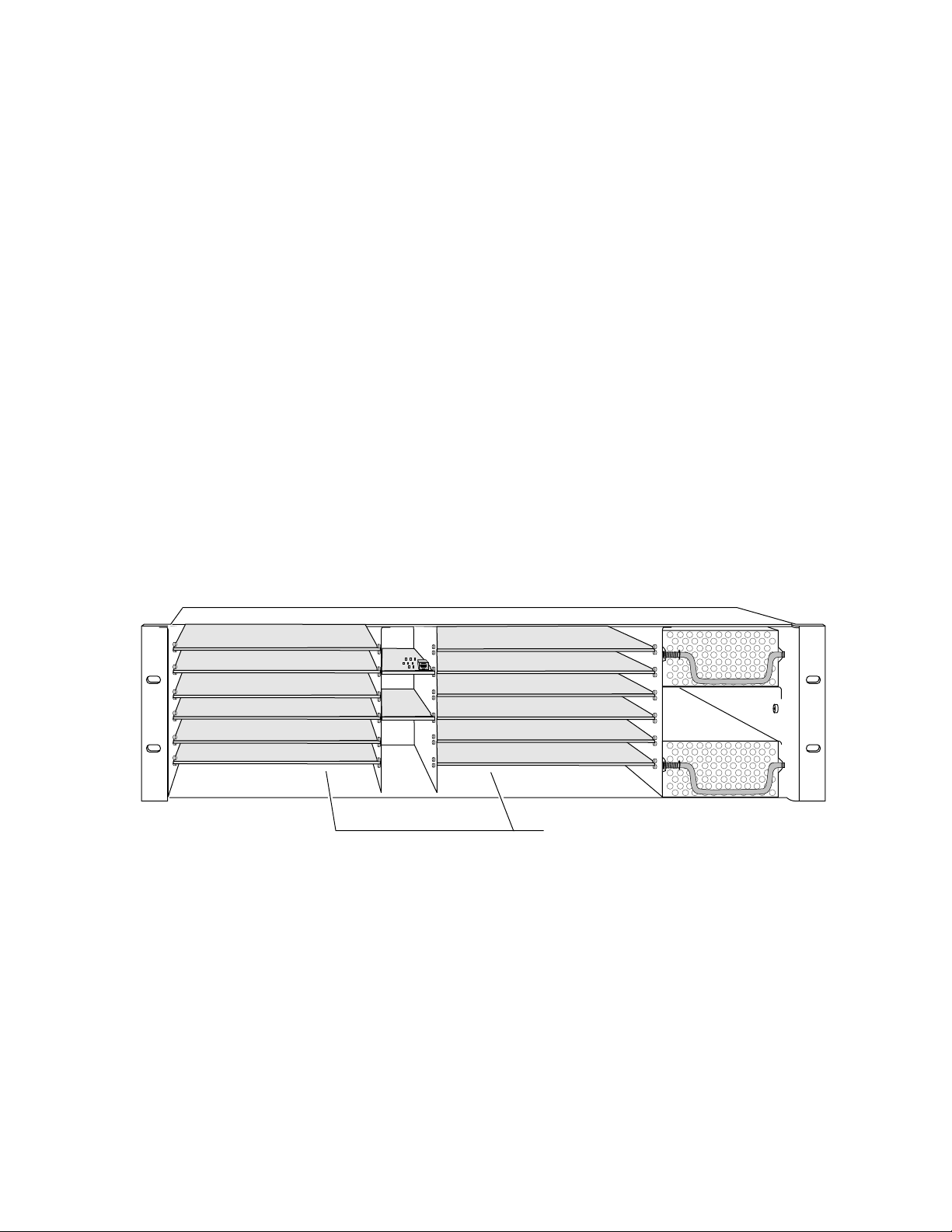
Module Placement in the 2000 Frame
There are twelve cell locations in the 3 RU frame to accommodate either
analog or digital modules. The 2090MDC consists of a two module set con-
sisting of a front media module and a passive rear module. Each 2090MDC
media module plugs into the front of the 2000 frame mid-plane as illus-
trated in Figure 1. The passive rear module plugs into the corresponding
rear slot to provide the input and output interface connectors.
Figure 1. 2000 Series Frame, Front Slots
(1)
(2)
(3)
(4)
(5)
(6)
(7)
(8)
(9)
(10)
(11)
(12)
Front Media Modules
Slots 1-12
Install the passive rear module first by inserting it into any rear slot
(1 – 12) of the frame as illustrated in Figure 2.
8029-04
2 2090MDC Instruction Manual
Page 9
Alignment post
and receptacle
Screw lock
(both sides)
8024_05r1
2000 frame (rear view)
2090MDC Passive Rear Module
Board edge guides
(both sides)
J10J9J8 J7J6J5J4J3J2J1
RBGComp2Comp1SD Out2SD Out1HD Out2HD Out1HD In
2090MDC
2.
3.
4.
5.
6.
Installation
Figure 2. Installing Passive Rear Module
Figure 3. Installing Front Media Module
Board edge
guides
2000
Verify that the module connector seats properly against the midplane.
Secure the module to the rear of the frame with the two screw locks on
either side of the back panel using a crossblade screwdriver.
2000 Frame (front view)
Alignment post and receptacle
Board edge
guides
8023-06
With the component side up, insert the front media module in the
corresponding front slot (see Figure 3).
Verify that the module connector seats properly against the midplane
and rear module connector.
2090MDC Instruction Manual 3
Press firmly on both ejector tabs to seat the module.
Page 10

2090MDC HDTV Monitoring Downconverter
Cabling
All cabling to the 2090MDC module is done on the corresponding passive
rear module at the back of the 2000 frame. Refer to Figure 4 for a detailed
illustration of the rear connections referenced below.
Inputs
Outputs
Note
At the back of this manual are overlay cards that can be placed over the BNC
connectors to identify specific 2090MDC connector functions.
Connect an HD video input to BNC J10. The 2090MDC will accept any of
the HD video standards listed in the Serial HD Input specifications in
Table 5 on page 17.
Connect video monitors to the following outputs provided on the passive
rear module:
■
HD Out1 and HD Out 2 – two output BNCs (J8/J9)
■
SD Out1 and SD Out2 – two serial digital output BNCs (J6/J7)
NTSC/PAL composite – two output BNCs (J4/J5)
■
■
Component analog – three output BNCs (J3–Y/G, J2–U/B, J1–V/R)
Figure 4.
2090MDC
Input/Output Connectors
RBGComp2Comp1SD Out2SD Out1HD Out2HD Out1HD In
2090MDC
J10 J9 J8 J7 J6 J5 J4 J3 J2 J1
8029_03
4 2090MDC Instruction Manual
Page 11

Power Up
Operation Indicator LEDs
Power Up
The front LED indicators and configuration switches are illustrated in
Figure 5. Upon power-up, the green PWR LED should light and the yellow
CONF LED should illuminate for the duration of module initialization.
With factory default configuration and a valid input signal connected, the
green PWR LED and one of the input and output standard LEDs should be
on. Refer to Table 1 on page 6 to see a complete list of possible operating
conditions and the resulting indicator status.
Figure 5. LEDs and Configuration Switches
50 Hz (green)
59.94 Hz (green)
60 Hz (green)
Mode 1 (yellow)
Mode 2 (yellow)
Mode 3 (yellow)
Mode 4 (yellow)
FAULT (red)
COMM (yellow)
CONF (yellow)
PWR (green)
1080i (green)
1035i (green)
720p (green)
8029_01
2090MDC Instruction Manual 5
Page 12

2090MDC HDTV Monitoring Downconverter
A red FAULT LED indicates an error situation and, when noted with the
other indicator LEDs, can indicate a specific problem area. Table 1 describes
signal output and LED indications for the various input/reference combinations and user settings.
Table 1. Indicator LEDs and Conditions Indicated
LED Indication Condition
Off Normal operation
FAULT (red)
COMM (yellow)
CONF (yellow)
PWR (green)
50 Hz (green)
59.94 Hz (green)
60 Hz (green)
1080i (green)
1035i (green)
720p (green)
Mode 1 (yellow)
Mode 2 (yellow)
Mode 3 (yellow)
Mode 4 (yellow)
On continuously Module has detected internal fault
Long flash Configuration problems, check inputs and settings
Off No activity on frame communication bus
Long flash Location Command received by the module from a remote control system
Short flash Activity present on the frame communication bus
Off Module is in normal operating mode
On continuously Module is initializing, changing operating modes or updating firmware
Off No power to module or module’s DC/DC converter failed
On continuously Normal operation, module is powered
On Indicates field rate of input signal is 50 Hz
On Indicates field rate of input signal is 59.94 Hz
On Indicates frame rate of input signal is 60 Hz
On Indicates input signal standard is 1080i
On Indicates input signal standard is 1035i
On Indicates input signal standard is 720p
On Monitor output display mode is set for letterbox mode
On Monitor output display mode is set for amorphous mode
On Monitor output display mode is set for Full Screen mode
On Monitor output display mode is set for Zoom mode
Table 2 provides the possible input and output conditions and LED states
that result from different input signals.
Table 2. Input and Output Conditions
Input Signal Standard LED Field/Frame Rate LED Output Signal
No signal or invalid signal All LEDs off All LEDs off No valid output
1080i/50 Hz 1080i 50 Hz PAL
1080i/59.94 Hz 1080i 59.94 Hz NTSC
1080i/60 Hz 1080i 60 Hz NTSC
1035i/59.94 Hz 1035i 59.94 Hz NTSC
1035i/60 Hz 1035i 60 Hz NTSC
720p/59.94 Hz 720p 59.94 Hz NTSC
720p/60 hz 720p 60 hz NTSC
6 2090MDC Instruction Manual
Page 13

Configuration
Monitor Output Display Modes Description
Configuration
The 2090MDC can be configured locally using on-board switches and
jumpers or remotely using the 2000NET network interface.
The following parameters can be set on the 2090MDC module:
■
Monitor output display mode,
Pedestal on and off (525 rate only),
■
■
Zoom factor (Zoom mode only),
■
Horizontal position (Full Screen and Zoom mode), and
Control mode – Local/remote or local control only (remote control
■
lockout).
The 2090MDC module provides Letterbox, Amorphous, Full Screen,
and Zoom monitor output modes. Each is explained below and illustrated in Figure 6 on page 8.
Note
In modules with line rate inputs of 525 lines/frame, the pedestal level can
be turned on or off in all four modes.
Letterbox Mode
In Letterbox mode, the whole HD picture is converted to a full SD
picture with horizontal resolution of 720 horizontal pixels and vertical
resolution of 360 (NTSC) or 430 (PAL) lines (per frame).
Amorphous Mode
In Amorphous mode, the whole HD picture is converted to a full SD
picture with horizontal resolution of 720 horizontal pixels and vertical
resolution of 486 (NTSC) or 576 (PAL) lines. No picture information is
lost but vertical stretch occurs causing objects on screen to appear taller.
2090MDC Instruction Manual 7
Page 14

2090MDC HDTV Monitoring Downconverter
;
Figure 6. Monitor Output Mode Examples
Letterbox – Mode 1
Complete picture in
Letterbox format with
blanking at top and bottom
Amorphous – Mode 2
Complete picture with vertical
distortion (objects appear taller),
no blanking at top or bottom
Zoom
Shift to left
Shift to left
Zoom
Zoom
Shift to right
Shift to right
Zoom
Full Screen – Mode 3
Complete picture with no distortion
can be shifted left or right
= Horizontal shift
Zoom – Mode 4
Complete picture which can zoom
from letterbox to full screen with
horizontal shift adjustment at any
zoom level greater than minimum
letterbox
= Horizontal shift
8 2090MDC Instruction Manual
Page 15

Configuration
Full Screen Mode
The Full Screen mode provides a monitor output with a complete SD
picture with no distortion. The picture display can be shifted to the left or
right with the on-board paddle switch, or set remotely in the Mode and
Signal Standard display.
The horizontal shift occurs in steps of eight pixels of the input signal. The
maximum number of pixels the display can be moved horizontally differs
in each input standard. The maximum number of pixels that can be shifted
for the three input standards are given in Table 3.
Table 3. Horizontal Shift Values In Full Screen and Zoom Mode
Input Standard Maximum Steps
1080i 60 steps (8 pixels per step)
1035i 68 steps (8 pixels per step)
720p 40 steps (8 pixels per step)
Zoom Mode
The Zoom mode outputs display that can be zoomed in size from letterbox
(minimum) to undistorted full screen (maximum). The display can be
shifted from left to right with the on-board paddle switch or set remotely
in the Mode and Signal Standard display.
In Zoom mode, the maximum number of pixels the display can be moved
horizontally is a function of the input standard (Table 3) and the magnitude
of the zoom. The horizontal shift occurs in steps of eight pixels of the input
signal. At maximum Full Screen zoom factor the maximum number of
pixels can be moved. At minimum Letterbox mode, no horizontal shift is
possible.
2090MDC Instruction Manual 9
Page 16

2090MDC HDTV Monitoring Downconverter
Local On-board Module Configuration
The 2090MDC module can be configured locally using the jumper, and
rotary and paddle switches shown in Figure 7. The CONF LED indicates
status of the configuration process.
These components perform the following:
Jumper JP5 – sets control mode for Local only or Remote and Local.
■
■
SW 1 Function (rotary) switch – selects functions performed by paddle
switch SW2. Refer to Table 4 for details.
■
SW2 (paddle) switch – executes the functions selected by rotary switch.
Refer to Table 4 for details.
■
CONF (configuring) LED – when on, indicates the module is initializing or processing configuration information.
Figure 7. Module Configuration Jumpers and Switches
JP5
CONF – Configuration
processing LED
SW1 – Function rotary switch
SW2 – Paddle switch for executing function selections
Remote Control Jumper
When the jumper is placed across pins 1 and 2 of jumper block JP5 (see
Figure 7), module output mode settings are adjustable from the local on-
board switches only. To have both local and remote access, set the jumper
across pins 2 and 3.
Remote Control Lockout
LOCAL
LOCAL & REM
Jumper across pins 1–2
locks out remote control
1
Jumper across pins 2–3
enables remote and
local control
8029_06
10 2090MDC Instruction Manual
Page 17

Configuring Output Modes and Mode Parameters
To select the output modes and set other mode parameters with the local
on-board switches, refer to the instructions below and Table 4.
1.
2.
3.
Configuration
2
Use the Function rotary switch, SW1, shown in Figure 7 on page 10 and
at left, to enter each Function selection 1 through 4.
When a function has been selected, use the paddle switch, SW2, to
perform the selected functions by moving the paddle switch left or
right according to the instructions in the table below.
Note
In Full Screen and Zoom mode the number of pixels that can be shifted horizontally per step of the paddle switch depends on the input standard and
zoom magnitude as detailed in Table 3 on page 9.
Holding the paddle switch in the left or right position will increase the
number of steps in the functions below, whether zoom factor or
horizontal shift. The number of steps will depend on the length of time
the switch is held in either position and the starting value of the
horizontal position or zoom.
Table 4. 2090MDC Mode Configurations
Rotary
Switch
Position
0 – – – Inactive
1
2
3
4 Setup Level 7.5% 0%
5-F – – – Inactive
Function
Name
Mode
Select:
Left/Right
Shift:
Zoom In/
Zoom Out:
Paddle
Switch
Left
Select Select
Left Right
Zoom In Zoom Out
Paddle
Switch
Right
Function Description
Use paddle switch to select output mode from Letterbox, Amorphous, Full Screen or
Zoom. Choice will be indicated by front Mode LEDs (yellow).
In Full Screen and Zoom Mode, use the paddle switch to move the display to left or
right. Note that full Letterbox mode (minimum zoom) is not adjustable.
In Zoom Mode, use the paddle switch to zoom in and out. Minimum is Letterbox
(right), maximum is Full Screen (left).
In all modes with 525 line rate input, use the paddle switch to set pedestal level to
7.5% (left) or 0% (right). Not active in 625 Hz line rate input.
2090MDC Instruction Manual 11
Page 18

2090MDC HDTV Monitoring Downconverter
Remote Configuration and Monitoring
2090MDC configuration and monitoring can be performed remotely using
the2000NET interface (see Figure 8). This section describes the GUI access
to the module configuration functions. Refer to the 2000NET Network
Interface Module Instruction Manual for information on setting up and
operating the 2000 frame network.
For remote access, make sure jumper block JP5 on the module is set for both
Local and Remote access (Figure 5).
Note
Figure 8. 2000NET GUI
The Links section lists the frame and its current modules. The selected link's Status
page is first displayed and the sub-list of links for the selection is opened. The sub-list
allows you to select a particular information page for the selected device.
The physical appearance of the menu displays shown in this manual repre-
sent the use of a particular platform, browser and version of 2000NET
module software. They are provided for reference only. Displays will differ
depending on the type of platform and browser you are using and the version
of the 2000NET software installed in your system.
Content display section displays the information page
for the selected frame or module (frame slot icons are also
active links).
0612-13
The 2000 modules can be addressed by clicking on a specific module icon
in the frame status display or on a module name or slot number in the link
list on the left.
12 2090MDC Instruction Manual
Page 19

The 2090MDC will indicate a SMPTE Alarm fault on the Frame Status
display for the following alarms:
■
Internal fault,
Configuration fault, or
■
■
Data error.
Module Configuration Displays
The 2000 GUI provides the following links and displays for the 2090MDC
module (Figure 9):
■
Module Configuration displays showing status and slot configuration
information (location and user assigned names),
Signal Configuration displays, and
■
Configuration
■
Software Update display.
The Module Configuration displays are the same for all remote controllable
2000 modules. Refer to the 2000NET manual for more information on these
displays. Some functions listed may not be supported by a particular
module. These will be indicated as not supported.
Figure 9. 2090MDC Display Links
Module Configuration
Displays
Signal Configuration
Display
Software Update
Display
Software Update Displays
The Software Update display allows you to download new software versions for the module. Refer to the 2000NET manual and the Grass Valley
Group web site at http://www.grassvalleygroup.com for complete details
and new software versions.
Signal Configuration Displays
This section discusses the Signal Configuration Displays available to set
and monitor the 2090MDC module parameters remotely.
2090MDC Instruction Manual 13
Page 20

2090MDC HDTV Monitoring Downconverter
Mode and Signal Standard
The Mode and Signal Standard display is shown in Figure 10. After
selecting a mode, select the Apply button to activate it. The displays for
each mode will differ and are illustrated in this section.
Each display will report the following items for the current module status:
■
Input Standard (1080i, 1035i, 720p or No input),
Field Rate (50 Hz, 59.94 Hz, or 60 Hz), and
■
■
Output Standard (525 or 625).
This display provides controls for setting the following functions on the
Use
This
Link
2090MDC module:
■
Monitor output mode (Letterbox, Amorphous, Full Screen or Zoom).
Refer to
Monitor Output Display Modes Description on page 7
on each mode.
for details
Select mode of output monitor
to one of the following:
Set pedestal level of output
to On or Off (all modes).
■
Pedestal on and off for all modes (525 line rate only).
■
Horizontal Shift in Full Screen mode (Figure 11).
Zoom factor (minimum letterbox to maximum full screen) and hori-
■
zontal shift in Zoom mode (Figure 12).
Figure 10. Mode and Signal Standard Display
14 2090MDC Instruction Manual
Page 21

Configuration
Adjust horizontal position
of full screen with slider
When Letterbox or Amorphous modes are chosen, the display will be
similar to the illustration in Figure 10. If the Output Standard is 525, the
Pedestal selection will appear and allow control of the setup level to on or
off. Select the desired condition and select the Apply button to activate it.
The Pedestal selection will not appear when the module is operating with
a 625 line rate.
When Full Screen mode is chosen, the display will appear similar to that of
Figure 11. Refer to the explanation for
Full Screen Mode on page 9
for com-
plete details on this mode.
Use the FS Horizontal Pos. slider to move the Full Screen display to the left
or right. Use the single (1X) or double arrows (10X), then press the Apply
button.
Note that when using the single arrow, each step change (approximately
eight pixels in either direction) may require up to seven clicks of the single
arrow. This is due to the division of the bar display into 256 steps. Shifting
the display is a function of the maximum number of steps for the input
standard divided by 256.
To determine exactly how many clicks will move the display one step if this
is required, refer to Table 3 on page 9. Make the approximate number of
clicks before pressing the Apply button. The returned bar position will be
an approximate (rounded off) value. The double arrows will increment the
display by approximately 10 times in the same manner.
Figure 11. Full Screen Output Mode Display
2090MDC Instruction Manual 15
Page 22

2090MDC HDTV Monitoring Downconverter
In Zoom mode (Figure 12), use the Zoom slider to set the zoom factor from
full letterbox (minimum) to full screen (maximum). Use the single (1X) or
double arrows (10X), then press the Apply button.
The Zoom magnitude has 35 possible values. To increment the Zoom by
one step will require up to eight clicks on the single arrow due to the
number of divisions of the bar display. Make the approximate number of
clicks before pressing the Apply button. One double arrow click will increment the Zoom by one step.
Use the Zoom Horizontal Pos. slider to move the display to the left and
right. Use the single (1X) or double arrows (10X), then press the Apply
button. (Note that in minimum full letterbox mode, the horizontal display
is not adjustable.)
Note that when using the single arrow, each step change (approximately
eight pixels in either direction) may require up to seven clicks of the single
arrow. This is due to the division of the bar display into 256 steps. Shifting
the display is a function of the maximum number of steps for the input
standard divided by 256. A larger number of clicks will be required when
the picture has been zoomed down to less than Full Screen size.
Set Zoom factor with
slider (from letterbox
to full screen).
To determine exactly how many clicks will move the display one step if this
is required, refer to Table 3 on page 9. Make the approximate number of
clicks before pressing the Apply button. The returned bar position will be
an approximate (rounded off) value. The double arrows will increment the
display by approximately 10 times in the same manner.
Figure 12. Zoom Mode Display
Set Zoom horizontal position
with slider (adjustable from greater
than full letterbox to full screen).
16 2090MDC Instruction Manual
Page 23

Specifications
Specifications
Table 5. 2090MDC Specifications
Parameter Value
Serial HD Input
Number and type of inputs 1 BNC
Input impedance 75 Ohm
Input signal formats 1.5 Gbit serial digital conforming to the following SMPTE formats:
240M (1920/1035i 59.94/60 Hz),
274M (1920/1080i 59.934/60 Hz)
295M (1920/1080i 50 Hz)
296M (1280/720p 59.94/60 Hz)
Signal level 800 mV ±10%
Return loss >15 dB to 1.5 GHz
Serial HD Outputs
Number and type of outputs 2 BNC
Output impedance 75 Ohm
Output signal formats 1.5 Gbit serial digital conforming to the following SMPTE formats:
240M (1920/1035i 59.94/60Hz),
274M (1920/1080i 59.934/60 Hz)
295M (1920/1080i 50 Hz)
296M (1280/720p 59.94/60 Hz)
Output level 800 mV ± 10%
Return loss >10 dB to 1.5 GHz
Serial Digital Outputs
Number and type of outputs 2 BNC
Output impedance 75 Ohm
Signal type Serial digital video conforming to SMPTE 259M 10-bit 4:2:2 com-
ponent standard
Signal level 800 mV ±10%
Return loss >15 dB to 270 MHz
NTSC/PAL Analog Composite Outputs
Number and type of outputs 2 BNC
Output impedance 75 Ohm
Signal type Conforming to SMPTE 170M (NTSC), CCIR-624 (PAL)
Signal level 1 V p-p
Differential gain 0.3%
Differential phase 0.4 °
Luminance nonlinearity ± 1%
Chroma nonlinear gain ± 1.2%
Chroma nonlinear phase ± 0.3 °
Frequency response – luma ± 0.1 dB @ 5.5 MHz
Frequency response – chroma -2 dB @ 1.3 MHz
Return loss > 40 dB to 5.5 MHz
Analog Component Outputs
2090MDC Instruction Manual 17
Page 24

2090MDC HDTV Monitoring Downconverter
Table 5. 2090MDC Specifications - (continued)
Parameter Value
Number and type of outputs 3 BNC
Output impedance 75 Ohm
Signal type Component analog video (SMPTE 253M)
Signal level 1 V p-p nominal
Return loss > 40 dB to 5.5 MHZ
Performance
Aspect ratio modes Letterbox, amorphous, full screen, zoom
Power < 15 W
Environmental
Frame temperature range 0 to 45 ° C
Operating humidity range 0 to 90% non condensing
Non-operating temperature -10 to 70 ° C
18 2090MDC Instruction Manual
Page 25

Service
Power-up Diagnostics Failure
Troubleshooting
Service
The 2090MDC modules make extensive use of surface-mount technology
and programmed parts to achieve compact size and adherence to
demanding technical specifications. Circuit modules should not be serviced in the field unless otherwise directed by Customer Service.
If the module has not passed self-diagnostics, do not attempt to troubleshoot. Return the unit to Grass Valley (see Module Repair).
If your module is not operating correctly, proceed as follows:
■ Check frame and module power. If power is not present, check the fuse
on the front Media module as illustrated in Figure 13.
Module Repair
■ Check for presence and quality of input signals.
■ Verify that source equipment is operating correctly.
■ Check cable connections.
Figure 13. Location of Front Module Fuse
Fuse F1
2A, 125V F
8029-08
2000
If the module is still not operating correctly, replace it with a known good
spare and return the faulty module to a designated Grass Valley repair
depot. Call your Grass Valley representative for depot location.
Refer to Contacting Grass Valley Group at the front of this document for the
Grass Valley Customer Service Information number.
2090MDC Instruction Manual 19
Page 26

2090MDC HDTV Monitoring Downconverter
Functional Description
A block diagram of the 2090MDC is shown in Figure 14.
Figure 14. 2090MDC Block Diagram
SERIAL
HD in
Equalizer
&
Reclocker
Y
UV
H
Halfband
Filters
HD FPGA
Field/Frame
Buffers
Input
Timing
&
Control
UV
HD
Out
UV
Colorimetry
Y
UV
UVFIFO
Scaling
Y
Engine
Y
Y-FIFO
Converter
D1
Multiplexer
SD
Timing
SD FPGA
NTSC
Encoder
&
RGB
Converter
D1
Serializer
&
Scrambler
SD
Driver
NTSC/PAL
Out
R
Out
G
B
SD
Out
Input Processing
The input section equalizes, re-clocks and de-serializes the HD input
signal.
One equalized and reclocked version of the input is fed back to the rear
looping BNC connector assembly through an output driver to become the
two HD outputs.
Scaler
The parallel video from the input processor is filtered and decimated in the
field/frame buffer in the HD FPGA and enters the scaling engine IC. Video
data from the Input Processing section is scaled down so that it will fit onto
a standard definition screen. The amount and type of scaling is programmed by the user; locally, by setting on-board switches, or remotely
through the frame controller.
8029_02
Microprocessor
20 2090MDC Instruction Manual
Page 27

UV and Y FIFOs
The UV and Y FIFOs act as buffers between the output of the scaler and the
monitor output section. The FIFOs perform field rate conversion from
60 Hz to 59.94 Hz.
Colorimetry Converter
The colorimetry converter converts the color value from the coding matrix
used for HD video (ITU BT 709) to the corresponding value (ITU BT 601) in
the standard definition coding matrix. This conversion is done in the SD
FPGA.
Multiplexer
The multiplexer section of the SD FPGA multiplexes the Y and UV data into
one D1 data string.
Functional Description
NTSC/RGB Encoder
The D1 signal from the Multiplexer splits off and one path enters the NTSC
Encoder and RGB Converter circuitry. The digital parallel data in D1
format is encoded into analog NTSC and also converted to analog RGB.
These signals are fed through output drivers to the two looping BNCs for
NTSC/PAL video and a set of RGB outputs for feeding component monitors.
Scrambler and Serializer
The other D1 signal path from the Multiplexer enters Scrambler and Serializer circuitry which converts the output into two SDI outputs. These SDI
outputs are sent to an SD driver and then to the rear connector assembly as
the two 601 outputs.
Timing
Each FPGA contains timing circuitry to generate all necessary input and SD
video timing signals needed by the other components. An output pixel
clock is also produced via a phase lock loop locked to the input bit rate.
2090MDC Instruction Manual 21
Page 28

2090MDC HDTV Monitoring Downconverter
Microcontroller
The microcontroller configures the other components:
■ At power up,
■ When the standard of the input signal changes, and
■ When the user changes the output display mode using the front panel
pushbuttons or remote control settings.
22 2090MDC Instruction Manual
Page 29

Index
Numerics
1035i LED 6
1080i LED 6
2000NET module 13
50 HZ LED 6
59.94 LED 6
60 HZ LED 6
720P LED 6
A
amorphous mode 7, 15
B
block diagram 20
C
cabling
inputs
outputs 4
circuit descriptions 20
COMM LED 6
CONF (configuring) LED 6, 10
configuration 7
local on-board 10
remote 12
4
E
frame status display 12
frame, 3RU 2
full screen mode 9, 15
function rotary switch 10, 11
fuse 19
G
GUI 12, 13
I
inputs 4
installation 2
L
LEDs 5
letterbox mode 7, 15
M
media module 2
installation 3
midplane 3
MODE 1 LED 6
MODE 2 LED 6
MODE 3 LED 6
MODE 4 LED 6
Mode and Signal Standard display 14
environmental 18
N
network 12
F
factory default 5
FAULT LED 6
fault report 13
fault table 6
features 1
2090MDC Instruction Manual Index-1
O
output modes
local configuration
remote configuration 14
outputs 1, 4
11
Page 30

overlays 4
P
paddle switch 10, 11
passive rear module 2
installation 2
pedestal level 7, 11, 14, 15
PWR LED 5, 6
R
remote control displays
Mode and Signal Standard
remote control lockout 10
jumper 10
repair depot 19
14
S
setup level (see pedestal level) 11
SMPTE alarm 13
software update 13
specifications 2, 17
analog output 17
NTSC/PAL Outputs 17
serial digital outputs 17
serial HD input 17
serial HD outputs 17
T
troubleshooting 19
Z
zoom mode 9, 16
Index-2 2090MDC Instruction Manual
 Loading...