

Page 1

2042EDA
DUAL WIDEBAND EQUALIZING DA
Instruction Manual
071806600
FIRST PRINTING: JANUARY 2001
1.0software release
Page 2

Contacting Grass Valley Group
Region Voice Fax Address Web Site
North America (800) 547-8949
530-478-4148
Pacific Operations +852-2585-6688
Support: 852-2585-6579
U.K., Europe, Asia, Middle East +44 1753 218 777 +44 1753 218 757
France +33 1 45 29 73 00
Germany +49 221 1791 234 +49 221 1791 235
Copyright © Grass Valley Group. All rights reserved.
This document may not be copied, in whole or in part, or otherwise reproduced, except as specifically
permitted under U.S. copyright law, without the prior written consent of Grass Valley Group, P.O. Box
599000, Nevada City, CA 95959-7900 USA. GRASS VALLEY GROUP is a registered trademark and
Grass Valley is a trademark of Grass Valley Group. All registered trademarks and trademarks are property of their respective holders. Grass Valley Group products are covered by U.S. and foreign patents,
issued and pending. Product options and specifications subject to change without notice. The information in this manual is furnished for informational use only, is subject to change without notice, and
should not be construed as a commitment by Grass Valley Group. Grass Valley Group assumes no responsibility or liability for any errors or inaccuracies that may appear in this publication.
(530) 478-3347 Grass Valley Group
+852-2802-2996
P.O. Box 599000
Nevada City, CA 95959-7900
USA
www.grassvalleygroup.com
Page 3

Contents
Preface
About This Manual . . . . . . . . . . . . . . . . . . . . . . . . . . . . . . . . . . . . . . . . . . . . . . . . . . . . . v
2042EDA Dual Wideband Equalizing Distribution Amplifier
Introduction . . . . . . . . . . . . . . . . . . . . . . . . . . . . . . . . . . . . . . . . . . . . . . . . . . . . . . . . . . . 1
Installation . . . . . . . . . . . . . . . . . . . . . . . . . . . . . . . . . . . . . . . . . . . . . . . . . . . . . . . . . . . . 2
Module Placement in the 2000 Frame. . . . . . . . . . . . . . . . . . . . . . . . . . . . . . . . . . . . 2
Cabling . . . . . . . . . . . . . . . . . . . . . . . . . . . . . . . . . . . . . . . . . . . . . . . . . . . . . . . . . . . . . 5
Inputs. . . . . . . . . . . . . . . . . . . . . . . . . . . . . . . . . . . . . . . . . . . . . . . . . . . . . . . . . . . . . 5
Outputs . . . . . . . . . . . . . . . . . . . . . . . . . . . . . . . . . . . . . . . . . . . . . . . . . . . . . . . . . . . 5
Power Up . . . . . . . . . . . . . . . . . . . . . . . . . . . . . . . . . . . . . . . . . . . . . . . . . . . . . . . . . . . . . 6
Operation Indicator LEDs . . . . . . . . . . . . . . . . . . . . . . . . . . . . . . . . . . . . . . . . . . . . . 6
Configuration and Monitoring . . . . . . . . . . . . . . . . . . . . . . . . . . . . . . . . . . . . . . . . . . . 8
Remote Monitoring . . . . . . . . . . . . . . . . . . . . . . . . . . . . . . . . . . . . . . . . . . . . . . . . . . . 8
Module Configuration Displays . . . . . . . . . . . . . . . . . . . . . . . . . . . . . . . . . . . . . . 9
Software Update Displays . . . . . . . . . . . . . . . . . . . . . . . . . . . . . . . . . . . . . . . . . . . 9
Specifications . . . . . . . . . . . . . . . . . . . . . . . . . . . . . . . . . . . . . . . . . . . . . . . . . . . . . . . . . 10
Service. . . . . . . . . . . . . . . . . . . . . . . . . . . . . . . . . . . . . . . . . . . . . . . . . . . . . . . . . . . . . . . 12
Power-up Diagnostics Failure . . . . . . . . . . . . . . . . . . . . . . . . . . . . . . . . . . . . . . . . . 12
Troubleshooting. . . . . . . . . . . . . . . . . . . . . . . . . . . . . . . . . . . . . . . . . . . . . . . . . . . . . 12
Module Repair . . . . . . . . . . . . . . . . . . . . . . . . . . . . . . . . . . . . . . . . . . . . . . . . . . . . . . 12
Functional Description . . . . . . . . . . . . . . . . . . . . . . . . . . . . . . . . . . . . . . . . . . . . . . . . . 13
Input Processing . . . . . . . . . . . . . . . . . . . . . . . . . . . . . . . . . . . . . . . . . . . . . . . . . . . . 13
Microprocessor. . . . . . . . . . . . . . . . . . . . . . . . . . . . . . . . . . . . . . . . . . . . . . . . . . . . . . 13
Output Processing . . . . . . . . . . . . . . . . . . . . . . . . . . . . . . . . . . . . . . . . . . . . . . . . . . . 14
Power Supply. . . . . . . . . . . . . . . . . . . . . . . . . . . . . . . . . . . . . . . . . . . . . . . . . . . . . . . 14
Index
2042EDA Instruction Manual iii
Page 4

Contents
iv 2042EDA Instruction Manual
Page 5

Preface
About This Manual
This manual describes the features of a specific module of the 2000 Series
Modular Products family. As part of this module family, it is subject to
Safety and Regulatory Compliance described in the 2000 Series frame and
power supply documentation (see the
2000 Frames Instruction Manual
).
2042EDA Instruction Manual v
Page 6

Preface
vi 2042EDA Instruction Manual
Page 7

2042EDA Dual Wideband
Equalizing Distribution
Amplifier
Introduction
The 2042EDA Dual Wideband Equalizing DA provides two wideband
channels for equalization and distribution of standard or high definition
input signals (4 Mb/s to 1.5 Gb/s) to four outputs each. The module set
includes a media module that resides in the front of a 2000 Series frame and
a passive rear module for input and output connections.
The features of the 2042EDA include:
■
Auto equalization of standard and high definition signals,
■
Accepts a wide range of standard or high definition input signal standards,
■
Use of non-inverted outputs allow distribution of compressed signals
such as SMPTE 310M and DVB-ASI, and
■
Remote monitoring support.
2042EDA Instruction Manual 1
Page 8
2042EDA Dual Wideband Equalizing Distribution Amplifier
Installation
Installation of the 2042EDA module set is a process of:
Placing the passive rear module in a frame slot,
■
■
Placing the media module in the corresponding front slot, and
■
Cabling and terminating signal ports.
The 2042EDA module can be plugged in and removed from a 2000 Series
frame with power on. When power is applied to the module, LED indica-
tors reflect the initialization process (see Power Up on page 6).
Module Placement in the 2000 Frame
There are twelve slot locations in both the front and rear of a 3RU frame to
accommodate 2000 Series modules. The 2042EDA consists of a two module
set with a front media module and a passive rear module that can be
plugged into any of the 12 frame slots. Each 2042EDA front media module
plugs into the front of the 2000 frame mid-plane. The passive rear module
plugs into the corresponding rear slot to provide the input and output
interface connectors.
Mid-frame motherboard
with power and
communication buses
To install a 2042EDA module set in the frame:
1.
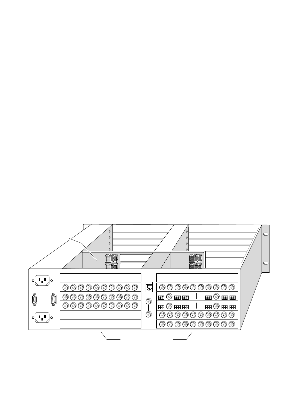
Locate a vacant slot in the rear of the 3 RU frame (Figure 1).
Figure 1. 3 RU Frame, Rear View
8025-04
12 rear media module slots
2 2042EDA Instruction Manual
Page 9

2.
3.
4.
Installation
Insert the passive rear module into any vacant rear slot (1 – 12) of the
frame as illustrated in Figure 2.
Figure 2. Installing Passive Rear Module
2000 frame (rear view)
Alignment post
and receptacle
In 1 Out 1A Out 1B Out 1C Out 1D In 2 Out 2A Out 2B Out 2C Out 2D
J10
SIG J9 J8 J7 J6 J5 J4 J3 J2 J1
2042EDA Rear Module (overlay installed)
Verify that the module connector seats properly against the midplane.
Using a crossblade screwdriver, tighten the two screw locks to secure
the module in the frame.
5.
Install the overlay provided at the rear of this manual (hard copy only)
for input and output locations.
Board edge guides
(both sides)
2042EDA
Screw lock
(both sides)
8066_01
2042EDA Instruction Manual 3
Page 10

6.
7.
8.
2042EDA Dual Wideband Equalizing Distribution Amplifier
Locate the corresponding front slot in the frame. The 3 RU frame front
view is illustrated in Figure 3.
Figure 3. 2000 Series 3 RU Frame, Front Slots
(1)
(2)
(3)
(4)
(5)
(6)
(7)
(8)
(9)
(10)
(11)
(12)
Front Media Modules
Slots 1-12
With the component side up, insert the front media module in the
corresponding front slot (see Figure 4).
Verify that the module connector seats properly against the midplane
and rear module connector.
9.
Press firmly on both ejector tabs to seat the module.
Figure 4. Installing Front Media Module
2000 Frame (front view)
Alignment post and receptacle
8066-03
Board edge
guides
2042EDA
Board edge
guides
8066-07
4 2042EDA Instruction Manual
Page 11

Cabling
Inputs
Outputs
Cabling to the 2042EDA module is done on the BNCs on the passive rear
module. Refer to Figure 5 for a detailed illustration of the rear connections
referenced below.
The 2042EDA will accept any of the video standards listed in the Input
specifications in Table 3 on page 10. Connect a video input to In 1, BNC J10
and In 2, BNC J5.
The 2042EDA outputs conform to the video standards listed in the Output
specifications in Table 3 on page 10.
Installation
Connect video destinations to the four outputs for In 1 at Out 1A – Out 1D
(BNCs J9 – J6 respectively) and the four outputs for In 2 at Out 2A– Out 2D
(BNCs J4 – J1 respectively). Terminate any unused outputs.
Figure 5. 2042EDA Input/Output Connectors (with overlay installed)
In 1 In 2Out 1A Out 1B Out 1C Out 1D Out 2A Out 2B Out 2C Out 2D
J10 SIG J9 J8 J7 J6 J5 J4 J3 J2 J1
Channel 1 Outputs
Channel 2 Outputs
2042EDA
8066_02
2042EDA Instruction Manual 5
Page 12

2042EDA Dual Wideband Equalizing Distribution Amplifier
Power Up
The on-board LED indicators are illustrated in Figure 6. Upon power-up,
the green PWR LED should light and the yellow CONF LED should illuminate for the duration of module initialization.
Operation Indicator LEDs
With valid input signals connected to In 1 and In 2, the green on-board
PWR LED, SIG 1 PRES LED, SIG PRES 2 LED and the SIG LED (visible from
the rear of the passive rear module) should be on. The FAULT LED should
be off.
Refer to Table 1 on page 7 to see a complete list of possible operating con-
ditions and the resulting indicator status.
PRES
PRES
SIG 2
SIG 1
Figure 6. 2042EDA Indicator LEDs
FAULT (red)
COMM (yellow)
CONF (yellow)
PWR (green)
SIG 2 PRES (green)
SIG 1 PRES (green)
8066_04
6 2042EDA Instruction Manual
Page 13

A red FAULT LED indicates an error situation and, when noted with
the other indicator LEDs, can indicate a specific problem area. Table 1
describes signal output and LED indications for the various input/reference combinations.
Table 1. Indicator LEDs and Conditions Indicated
LED Indication Condition
Off Normal operation
FAULT (red)
COMM (yellow)
CONF (yellow)
PWR (green)
SIG 1 PRES
(green)
SIG 2 PRES
(green)
SIG (rear view)
(green)
On continuously Module has detected internal fault
Long flash No input signal on input 1 or input 2
Off No activity on frame communication bus
Long flash Location Command received by the module from a remote control system
Short flash Activity present on the frame communication bus
Off Module is in normal operating mode
On continuously Module is initializing, changing operating modes or updating firmware
Off No power to module or module’s DC/DC converter failed
On continuously Normal operation, module is powered
Off Indicates input 1 signal carrier missing or over EQ range
On Indicates input 1 signal carrier present
Off Indicates input 2 signal carrier missing or over EQ range
On Indicates input 2 signal carrier present
Off Indicates both input 1 and 2 signal carriers missing
On continuously Indicates both input 1 and 2 signal carriers present
Long Flash Indicates input 1 missing, input 2 present
Short Flash Indicates input 1 present, input 2 missing
Power Up
Table 2 provides the possible input and output conditions that result
from different input signals and conditions.
Table 2. Input and Output Conditions
Input Condition Output Condition
Serial Digital Component (SDI) Serial Digital Component (SDI)
HD Digital Component (SDI) HD Digital Component (SDI)
Other carrier (SMPTE 310M, DVB-ASI) Other carrier (SMPTE 310M, DVB-ASI)
No input signal Muted
Cable exceeding 200 – 300 meters Muted
2042EDA Instruction Manual 7
Page 14

2042EDA Dual Wideband Equalizing Distribution Amplifier
Configuration and Monitoring
The 2042EDA has no configuration requirements. There are no local
jumpers or controls on the 2042EDA module.
Remote Monitoring
2042EDA monitoring can be performed remotely using the 2000NET interface (see Figure 7). This section describes the GUI access to the module
monitoring functions. Refer to the 2000NET Network Interface Module
Instruction Manual for information on setting up and operating the 2000
frame network.
Note
The 2000 modules can be addressed by clicking on a specific module icon
in the frame status display or on a module name or slot number in the link
list on the left.
Figure 7. 2000NET GUI
The Links section lists the frame and its current modules. The selected link's Status
page is first displayed and the sub-list of links for the selection is opened. The sub-list
allows you to select a particular information page for the selected device.
The physical appearance of the menu displays shown in this manual repre-
sent the use of a particular platform, browser and version of 2000NET
module software. They are provided for reference only. Displays will differ
depending on the type of platform and browser you are using and the version
of the 2000NET software installed in your system.
Content display section displays the information page
for the selected frame or module (frame slot icons are also
active links).
8026_08
8 2042EDA Instruction Manual
Page 15

Module Configuration Displays
The 2000 GUI provides the following links and displays for the 2042EDA
module (Figure 8):
■
Module Configuration displays showing front and rear module status
and slot configuration information (location and user assigned names),
and
■
Software Update display.
The Module Configuration displays operate in the same manner for all
remote controllable 2000 modules. Refer to the 2000NET manual for more
information on these displays. Some functions listed may not be supported
by a particular module. These will be indicated as not supported.
Figure 8. 2042EDA Display Links
Configuration and Monitoring
Module Configuration
Displays
Software Update
Display
A Rear Module Status display (Figure 9) is provided to check the presence
of the correct passive rear module for the 2042EDA front media module.
One of the following messages will be reported in the Rear Module Present
display:
■
Correct Module,
■
Incorrect Module, or
Module Missing.
■
Figure 9. Rear Module Status Display
Indicates status of
passive rear module
Software Update Displays
The Software Update display allows you to download new software versions for the module. Refer to the 2000NET manual and the Grass Valley
Group web site at http://www.grassvalleygroup.com for complete details
and new software versions.
2042EDA Instruction Manual 9
Page 16

2042EDA Dual Wideband Equalizing Distribution Amplifier
Specifications
Table 3. 2042EDA Specifications
Parameter Value
Serial Digital Component Inputs (Channel 1 and Channel 2)
Number and type of inputs 1 BNC per channel
Input impedance 75 Ω
Input signal type Serial digital component conforming to the following formats:
• SMPTE 292M
• SMPTE 259M (143 Mbps, 177 Mbps, 270 Mbps, 360 Mbps)
• EBU 1697
• 4 Mbps to 1.5 Gbps with PN20 pseudonoise sequence, maximum ratio of 19/1
• SMPTE 310M
• DVB-ASI
Signal level SDI 800 mV ±10% max
Return loss >15 dB to 0.004 to 1.5 GHz
Equalization Auto equalizing:
HD signals: up to 90 m of Belden 8281 cable or 120 m of Belden 1694,
SD signals and other <540 Mbps signals: up to 100 m of Belden 8281 or equivalent
Serial Digital Component Outputs (Channel 1 and Channel 2)
Number and type of outputs 4 BNCs per channel
Output impedance 75 Ω
Signal type Serial digital component conforming to the following formats:
• SMPTE 292M
• SMPTE 259M (143 Mbps, 177 Mbps, 270 Mbps, 360 Mbps)
• EBU 1697
• 4 Mbps to 1.5 Gbps with PN20 pseudonoise sequence, maximum ratio of 19/1
• SMPTE 310M
• DVB-ASI
Signal level SDI 800 mV ±10% max
Return loss >15 dB to 0.004 to 1.5 GHz
Error checking Transparent to embedded EDH
Electrical length 22 ns ±1 ns
Rise and fall time 160 – 270 ps between 20 – 80%
Output polarity Non-inverted
Jitter < 0.2 UI
Modes of Operation
Operating modes Equalizing in wideband mode
Reclocking modes None
Non-reclocking modes 4 Mbps to 1.5 Gbps with maximum P/N ratio of 19/1
Auto mute Output muted for long cable lengths (mute point varies between 200 – 300 m.)
Power
10 2042EDA Instruction Manual
Page 17

Table 3. 2042EDA Specifications
Parameter Value
Input power maximum <7 Watts
Environmental
Frame temperature range 0 to 45 ° C
Non-operating temperature -10 to +70 ° C
Operating humidity range 10% to 90% non-condensing
Specifications
2042EDA Instruction Manual 11
Page 18

2042EDA Dual Wideband Equalizing Distribution Amplifier
Service
The 2042EDA modules make extensive use of surface-mount technology
and programmed parts to achieve compact size and adherence to
demanding technical specifications. Circuit modules should not be serviced in the field unless otherwise directed by Customer Service.
Power-up Diagnostics Failure
If the module has not passed self-diagnostics, do not attempt to troubleshoot. Return the unit to Grass Valley (see
Troubleshooting
Module Repair
).
If your module is not operating correctly, proceed as follows:
■
Check frame and module power. If power is not present, check the fuse
on the +24V input to the module as illustrated in Figure 10.
Check for presence and quality of input signals.
■
■
Verify that source equipment is operating correctly.
■
Check cable connections.
Figure 10. Location of Module Fuse
SIG 2
PRES
SIG 1
PRES
Fuse: 2 A FAST, 125 V
F1
8066_05
Module Repair
If the module is still not operating correctly, replace it with a known good
spare and return the faulty module to a designated Grass Valley repair
depot. Call your Grass Valley representative for depot location.
Refer to
Grass Valley Customer Service Information number.
12 2042EDA Instruction Manual
Contacting Grass Valley Group
at the front of this document for the
Page 19

Functional Description
Serial
SD or
HD in
Serial
SD or
HD in
SIG 1/2 PRES
rear LED
Ch 1
Serial
SD or
HD Out
8066_06
Equalizer
Microprocessor
Signal 1 present
Signal 2 present
Signal 1/2 present
Remote
Control
Input
Amplifier
Equalizer
Input
Amplifier
Output
Drivers
Ch 2
Serial
SD or
HD Out
Output
Drivers
In 1
In 2
Passive
Rear
Module
Connectors
SIG 2 PRES LED
SIG 1 PRES LED
FAULT
LED
COMM LED
CONF LED
PWR LED
A block diagram of the 2042EDA is shown in Figure 11.
Figure 11. 2042EDA Block Diagram
Functional Description
Input Processing
The two wideband channels for serial SD or HD signals enter the module
from rear BNCs J10 (In 1) and J5 (In 2) on the passive rear module to input
amplifiers. The signals are then equalized for specified cable lengths in the
equalizer circuit.
Microprocessor
2042EDA Instruction Manual 13
The main functions of the microprocessor include:
■
■
■
Providing remote control and monitoring capability for the module
(through ethernet),
Communicating with equalizer ICs to monitor signal present status,
and
Relaying module status through on-board LEDs.
Page 20

2042EDA Dual Wideband Equalizing Distribution Amplifier
Output Processing
Driver circuits feed each of the four serial digital outputs for each input to
the rear BNCs J6 – J9 (Out 1A – Out 1D) and J1 – J4 (Out 2A – Out 2D) on
the passive rear module. These outputs are non-inverting and are in-phase
with each other.
Power Supply
Power is fed from +24 V rails of the frame’s switching power supply. The
power input is protected by a socketed fuse (Figure 10). Each amplifier
circuit on the module receives its own, separate, highly regulated and filtered power source to reduce EMI and on-board crosstalk.
14 2042EDA Instruction Manual
Page 21

Index
Numerics
2000NET module
9
B
block diagram
13
C
cabling
inputs
outputs
circuit descriptions
COMM LED
CONF (configuring) LED
configuration
5
5
13
7
8
E
environmental
equalization
11
1
6, 7
L
LEDs
6
M
media module
installation
midplane
monitoring
remote
4
8
N
network
8
O
outputs 5
overlay 3, 5
P
2
4
passive rear module 2
F
FAULT LED
fault table
frame status display
frame, 3RU
fuse
12, 14
6, 7
7
2
8
installation 2
PWR LED 6, 7
R
Rear Module Status display 9
repair depot 12
G
S
GUI
8, 9
I
inputs
installation
2042EDA Instruciton Manual Index-1
5
specifications
2
10
SIG 1 PRES LED 6, 7
SIG 2 PRES LED 6, 7
SIG LED (rear) 6, 7
software update 9
specifications 10
Page 22

T
troubleshooting 12
Index-2 2042EDA Instruciton Manual
Page 23

2042EDA Dual Wideband DA PRM Rear Connector Overlays
Fold along vertical lines to break perforations, then tear to separate vertical strips.
FoldFoldFoldFoldFoldFold
J10 J9 J8 J7 J6 J5 J4 J3 J2 J1
SIG
In1 Out 1A Out 1B
Out 1C Out 1D In 2 Out 2A
J10 J9 J8 J7 J6 J5 J4 J3 J2 J1
SIG
In1 Out 1A Out 1B
Out 1C Out 1D In 2 Out 2A
J10 J9 J8 J7 J6 J5 J4 J3 J2 J1
SIG
In1 Out 1A Out 1B
Out 1C Out 1D In 2 Out 2A
J10 J9 J8 J7 J6 J5 J4 J3 J2 J1
SIG
In1 Out 1A Out 1B
Out 1C Out 1D In 2 Out 2A
J10 J9 J8 J7 J6 J5 J4 J3 J2 J1
SIG
In1 Out 1A Out 1B
Out 1C Out 1D In 2 Out 2A
In1 Out 1A Out 1B
J10 J9 J8 J7 J6 J5 J4 J3 J2 J1
SIG
Out 1C Out 1D In 2 Out 2A
Out 2B Out 2C Out 2D
2042EDA
Out 2B Out 2C Out 2D
2042EDA
Out 2B Out 2C Out 2D
2042EDA
Out 2B Out 2C Out 2D
2042EDA
Out 2B Out 2C Out 2D
2042EDA
Out 2B Out 2C Out 2D
2042EDA
FoldFoldFoldFoldFoldFold
Page 24

2042EDA Dual Wideband Equalizing DA
18 2042EDA Instruction Manual
Page 25

2042EDA Dual Wideband DA PRM Rear Connector Overlays
Fold along vertical lines to break perforations, then tear to separate vertical strips.
FoldFoldFoldFoldFoldFold
J10 J9 J8 J7 J6 J5 J4 J3 J2 J1
SIG
In1 Out 1A Out 1B
Out 1C Out 1D In 2 Out 2A
J10 J9 J8 J7 J6 J5 J4 J3 J2 J1
SIG
In1 Out 1A Out 1B
Out 1C Out 1D In 2 Out 2A
J10 J9 J8 J7 J6 J5 J4 J3 J2 J1
SIG
In1 Out 1A Out 1B
Out 1C Out 1D In 2 Out 2A
J10 J9 J8 J7 J6 J5 J4 J3 J2 J1
SIG
In1 Out 1A Out 1B
Out 1C Out 1D In 2 Out 2A
J10 J9 J8 J7 J6 J5 J4 J3 J2 J1
SIG
In1 Out 1A Out 1B
Out 1C Out 1D In 2 Out 2A
In1 Out 1A Out 1B
J10 J9 J8 J7 J6 J5 J4 J3 J2 J1
SIG
Out 1C Out 1D In 2 Out 2A
Out 2B Out 2C Out 2D
2042EDA
Out 2B Out 2C Out 2D
2042EDA
Out 2B Out 2C Out 2D
2042EDA
Out 2B Out 2C Out 2D
2042EDA
Out 2B Out 2C Out 2D
2042EDA
Out 2B Out 2C Out 2D
2042EDA
FoldFoldFoldFoldFoldFold
Page 26

2042EDA Dual Wideband Equalizing DA
18 2042EDA Instruction Manual
 Loading...