

Page 1

2041EDA
WIDEBAND REAR EQUALIZING DA
Instruction Manual
071803201
FIRST PRINTING: JANUARY 2001
REVISED PRINTING: JANUARY 2003
1.0software release
Page 2

Contacting Grass Valley Group
Region Voice Fax Address Web Site
North America (800) 547-8949
Support: 530-478-4148
Pacific Operations +852-2585-6688
Support: 852-2585-6579
U.K., Europe, Asia, Middle East +44 1753 218 777 +44 1753 218 757
France +33 1 45 29 73 00
Germany +49 221 1791 234 +49 221 1791 235
Copyright © Grass Valley Group. All rights reserved.
This document may not be copied, in whole or in part, or otherwise reproduced, except as specifically
permitted under U.S. copyright law, without the prior written consent of Grass Valley Group, P.O. Box
599000, Nevada City, CA 95959-7900 USA. GRASS VALLEY GROUP is a registered trademark and
Grass Valley is a trademark of Grass Valley Group. All registered trademarks and trademarks are property of their respective holders. Grass Valley Group products are covered by U.S. and foreign patents,
issued and pending. Product options and specifications subject to change without notice. The information in this manual is furnished for informational use only, is subject to change without notice, and
should not be construed as a commitment by Grass Valley Group. Grass Valley Group assumes no responsibility or liability for any errors or inaccuracies that may appear in this publication.
Grass Valley Group Web Site
Sales: (530) 478-3347
Support: (530) 478-3181
+852-2802-2996
Grass Valley Group
P.O. Box 599000
Nevada City, CA 959597900 USA
www.thomsongrassvalley.com
The www.thomsongrassvalley.com web site offers the following:
Online User Documentation
— Current versions of product catalogs, brochures,
data sheets, ordering guides, planning guides, manuals, and release notes
in .pdf format can be downloaded.
FAQ Database
— Solutions to problems and troubleshooting efforts can be
found by searching our Frequently Asked Questions (FAQ) database.
Software Downloads
— Software updates, drivers, and patches can be down-
loaded.
2 2041EDA Instruction Manual
Page 3

Contents
Preface
. . . . . . . . . . . . . . . . . . . . . . . . . . . . . . . . . . . . . . . . . . . . . . . . . . . . . . . . . . . . . . . . . . . . . 5
About This Manual . . . . . . . . . . . . . . . . . . . . . . . . . . . . . . . . . . . . . . . . . . . . . . . . . . . . . 5
2041EDA Wideband Rear Equalizing Distribution Amplifier
Introduction . . . . . . . . . . . . . . . . . . . . . . . . . . . . . . . . . . . . . . . . . . . . . . . . . . . . . . . . . . . 7
Installation . . . . . . . . . . . . . . . . . . . . . . . . . . . . . . . . . . . . . . . . . . . . . . . . . . . . . . . . . . . . 8
Module Placement in the 2000 Frame. . . . . . . . . . . . . . . . . . . . . . . . . . . . . . . . . . . . 8
Cabling . . . . . . . . . . . . . . . . . . . . . . . . . . . . . . . . . . . . . . . . . . . . . . . . . . . . . . . . . . . . . 9
Inputs. . . . . . . . . . . . . . . . . . . . . . . . . . . . . . . . . . . . . . . . . . . . . . . . . . . . . . . . . . . . . 9
Outputs . . . . . . . . . . . . . . . . . . . . . . . . . . . . . . . . . . . . . . . . . . . . . . . . . . . . . . . . . . . 9
Power Up . . . . . . . . . . . . . . . . . . . . . . . . . . . . . . . . . . . . . . . . . . . . . . . . . . . . . . . . . . . . 10
Operation Indicator LEDs . . . . . . . . . . . . . . . . . . . . . . . . . . . . . . . . . . . . . . . . . . . . 10
Configuration and Monitoring . . . . . . . . . . . . . . . . . . . . . . . . . . . . . . . . . . . . . . . . . . 12
Remote Monitoring . . . . . . . . . . . . . . . . . . . . . . . . . . . . . . . . . . . . . . . . . . . . . . . . . . 12
Module Configuration Displays . . . . . . . . . . . . . . . . . . . . . . . . . . . . . . . . . . . . . 13
Software Update Displays . . . . . . . . . . . . . . . . . . . . . . . . . . . . . . . . . . . . . . . . . . 13
Specifications . . . . . . . . . . . . . . . . . . . . . . . . . . . . . . . . . . . . . . . . . . . . . . . . . . . . . . . . . 14
Service. . . . . . . . . . . . . . . . . . . . . . . . . . . . . . . . . . . . . . . . . . . . . . . . . . . . . . . . . . . . . . . 15
Power-up Diagnostics Failure . . . . . . . . . . . . . . . . . . . . . . . . . . . . . . . . . . . . . . . . . 15
Troubleshooting. . . . . . . . . . . . . . . . . . . . . . . . . . . . . . . . . . . . . . . . . . . . . . . . . . . . . 15
Module Repair . . . . . . . . . . . . . . . . . . . . . . . . . . . . . . . . . . . . . . . . . . . . . . . . . . . . . . 15
Functional Description . . . . . . . . . . . . . . . . . . . . . . . . . . . . . . . . . . . . . . . . . . . . . . . . . 16
Input Processing . . . . . . . . . . . . . . . . . . . . . . . . . . . . . . . . . . . . . . . . . . . . . . . . . . . . 16
Microprocessor. . . . . . . . . . . . . . . . . . . . . . . . . . . . . . . . . . . . . . . . . . . . . . . . . . . . . . 16
Output Processing . . . . . . . . . . . . . . . . . . . . . . . . . . . . . . . . . . . . . . . . . . . . . . . . . . . 17
Power Supply. . . . . . . . . . . . . . . . . . . . . . . . . . . . . . . . . . . . . . . . . . . . . . . . . . . . . . . 17
Index
2041EDA Instruction Manual 3
. . . . . . . . . . . . . . . . . . . . . . . . . . . . . . . . . . . . . . . . . . . . . . . . . . . . . . . . . . . . . . . . . . . . . . 19
Page 4

Contents
4 2041EDA Instruction Manual
Page 5

Preface
About This Manual
This manual describes the features of a specific 2000 Series module in the
Kameleon Media Processing System. As part of this module family, it is
subject to Safety and Regulatory Compliance described in the 2000 Series
frame and power supply documentation (see the 2000 Series Frames
Instruction Manual).
2041EDA Instruction Manual 5
Page 6

Preface
6 2041EDA Instruction Manual
Page 7

2041EDA Wideband Rear
Equalizing Distribution
AmpliÞer
Introduction
The 2041EDA Wideband Rear Equalizing DA provides basic equalization
and distribution of a single standard or high definition wideband signal
(4 Mb/s to 1.5 Gb/s) to eight outputs. The single module resides in any
rear slot of a Kameleon 2000 Series frame and is independent of any front
card for operation.
The features of the 2041EDA include:
•Auto equalization of both SD and HD signals,
•Accepts a wide range of standard or high definition input signal standards,
•Use of non-inverted outputs allow distribution of compressed signals
such as SMPTE 310M and DVB-ASI,
• Ideal for monitoring or distributing reclocked signals from adjacent
2000 modules, and
•Remote control and monitoring support.
2041EDA Instruction Manual 7
Page 8
Installation
Installation
Module Placement in the 2000 Frame
2.
3.
Installation of the 2041EDA module is a process of:
• Placing the module in a rear frame slot, and
•Cabling signal ports.
The 2041EDA module can be plugged in and removed from a Kameleon
2000 Series frame with power on. When power is applied to the module,
LED indicators reflect the initialization process (see
Power Up
on page 10).
There are twelve rear cell locations in the 3 RU frame to accommodate
either analog or digital modules. The 2041EDA rear module plugs into any
one of the rear slots of the Kameleon 2000 frame.
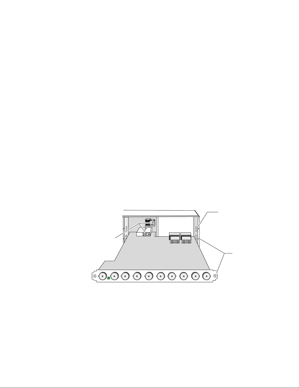
1.
Install the module by inserting it into any rear slot of the frame as
illustrated in Figure 1.
Verify that the module connector seats properly against the midplane.
Secure the module to the rear of the frame with the two screw locks on
either side of the back panel using a crossblade screwdriver.
Figure 1. Installing 2041EDA Module
Alignment post
and receptacle
J10
SIGINJ9 J8 J7 J6 J5 J4 J3 J2
2000 frame (rear view)
Board edge guides
(both sides)
2041
EDA
J1
Screw lock
(both sides)
8032_01
8 2041EDA Instruction Manual
Page 9
Cabling
Inputs
Outputs
Installation
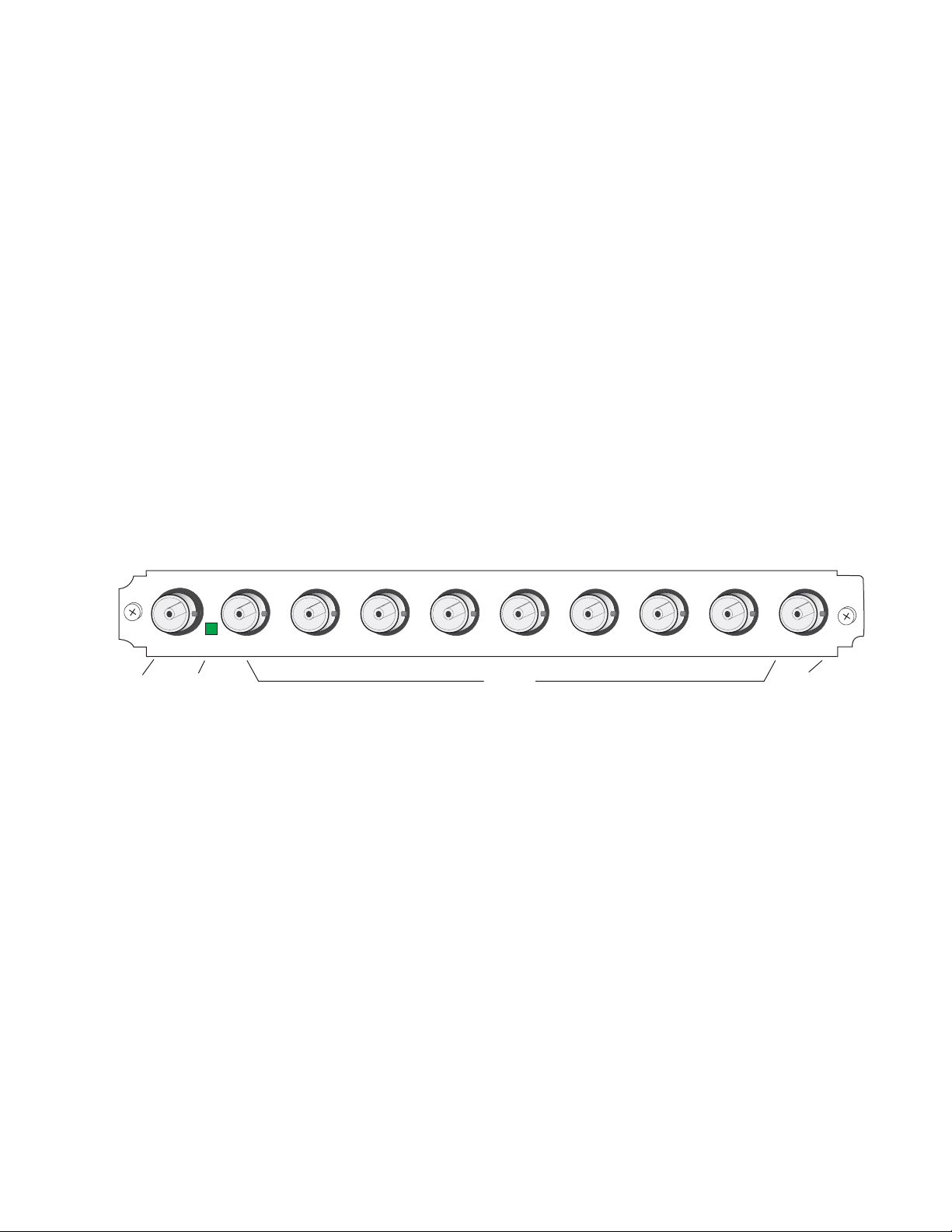
Cabling to the 2041EDA module is done on the BNCs on the rear of the
module. Refer to Figure 2 for a detailed illustration of the rear connections
referenced below.
The 2041EDA will accept any of the video standards listed in the Input
specifications in Table 3 on page 14. Connect a video input to BNC J10.
The 2041EDA outputs conform to the video standards listed in the Output
specifications in Table 3 on page 14.
Connect video destinations to any of the eight outputs at connectors J2 – J9.
Terminate any unused outputs.
In
J10
Video
Input
SIG
Signal Present
LED
Note
Figure 2. 2041EDA Input/Output Connectors
J9 J8 J7 J6 J5 J4 J3 J2 J1
BNC J1 is not used on this module. On earlier versions of the 2041EDA
labeled with part number 671-5248-00, BNC J1 provided an output.
Outputs
Not
Used
2041EDA
8032_02r1
2041EDA Instruction Manual 9
Page 10
Power Up
Power Up
Operation Indicator LEDs
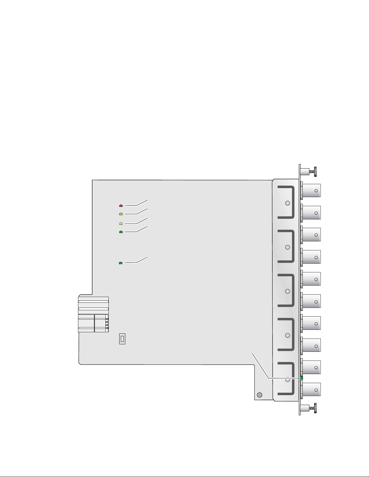
The on-board LED indicators are illustrated in Figure 3. Upon power-up,
the green PWR LED should light and the yellow CONF LED should illuminate for the duration of module initialization.
With a valid input signal connected, the green on-board PWR LED,
SIG_PRES LED and the SIG LED (visible from the rear) should be on. Refer
to Table 1 on page 11 to see a complete list of possible operating conditions
and the resulting indicator status.
Figure 3. LEDs and Configuration Switches
FAULT
COMM
CONF
PWR
SIG_PRES
Fault – (red) off during normal operation
Communication – (yellow)
Configuration – (yellow)
Power – (green) on during normal operation
Remote override – (yellow)
Signal present – (green)
F1
Signal present – (green) on rear connector plate
10 2041EDA Instruction Manual
8032_03
Page 11

A red FAULT LED indicates an error situation and, when noted with the
other indicator LEDs, can indicate a specific problem area. Table 1 describes
signal output and LED indications for the various input/reference combinations.
Table 1. Indicator LEDs and Conditions Indicated
LED Indication Condition
Off Normal operation
FAULT (red)
COMM (yellow)
CONF (yellow)
PWR (green)
SIG_PRES
SIG (rear view)
On continuously Module has detected internal fault
Long flash No input signal
Off No activity on frame communication bus
Long flash Location Command received by the module from a remote control system
Short flash Activity present on the frame communication bus
Off Module is in normal operating mode
On continuously Module is initializing, changing operating modes or updating firmware
Off No power to module or module’s DC/DC converter failed
On continuously Normal operation, module is powered
Off Indicates no signal carrier present
On continuously Indicates signal carrier present
Off Indicates no signal carrier present
On continuously Indicates signal carrier present
Power Up
Table 2 provides the possible input and output conditions that result from
different input signals and conditions.
Table 2. Input and Output Conditions
Input Condition Output Condition
Serial Digital Component (SDI) Serial Digital Component (SDI)
HD Digital Component (SDI) HD Digital Component (SDI)
Other carrier Other carrier
No input Muted
Cable exceeding 200 meters Muted
2041EDA Instruction Manual 11
Page 12

Configuration and Monitoring
Configuration and Monitoring
The 2041EDA has no configuration requirements. There are no local
jumpers or controls on the 2041EDA module.
Remote Monitoring
2041EDA monitoring can be performed remotely using the 2000NET interface (see Figure 4). This section describes the GUI access to the module configuration and monitoring functions. Refer to the 2000NET Network
Interface Module Instruction Manual for information on setting up and
operating the 2000 frame network.
Note
The 2000 modules can be addressed by clicking on a specific module icon
in the frame status display or on a module name or slot number in the link
list on the left.
Figure 4. 2000NET GUI
The Links section lists the frame and its current modules. The selected link's Status
page is first displayed and the sub-list of links for the selection is opened. The sub-list
allows you to select a particular information page for the selected device.
The physical appearance of the menu displays shown in this manual represent the use of a particular platform, browser and version of 2000NET
module software. They are provided for reference only. Displays will differ
depending on the type of platform and browser you are using and the version
of the 2000NET software installed in your system.
Content display section displays the information page
for the selected frame or module (frame slot icons are also
active links).
Refresh button for manual
refresh of page
Online Manual Link
8046-13 r1
12 2041EDA Instruction Manual
Page 13

Module Configuration Displays
The 2000 GUI provides the following links and displays for the 2041EDA
module (Figure 5):
•Module Configuration displays showing slot configuration information (location and user assigned names), and
• Software Update display.
The Module Configuration displays operate in the same manner for all
remote controllable 2000 modules. Refer to the 2000NET manual for more
information on these displays. Some functions listed may not be supported
by a particular module. These will be indicated as not supported.
Figure 5. 2041EDA Display Links
Module Configuration
Displays
Configuration and Monitoring
Software Update
Display
Software Update Displays
The Software Update display allows you to download new software versions for the module. Refer to the 2000NET manual and the Grass Valley
web site at http://www.thomsongrassvalley.com for complete details and
new software versions.
2041EDA Instruction Manual 13
Page 14

Specifications
Specifications
Table 3. 2041EDA Specifications
Parameter Value
Input
Number and type of inputs 1 BNC
Input impedance 75 Ohm
Input signal type Serial digital component conforming to the following formats:
• SMPTE 292M
• SMPTE 259M (143 Mbps, 177 Mbps, 270 Mbps, 360 Mbps)
• EBU 1697
• 4 Mbps to 1.5 Gbps with PN20 pseudonoise sequence, maximum
ratio of 19/1
• SMPTE 310M
• DVB-ASI
Signal level SDI 800 mV p-p ±10% max
Return loss >15 dB 0.004 to 1.5 GHz
Differential mode range <5 V up to 60 Hz
Equalization Auto equalizing:
HD signals up to 90 m of Belden 8281 or 120 m of Belden 1694a
SD signals up to 100 m of Belden 8281 or equivalent
Outputs
Number and type of outputs 8 BNCs
Output impedance 75 Ohm
Signal type Serial digital component conforming to the following formats:
• SMPTE 292M
• SMPTE 259M (143 Mbps, 177 Mbps, 270 Mbps, 360 Mbps)
• EBU 1697
• 4 Mbps to 1.5 Gbps with PN20 pseudonoise sequence, maximum
ratio of 19/1
• SMPTE 310M
• DVB-ASI
Signal level SDI 800 mV p-p ±10%
Return loss >15 dB 0.004 to 1.5 GHz
Error Checking Transparent to embedded EDH
Electrical length 10 ns
Signal polarity Non-inverted
Mute Between 200-300 m of Belden 8281
Rise and fall time 160-270 ps between 20-80%
Power
Input power maximum < 7W
Environmental
Frame temperature range 0 to 45 ° C
Operating humidity range 0 to 90% non condensing
Non-operating temperature -10 to 70 ° C
14 2041EDA Instruction Manual
Page 15

Service
Power-up Diagnostics Failure
Troubleshooting
The 2041EDA modules make extensive use of surface-mount technology
and programmed parts to achieve compact size and adherence to
demanding technical specifications. Circuit modules should not be serviced in the field unless otherwise directed by Customer Service.
If the module has not passed self-diagnostics, do not attempt to troubleshoot. Return the unit to Grass Valley (see Module Repair ).
If your module is not operating correctly, proceed as follows:
Service
•Check frame and module power. If power is not present, check the fuse
on the module as illustrated in Figure 6.
•Check for presence and quality of input signals.
•Verify that source equipment is operating correctly.
•Check cable connections.
Figure 6. Location of Module Fuse
Fuse F1
2A, 125V F
J10
SIGINJ9 J8 J7 J6 J5 J4 J3 J2 J1
2041
EDA
8032_05
Module Repair
If the module is still not operating correctly, replace it with a known good
spare and return the faulty module to a designated Grass Valley repair
depot. Call your Grass Valley representative for depot location.
Refer to Contacting Grass Valley Group at the front of this document for the
Grass Valley Customer Service Information number.
2041EDA Instruction Manual 15
Page 16

Functional Description
Functional Description
A block diagram of the 2041EDA is shown in Figure 7.
Figure 7. 2041EDA Block Diagram
Input
Serial
SD or
HD in
Amplifier
Equalizer
Serial
SD or
HD Out
Input Processing
The wideband serial SD or HD signal enters the module from rear BNC J10
(labeled In) to an input amplifier. It is then equalized for the specified cable
lengths in the equalizer circuit.
Microprocessor
The main functions of the microprocessor include:
•Providing remote control and monitoring capability for the module
Microprocessor
Ethernet
(through ethernet),
Output
Drivers
LEDs
8032_04r1
•Communicating with equalizer IC to monitor signal present status,
•Relaying module status through on-board LEDs, and
•Configuring module components at power up.
16 2041EDA Instruction Manual
Page 17

Output Processing
Driver circuits drive each of the eight serial digital outputs to the rear BNCs
J2 through J9. These outputs are non-inverting and are in-phase with each
other.
Power Supply
Power is fed from +24 V rails of the frame’s switching power supply. Each
stage of the module receives its own, separate, highly regulated and filtered
power source. The power input is protected by a socketed fuse (Figure 6).
Functional Description
2041EDA Instruction Manual 17
Page 18

Functional Description
18 2041EDA Instruction Manual
Page 19

Index
Numerics
2000NET module
B
block diagram
C
cabling
inputs
outputs
circuit descriptions
COMM LED
CONF (configuring) LED
D
documentation online
9
9
E
environmental
equalization
11
7
16
14
13
16
2
11
I
inputs 9
specifications 14
installation 8
L
LEDs 10
M
monitoring
remote
12
N
network 12
O
online documentation 2
outputs 9
specifications 14
P
F
FAQ database
FAULT LED
fault table 11
frame status display 12
frame, 3RU 8
frequently asked questions 2
fuse 15, 17
2
11
G
Grass Valley Group website 2
GUI 12, 13
2041EDA Instruction Manual 19
PWR LED 10, 11
R
repair depot 15
S
SIG LED (rear) 10, 11
SIG_PRES LED 10, 11
software download from web 2
software update 13
specifications 8, 14
Page 20

Index
T
troubleshooting 15
W
web site documentation 2
web site FAQ database 2
web site Grass Valley Group 2
web site software download 2
20 2041EDA Instruction Manual
 Loading...