

Page 1
2040RDA-FR/16FR
FIBER READY DISTRIBUTION AMPLIFIERS
Instruction Manual
Software Version 2.1.1
071836001
APRIL 2010
Page 2

Affiliate with the N.V. KEMA in The Netherlands
CERTIFICATE
Certificate Number: 510040.001
The Quality System of:
Thomson Inc, and it’s wordwide Grass Valley division affiliates DBA
GRASS VALLEY
Headquarters
400 Providence Mine Rd
Nevada City, CA 95959
United States
15655 SW Greystone Ct.
Beaverton, OR 97006
United States
10 Presidential Way
Suite 300
Woburn, MA 01801
United States
Kapittelweg 10
4827 HG Breda
The Nederlands
7140 Baymeadows Way
Ste 101
Jacksonville, FL 32256
United States
2300 So. Decker Lake Blvd.
Salt Lake City, UT 84119
United States
Rue du Clos Courtel
CS 31719
35517 Cesson-Sevigné Cedex
France
1 rue de l’Hautil
Z.I. des Boutries BP 150
78702 Conflans-Sainte
Honorine Cedex
France
Technopole Brest-Iroise
Site de la Pointe du Diable
CS 73808
29238 Brest Cedex 3
France
40 Rue de Bray
2 Rue des Landelles
35510 Cesson Sevigné
France
Spinnereistrasse 5
CH-5300 Turgi
Switzerland
Brunnenweg 9
D-64331 Weiterstadt
Germany
Carl-Benz-Strasse 6-8
67105 Schifferstadt
Germany
Including its implementation, meets the requirements of the standard:
ISO 9001:2008
Scope:
The design, manufacture and support of video and audio hardware and software products and
related systems
.
This Certificate is valid until: June 14, 2012
This Certificate is valid as of: June 14, 2009
Certified for the first time: June 14, 2000
H. Pierre Sallé
President
KEMA-Registered Quality
The method of operation for quality certification is defined in the KEMA General Terms
And Conditions For Quality And Environmental Management Systems Certifications.
Integral publication of this certificate is allowed.
KEMA-Registered Quality, Inc.
4377 County Line Road
Chalfont, PA 18914
Ph: (215)997-4519
Fax: (215)997-3809
CRT 001 073004
ccredited By:
ANAB
A
Page 3

2040RDA-FR/16FR
FIBER READY DISTRIBUTION AMPLIFIERS
Instruction Manual
Software Version 2.1.1
071836001
APRIL 2010
Page 4
Contacting Grass Valley
International
Support Centers
Local Support
Centers
(available
during normal
business hours)
France
24 x 7
Australia and New Zealand: +61 1300 721 495 Central/South America: +55 11 5509 3443
Middle East: +971 4 299 64 40 Near East and Africa: +800 8080 2020 or +33 1 48 25 20 20
Europe
+800 8080 2020 or +33 1 48 25 20 20
Hong Kong, Taiwan, Korea, Macau: +852 2531 3058 Indian Subcontinent: +91 22 24933476
Asia
Southeast Asia/Malaysia: +603 7805 3884 Southeast Asia/Singapore: +65 6379 1313
China: +861 0660 159 450 Japan: +81 3 5484 6868
Belarus, Russia, Tadzikistan, Ukraine, Uzbekistan: +7 095 2580924 225 Switzerland: +41 1 487 80 02
S. Europe/Italy-Roma: +39 06 87 20 35 28 -Milan: +39 02 48 41 46 58 S. Europe/Spain: +34 91 512 03 50
Benelux/Belgium: +32 (0) 2 334 90 30 Benelux/Netherlands: +31 (0) 35 62 38 42 1 N. Europe: +45 45 96 88 70
Germany, Austria, Eastern Europe: +49 6150 104 444 UK, Ireland, Israel: +44 118 923 0499
Copyright © Grass Valley, Inc. All rights reserved.
This product may be covered by one or more U.S. and foreign patents.
United States/Canada
24 x 7
+1 800 547 8949 or +1 530 478 4148
Grass Valley Web Site
The www.grassvalley.com web site offers the following:
Online User Documentation — Current versions of product catalogs, brochures,
data sheets, ordering guides, planning guides, manuals, and release notes
in .pdf format can be downloaded.
FAQ Database — Solutions to problems and troubleshooting efforts can be
found by searching our Frequently Asked Questions (FAQ) database.
Software Downloads — Download software updates, drivers, and patches.
4 2040RDA-FR/16FR — Instruction Manual
Page 5

Contents
Preface. . . . . . . . . . . . . . . . . . . . . . . . . . . . . . . . . . . . . . . . . . . . . . . . . . . . . . . . . . . . . . . . . . . . . 7
2040RDA-FR, 2040RDA-16FR Fiber Ready Distribution Amplifiers. . . 9
About This Manual . . . . . . . . . . . . . . . . . . . . . . . . . . . . . . . . . . . . . . . . . . . . . . . . . . . . . 7
Introduction . . . . . . . . . . . . . . . . . . . . . . . . . . . . . . . . . . . . . . . . . . . . . . . . . . . . . . . . . . . 9
Installation . . . . . . . . . . . . . . . . . . . . . . . . . . . . . . . . . . . . . . . . . . . . . . . . . . . . . . . . . . . 10
Front Module Onboard Jumper Settings . . . . . . . . . . . . . . . . . . . . . . . . . . . . . . . . 10
Factory Defaults . . . . . . . . . . . . . . . . . . . . . . . . . . . . . . . . . . . . . . . . . . . . . . . . . . . 10
Remote Control Jumper . . . . . . . . . . . . . . . . . . . . . . . . . . . . . . . . . . . . . . . . . . . . 10
Input/Output Select Jumpers . . . . . . . . . . . . . . . . . . . . . . . . . . . . . . . . . . . . . . . 12
Auto/Bypass Jumper . . . . . . . . . . . . . . . . . . . . . . . . . . . . . . . . . . . . . . . . . . . . . . 12
Module Placement in the 2000 Frame. . . . . . . . . . . . . . . . . . . . . . . . . . . . . . . . . . . 13
Cabling . . . . . . . . . . . . . . . . . . . . . . . . . . . . . . . . . . . . . . . . . . . . . . . . . . . . . . . . . . . . 18
2040RDA-FR or 2040RDA-16FR with No SFP Option . . . . . . . . . . . . . . . . . . . 18
2040RDA-FR or 2040RDA-16FR with Dual Optical Transmitter . . . . . . . . . . 20
2040RDA-FR or 2040RDA-16FR with Optical Transceiver . . . . . . . . . . . . . . . 21
Power Up . . . . . . . . . . . . . . . . . . . . . . . . . . . . . . . . . . . . . . . . . . . . . . . . . . . . . . . . . . . . 22
Configuration and Adjustments . . . . . . . . . . . . . . . . . . . . . . . . . . . . . . . . . . . . . . . . . 24
Configuration Summary. . . . . . . . . . . . . . . . . . . . . . . . . . . . . . . . . . . . . . . . . . . . . . 24
Newton Control Panel Configuration . . . . . . . . . . . . . . . . . . . . . . . . . . . . . . . . . . 25
Web Browser Interface . . . . . . . . . . . . . . . . . . . . . . . . . . . . . . . . . . . . . . . . . . . . . . . 26
2040RDA-16FR Links and Web Pages . . . . . . . . . . . . . . . . . . . . . . . . . . . . . . . . . . 28
Status Web Page. . . . . . . . . . . . . . . . . . . . . . . . . . . . . . . . . . . . . . . . . . . . . . . . . . . 29
Settings Web Page . . . . . . . . . . . . . . . . . . . . . . . . . . . . . . . . . . . . . . . . . . . . . . . . . 31
Recall Factory Defaults Web Page. . . . . . . . . . . . . . . . . . . . . . . . . . . . . . . . . . . . 35
Slot Config Web Page . . . . . . . . . . . . . . . . . . . . . . . . . . . . . . . . . . . . . . . . . . . . . . 36
Slot Identification. . . . . . . . . . . . . . . . . . . . . . . . . . . . . . . . . . . . . . . . . . . . . . . . . . 37
Locate Module . . . . . . . . . . . . . . . . . . . . . . . . . . . . . . . . . . . . . . . . . . . . . . . . . . . . 37
Slot Memory . . . . . . . . . . . . . . . . . . . . . . . . . . . . . . . . . . . . . . . . . . . . . . . . . . . . . . 37
Frame Health Reports Link . . . . . . . . . . . . . . . . . . . . . . . . . . . . . . . . . . . . . . . . . 37
LED Reports Link. . . . . . . . . . . . . . . . . . . . . . . . . . . . . . . . . . . . . . . . . . . . . . . . . . 38
SNMP Trap Reports Link . . . . . . . . . . . . . . . . . . . . . . . . . . . . . . . . . . . . . . . . . . . 38
Rear Module Web Page. . . . . . . . . . . . . . . . . . . . . . . . . . . . . . . . . . . . . . . . . . . . . 39
Software Updating . . . . . . . . . . . . . . . . . . . . . . . . . . . . . . . . . . . . . . . . . . . . . . . . . . . . 40
Equipment Required. . . . . . . . . . . . . . . . . . . . . . . . . . . . . . . . . . . . . . . . . . . . . . . . . 40
Acquiring Software Updates . . . . . . . . . . . . . . . . . . . . . . . . . . . . . . . . . . . . . . . . . . 40
Specifications . . . . . . . . . . . . . . . . . . . . . . . . . . . . . . . . . . . . . . . . . . . . . . . . . . . . . . . . . 41
Service. . . . . . . . . . . . . . . . . . . . . . . . . . . . . . . . . . . . . . . . . . . . . . . . . . . . . . . . . . . . . . . 44
Power-up Diagnostics Failure . . . . . . . . . . . . . . . . . . . . . . . . . . . . . . . . . . . . . . . . . 44
Troubleshooting. . . . . . . . . . . . . . . . . . . . . . . . . . . . . . . . . . . . . . . . . . . . . . . . . . . . . 44
Module Repair . . . . . . . . . . . . . . . . . . . . . . . . . . . . . . . . . . . . . . . . . . . . . . . . . . . . . . 45
Functional Description . . . . . . . . . . . . . . . . . . . . . . . . . . . . . . . . . . . . . . . . . . . . . . . . . 45
Electrical Input and Output Processing. . . . . . . . . . . . . . . . . . . . . . . . . . . . . . . . . 46
Optical Input and Output Processing. . . . . . . . . . . . . . . . . . . . . . . . . . . . . . . . . . . 47
2040RDA-FR/16FR — Instruction Manual 5
Page 6

Contents
Microprocessor and Input Selector . . . . . . . . . . . . . . . . . . . . . . . . . . . . . . . . . . . . 47
Index. . . . . . . . . . . . . . . . . . . . . . . . . . . . . . . . . . . . . . . . . . . . . . . . . . . . . . . . . . . . . . . . . . . . . . 49
6 2040RDA-FR/16FR — Instruction Manual
Page 7

Preface
About This Manual
This manual describes the features of a specific 2000 Series module in the
Kameleon Media Processing System. As part of this module family, it is
subject to Safety and Regulatory Compliance described in the 2000 Series
frame and power supply documentation (see the Kameleon 2000 Series
Frames Instruction Manual).
All Modular product manuals can be found on-line in PDF format at this
link:
www.grassvalley.com/docs/modular
2040RDA-FR/16FR — Instruction Manual 7
Page 8

Preface
8 2040RDA-FR/16FR — Instruction Manual
Page 9

2040RDA-FR, 2040RDA-16FR Fiber Ready Distribution Amplifiers
Introduction
The 2040RDA-FR and 2040RDA-16FR Fiber Ready Distribution Amplifiers
provides one electrical input by either eight or sixteen non-inverting elec
trical outputs for distributing SD, HD, and DVB-ASI signals. The module
also handles optical/electrical fiber conversion with optional low power
single mode SFP (Small-form Factor Pluggable)/LC 1310nm optical trans
ceiver (input/output) or dual transmitter submodules. This provides both
optical inputs and outputs depending on the type of submodule installed
in the rear module.
Auto-detection and reclocking capability are available at all SD (standard
definition) and HD (high definition) data rates. The reclocking circuit can
be bypassed to distribute signals down to 4 Mbps.
-
-
The 2040RDA-FR and 2040RDA-16FR features include:
• 2040RDA-FR: Eight BNC electrical outputs, one BNC electrical input, or
• 2040RDA-16FR: Sixteen BNC electrical outputs, one BNC electrical
input,
• Single mode fiber optic submodule option for dual transmitter (2 outputs) or transceiver (1 input/1 output),
• Module and SFP submodule are both hot-swappable,
• Automatic data rate detection,
• Reclocks at 143 Mb/s, 177 Mb/s, 270 Mb/s, 360 Mb/s, 540 Mb/s, or
1485 Mb/s,
• Distributes transport streams in bypass mode,
• Auto-adjust rise/fall times to meet either the SD or HD standard, and
• Supports networked control and monitoring in frames with 2000NET
module.
2040RDA-FR/16FR — Instruction Manual 9
Page 10

Installation
Installation
Front Module Onboard Jumper Settings
Installation of a 2040RDA-FR or 2040RDA-16FR module set is a process of:
• Setting on-board jumpers on the front media module for modules not
using remote control or to set module defaults,
• Placing the 2040RDA-FR-R or 2040RDA-16FR-R rear module in a frame
slot,
• Installing the fiber optic SFP submodule (optional),
• Placing the front media module in the corresponding front slot, and
• Cabling signal ports.
The 2040RDA-FR and 2040RDA-16FR modules have four onboard jumpers
that can be configured for determining the following functions:
• Jumper JP1 – sets control mode for Local only or Remote and Local.
• Jumper JP2 and JP3 – set the input format for the module and/or optic
output enables.
• Jumper JP4 – sets module for bypass or reclocking function.
Factory Defaults
The local settings made on J2, J3, and J4 are the defaults for the module.
Changing any local jumper setting while the module is powered up or
removed and plugged back into the frame will immediately reset the
module to the current local jumper settings. This will also occur when
removing or installing an optic submodule.
Selecting the Recall Fact. Defaults button on the Recall Factory Defaults web
page (
page 35) will return the module to these local settings.
Remote Control Jumper
When the jumper is placed across pins 1 and 2 of jumper block JP1, module
settings are changed from the on-board jumpers only; remote control is
locked out. To have both Local and Remote access, set the jumper across
pins 2 and 3.
10 2040RDA-FR/16FR — Instruction Manual
Page 11
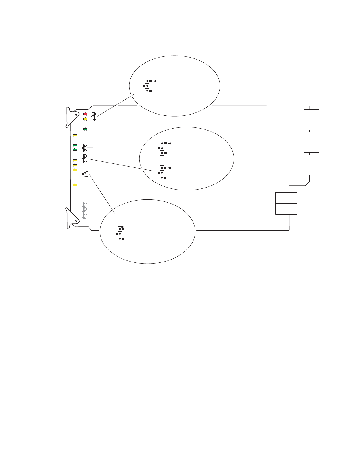
Figure 1. Module Configuration Jumpers
8269_06r1
Jumper across pins 1–2
to lock out remote control.
Jumper across pins 2–3
to enable remote and
local control.
LOC
LOC&
REM
Jumper across pins 1–2
selects automatic reclocking.
Jumper across pins 2–3
bypasses reclocking function.
Remote Control Lockout
Auto/Bypass Reclocking
JP1
AUTO
BPSS
JP4
Set JP2 and JP3 for input
according to module
silkscreen.
1
0
Input Select
JP2
1
0
JP3
Installation
2040RDA-FR/16FR — Instruction Manual 11
Page 12
Installation
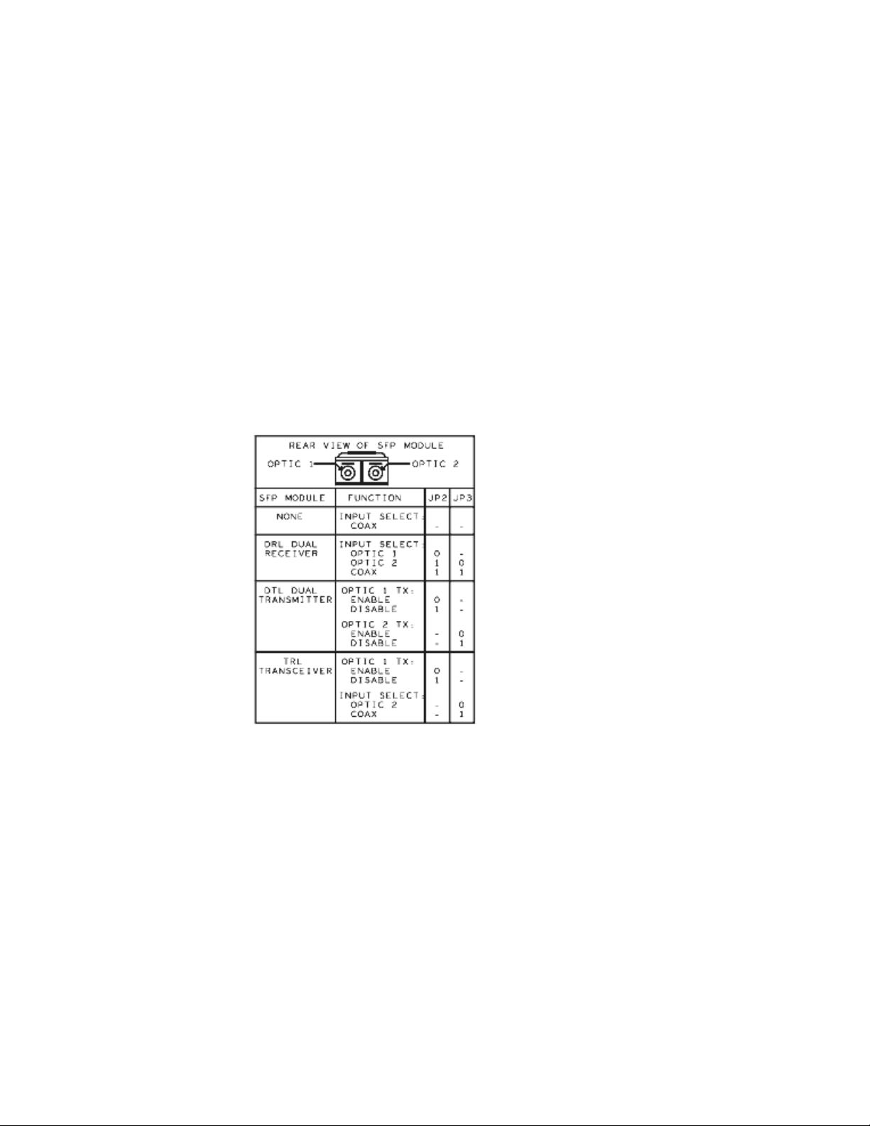
Input/Output Select Jumpers
Set jumpers JP2 and JP3 to 0 (pins 2-3) or 1 (pins 1-2) to select the
input/output type and/or optic output enable according to the silkscreen
on the front module shown in
Note The silkscreen on the module reflects an older version set of SFP submod-
ules. The older version submodules may still be used, but newer submodules, SFP-13103G-M1TRX (DTL Dual Transmitter) and SFP-13103G-M1TRX
(TRL Transceiver) will only work with the newer version software.
These jumper settings can be overridden by remote control. When this condition occurs, the front edge yellow REM OVR LED will light (refer to
Ta bl e 1 on page 23).
Note The Dual Receiver function is not used at this time.
Figure 2. 2040RDA-FR and 2040RDA-16FR Front Module Silkscreen
Figure 2.
Auto/Bypass Jumper
In Local mode, the module will operate in Auto or Bypass mode.
When set to Auto mode, the module will automatically reclock the incoming
signal to 143 Mb/s, 270 Mb/s, 360 Mb/s, 540 Mb/s, or 1.485 Gb/s rates
(ASI 270 signals). If the input signal cannot lock to one of these rates, the
reclocking will be bypassed automatically.
When set to Bypass mode, the reclocking will be bypassed completely.
Set jumper JP4 for auto-reclocking (AUTO pins 1-2) or to bypass reclocking
(BPSS pins 2-3). This jumper setting can be overridden by remote control.
When the module is in Bypass, the front edge LD LED will be off (refer to
Ta bl e 1 on page 23).
12 2040RDA-FR/16FR — Instruction Manual
Page 13
Module Placement in the 2000 Frame
J6J7J8J9J10
2040RDA
-FR
J5 J3J4 J2 J1
J6J7J8J9J10
2040RDA
-FR
J5 J3J4 J2 J1
J6J7J8J9J10
2040RDA
-FR
J5 J3J4 J2 J1
J6J7J8J9J10
2040RDA
-FR
J5 J3J4 J2 J1
J6J7J8J9J10
2040RDA
-FR
J5 J3J4 J2 J1
J6J7J8J9J10
2040RDA
-FR
J5 J3J4 J2 J1
J6J7J8J9J10
2040RDA
-FR
J5 J3J4 J2 J1
J6J7J8J9J10
2040RDA
-FR
J5 J3J4 J2 J1
J6J7J8J9J10
2040RDA
-FR
J5 J3J4 J2 J1
J6J7J8J9J10
2040RDA
-FR
J5 J3J4 J2 J1
J6J7J8J9J10
2040RDA
-FR
J5 J3J4 J2 J1
J6J7J8J9J10
2040RDA
-FR
J5 J3J4 J2 J1
Mid-frame motherboard
with power and
communication buses
Rear media module slots 1– 6Rear media module slots 7– 12
8360_02
There are twelve slot locations in both the front and rear of a Kameleon
RU frame to accommodate 2000 Series modules. The 2040RDA-FR and
3
2040RDA-16FR modules set consists of a front media module and a rear
module for the 2040RDA-FR or a dual height rear module for the
2040DRA-16FR that requires two module slots.
Each 2040RDA-FR or 2040RDA-16FR front media module plugs into the
front of the 2000 frame mid-plane. The rear module plugs into the corre
sponding rear slot to provide the input and output interface connectors.
Stacked BNCs on the 2040RDA-16FR passive rear module require two rear
slots. The fiber optic SFP submodule option installs in the connector cage
on the top right of the rear module.
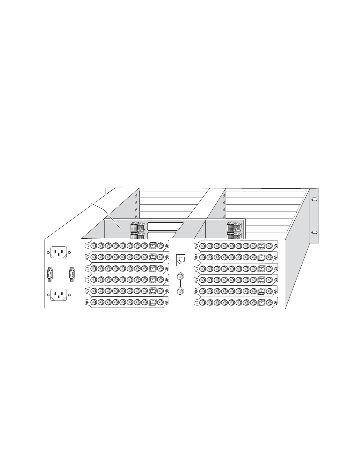
A 3 RU 2000T3 frame fully stuffed with 2040RDA-FR front and rear
modules will accommodate up to twelve module sets as shown in
A 1 RU 2000T1 frame will accommodate up to 4 module sets.
Figure 3. 2040RDA-FR 3 RU Frame, Rear View
Installation
-
Figure 3.
2040RDA-FR/16FR — Instruction Manual 13
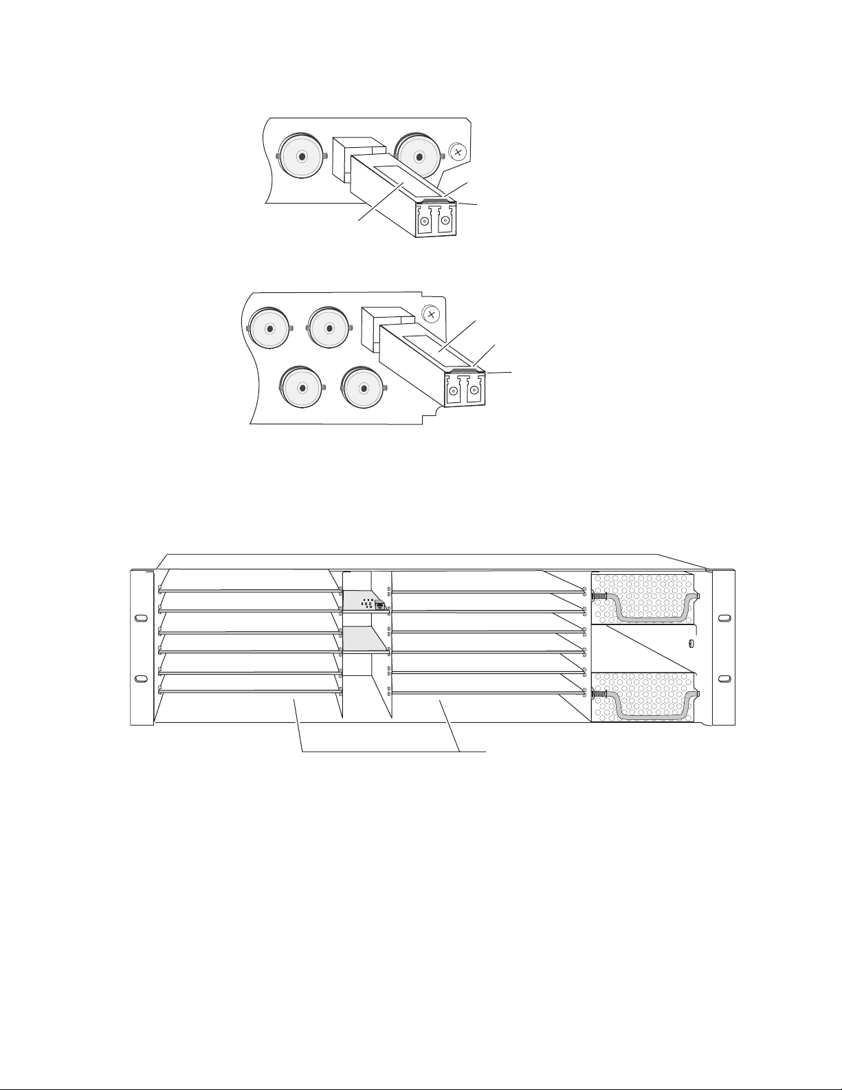
A 3 RU 2000T3 frame fully stuffed with 2040RDA-16FR front and rear
modules will accommodate up to six module sets as shown in
Figure 4. A
1 RU 2000T1 frame will accommodate up to 2 module sets.
Page 14

Installation
Mid-frame motherboard
with power and
communication buses
Use rear media module slots 1, 3, and 5Use rear media module slots 7, 9, and 11
8269_04
Slot 5
Slot 3
Slot 7
Slot 9
Slot 11
Slot 1
Alignment post
and receptacle
Screw locks
(both sides)
8360_11
2000 frame (rear view)
Board edge guides
(both sides)
2040RDA-FR-R Passive Rear Module
Fiber optic
connector cage
Input
Figure 4. 2040RDA-16FR 3 RU Frame, Rear View
The 2040RDA-FR and 2040RDA-16FR front and rear modules and fiber
optic submodules can be plugged in and removed from a Kameleon 2000
Series frame with power on. When power is applied to the module, LED
indicators reflect the initialization process (see
Power Up on page 22).
To install a 2040RDA-FR module set in the frame:
1. Locate a vacant slot in slot 1-12 in the rear of the 1 RU or 3 RU frame
(3 RU frame shown in Figure 3).
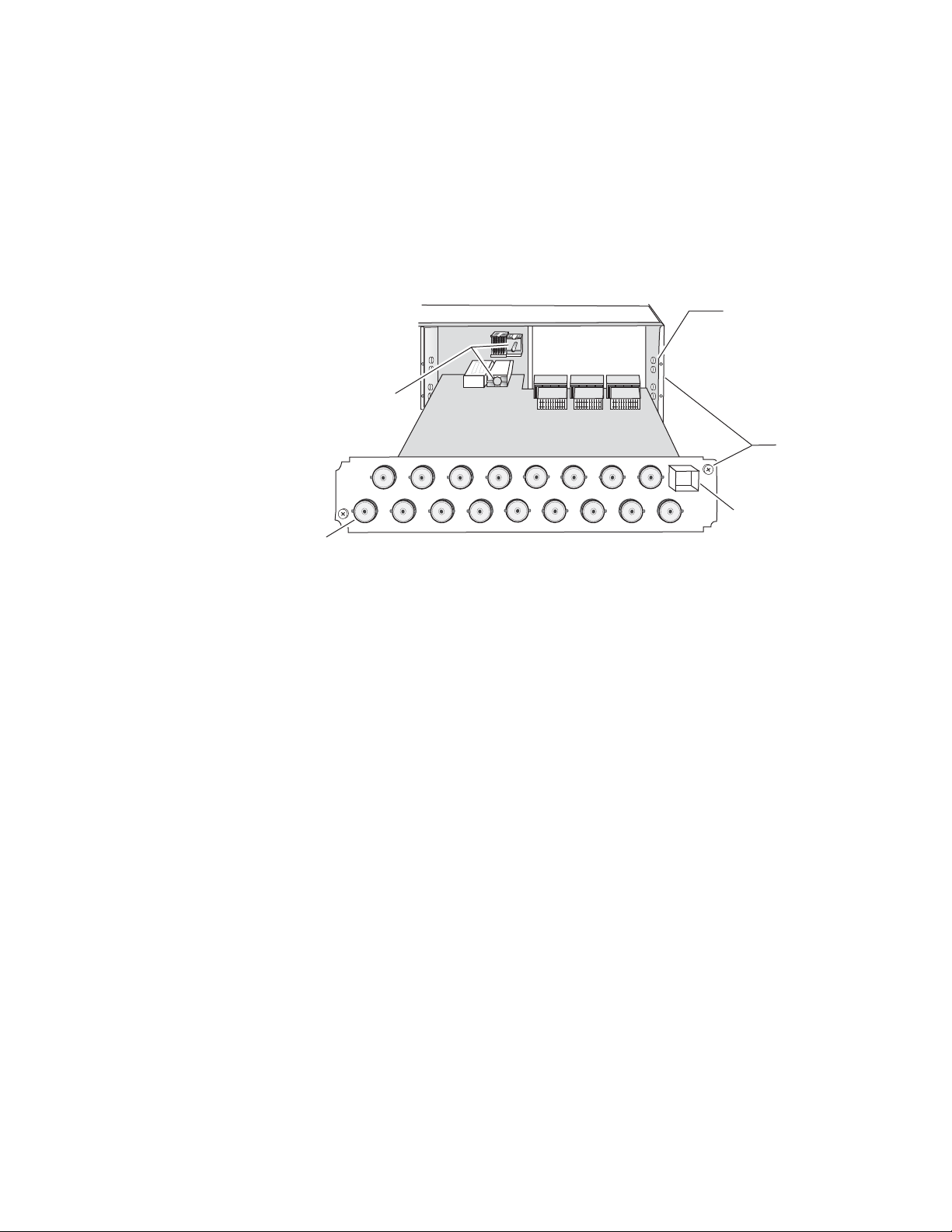
2. Insert the rear module into a vacant rear slot in the frame as illustrated
in Figure 5.
Figure 5. Installing 2040RDA-FR Rear Module
14 2040RDA-FR/16FR — Instruction Manual
Page 15
Installation
To install a 2040RDA-16FR module set in the frame:
1. Locate a vacant slot in slot 1, 3, 5, 7, 9, or 11 of the rear of the 3 RU frame
(Figure 4). The rear module uses two slots.
2. Insert the rear module into vacant rear slot 1, 3, 5, 7, 9, or 11 of the frame
as illustrated in Figure 6.
Figure 6. Installing 2040RDA-16FR Rear Module
2000 frame (rear view)
Alignment post
and receptacle
Board edge guides
(both sides)
Screw locks
(both sides)
Input
Fiber optic
connector cage
2040RDA-16FR-R Passive Rear Module
8269_03
To continue installation of 2040RDA-FR and 2040RDA-16FR modules set in
the frame:
1. Verify that the module connector seats properly against the midplane.
2. Using a crossblade screwdriver, tighten the two screw locks to secure
the module in the frame.
3. To install the optional SFP submodule in the 2040RDA-FR, refer to
Figure 7. The SFP submodule is hot-pluggable and may be installed or
removed with power applied to the module.
4. To install the optional SFP submodule in the 2040RDA-16FR, refer to
Figure 8. The SFP submodule is hot-pluggable and may be installed or
removed with power applied to the module.
The module type is identified by name on the label or can be identified
by the direction of the two arrow indicators on the label.
Note Installing or removing the optical submodule while the module is powered up
will reset the module to a default state—that of the jumper settings currently
set for JP2, JP3, and JP4 (see Factory Defaults on page 10).
5. With the handle in the up position, slide the metal casing, label side up,
into the cage connector on the top right of the rear module.
Note When installed properly, the front end of the submodule will line up with the
BNCs. Do not try to force it in further.
2040RDA-FR/16FR — Instruction Manual 15
Page 16
Installation
Figure 7. Installing SFP Submodule on 2040RDA-FR
2040RDA
-FR
J3
Label
Arrow Indicators
Handle in
up position
8360_09
Figure 8. Installing SFP Submodule on 2040RDA-16FR
Label
Arrow Indicators
Handle in
up position
8269_11
6. For the 2040RDA-FR locate the front slot 1-12 in the frame
corresponding to the rear module circuit board. The 3 RU frame front
view is illustrated in Figure 9.
Figure 9. 2000 Series 3 RU Frame, 2040RDA-FR Frame Slots
(1)
(2)
(3)
(4)
(5)
(6)
(7)
(8)
(9)
(10)
(11)
(12)
Install Front Media modules
into slots 1-12
7. For the 2040RDA-16FR locate the front slot 1, 3, 5, 7, 9, or 11 in the frame
corresponding to the rear module circuit board. The 3 RU frame front
view is illustrated in Figure 10. Module slots where the 2040RDA-16FR
should be installed for a fully stuffed 2000 frame are highlighted in
gray.
Note 2040RDA-16FR modules are not limited to these slots. The dual height rear
and corresponding front module can be placed in any location as long as
there is enough space.
8360_12
16 2040RDA-FR/16FR — Instruction Manual
Page 17

Installation
(2)
(3)
(4)
(5)
(6)
(7)
(8)
(9)
(10)
(11)
(12)
(1)
Install Front Media modules
into slots 1, 3, 5, 7, 9, and 11.
8269_19
2040RDA-16FR
Alignment post and receptacle
8269-10
2000 Frame (front view)
Board edge
guides
Board edge
guides
Figure 10. 2000 Series 3 RU Frame, Front Slots
8. With the component side up, insert the front media module in the
corresponding front slot (see Figure 11).
9. Verify that the module connector seats properly against the midplane
and rear module connector.
10. Press firmly on both ejector tabs to seat the module.
Figure 11. Installing Front Media Module
2040RDA-FR/16FR — Instruction Manual 17
Page 18

Installation
J6J7J8
J9
2040
RDA-16
J5 J3J4 J2 J1
J15J16J17
Input
J14 J12J13 J11 J10
SFP Submodule
connector cage
8269_02
Outputs J1 – J8
Outputs J9 – J16
Cabling
All cabling to the 2040RDA-FR or 2040RDA-16FR module sets is done on
the corresponding Single Height 2040RDA-FR or Dual Height
2040RDA-16FR rear module at the back of the 2000 frame.
Cabling of the rear module depends on what SFP option is installed as follows:
• 2040RDA-FR or 2040RDA-16FR with no SFP Optical submodule option
(electrical only) (page 18)
• 2040RDA-FR or 2040RDA-16FR with SFP-13103G-M1DTX (Dual
Optical Transmitter) option (page 20)
• 2040RDA-FR or 2040RDA-16FR with SFP-13103G-M1TRX (Optical
Transceiver) option (page 21)
2040RDA-FR or 2040RDA-16FR with No SFP Option
The 2040RDA-FR or 2040RDA-16FR can input one electrical SD/HD/ASI
input with either eight or sixteen electrical outputs. On-board jumpers JP2
and JP3 on the circuit board have no effect and can be set for any configu
ration. Refer to Figure 12 for an illustration of the input and output BNCs
for 2040RDA-FR or refer to Figure 13 for an illustration of the input and
output BNCs for 2040RDA-16FR.
-
Input
Figure 12. 2040RDA-FR Rear Module Input/Output Connectors
Outputs BNC J1, J3-J9
J6J7J8J9J10
Figure 13. 2040RDA-16FR Rear Module Input/Output Connectors
J5 J3J4 J2 J1
SFP Submodule
connector cage
2040RDA
-FR
8360_01
18 2040RDA-FR/16FR — Instruction Manual
Page 19

Installation
Electrical Input
Connect an electrical SD, HD, or ASI video input to BNC J10 on the
2040RDA-FR or BNC J17 on the 2040RDA-16FR. The 2040RDA-FR and
2040RDA-16FR will accept any of the serial digital component video
signals conforming to the following formats:
• SMPTE 259M (143 Mb/s, 177 Mb/s, 270 Mb/s, and 360 Mb/s)
• SMPTE 292M (1.485 and 1.485/1.001 Gb/s)
• SMPTE 344M (540 Mb/s)
• 4 Mbps to 1.5 Gb/s
• SMPTE 310M (MPEG up to 38.78 M/bps)
•DVB-ASI
Electrical Outputs
On the 2040RDA-FR the input signal is distributed to 8 output BNCs.
Connect video output devices to outputs J1 and J3 through J9 provided on
the 2040RDA-FR rear module (
Figure 12 on page 18).
On the 2040RDA-16FR the input signal is distributed to 16 output BNCs.
Connect video output devices to outputs J1 through J8 and J9 through J16
provided on the 2040RDA-16FR rear module (
Figure 13 on page 18).
2040RDA-FR/16FR — Instruction Manual 19
Page 20

Installation
2040RDA-FR or 2040RDA-16FR with Dual Optical Transmitter
With the Dual Optical Transmitter installed the module can operate in the
following modes:
• Electrical input to eight electrical outputs and two optical outputs on
the 2040RDA-FR, or
• Electrical input to sixteen electrical outputs and two optical outputs on
the 2040RDA-16FR.
Electrical Input
Connect an SD, HD, or ASI video input to BNC J10 on 2040RDA-FR or BNC
J17 on 2040RDA-16FR as described in
Electrical and Optical Outputs
The input signal is distributed to eight or sixteen electrical output BNCs.
Connect video output devices to outputs J1 and J3 through J9 provided on
the 2040RDA-FR (
provided on the 2040RDA-16FR rear module (Figure 13 on page 18).
Figure 12 on page 18) or J1 through J8 and J9 through J16
Electrical Input on page 19.
The output signal can also be accessed from both optical outputs from the
SFP submodule, Optic 1 (left) and Optic 2 (right), shown in
on-board jumpers JP2 and JP3 to enable or disable one or both of the optical
outputs as described in
submodule handle in the up position, connect optical cables to one or both
outputs.
Figure 14. Dual Transmitter Optical Outputs
Optic 1 (output) Optic 2 (output)
Input/Output Select Jumpers on page 12. With the
8269_13
Figure 14. Set
20 2040RDA-FR/16FR — Instruction Manual
Page 21

2040RDA-FR or 2040RDA-16FR with Optical Transceiver
With the Optical Transceiver SFP option installed the module supports the
following modes:
• Electrical input to eight or sixteen electrical outputs and two optical
outputs, or
• Optical input to eight or sixteen electrical outputs and one optical
output.
Electrical or Optical Input
To use the electrical input, connect an SD, HD, or ASI video input to BNC
J10 on the 2040RDA-FR or BNC J17 on the 2040RDA-16FR as described in
Electrical Input on page 19. Set on-board jumper JP3 to the Coax input as
described in Input/Output Select Jumpers on page 12.
For an optical input, connect the fiber cable to the Optic 2 input (right), as
shown in
described in Input/Output Select Jumpers on page 12.
Figure 15. Set on-board jumper JP3 to enable the optic input as
Installation
Electrical and Optical Outputs
The input signal is distributed to eight or sixteen electrical output BNCs.
Connect video output devices to outputs J1 and J3 through J9 provided on
the 2040RDA-FR rear module (
J9 through J16 provided on the 2040RDA-16FR rear module (Figure 13 on
page 18).
The output signal can also be accessed from the Optic 1 (left) connector
shown in
as described in Input/Output Select Jumpers on page 12. With the submodule
handle in the up position, connect an optical cable to this output.
Figure 15. Dual Transceiver Optical Input and Output
Optic 1 (output) Optic 2 (input)
Figure 15. Enable or disable this output with on-board jumper JP2
8269_14
Figure 12 on page 18) or J1 through J8 and
2040RDA-FR/16FR — Instruction Manual 21
Page 22

Power Up
8269_07
REM OVR CD LD SFP_INSTMODE
FAULT
COMM PWR
FAULT (red)
COMM (yellow)
PWR (green)
REM OVR (yellow)
CD – Carrier Detected (green)
LD – Reclocked Locked (green)
Mode LEDs (yellow)
see table in text
SFP_INST – optic present (yellow)
MODE LED 1
MODE LED 2
MODE LED 3
Power Up
The front LED indicators are illustrated in Figure 16. Upon power-up, the
green PWR LED should light.
Refer to Ta bl e 1 on page 21 to see a complete list of possible operating conditions and the resulting indicator status.
Figure 16. LEDs and Configuration Switches
22 2040RDA-FR/16FR — Instruction Manual
Page 23

A red FAULT LED indicates an error situation and, when noted with the
other indicator LEDs, can indicate a specific problem area.
signal output and LED indications for the various input combinations and
user settings.
Table 1. Indicator LEDs and Conditions Indicated
LED Indication Condition
FAULT
(red)
COMM
(yellow)
PWR
(green)
REM OVR
(yellow)
CD
(green)
LD
(green)
MODE
(yellow)
SFP_INST
1
These LEDs are green on some earlier modules.
1
(yellow)
On continuously
Long flash
3 Short Flashes Location Command received by the module from a remote control system.
Short flash Activity present on the frame communication bus.
On continuously Normal operation, module is powered.
See Tabl e 2
Power Up
Tab le 1 describes
Off Normal operation.
Module has detected an Optic 1 or Optic 2 internal fault from the submodule or a write failure
has occurred on the front module.
No input is detected for the input or the input does not match the format selected manually, no
rear module is present, or the wrong rear module is present.
Off No activity on frame communication bus.
Off No power to module, fuse blown, or module’s DC/DC converter failed.
On Remote control is overriding on-board jumper settings.
Off Module is operating according to on-board jumper settings.
On Carrier is detected for the selected input to the module.
Off No carrier is detected for the selected input to the module or input signal is missing.
On
Off Module is in bypass mode or not locking to valid frequency or input signal is missing.
On Indicates SFP submodule option installed in rear module.
Off Indicates no SFP submodule option installed in rear module.
Selected input carrier is locked to a valid frequency for the module (143M, 177M, 270M,
360M, 540M, or 1485M).
LED On/Off states indicate auto-reclocking signal rate detected by module or reclock rate manually selected on web page.
Ta bl e 2 gives the reclock rates reported by the sequence of the three MODE
LEDs on the front of the module. This information is also silkscreened on
the circuit board. The LED on/off states reflect the auto-reclocking signal
rate detected by module or the reclock rate manually selected on web page.
Table 2. Reclock Mode Table
Reclock Rate
No reclock Off Off Off
143M Off Off On
177M Off On Off
270M Off On On
360M On Off Off
540M On Off On
1.5 G On On On
Mode LED 1
(DS4)
Mode LED 2
(DS5)
Mode LED 3
(DS6)
2040RDA-FR/16FR — Instruction Manual 23
Page 24

Configuration and Adjustments
Configuration and Adjustments
Configuration and monitoring can be performed using local jumper controls, a web browser GUI interface, or a networked Newton Control Panel.
This section provides an overview of each of these controls along with the
configuration parameters available with each type of control device.
Configuration Summary
The configuration parameters and monitoring functions available with the
local on-board jumpers, web browser interface, and the Newton Control
Panel are summarized in
and resolution are provided for each function.
Table 3. Summary of 2040RDA-FR and 2040RDA-16FR Configuration Functions
Ta bl e 3. The parameter defaults, choices, ranges,
Function
Type
Mode
Optic 1 Tx
(Tx-Tx SFP
installed)
Optic 2 Tx
(Tx-Tx SFP
installed)
Optic 1 Tx
(Tx-Rx SFP
installed)
Select Input
(Tx-Rx SFP
installed)
Defaults
Current JP4
jumper setting
Factory = Auto
Current JP2
jumper setting
Factory = Disable
Current JP3
jumper setting
Factory = Disable
Current JP2
jumper setting
Factory = Disable
Current JP3
jumper setting
Factory = Coax
Range/Choices
Resolution
Auto ASI
Auto 177M
Bypass
Reclk 143M
Reclk 177M
Reclk 270M
Reclk 360M
Reclk 540M
Reclk 1485M
Enable or Disable
Enable or Disable
Enable or Disable
Optic 2 or Coax
Web Page/
Function Name
Settings/
Mode Pulldown
Settings/
Optic 1 TX pulldown
Settings/
Optic 2 TX pulldown
Settings/
Optic Tx 1 pulldown
Settings/
Input pulldown
On-Board Jumper
Setting
JP4 pins 1&2=AUTO
JP4 pins 2&3=BYPASS
SFP-13103G-M1DTX
JP2: 0 = Optic 1 Tx Enable
JP2: 1 = Optic 1 Tx Disable
JP3: N/A
SFP-13103G-M1DTX
JP2: N/A
JP3: 0 = Optic 2 Tx Enable
JP3: 1 = Optic 2 Tx Disable
SFP-13103G-M1TRX
JP2: 0 = Optic 1 Tx Enable
JP2: 1 = Optic 1 Tx Disable
JP3: N/A
SFP-13103G-M1TRX
JP2: N/A
JP3: 0 = Optic 2 Input Select
JP3: 1 = Coax Input Select
Newton
Control
Panel
Mode
OptTx1En
OptTx2En
OptTx1Out
InSelTR
24 2040RDA-FR/16FR — Instruction Manual
Page 25

Newton Control Panel Configuration
A Newton Control Panel (hard or soft version) can be interfaced to the
Kameleon 2000 Series frame over the local network. Control panel access
offers the following considerations for module configuration and moni
toring:
• Ability to separate system level tasks from operation ones, minimizing
the potential for on-air mistakes.
• Ability to group modular products—regardless of their physical locations—into logical groups (channels) that you can easily manipulate
with user-configured knobs.
• Update software for applicable modules and assign frame and panel IP
addresses with the NetConfig Networking application.
• Recommended for real-time control of module configuration parameters, providing the fastest response time.
Note Not all module functions are available with the control panel, such as factory
default recalls. The available control panel controls for the module are listed
in Table 3 on page 24.
Configuration and Adjustments
-
An example of the Newton Configurator is shown in Figure 17.
Figure 17. Newton Configurator Example
Refer to the documentation that accompanies the Newton Modular Control
System for installation, configuration, and operation information.
2040RDA-FR/16FR — Instruction Manual 25
Page 26

Configuration and Adjustments
Web Browser Interface
The web browser interface provides a graphical representation of module
configuration and monitoring.
Use of the web interface offers the following considerations:
• Provides complete access to all module status and configuration func-
• Web access will require some normal network time delays for pro-
tions, including naming of inputs and outputs, factory parameter and
name default recalls, E-MEM functions, slot configuration, and SNMP
monitoring controls.
cessing of information.
• Configuration parameter changes may require pressing the
or
Enter, upload processing time, and a manual screen refresh to become
effective.
• Web interface recommended for setting up module signal and slot
names, E-MEMs, and reporting status for SNMP and monitoring.
Refer to the Frame Status page shown in Figure 18 on page 27. The Kameleon and 2000 modules can be addressed by clicking either on a specific
module icon in the frame status display or on a module name or slot
number in the link list on the left.
Note The physical appearance of the menu displays on the web pages shown in
this manual represent the use of a particular platform, browser and version
of 2000NET module software. They are provided for reference only. Displays
will differ depending on the type of platform and browse
the version of the 2000NET software installed in your system. This manual
reflects 2000NET software version 4.0.2 required for this release.
r you are using and
Apply button
26 2040RDA-FR/16FR — Instruction Manual
Page 27

Figure 18. 2000NET GUI
8269_20r2
The Links section lists the frame and its current modules. The selected link's Status
page is first displayed and the sub-list of links for the selection is opened. The sub-list
allows you to select a particular information page for the selected device.
Content display section displays the information page
for the selected frame or module (frame slot icons are also
active links).
Refresh button for manual
update of page
Configuration and Adjustments
2040RDA-FR/16FR — Instruction Manual 27
Page 28

Configuration and Adjustments
2040RDA-16FR Links and Web Pages
The 2000 GUI provides the following links and web pages for the
2040RDA-FR or 2040RDA-16FR module (
• Status – reports input signal status and module information including
• Settings – provides controls for setting input type, optic output enable,
• Recall Factory Defaults - restores factory default settings (page 31), and
• Slot Config – provides a Locate Module function, Slot Identification,
Figure 19. 2040RDA-FR or 2040RDA-16FR Web Page Links
Figure 19):
software and hardware version (page 29),
reclocking mode (page 31),
Slot Memory, enabling and disabling Frame Heath reporting and
SNMP traps (page 36).
Note The web pages for the 2040RDA-FR are identical to the ones shown in this
manual except for the Model name in the heading (2040RDA-FR) or where
otherwise indicated.
28 2040RDA-FR/16FR — Instruction Manual
Page 29

Status Web Page
Use
this
link
The Status web page (Figure 20 for the 2040RDA-FR and Figure 21 on
page 30) shows the status of the input signal(s) and
nication. Color coding of the display indicate
colors used on the frame and modules indicate:
• Green – normal operation, (Pass) or signal present, module locked.
Red – On continuously = fault condition, flashing = internal error.
•
• Yellow – On continuously = active condition (configuration mode or
communication), flashing in sequence = module locator function.
Configuration and Adjustments
the frame bus commu-
s the signal status. In general,
Rear slot status is not reported from the passive r
missing rear module is detected, the front edge FAULT LED will flash as
described in Tab le 1 on page 23 and the Internal State block will be yellow
to report a Front/Rear module mismatch.
Information about the module, such as part
ware revision and software and firmware versions are given in a read-only
Properties section at the bottom of the display.
Figure 20. 2040RDA-FR Status Web Page
ear module. If a wrong or
number, serial number, hard-
2040RDA-FR/16FR — Instruction Manual 29
Page 30

Configuration and Adjustments
Figure 21. 2040RDA-16FR Status Web Page
30 2040RDA-FR/16FR — Instruction Manual
Page 31

Settings Web Page
Use
this
link
The Settings web page provides the controls for the module depending on
the type of submodule installed. Select
to activate the choices. Also use the
Coax Input/Output Settings (No Submodule)
With no submodule installed, the Settings web page (Figure 22) will
provide the following controls for the module:
Mode – set the reclocking mode to one of the following with the Mode
•
pulldown:
Auto ASI – set to ASI default mode for most multiple applications for
•
auto detection of the relocking rate. If the signal cannot lock, it will
bypass reclocking automatically. DVB-ASI signals are supported in
this mode, while 177M signals are not.
Auto 177M – set to 177M default mode for applications where specific
•
rate requirements are needed to differentiate from ASI. If the signal
cannot lock, it will bypass reclocking automatically. 177M signals
are supported in this mode, while DVB-ASI signals are not.
Configuration and Adjustments
the Apply button after each selection
Refresh button to update the changes.
Bypass – reclocking is completely bypassed.
•
Reclk 143M, Reclk 177M, Reclk 270M, Reclk 360M, Reclk 540M, or
•
Reclk 1485M
signal cannot lock to the selected rate, the output will be invalid.
Figure 22. Coax settings Web Page (No SPF Module)
– set the module to lock to a specific reclock rate. If the
2040RDA-FR/16FR — Instruction Manual 31
Page 32

Configuration and Adjustments
Settings Web Page Status Reporting
The following read-only status items are also reported on the Settings web
page:
• Warning: Front Rear Mismatch – when a 2040RDA-16FR module is installed
Note This will not occur when a 2040RDA-FR is installed with a 2040RDA-16FR-R
• Opt Dev: – the type of optic device installed will be reported as No Dev,
•
•
with a 2040RDA-FR-R rear module (only 8 outputs) this warning will
appear on the Settings page. The Status page will report the Internal
State condition as yellow (Status Web Page on page 29) and the front
edge FAULT LED will flash (Table 1 on page 23).
rear module, but only 8 of the 16 BNC outputs will be active.
Error, Unknown Device, Tx-Tx 1310nm (Dual Transmitter), Tx-Rx 1310nm
(Input/Output Transceiver),
Opt Dev Status: – the status of the optic device will be reported as Pass,
Fault, or N/A.
Coax In: – reports the presence of a valid signal on the Coax input as
Present, Not Present, or N/A (not enabled).
Optic 1 In: – reports the presence of a valid signal on the Optic 1 input as
•
Present, Not Present, or N/A (not available or enabled).
Optic 2 In: – reports the presence of a valid signal on the Optic 2 input as
•
Present, Not Present, or N/A (not available or enabled).
Reclocker: – reports whether the signal is Locked, Unlocked or N/A.
•
Auto Rate: – reports the bit rate currently detected (143M,177M, 270M, 360M,
•
540M
, or 1485M), N/A, or Unknown.
32 2040RDA-FR/16FR — Instruction Manual
Page 33

Configuration and Adjustments
Dual Optical Transmitter Settings (Tx-Tx 1310NM Submodule)
With the Dual Optical Transmitter submodule installed, the Settings web
page (
Figure 23) will provide the following controls for the module:
• Mode – set the reclocking mode to one of the following with the Mode
pulldown:
Auto ASI – set to ASI default mode for most multiple applications for
•
auto detection of the relocking rate. If the signal cannot lock, it will
bypass reclocking automatically. DVB-ASI signals are supported in
this mode, while 177M signals are not.
Auto 177M – set to 177M default mode for applications where specific
•
rate requirements are needed to differentiate from ASI. If the signal
cannot lock, it will bypass reclocking automatically. 177M signals
are supported in this mode, while DVB-ASI signals are not.
Bypass – reclocking is completely bypassed.
•
Reclk 143M, Reclk 177M, Reclk 270M, Reclk 360M, Reclk 540M, or
•
Reclk 1485M
signal cannot lock to the selected rate, the output will be invalid.
– set the module to lock to a specific reclock rate. If the
Optic 1 TX– enable or disable the Optic 1 output with the pulldown.
•
Optic 2 TX– enable or disable the Optic 2 output with the pulldown.
•
Figure 23. Dual Transmitter Settings Web Page
2040RDA-FR/16FR — Instruction Manual 33
Page 34

Configuration and Adjustments
Transceiver Settings (Tx-Rx 1310NM Submodule)
With the Optical Transceiver submodule installed, the Settings web page
(
Figure 24) will provide the following controls for the module:
• Mode – set the reclocking mode to one of the following with the Mode
pulldown:
Auto ASI – set to ASI default mode for most multiple applications for
•
auto detection of the relocking rate. If the signal cannot lock, it will
bypass reclocking automatically. DVB-ASI signals are supported in
this mode, while 177M signals are not.
Auto 177M – set to 177M default mode for applications where specific
•
rate requirements are needed to differentiate from ASI. If the signal
cannot lock, it will bypass reclocking automatically. 177M signals
are supported in this mode, while DVB-ASI signals are not.
Bypass – reclocking is completely bypassed.
•
Reclk 143M, Reclk 177M, Reclk 270M, Reclk 360M, Reclk 540M, or
•
Reclk 1485M
signal cannot lock to the selected rate, the output will be invalid.
– set the module to lock to a specific reclock rate. If the
Input – select the Coax or Optic 2 as the input with the pulldown.
•
Optic 1 Tx – enable or disable the Optic 1 output with the pulldown.
•
Figure 24. Transceiver Settings Web Page
34 2040RDA-FR/16FR — Instruction Manual
Page 35

Recall Factory Defaults Web Page
Use
this
link
The Recall Factory Defaults web page (Figure 25) provides a Recall Fact.
Default
Button to restores the module to the default values shown in Tab le 3
on page 24.
Note The module will return to the current onboard jumper settings as the factory
defaults. Be sure to set these jumpers as desired during installation. Refer to
Factory Defaults on page 10.
Figure 25. Recall Factory Defaults Web Page
Configuration and Adjustments
2040RDA-FR/16FR — Instruction Manual 35
Page 36

Configuration and Adjustments
Use
this
link
Slot Config Web Page
Use the Slot Config web page shown in Figure 26 to perform the following
functions on the module:
• Slot Identification
•L
•Slot Memory
• Frame Health Reporting (2000T3 Frame only)
• LED Reports
• SNMP Trap Reporting
Each of these functions is described in detail below.
Figure 26. Slot Configuration Web Page
ocate Module
36 2040RDA-FR/16FR — Instruction Manual
Page 37

Slot Identification
You may identify the module by typing a specific name in the Name field.
The assigned name is stored on the 2000NET module and travels with the
2000NET module if it is moved to another frame. Select
factory default module name.
An asset identification may be entered in the Asset Tag field. This will appear
on the module Status web page and in the NetConfig inventory report.
Locate Module
When enabled by selecting the Flash radio button, the Locate Module function
flashes the yellow COMM and CONF LEDs on the front of the module to
make it easy to locate in the frame (see
Slot Memory
The slot configuration for each media module is automatically saved periodically (once an hour) to the 2000NET module in that frame. You may also
select the
ration for this slot. The configuration is saved on the 2000NET module. If
the 2000NET module is removed or powered down, the stored configura
tions are not saved.
When the Restore upon Install box has been checked, the current configuration
saved to this slot is saved as slot memory. When the current module is
removed and another module of the same type and software version is
installed, the configuration saved to the 2000NET module will be down
loaded to the new module. The box must be checked before the current
module with the saved configuration is removed.
Configuration and Adjustments
Default to enter the
Figure 16 on page 22).
Learn Module Config button at any time to save the current configu-
-
-
If a different type of module is installed in this slot, a warning message will
state that the original module type has been replaced with another module
type. In this case, a
configuration from the previous module.
Note Uncheck the Restore Upon Install button before downloading new software.
Clear button will appear allowing you to clear the stored
Frame Health Reports Link
Select the Frame Health Reports link to open the 2000NET module Frame
Alarm Reporting web page. This web page allows configuration of the
alarms and warnings that are reported to the external Frame Health Alarm
connector on the rear of the 2000T3 frame.
Note The external Frame Health Alarm is not present on the 2000T1 frame.
2040RDA-FR/16FR — Instruction Manual 37
Page 38

Configuration and Adjustments
LED Reports Link
Select the LED Reports link to open the 2000NET LED Reporting web page.
Normally, every module in the frame will report to the 2000NET module
any Fault, Signal Loss, Reference Loss, or Config Error conditions. These
conditions will be reflected by the status LEDs on the 2000NET module.
Using this web page, any of these conditions can be disabled from being
reported to the 2000NET module for each individual module in the frame.
SNMP Trap Reports Link
Select the SNMP Trap Reports link to open the 2000NET SNMP Reporting
web page. This link will only be present when SNMP Agent software has
been installed on the 2000NET module. This web page allows configura
tion of which alarms and warnings that are reported to the SNMP management software.
Refer to the 2000NET Instruction Manual for complete details on using the
2000NET web pages.
-
38 2040RDA-FR/16FR — Instruction Manual
Page 39

Use
this
link
Rear Module Web Page
The R-2040RDA-FR or R-2040RDA-16FR rear module web page (Figure 27)
is not active in this application as it is a passive
munication capabilities.
If no rear module is present or the wrong rear module is installed, the front
edge F
Figure 27. Rear Module Web Page
AULT LED will light as described in Tabl e 1 on page 23.
Configuration and Adjustments
rear module with no com-
2040RDA-FR/16FR — Instruction Manual 39
Page 40

Software Updating
Software Updating
Software updating for the module is done using the 8900-FLOAD-CBL
assembly available from Grass Valley Customer Service.
The 8900-FLOAD-CBL assembly consists of a circuit board and serial and
ribbon cables that connect between a serial port on a PC and the ISP con
nector on an 8900 or 2000 module. The software upgrade requires downloading files from a PC to the module through the cable assembly.
Equipment Required
The following items are required for this procedure:
• 8900-FLOAD-CBL assembly kit (circuit board and 2 cables),
• Removable media device containing ModLoad.exe application (comes
-
with the 8900-FLOAD-CBL kit) and 8900/2000 module software files
and Release Notes, and
• PC with unused Serial Com port that can be connected serially to the
8900 or 2000 frame.
Acquiring Software Updates
For information on acquiring the upgrade kit and available software
updates, contact Grass Valley Customer Service at the location given in
Contacting Grass Valley on page 4 at the front of this manual.
40 2040RDA-FR/16FR — Instruction Manual
Page 41

Specifications
Table 4. 2040RDA-FR or 2040RDA-16FR Specifications
Parameter Value
Serial Digital Component Inputs
Coax Input
Number and type of inputs One 75 ¾ BNC
Return loss >15 dB 0.004 to 1.5 GHz
Signal type
(auto equalizing only)
Signal type
(auto equalizing and
reclocking)
Auto equalization cable
length
(for any of the above signal
types)
Input jitter
(on any of the above signal
types)
1 Mb/s to 540 Mb/s NRZ PRBS Pattern X
Rise/fall time (20 to 80%): 400-800 pS
Signal level: 800 mV p-p ± 10%
AES 3id-2001 (32 k to 96 k sample rates, 0.8 to 1.2 V p-p)
SMPTE 310M-1998 (10.76 Mb/s, 19.39 Mb/s, 38.78 Mb/s)
SMPTE 259M-1997 with the following tolerances on bit rates:
143 Mb/s ± 0.5%
177 Mb/s ± 0.5%
270 Mb/s ± 0.5%
360 Mb/s ± 0.5%
ETSI TR 101 891v1.1.1 (DVB-ASI) with bit rate tolerance on 270 Mb/s of ±0.5%
SMPTE 344M- 2000 with bit rate tolerance on 540 Mb/s of ±0.5%
SMPTE 292M- 1998 with bit rate tolerance on 1.485 Mb/s of ±0.5%
Up to 300 m of Belden 1694A cable for bit rates up to 270 Mb/s
Up to 100 m of Belden 1694A cable for bit rates > 270 Mb/s and < 1.5 Gb/s
ð 1 UI p-p, 10 Hz to 200 Hz
ð 0.2 UI p-p, 200 Hz to 10 MHz
23
+ X5+ 1
Serial Digital Component Outputs
Coax Outputs
Number and type of outputs
Return loss >15 dB 0.004 to 540 MHz, >10 dB from 540 MHz to 1.5 GHz
Signal level 800 mV p-p ± 10% maximum
Rise and fall time
(20-80%)
Output polarity Non-inverting, all outputs
Jitter For input with < 0.1 UI jitter, < 0.2 UI
Eight 75 ¾ BNCs on 2040RDA-FR-R or
Sixteen 75 ¾ BNCs on 2040RDA-16FR-R
< 270 ps for reclocked HD
400-800 ps for SD and Bypass mode
Fiber Outputs
Connector Up to two LC (IEC 61754-20)
Fiber type
Wavelength 1274 to 1356 nm
Output power -12 to -7.5 dBm (average @ 1310 nm)
Standard Other than LC connectors, conforms to SMPTE 297M-2000
Polarity Non-inverting
Jitter For input with < 0.1 UI jitter, < 0.2 UI
Single mode, complying with ANSI/TIA/EIA-492CAAA
(class 1Va dispersion -unshifted, 9/125 micron step index {SI} fiber)
Maximum attenuation of 1.0 dB per kilometer at 1310 nm
Input to Output
Jitter transfer TBD
Specifications
2040RDA-FR/16FR — Instruction Manual 41
Page 42

Specifications
Table 4. 2040RDA-FR or 2040RDA-16FR Specifications - (continued)
Parameter Value
Electrical Lengths
Coax to coax 143 Mb/s: 15.1 ns ± 1 ns, reclocked
177 Mb/s: 13.6 ns ± 1 ns, reclocked
270 Mb/s: 11.7 ns ±1 ns, reclocked
360 Mb/s: 10.8 ns± 1 ns, reclocked
1.485 Gb/s-1.485 Gb/s/1.001: 9.8 ns ± 1 ns, reclocked
Bypass modes from 143 Mbs to 1.485 Gb/s: 8.3 ns ± 1 ns
Fiber to coax Bypass mode: TBD
Reclocked (270 Mb/s): TBD
Coax to fiber Bypass mode: TBD
Reclocked (270 Mb/s): TBD
Fiber to fiber Bypass mode: TBD
Reclocked (270 Mb/s): TBD
Coax to fiber to coax Bypass mode: 14 ns ± 1 ns
Reclocked (270 Mb/s): 22 ns ± 1 ns
Environmental
Operating temperature range See specifications for Kameleon 2000 frame
Non-operating Temperature -10 to 70 ° C
Operating Humidity Range 10 to 90% non condensing
Frame compatibility 2000T3 – 12 module sets per frame, no special restrictions for 2040RDA-FR
2000T1 – 4 modules sets per frame, no special restrictions for 2040RDA-FR
2000T3 – 6 module sets per frame, no special restrictions for 2040RDA-16FR
2000T1 – 2 modules sets per frame, no special restrictions for 2040RDA-16FR
42 2040RDA-FR/16FR — Instruction Manual
Page 43

Specifications
Table 5. SFP Receiver/Transceiver Fiber Optic Submodule Specifications
1
Model Number SFP-13103G-M1DRX
Low wavelength 1260nm 1260nm
High wavelength 1620nm 1620nm
Receiver channels 2 1
Connector type LC
Fiber support Single mode
Data rate 50Mb/s to 3Gb/s
Maximum distance @ 3Gb/s 10km
Minimum distance 30km
1
Not used at this time for this module
Tab l e 6 . S F P Tr a ns m it te r /Tr a ns c ei v er Fiber Optic Submodule Specifications
Model Number SFP-1310G3-M1DTX SFP-13103G-M1TRX
Wavelength 1 1310 nm 1310 nm
Wavelength 2 1310 nm N/A
Transmit channels 2 1
Connector type LC
Fiber support Single-mode
Data rate 143 Mb/s to 2.97 Gb/s
Power output -5 to 0 dBm (-2dBm typical)
Maximum distance 10 km
Maximum distance 20 km
1
The 1310 nm Dual Transmitter (SFP-13103G-M1DTX) and Transceiver (SFP-13103G-M1TRX) require no attenu-
ation between fiber transmitter and receiver connections at any length.
SFP-13103G-M1TRX
1
2040RDA-FR/16FR — Instruction Manual 43
Page 44

Service
Service
Power-up Diagnostics Failure
Troubleshooting
The 2040RDA-FR and 2040RDA-16FR modules make extensive use of surface-mount technology and programmed parts to achieve compact size and
adherence to demanding technical specifications. Circuit modules should
not be serviced in the field unless as directed by Grass Valley Customer Ser
vice.
If the module has not passed self-diagnostics, do not attempt to troubleshoot. Return the unit to Grass Valley (see Module Repair on page 45).
If your module is not operating correctly, proceed as follows:
-
• Check frame and module voltage testpoints shown in Figure 28.
• If module power is not present, check fuse F1 (see Figure 28).
• Check for presence and quality of input signals.
• Verify that source equipment is operating correctly.
• Check cable connections.
Figure 28. Voltage Testpoints and Fuse Location
GRASS VALLEY 2040RDA-16FR FIBER RDY DA
2040RDA-FR FIBER RDY DA
Voltage
Test Points
+24V
+5V
+3.3V
GND
-2.7V
J6
671-6559 –
Fuse: 2 A FAST, 125 V
F1
8269_08
44 2040RDA-FR/16FR — Instruction Manual
Page 45

Module Repair
8360_07
2040RDA-FR-Rear
2040RDA-FR-Rear
Midplane
Midplane
2040RDA-FR Front Module
2040RDA-FR Front Module
Power Supply
Microprocessor
J10
J1
J2
J7
J5
J6
J3
J4
J9
SD/HD/ASI
Video In
Optical
Tx/Tx
or
Tx/Rx
+5V
+3.3V
+24V
-2.7V
8
Electrical
Outputs
J8
Bypass
Front
LEDs
On-board
Jumpers
Ethernet
Remote
Control
Buffer
Rx
Rx
Tx
Tx
SD/HD
Reclocker
Switch
SD/HD
Equalizer
SFP
Sub
module
(option)
If the module is still not operating correctly, replace it with a known good
spare and return the faulty module to a designated Grass Valley repair
depot. Call your Grass Valley representative for depot location. Refer to
Contacting Grass Valley on page 4 at the front of this document for the Grass
Valley Customer Service Information number.
Functional Description
A block diagram of the 2040RDA-FR is shown in Figure 29.
Figure 29. 2040RDA-FR Block Diagram
Functional Description
2040RDA-FR/16FR — Instruction Manual 45
Page 46

Functional Description
8360_13
2040RDA-16 PRM
2040RDA-16 PRM
Midplane
Midplane
2040RDA-16FR Front Module
2040RDA-16 Front Module
Power Supply
Microprocessor
J17
J3
J2
J5
J12
J8
J11
J10
J4
J6
J13
J15
J16
SD/HD/ASI
Video In
Optical
Tx/Tx
or
Tx/Rx
J1
+5V
+3.3V
+24V
-2.7V
16
Electrical
Outputs
J7
J14
J9
Bypass
Front
LEDs
On-board
Jumpers
Ethernet
Remote
Control
Buffer
Rx
Rx
Tx
Tx
SD/HD
Reclocker
Switch
SD/HD
Equalizer
SFP
Sub
module
(option)
A block diagram of the 2040RDA-16FR is shown in Figure 30.
Figure 30. 2040RDA-16FR Block Diagram
Electrical Input and Output Processing
The electrical input to the module enters a BNC at J10 on 2040RDA-FR or
J17 on 2040RDA-16FR. The input section has an input path from the passive
rear input module for SD (standard definition) and HD (high definition)
46 2040RDA-FR/16FR — Instruction Manual
signal equalizing and reclocking. The output amplifiers drive 8
equal-phase outputs on the passive rear module (BNCs J1,J3-J9) on the
2040RDA-FR or 16 equal-phase outputs on the passive rear module (BNCs
J1 – J16) on the 2040RDA-16FR.
Page 47

Optical Input and Output Processing
The optical inputs to and outputs from the module are accessed through
the optional SFP (Small-form Factor Pluggable) submodule. The single
mode fiber optic submodule is available in two configurations: dual
receiver (2 inputs) or transceiver (1 input/1 output). Optical/electrical con
version is done on the submodule. Inputs and outputs must be defined or
enabled by the user with the local jumper settings or using the web page
interface.
Microprocessor and Input Selector
The primary purpose of the microprocessor is to provide remote control
and monitoring capability for the 2040RDA-FR or 2040RDA-16FR. It
receives signal present, signal lock, and speed detection signals from the
equalizer and reclocker circuits. Using this information, local jumper set
tings, and remote control commands, the microprocessor selects the
internal signal path and gives feedback through the LEDs and remote
control bus.
Functional Description
-
-
2040RDA-FR/16FR — Instruction Manual 47
Page 48

Functional Description
48 2040RDA-FR/16FR — Instruction Manual
Page 49

Index
Numerics
2040RDA-16FR
features
overview 9
2040RDA-FR
features
overview 9
9
9
A
Asset Tag
assigning
auto/bypass
jumper
37
12
B
block diagram
2040RDA-16FR
2040RDA-FR 45
C
cabling 18
electrical inputs (coax) 18
electrical outputs (coax) 19
optical input (Rx) 21
optical outputs (Tx) 20, 21
CD LED 23
circuit descriptions 46
Clear button 37
Coax (no submodule)
cabling
settings 31
COMM LED 23
configuration summary 24
control panel 25
18
D
documentation online 4
46
Dual Optical Transmitter submodule
cabling
local control settings 12
remote control settings 33
summary table 24
20
E
electrical inputs/outputs 19
environmental 42
F
factory defaults
jumper settings
recalling 35
summary table 24
when removing or installing submodule 15
FAQ database 4
FAULT LED 23, 39
fault table 23
Frame Health Reporting 37
frame, 3RU 13
frequently asked questions 4
front module
installation
fuse
location and type
10
17
44
G
Grass Valley web site 4
GUI 28
I
input
cabling
specification 41
input/output select jumpers 12
installation
18
2040RDA-FR/16FR — Instruction Manual 49
Page 50

Index
2040RDA-16FR module set 15
2040RDA-FR module set 14
overview 10
submodule 15
J
jumpers
auto/bypass
input/output select 12
module silkscreen 12
onboard 10
remote lockout 10
12
L
LD LED 12, 23
LED Reporting 38
LEDs
front edge
locate module 37
23
specification 41
P
passive rear module 13
installation 15
PWR LED 23
R
rear module
cabling
installation 15
web page 39
Recall Factory Defaults web page 35
REM OVR LED 12
remote control lockout 10
jumper 10
repair depot 44
18
S
M
media module 13
midplane 17
MODE LEDs
overview
table 23
23
N
Newton Control Panel
control summary table
overview 25
24
O
online documentation 4
operational modes 23
Optical Transceiver submodule
cabling
local control settings 12
remote control settings 34
summary table 24
outputs
cabling
21
18
Settings web page
Coax (no submodule)
Dual Optical Transmitter 33
no optical device 31
Optical Transceiver 34
status reporting summary 32
SFP_INSRT LED 23
SFP-13103G-M1DTX 18
SFP-13103G-M1TRX 18
Slot Config web page 36
slot memory 37
SNMP reporting
enabling
software download from web 4
software updating 40
Status web page 29
submodule
installation
38
15
31
T
testpoints 44
troubleshooting 44
50 2040RDA-FR/16FR — Instruction Manual
Page 51

V
video input
electrical (coax)
optical 21
video outputs
electrical (coax)
optical 20, 21
19
19
W
web browser
overview
web site
documentation
FAQ database 4
Grass Valley 4
software download 4
26
4
Index
2040RDA-FR/16FR — Instruction Manual 51
Page 52

Index
52 2040RDA-FR/16FR — Instruction Manual
 Loading...