

Page 1
2031RDA-SM/-MM
SINGLE/MULTI MODE SD RECLOCKING REAR DA
Instruction Manual
SOFTWARE VERSION 1.0.0
071831800
SEPTEMBER 2005
Page 2

Contacting Grass Valley
Region Voice Fax Address Web Site
North America (800) 547-8949
Support: 530-478-4148
Pacific Operations +852-2585-6688
Support: 852-2585-6579
U.K., Asia, Middle East +44 1753 218 777 +44 1753 218 757
France +33 1 45 29 73 00
Germany, Europe +49 6150 104 782 +49 6150 104 223
Copyright © Thomson Broadcast and Media Solutions All rights reserved.
Grass Valley Web Site
Sales: (530) 478-3347
Support: (530) 478-3181
+852-2802-2996
Grass Valley
P.O. Box 599000
Nevada City, CA 959597900 USA
www.thomsongrassvalley.com
The www
Online User Documentation
.thomsongrassvalley.com web site offers the following:
— Current versions of product catalogs, brochures,
data sheets, ordering guides, planning guides, manuals, and release notes
in .pdf format can be downloaded.
FAQ Database
— Solutions to problems and troubleshooting efforts can be
found by searching our Frequently Asked Questions (FAQ) database.
Software Downloads
— Software updates, drivers, and patches can be down-
loaded.
2 2031RDA-SM/-MM Instruction Manual
Page 3

Contents
Preface
. . . . . . . . . . . . . . . . . . . . . . . . . . . . . . . . . . . . . . . . . . . . . . . . . . . . . . . . . . . . . . . . . . . . . 5
About This Manual . . . . . . . . . . . . . . . . . . . . . . . . . . . . . . . . . . . . . . . . . . . . . . . . . . . . . 5
2031RDA-SM/-MM Single/Multi Mode Fiber SD Reclocking Rear DA
Introduction . . . . . . . . . . . . . . . . . . . . . . . . . . . . . . . . . . . . . . . . . . . . . . . . . . . . . . . . . . . 7
Installation . . . . . . . . . . . . . . . . . . . . . . . . . . . . . . . . . . . . . . . . . . . . . . . . . . . . . . . . . . . . 8
Module Placement in the Kameleon Frame. . . . . . . . . . . . . . . . . . . . . . . . . . . . . . . 8
Cabling . . . . . . . . . . . . . . . . . . . . . . . . . . . . . . . . . . . . . . . . . . . . . . . . . . . . . . . . . . . . 10
Electrical Input . . . . . . . . . . . . . . . . . . . . . . . . . . . . . . . . . . . . . . . . . . . . . . . . . . . . 10
Electrical Outputs. . . . . . . . . . . . . . . . . . . . . . . . . . . . . . . . . . . . . . . . . . . . . . . . . . 10
Fiber Input. . . . . . . . . . . . . . . . . . . . . . . . . . . . . . . . . . . . . . . . . . . . . . . . . . . . . . . . 10
Fiber Output . . . . . . . . . . . . . . . . . . . . . . . . . . . . . . . . . . . . . . . . . . . . . . . . . . . . . . 10
Power Up . . . . . . . . . . . . . . . . . . . . . . . . . . . . . . . . . . . . . . . . . . . . . . . . . . . . . . . . . . . . 11
Operation Indicator LEDs . . . . . . . . . . . . . . . . . . . . . . . . . . . . . . . . . . . . . . . . . . . . 11
Configuration and Monitoring . . . . . . . . . . . . . . . . . . . . . . . . . . . . . . . . . . . . . . . . . . 13
Configuration Summary. . . . . . . . . . . . . . . . . . . . . . . . . . . . . . . . . . . . . . . . . . . . . . 13
Local On-board Configuration . . . . . . . . . . . . . . . . . . . . . . . . . . . . . . . . . . . . . . . . 14
Local or Local/Remote Control . . . . . . . . . . . . . . . . . . . . . . . . . . . . . . . . . . . . . . 14
Auto/270 Mb/Bypass . . . . . . . . . . . . . . . . . . . . . . . . . . . . . . . . . . . . . . . . . . . . . . 14
Fiber TX Enable/Disable. . . . . . . . . . . . . . . . . . . . . . . . . . . . . . . . . . . . . . . . . . . . 14
Fiber or Electrical Input Enable . . . . . . . . . . . . . . . . . . . . . . . . . . . . . . . . . . . . . . 14
Remote Configuration and Monitoring . . . . . . . . . . . . . . . . . . . . . . . . . . . . . . . . . 16
2000NET Module Information . . . . . . . . . . . . . . . . . . . . . . . . . . . . . . . . . . . . . . . 16
Newton Control Panel Configuration. . . . . . . . . . . . . . . . . . . . . . . . . . . . . . . . . 16
Web Browser Interface . . . . . . . . . . . . . . . . . . . . . . . . . . . . . . . . . . . . . . . . . . . . . 17
2031RDA-SM/-MM Links and Web Pages . . . . . . . . . . . . . . . . . . . . . . . . . . . . 19
Status Web Page . . . . . . . . . . . . . . . . . . . . . . . . . . . . . . . . . . . . . . . . . . . . . . . . . . . 20
Settings Web Page . . . . . . . . . . . . . . . . . . . . . . . . . . . . . . . . . . . . . . . . . . . . . . . . . 22
Recall Factory Defaults Web Page. . . . . . . . . . . . . . . . . . . . . . . . . . . . . . . . . . . . 24
Slot Config Web Page . . . . . . . . . . . . . . . . . . . . . . . . . . . . . . . . . . . . . . . . . . . . . . 25
Software Update Web Page . . . . . . . . . . . . . . . . . . . . . . . . . . . . . . . . . . . . . . . . . 27
Status Monitoring . . . . . . . . . . . . . . . . . . . . . . . . . . . . . . . . . . . . . . . . . . . . . . . . . . . . . 28
LEDs . . . . . . . . . . . . . . . . . . . . . . . . . . . . . . . . . . . . . . . . . . . . . . . . . . . . . . . . . . . . . . 28
Frame Alarm . . . . . . . . . . . . . . . . . . . . . . . . . . . . . . . . . . . . . . . . . . . . . . . . . . . . . . . 29
Web Browser Interface . . . . . . . . . . . . . . . . . . . . . . . . . . . . . . . . . . . . . . . . . . . . . . . 29
SNMP Reporting . . . . . . . . . . . . . . . . . . . . . . . . . . . . . . . . . . . . . . . . . . . . . . . . . . 30
Specifications . . . . . . . . . . . . . . . . . . . . . . . . . . . . . . . . . . . . . . . . . . . . . . . . . . . . . . . . . 31
Service. . . . . . . . . . . . . . . . . . . . . . . . . . . . . . . . . . . . . . . . . . . . . . . . . . . . . . . . . . . . . . . 33
Power-up Diagnostics Failure . . . . . . . . . . . . . . . . . . . . . . . . . . . . . . . . . . . . . . . . . 33
Troubleshooting. . . . . . . . . . . . . . . . . . . . . . . . . . . . . . . . . . . . . . . . . . . . . . . . . . . . . 33
Module Repair . . . . . . . . . . . . . . . . . . . . . . . . . . . . . . . . . . . . . . . . . . . . . . . . . . . . . . 34
Functional Description . . . . . . . . . . . . . . . . . . . . . . . . . . . . . . . . . . . . . . . . . . . . . . . . . 34
Input Processing . . . . . . . . . . . . . . . . . . . . . . . . . . . . . . . . . . . . . . . . . . . . . . . . . . . . 34
2031RDA-SM/-MM Instruction Manual 3
Page 4

Contents
Microprocessor . . . . . . . . . . . . . . . . . . . . . . . . . . . . . . . . . . . . . . . . . . . . . . . . . . . . . 35
Output Processing . . . . . . . . . . . . . . . . . . . . . . . . . . . . . . . . . . . . . . . . . . . . . . . . . . 35
Power Supply . . . . . . . . . . . . . . . . . . . . . . . . . . . . . . . . . . . . . . . . . . . . . . . . . . . . . . 35
Index
. . . . . . . . . . . . . . . . . . . . . . . . . . . . . . . . . . . . . . . . . . . . . . . . . . . . . . . . . . . . . . . . . . . . . . 37
4 2031RDA-SM/-MM Instruction Manual
Page 5

Preface
About This Manual
This manual describes the features of a specific 2000 Series module in the
Kameleon Media Processing System. As part of this module family, it is
subject to Safety and Regulatory Compliance described in the 2000 Series
frame and power supply documentation (see the Kameleon 2000 Series
Frames Instruction Manual ).
2031RDA-SM/-MM Instruction Manual 5
Page 6

Preface
6 2031RDA-SM/-MM Instruction Manual
Page 7

2031RDA-SM/-MM Single/Multi Mode Fiber SD Reclocking Rear DA
Introduction
The 2031RDA-SM (Single)/-MM (Multi) Mode SD Reclocking Rear DA
provides reclocking and distribution of one electrical or optical SDI input
to eight electrical outputs and one optical output. Two module versions are
available supporting either a single or multimode fiber input and output.
The single module resides in any rear slot of a Kameleon 2000 Series frame
and is independent of any front card for operation.
The module is designed to be used as an optical to electrical converter, an
electrical to optical converter, or a distribution amplifier for standard definition serial digital video.
The features of the 2031RDA-SM/-MM include:
• Eight reclocked electrical BNC outputs,
• Single or multi-mode fiber input and output interface,
• Hot-swappable in the Kameleon 2000 frame,
• Ideal for monitoring or distributing reclocked signals from adjacent
2000 modules, and
• NetConfig and NetCentral support, and
• Remote control and monitoring support including the Newton Control
Panel interface.
2031RDA-SM/-MM Instruction Manual 7
Page 8
Installation
Installation
Module Placement in the Kameleon Frame
1.
Installation of the 2031RDA-SM/-MM module is a process of:
• Placing the module in a rear frame slot, and
• Cabling signal ports.
The 2031RDA-SM/-MM module can be plugged in and removed from a
Kameleon 2000 Series frame with power on. When power is applied to the
module, LED indicators reflect the initialization process (see Power Up on
page 11).
There are twelve slot locations in the both the front and rear of a 3 RU frame
and four slot locations in a 1 RU frame to accommodate 2000 and Kameleon
Series media modules (audio/video signal handling modules).
The 2031RDA-SM/-MM rear module plugs into any one of the rear slots of
the Kameleon 2000 frame.
Power, frame
configuration,
& frame health
connections
To install a 2031RDA-SM/-MM rear module in a 2000 Series frame:
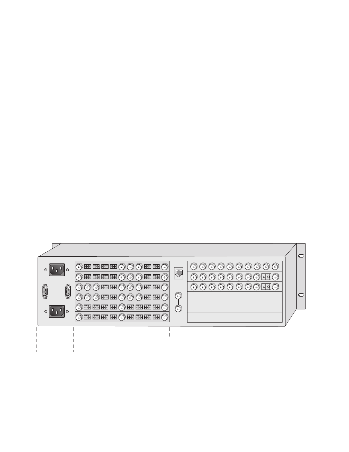
Locate a vacant slot in the rear of the 3 RU frame (Figure 1) or the
2000T1DNG frame (Figure 2 on page 9).
Figure 1. 2000T3NG Frame, Rear View
Media section
rear slots 7-12
Network
and reference
input connections
Media section
rear slots 1-6
(with three 2000EMI blanks)
8318_08
8 2031RDA-SM/-MM Instruction Manual
Page 9
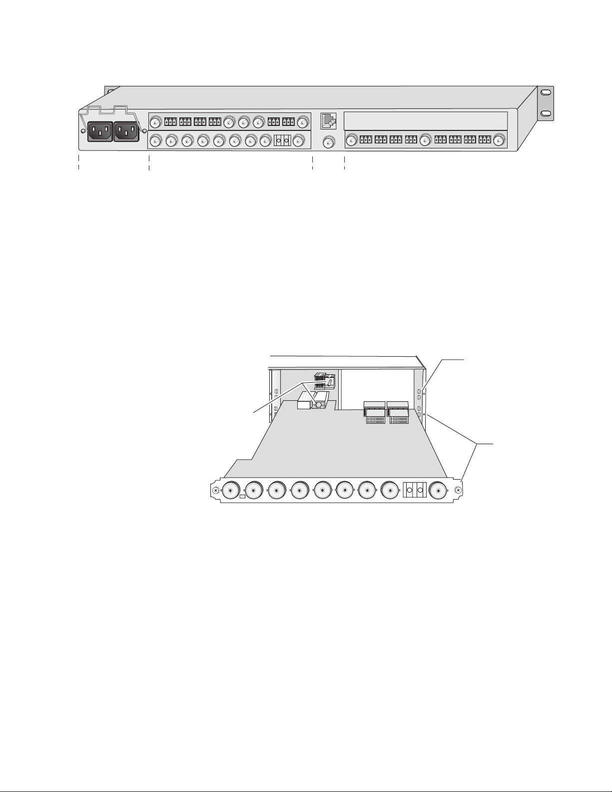
2.
Figure 2. 2000T1DNG Frame, Rear View
1
3
J101
J102
2
4
3.
4.
Installation
Power connections
Media section
rear slots 3-4
Network
and reference
Media section
rear slots 1-2
(with one 2000EMI blank)
input connections
Install the module by inserting it into any rear slot of the frame as
illustrated in Figure 3.
Verify that the module connector seats properly against the midplane.
Secure the module to the rear of the frame with the two screw locks on
either side of the back panel using a crossblade screwdriver.
Figure 3. Installing 2031RDA-SM/-MM Module
2000 frame (rear view)
Alignment post
and receptacle
Board edge guides
(both sides)
Screw lock
(both sides)
8318_09
IN
J9
J10
SIG
J8 J6J7 J5 J4
FIBER IF
J3
2031RDA
-MM
J2
J1
INOUT
8318_01
2031RDA-SM/-MM Instruction Manual 9
Page 10
Installation
Cabling
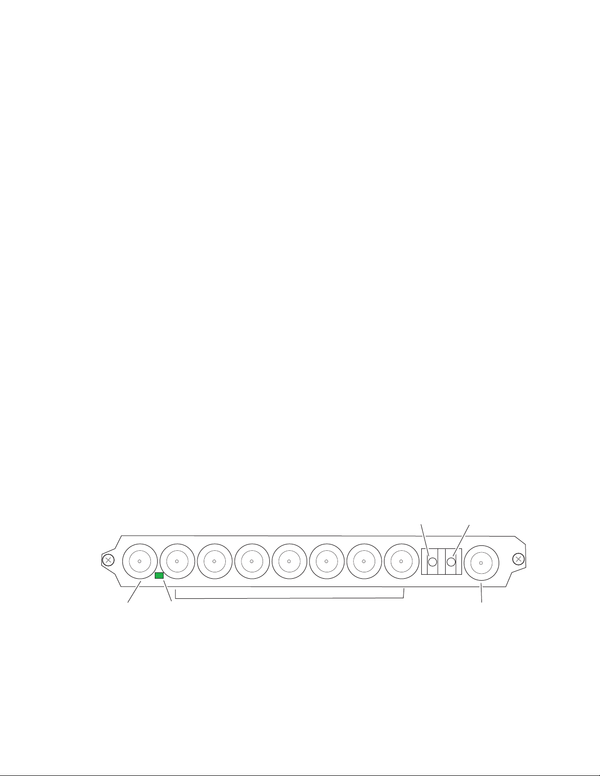
Cabling to the 2031RDA-SM/-MM module is done on the BNCs and the
fiber connector on the rear of the module. Refer to Figure 4 for a detailed
illustration of the rear connections referenced below.
The input can be either electrical or fiber optic and the desired input must
be enabled using an on-board jumper or with remote controls. The outputs
can be both electrical and fiber optic. The fiber optic output must be
enabled using an on-board jumper or remote controls.
For configuration, refer to Configuration and Monitoring on page 13.
Electrical Input
Connect an SDI electrical video input to BNC J10. This input must be
enabled for use during configuration.
Electrical Outputs
Fiber Input
Fiber Output
IN OUT
J10
SDI In
SIG
SIG LED
Connect electrical video destinations to any of the eight outputs at connectors J1, J3– J9. Terminate any unused outputs. These outputs are always
active and do not need to be enabled.
Connect a fiber input to the right side of the FIBER IF connector J2. This
input must be enabled for use in configuration.
The fiber output is available on the left side of the FIBER IF connector J2.
This output must be enabled for use in configuration.
Figure 4. 2031RDA-SM/-MM Input/Output Connectors
FIBER IF
INOUT
Fiber In
2031RDA
-MM
J2 J1
SDI Out 1
Fiber Out
OUT OUT OUT OUT OUT OUT OUT
J9
J8
J7
SDI Out 2-8
J6
J5
J4
J3
8318_02
10 2031RDA-SM/-MM Instruction Manual
Page 11

Power Up
Operation Indicator LEDs
(green on rear
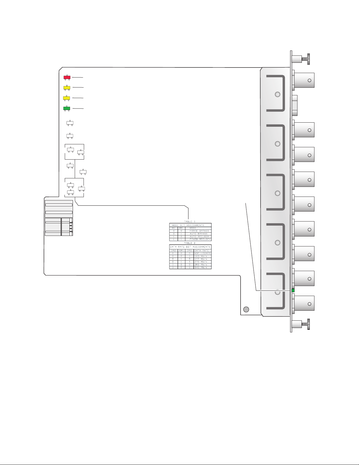
The on-board LED indicators are illustrated in Figure 5 on page 12. Upon
power-up, the green PWR LED should light and the yellow CONF LED
should illuminate for the duration of module initialization.
With a valid input signal connected, the green on-board PWR LED and the
SIG LED (visible from the rear) should be on. A red FAULT LED indicates
an error situation and, when noted with the other indicator LEDs, can indicate a specific problem area. Table 1 describes signal output and LED indi-
cations for the various combinations.
Table 1. Indicator LEDs and Conditions Indicated
LED Indication Condition
FAULT
(red)
COMM
(yellow)
CONF
(yellow)
PWR
(green)
SIG PRES
of module)
Off Normal operation
On continuously Module has detected internal fault.
Long flash No input signal or input signal does not meet selected standard.
Off No activity on frame communication bus.
Long flash Location command received by the module from a remote control system.
Short flash Activity present on the frame communication bus.
Off Module is in normal operating mode.
Short flash Module is initializing, changing operating modes or updating firmware.
Off No power to module or module’s DC/DC converter failed.
On Normal operation, module is powered.
Off Carrier input signal is present at either the coax or fiber optic input.
On No carrier input signal is present at either the coax or fiber optic input.
Power Up
Table 2 provides the possible input and output conditions that result from
different input signals and conditions.
Table 2. Input and Output Conditions
Input Condition Output Condition
Serial Digital Component (SDI) Serial Digital Component (SDI)
Other carrier Other carrier
No input Muted
Cable exceeding 200 meters Muted
2031RDA-SM/-MM Instruction Manual 11
Page 12
Power Up
FAULT COMM CONF PWR
OVER
SEL
REM
FIBER
CD
M1
SEE TABLE 1
SEE TABLE 2
DR2 DR0
Figure 5. LEDs and Configuration Switches
FAULT– (red) off during normal operation
COMM – (yellow)
CONF – (yellow)
PWR – (green) on during normal operation
M0
LD
DR1
Signal present – (green) on rear connector plate
8318_04
12 2031RDA-SM/-MM Instruction Manual
Page 13

Configuration and Monitoring
The 2031RDA-SM/-MM can be configured locally using on-board switches
or remotely using the 2000NET network interface GUI or a Newton Control
Panel. Operation of these control types is explained in detail in their respective sections of this manual.
Configuration and Monitoring
Note
Not all available functions are configurable with the local on-board controls.
Refer to the following sections for configuration instructions:
• Configuration Summary (page 13)
• Local On-board Configuration (page 14)
• Remote Configuration and Monitoring (page 16)
Configuration Summary
The configuration parameters and monitoring functions available with the
local on-board jumpers, web browser interface, and the Newton Control
Panel are summarized in Table 3. The parameter defaults, choices, ranges,
and resolution are provided for each function.
Table 3. Summary of 2031RDA-SM/-MM Configuration Functions
Function
Type
Input
Mode
Optic Tx Enabled or Disabled
Recall factory
defaults
1
Newton Control Panel operation for this module requires a 2000NET module running version 4.0.0 or later in the frame.
Default
Reverts to on-board
jumper settings
– See Default column
Range/Choices
Resolution
Coax or Fiber
Bypass
Auto
Auto Reclock
Manual 143M
Manual 177M
Manual 270M
Manual 360M
Manual 540M
Web Page/
Function Name
Settings/
Input pulldown
Settings/
Mode Pulldown
Settings/
Optic TX pulldown
Recall Factory Defaults
Recall Factory
Defaults
button
On-Board Jumper
Setting
J112 pins 1-2 = Electrical Input
J112 pins 2-3 = Fiber Input
J106 pins 1-2 = AUTO
J106 pin 2 only =270 Mb
J106 pins 2-3 = BYPASS
J110 pins 1-2 = Fiber Tx En
J110 pins 2-3 = Fiber Tx Dis
Newton
Control
Panel
InpSel
Mode
OpticTx
N/A N/A
1
2031RDA-SM/-MM Instruction Manual 13
Page 14

Configuration and Monitoring
Local On-board Configuration
Jumpers are provided on the module for setting the following functions in
local mode:
• Local or Local/Remote control
• Auto/270 Mb/Bypass mode
• Fiber Tx enable/disable
• Fiber Input or Electrical Input enable
Refer to Figure 6 on page 15 for jumper locations.
Local or Local/Remote Control
Set jumper J107 to LOCAL (pins 1-2) to lock out remote control or LOCAL
& REMOTE (pins 2-3) for both local and remote control.
Auto/270 Mb/Bypass
Set jumper J106 for AUTO (pins 1-2) to enable auto reclocking (for signal
data rates of 143 Mb/s, 177 Mb/s, 270 Mb/s, or 360 Mb/s), 270 Mb
reclocking only (jumper pin 2 only), or BYPASS (pins 2-3) to bypass
reclocking (for signals with data rates of 50 Mb/s to 540 Mb/s).
Fiber TX Enable/Disable
Set jumper J110 to FIBER TX EN (pins 1-2) to enable the fiber output or
FIBER TX DIS (pins 2-3) to disable the fiber output.
Fiber or Electrical Input Enable
Set jumper J112 to ELEC INPUT (pins 1-2) to enable the electrical (BNC)
input or FIBER INPUT (pins 2-3) to enable the fiber input.
14 2031RDA-SM/-MM Instruction Manual
Page 15

J107
Figure 6. Onboard Jumper Locations
Remote Control Lockout
Jumper across pins 1–2
to lock out remote control.
LOCAL
J107
LOCAL
REMOTE
Jumper across pins 2–3
&
to enable remote and
local control.
Configuration and Monitoring
J106
J110
J112
Reclocking Modes
Pins 2–3 forces bypass function.
J106
BYPASS
AUTO
Pins 2 only forces
270Mb
270 Mb/s reclock.
Pins 1–2 selects auto reclock.
Fiber Input Select/Fiber Tx Enable
FIBER
Jumper J110 pins 1-2 to enable
J110
TX DIS
the fiber TX output or pins 2-3
FIBER
to disable the fiber output.
TX EN
FIBER
Jumper J112 pins 1-2 to enable
INPUT
the electrical coax input or
ELEC
pins 2-3 to enable the fiber input.
INPUT
J112
Jumper Positions for J106
Pins 2-3
Pin 2 only
Pins 1-2
2031RDA-SM/-MM Instruction Manual 15
8318_05
Page 16

Configuration and Monitoring
Remote Configuration and Monitoring
Configuration and monitoring can be performed using a web browser GUI
interface or a networked Newton Control Panel when the 2000NET
Network Interface module is present in the video frame. Each of these
interfaces is described below.
2000NET Module Information
Refer to the 2000NET Network Interface Module Instruction Manual for
information on the 2000NET Network Interface module and setting up and
operating the Kameleon 2000 frame network.
Newton Control Panel Configuration
A Newton Control Panel (hard or soft version) can be interfaced to the
Kameleon 2000 Series frame over the local network.
Note For Newton control of this module, the 2000NET module in the frame must
be running software version 4.0.0 or later.
Control panel access offers the following considerations for module configuration and monitoring:
• Ability to separate system level tasks from operation ones, minimizing
the potential for on-air mistakes.
• Ability to group modular products—regardless of their physical locations—into logical groups (channels) that you can easily manipulate
with user-configured knobs.
• Update software for applicable modules and assign frame and panel IP
addresses with the NetConfig Networking application.
• Recommended for real-time control of module configuration parameters, providing the fastest response time.
Note Not all module functions are available with the control panel, such as factory
default recalls. The available control panel controls for the module are listed
in Table 3 on page 13.
An example of the Newton Configurator is shown in Figure 7 on page 17.
16 2031RDA-SM/-MM Instruction Manual
Page 17

Figure 7. Newton Configurator Example
Configuration and Monitoring
Refer to the documentation that accompanies the Newton Modular Control
System for installation, configuration, and operation information.
Web Browser Interface
The web browser interface provides a graphical representation of module
configuration and monitoring.
Use of the web interface offers the following considerations:
• Provides complete access to all module status and configuration func-
tions, including factory parameter and name default recalls, slot configuration, and SNMP monitoring controls.
• Web access will require some normal network time delays for pro-
cessing of information.
• Configuration parameter changes may require pressing the
button or
become effective.
• Web interface recommended for setting up module signal and slot
names, and reporting status for SNMP and monitoring.
Refer to the Frame Status page shown in Figure 8 on page 18. The Kameleon and 2000 modules can be addressed by clicking either on a specific
module icon in the frame status display or on a module name or slot
number in the link list on the left.
Enter, upload processing time, and a manual screen refresh to
Apply
2031RDA-SM/-MM Instruction Manual 17
Page 18

Configuration and Monitoring
Note The physical appearance of the menu displays on the web pages shown in
Figure 8. 2000NET GUI
this manual represent the use of a particular platform, browser and version
of 2000NET module software. They are provided for reference only. Displays
will differ depending on the type of platform and browser you are using and
the version of the 2000NET software installed in your system. This manual
reflects 2000NET software version 3.2.2.
The Links section lists the frame and its current modules. The selected link's Status
page is first displayed and the sub-list of links for the selection is opened. The sub-list
allows you to select a particular information page for the selected device.
Content display section displays the information page
for the selected frame or module (frame slot icons are also
active links).
Refresh button for manual
update of page
8318_07
18 2031RDA-SM/-MM Instruction Manual
Page 19

2031RDA-SM/-MM Links and Web Pages
The 2000 GUI provides the following links and web pages for the
2031RDA-SM and 2031RDA-MM modules (Figure 9):
• Status – reports input and reference signal status and module informa-
tion (page 20),
• Settings – provides controls for setting input/output enables and
bypass and reclocking functions (page 22),
• Recall Factory Defaults – provides recall of factory defaults (page 24),
• Slot Config – provides a Locate Module function, Slot Identification
name and asset tag fields, and Slot Memory controls (page 25), and
• Software Update – gives information on software updating (page 27).
Figure 9. 2031RDA-SM/-MM Web Page Links
Configuration and Monitoring
Note The web page examples in this manual are shown for the 2031RDA-SM. The
web pages for the 2031RDA-MM are identical except for the Model name in
the heading or where otherwise indicated.
2031RDA-SM/-MM Instruction Manual 19
Page 20

Configuration and Monitoring
Status Web Page
The Status web page shows the status of the input signal(s) and the frame
Use
this
link
bus communication. Color coding of the display indicates the signal status.
In general, colors used on the frame and modules indicate:
• Green – normal operation, (Pass) or signal present, module locked.
• Red – On continuously = fault condition, flashing = internal error.
• Yellow – On continuously = active condition (configuration mode or
• Grey – not monitored, such as the Reference Signal and the Output
Information about the module, such as part number, serial number, hardware revision and software version, and Asset Tag number are given in a
read-only
The Status page for the 2031RDA-SM is illustrated in Figure 10.
Figure 10. 2031RDA-SM Status Web Page
communication), flashing in sequence = module locator function.
Signal(s) for this module.
Properties section at the bottom of the display.
20 2031RDA-SM/-MM Instruction Manual
Page 21

Configuration and Monitoring
The Status page for the 2031RDA-MM is illustrated in Figure 11.
Figure 11. 2031RDA-MM Status Web Page
2031RDA-SM/-MM Instruction Manual 21
Page 22

Configuration and Monitoring
Settings Web Page
The Settings web page (Figure 12) provides both status reporting and controls for the module.
Use
this
link
The following read-only status reports are provided:
•
•
•
•
Figure 12. Settings Web Page
Coax In – reports the presence of a signal carrier on the coax input.
Optic In – reports the presence of a signal carrier on the optic input.
Reclocker – reports the reclocking status as Locked, Unlocked, or N/A (when
set for Bypass).
Auto Rate – reports the currently detected bit rate or N/A if mode is set to
Bypass or
locked.
Unknown if mode is Auto or Auto Reclock and signal is not
22 2031RDA-SM/-MM Instruction Manual
Page 23

Configuration and Monitoring
The following parameter controls are provided on the Settings web page.
Select the
Apply button after each parameter selection.
Input
Select Coax or Fiber as the input to the module.
Mode
Set the reclocking mode to one of the following with the menu pulldown:
•
Bypass – reclocking is completely bypassed. The input signal passes
directly to the outputs without reclocking.
•
Auto – if the module detects the input signal as one of the SMPTE
standard definition rates (143 Mb/s, 177 Mb/s, 270 Mb/s,
360 Mb/s, or 540 Mb/s), it will reclock the signal at that rate. If one
of these rates is not detected, the module will not reclock the signal
(bypass the reclocker) and distribute the signal to the outputs.
•
Auto Reclock – if the module detects the input signal as one of the
SMPTE standard definition rates (143 Mb/s, 177 Mb/s, 270 Mb/s,
360 Mb/s, or 540 Mb/s), it will reclock the signal at that rate. If one
of these rates is not detected, the signal will not be reclocked and
will be passed to the output as is (corrupted).
Note This mode will not reclock/bypass DVB-ASI signals reliably. Use the Auto
mode for these signal types.
• Manual 143Mb – the module will attempt to reclock the input signal
at 143 Mb/s. If this signal rate is not detected, the signal will not be
reclocked and will be passed to the output as is (corrupted).
•
Manual 177Mb – the module will attempt to reclock the input signal
at 177 Mb/s. If this signal rate is not detected, the signal will not be
reclocked and will be passed to the output as is (corrupted).
•
Manual 270Mb – the module will attempt to reclock the input signal
at 270 Mb/s. If this signal rate is not detected, the signal will not be
reclocked and will be passed to the output as is (corrupted).
•
Manual 360Mb – the module will attempt to reclock the input signal
at 360 Mb/s. If this signal rate is not detected, the signal will not be
reclocked and will be passed to the output as is (corrupted).
•
Manual 540Mb – the module will attempt to reclock the input signal
at 540 Mb/s. If this signal rate is not detected, the signal will not be
reclocked and will be passed to the output as is (corrupted).
Optic TX
Use this control to enable or disable the optical output of the module.
2031RDA-SM/-MM Instruction Manual 23
Page 24

Configuration and Monitoring
Recall Factory Defaults Web Page
The Recall Factory Defaults web page (Figure 13) provides a Recall Fact.
Default Button to restores the module to the default values shown in Table 3
on page 13.
Use
this
link
Figure 13. Recall Factory Defaults Web Page
24 2031RDA-SM/-MM Instruction Manual
Page 25

Use
this
link
Slot Config Web Page
Use the Slot Config web page (Figure 14 on page 26) to perform the following functions on the 2031RDA-SM/-MM module:
•
Locate Module – selecting the Flash radio button flashes the yellow
COMM LED on the front of the module so it can be located in the frame.
•
Slot Identification – You may identify the module by typing a specific
name in the
module and travels with the 2000NET module if it is moved to another
frame. Select
Configuration and Monitoring
Name field. The assigned name is stored on the 2000NET
Default to enter the factory default module name.
You may also assign a name to the input signal in the
field. Select
An asset identification of up to 16 characters may be entered in the
Tag field. This will appear on the module Status web page and in the
NetConfig inventory report.
•
Slot Memory – the slot configuration for each media module is automati-
cally saved periodically (once an hour) to the 2000NET module in that
frame. You may also select the
save the current configuration for this slot. The configuration is saved
on the 2000NET module. If the 2000NET module is removed or
powered down, the stored configurations are not saved.
When the
ration saved to this slot is saved as slot memory. When the current
module is removed and another module of the same type is installed,
the configuration saved to the 2000NET module will be downloaded to
the new module. The box must be checked before the current module
with the saved configuration is removed.
•
Frame Heath Reporting – the reporting of Slot Fault, Signal Loss, and Ref-
erence Loss can be enabled or disabled to the Frame Health connector
on the rear of the Kameleon frame by selecting or deselecting the corresponding checkbox.
Default to enter the factory default signal name.
Learn Module Config button at any time to
Restore upon Install box has been checked, the current configu-
Input Signal Name
Asset
•
Hardware Switch Controls – a read-only status report of 2000NET module
switch settings for Module Status Reporting and Asynchronous Status
Reporting (dipswitch S1 segment 7 and dipswitch S2 segment 1). These
functions must be enabled for the following Slot SNMP Trap Reports to
function.
•
Slot SNMP Trap Reports – displayed only when the SNMP Agent software
has been installed on the 2000NET module. Slot SNMP traps can be
enabled only when the hardware switches for Module Fault reporting
and Asynchronous Status reporting are in enabled on the 2000NET
module.
The enabled SNMP traps will be reported to any SNMP manager that
is identified as an SNMP Report Destination in 2000NET configuration.
Trap severity is read-only hard-coded information that is interpreted
and responded to by the SNMP Manager software configuration.
2031RDA-SM/-MM Instruction Manual 25
Page 26

Configuration and Monitoring
Figure 14. 2031RDA-SM/-MM Slot Config Web Page
26 2031RDA-SM/-MM Instruction Manual
Page 27

Use
this
link
Configuration and Monitoring
Software Update Web Page
The Software Update web page (Figure 15) indicates that module software
updates via the web or using the NetConfig networking application are not
supported. For instructions on updating to the latest software, refer first to
the 2031RDA-SM/-MM Release Notes that accompany the software
update for complete details.
Currently, the only recommended method of software updating is done
with a software kit (8900-FLOAD-CBL) that includes a CD-ROM with the
current software files and a serial cable assembly available from Grass
Valley.
Refer to the 8900-FLOAD-CBL Software Upgrade Instruction Manual in pdf
format on the CD-ROM for complete updating instructions and the
required software files for the 2031RDA-SM/-MM.
Figure 15. Software Update Web Page
2031RDA-SM/-MM Instruction Manual 27
Page 28

Status Monitoring
Status Monitoring
This section provides a summary of status monitoring and reporting for a
Kameleon 2000 Series system. It also summarizes what status items are
reported and how to enable/disable reporting of each item. There are a
number of ways to monitor status of modules, power supplies, fans and
other status items depending on the method of monitoring being used.
2000 Frame status will report the following items:
• Power supply health,
• Status of fans in the frame front cover,
• Temperature,
• Module health, and
• Frame bus status.
Module health status will report the following items:
• Internal module state (and state of submodule or options enabled)
including configuration errors (warning), internal faults, and normal
operation (Pass).
LEDs
• Signal input states including valid/present (pass), not present or
invalid (warning), not monitored, and not available (no signal inputs).
• Reference input states including locked/valid (pass), not
locked/invalid (warning), and not monitored.
• Signal output states with reporting functionality (reference output).
LEDs on modules in the frame and on the front of the 2000 frames indicate
status of the frame and the installed power supplies, fans in the front
covers, and modules.
When a red FAULT LED is lit on a frame front cover, the fault will also be
reported on the 2000NET or Frame Monitor module. The LEDs on the front
of these modules can then be read to determine the following fault conditions:
• Power Supply 1 and 2 health,
• Fan rotation status,
• Frame over-temperature condition,
• Frame Bus fault (2000NET only), and
• Module health bus.
28 2031RDA-SM/-MM Instruction Manual
Page 29

In general, LED colors used on the frame and modules indicate:
• Green – normal operation, (Pass) or signal present, module locked.
• Red – On continuously = fault condition, flashing = configuration error.
• Yellow – On continuously = active condition (configuration mode or
communication), flashing in sequence = module locator function.
Status LEDs for this module are described in LEDs on page 28. LEDs for the
2000NET module are described in the 2000NET Network Interface Instruction
Manual.
Frame Alarm
Connection and use of the Frame Alarm is covered in detail in the 2000NET
Network Interface Instruction Manual.
Web Browser Interface
Status Monitoring
When the 2000NET module is installed in the frame, a web browser GUI
can indicate frame and module status on the following web pages:
• Frame Status web page – reports overall frame and module status in
graphical and text formats.
• Module Status web page – shows specific input and reference signal
status to the module along with enabled options and module versions.
• A Status LED icon on each web page to report communication status
for the frame slot and acts as a link to the Status page where warnings
and faults are displayed (2000NET version 3.0 or later).
In general, graphics and text colors used indicate the following:
• Green = Pass – signal or reference present, no problems detected.
• Red = Fault – fault condition.
• Yellow = Warning – signal is absent, has errors, or is mis-configured.
• Grey = Not monitored (older 2000 module).
• White = Not present.
Status reporting for the frame is enabled or disabled with the configuration
DIP switches on the 2000NET module. Most module status reporting items
can be enabled or disabled on individual configuration web pages.
2031RDA-SM/-MM Instruction Manual 29
Page 30

Status Monitoring
SNMP Reporting
The Kameleon Series system uses the Simple Network Monitoring Protocol
(SNMP) internet standard for reporting status information to remote monitoring stations. When SNMP Agent software is installed on the 2000NET
module, enabled status reports are sent to an SNMP Manager such as the
Grass Valley’s NetCentral application.
There are both hardware and software report enable switches for each
report. Both must be enabled for the report to be sent. Software report
switches are set on the 2000NET Configuration page for the Frame, the
2000NET module, and each module slot. Refer to the 2000NET Network
Interface Instruction Manual for installation instructions.
30 2031RDA-SM/-MM Instruction Manual
Page 31

Specifications
Specifications
Table 4. 2031RDA-SM/-MM Specifications
Parameter Value
Serial Digital Component Coax Input
Number and type of inputs 1 BNC
Input impedance 75 Ohm
Return loss > 15 dB from 5 MHz to 540 MHz
Signal type, auto-equalizing only 50 Mb/s to 540 Mb/s: rise/fall time – 20 to 80%, 400-800 ps,
Signal type, auto-equalizing and reclocking SMPTE 259M-1997 with the following bit rate tolerances:
Auto equalization cable lengths
(for any of the above signal types)
Input jitter tolerance ≥ 1 UI p-p from 10 Hz to 200 Hz
Serial Digital Component Fiber Input
Connector LC (1 input)
Fiber types 2031RDA-MM: multimode complying with
Wavelength 1270-1355 nm
Input power 2031RDA-MM: -28 dB (minimum) to -7.5 dB (maximum)
Signal type Same as Signal type, auto-equalizing only and Signal type,
Fiber length 2031RDA-MM: 2 kilometers minimum at 270 Mb/s
Jitter (on any specified signal type) > 0.2 UI p-p, 10 Hz to 10 MHz
Serial Digital Component Coax Outputs
Connector BNC (8 outputs)
Output impedance 75 Ω
Return loss > 15 dB from 5 MHz to 540 MHz
Signal level SDI 800 mV p-p, ± 10% maximum
Rise/fall time 400-800 ps
Output polarity Non-inverted
Output jitter < 0.2 UI p-p
signal level – 800 mV ± 10%)
143 Mb/s ± 5%
177 Mb/s ± 5%
270 Mb/s ± 5%
360 Mb/s ± 5%
ETSI TR 101 891v1.1.1 (DVB-ASI) with the following bit rate tolerance: 270 M/b/s ± 5%
SMPTE 344M-2000 with the following bit rate tolerance:
540 Mb/s± 5%
Up to 300 m of Belden 1694A cable for bit rates up to 270 Mb/s
Up to 100 m of Belden 1694A cable for bit rates > 270 Mb/s and
< 540 Mb/s
≥ 0.2 UI p-p from 200 Hz to 15 MHz
ANSI/TIA/EIA-492AAAA-A (maximum attenuation of 1.5 dB per
kilometer at 1310 nm)
2031RDA-SM: singlemode complying with
ANSI/TIA/EIA-492CAAA (maximum attenuation of 1.0 dB per kilometer at 1310 nm)
2031RDA-SM: -20 dB (minimum) to 0 dB (maximum)
auto-equalizing and relocking above
2031RDA--SM: 7 kilometers minimum at 270 Mb/s
2031RDA-SM/-MM Instruction Manual 31
Page 32

Specifications
Table 4. 2031RDA-SM/-MM Specifications - (continued)
Parameter Value
Serial Digital Component Fiber Outputs
Connector LC (1 output)
Fiber types 2031RDA-MM: multimode complying with
ANSI/TIA/EIA-492AAAA-A (maximum attenuation of 1.5 dB per
kilometer at 1310 nm)
2031RDA-SM: singlemode complying with
ANSI/TIA/EIA-492CAAA (maximum attenuation of 1.0 dB per kilometer at 1310 nm)
Wavelength 1290-1330 nm
Output power -12 to -7.5 dBm
Standard Other than LC connector, conforms to SMPTE 297-2000
Polarity Non-inverting
Output jitter < 0.2 UI
Power
Input power maximum < 6 W
Environmental
Frame temperature range See Kameleon 2000 frame specification
Operating humidity range 0 to 90% non condensing
Non-operating temperature -10 to 70 ° C
32 2031RDA-SM/-MM Instruction Manual
Page 33

Service
Power-up Diagnostics Failure
Troubleshooting
Service
The 2031RDA-SM/-MM modules make extensive use of surface-mount
technology and programmed parts to achieve compact size and adherence
to demanding technical specifications. Circuit modules should not be serviced in the field unless otherwise directed by Customer Service.
If the module has not passed self-diagnostics, do not attempt to troubleshoot. Return the unit to Grass Valley (see Module Repair).
If your module is not operating correctly, proceed as follows:
• Check frame and module power. If power is not present, check the fuse
and voltage testpoints on the module as illustrated in Figure 16.
• Check for presence and quality of input signals.
• Verify that source equipment is operating correctly.
• Check cable connections.
Figure 16. Location of Module Fuse
Voltage
Test Points
125V
+24V +5V GND
J108
J108
F1
2A
Fuse: F1, 2A, 125V
TP 6
GND
GND+3.3V
8318_03
2031RDA-SM/-MM Instruction Manual 33
Page 34

Functional Description
Module Repair
If the module is still not operating correctly, replace it with a known good
spare and return the faulty module to a designated Grass Valley repair
depot. Call your Grass Valley representative for depot location.
Refer to Contacting Grass Valley at the front of this document for the Grass
Valley Customer Service Information number.
Functional Description
A block diagram of the 2031RDA-SM/-MM is shown in Figure 17.
Figure 17. 2031RDA-SM/-MM Block Diagram
J9
J8
Optical
Input
Coax
Input
2000
Frame
Bus
Input Processing
The wideband serial SD signal enters the module from rear BNC J10
(labeled In) to an input amplifier. It is then equalized for the specified cable
lengths in the equalizer circuit.
Optical
Receiver
Equalizer
On-board
Jumpers
Microprocessor
Reclocker
Front
LEDs
Bypass
Optical
Transceiver
J7
J6
Electrical
J5
J4
J3
J1
8
Coax
Outputs
Optical
Output
8318_06
34 2031RDA-SM/-MM Instruction Manual
Page 35

Microprocessor
The main functions of the microprocessor include:
• Providing remote control and monitoring capability for the module
(through ethernet),
• Communicating with equalizer IC to monitor signal present status,
• Relaying module status through on-board LEDs, and
• Configuring module components at power up.
Output Processing
Driver circuits drive each of the eight serial digital outputs to the rear BNCs
J2 through J9. These outputs are non-inverting and are in-phase with each
other.
Power Supply
Functional Description
Power is fed from +24 V rails of the frame’s switching power supply. Each
stage of the module receives its own, separate, highly regulated and filtered
power source. The power input is protected by a socketed fuse (Figure 16
on page 33).
2031RDA-SM/-MM Instruction Manual 35
Page 36

Functional Description
36 2031RDA-SM/-MM Instruction Manual
Page 37

Index
Numerics
2000 frame
status reporting
2000NET module
software requirements
8900-Fload/Bload 27
28
16
A
Asset Tag assignment 25
B
block diagram 34
C
cabling
inputs
outputs 10
circuit descriptions 34
COMM LED 11, 25
CONF (configuring) LED 11
configuration
Remote, GUI
configuration summary 13
control panel 16
10
16
D
F
FAQ database 2
FAULT LED 11
troubleshooting 28
fault table 11
Frame Health Reporting
enabling and disabling
Frame Status web page 29
frequently asked questions 2
fuse 33, 35
25
G
graphical user interface (GUI) 19
Grass Valley web site 2
I
input signal name
assigning
inputs 10
specifications 31
installation 8
25
L
Learn Module Config button 25
LEDs 11
locate module function 25
documentation online 2
Dual Optical Transmitter submodule
summary table
13
M
module health status 28
Module Status web page 29
E
enable SNMP 30
environmental 32
2031RDA-SM/-MM Instruction Manual 37
N
Newton Control Panel
2000NET software requirement
control summary table 13
13
Page 38

Index
overview 16
O
online documentation 2
outputs 10
P
PWR LED 11
R
Recall Factory Defaults web page 24
repair depot 33
report enable switches 30
S
Settings web page 22
SIG LED (rear) 11
Slot Config
hardware switch controls
slot identification 25
slot memory 25
Slot Config web page 25
SNMP reporting
enabling
overview 30
software download from web 2
Software Update web page 27
specifications 8, 31
status monitoring 28
Status web page 20
25
25
Grass Valley 2
software download 2
T
troubleshooting 33
W
web browser
overview
web site
documentation
FAQ database 2
38 2031RDA-SM/-MM Instruction Manual
17
2
 Loading...