

Page 1

2010RDA-16
AES/EBU DIGITAL AUDIO RECLOCKING DA
Instruction Manual
SOFTWARE VERSION 1.0.1
071826800
NOVEMBER 2003
Page 2

Contacting Grass Valley
Region Voice Fax Address Web Site
North America (800) 547-8949
Support: 530-478-4148
Pacific Operations +852-2585-6688
Support: 852-2585-6579
U.K., Asia, Middle East +44 1753 218 777 +44 1753 218 757
France +33 1 45 29 73 00
Germany, Europe +49 6150 104 782 +49 6150 104 223
Copyright © Thomson Broadcast and Media Solutions All rights reserved.
Grass Valley Web Site
Sales: (530) 478-3347
Support: (530) 478-3181
+852-2802-2996
Grass Valley
P.O. Box 599000
Nevada City, CA 959597900 USA
www.thomsongrassvalley.com
The www
Online User Documentation
.thomsongrassvalley.com web site offers the following:
— Current versions of product catalogs, brochures,
data sheets, ordering guides, planning guides, manuals, and release notes
in .pdf format can be downloaded.
FAQ Database
— Solutions to problems and troubleshooting efforts can be
found by searching our Frequently Asked Questions (FAQ) database.
Software Downloads
— Software updates, drivers, and patches can be down-
loaded.
2 2010RDA-16 Instruction Manual
Page 3

Contents
Preface
. . . . . . . . . . . . . . . . . . . . . . . . . . . . . . . . . . . . . . . . . . . . . . . . . . . . . . . . . . . . . . . . . . . . . 5
About This Manual . . . . . . . . . . . . . . . . . . . . . . . . . . . . . . . . . . . . . . . . . . . . . . . . . . . . . 5
Introduction . . . . . . . . . . . . . . . . . . . . . . . . . . . . . . . . . . . . . . . . . . . . . . . . . . . . . . . . . . . 7
Installation . . . . . . . . . . . . . . . . . . . . . . . . . . . . . . . . . . . . . . . . . . . . . . . . . . . . . . . . . . . . 8
Local Onboard Module Configuration. . . . . . . . . . . . . . . . . . . . . . . . . . . . . . . . . . . 8
Module Placement in the Kameleon 2000 Frame . . . . . . . . . . . . . . . . . . . . . . . . . . 9
Cabling . . . . . . . . . . . . . . . . . . . . . . . . . . . . . . . . . . . . . . . . . . . . . . . . . . . . . . . . . . . . 12
2010RDA-16 COAX Passive Rear Module . . . . . . . . . . . . . . . . . . . . . . . . . . . . . 12
Power Up . . . . . . . . . . . . . . . . . . . . . . . . . . . . . . . . . . . . . . . . . . . . . . . . . . . . . . . . . . . . 14
Operation Indicator LEDs . . . . . . . . . . . . . . . . . . . . . . . . . . . . . . . . . . . . . . . . . . . . 14
Remote Monitoring. . . . . . . . . . . . . . . . . . . . . . . . . . . . . . . . . . . . . . . . . . . . . . . . . . . . 16
2010RDA-16 Links and Web Pages. . . . . . . . . . . . . . . . . . . . . . . . . . . . . . . . . . . . . 17
Status Page . . . . . . . . . . . . . . . . . . . . . . . . . . . . . . . . . . . . . . . . . . . . . . . . . . . . . . . 18
Input Status Output Mode Page . . . . . . . . . . . . . . . . . . . . . . . . . . . . . . . . . . . . . 19
Slot Config Page . . . . . . . . . . . . . . . . . . . . . . . . . . . . . . . . . . . . . . . . . . . . . . . . . . . 20
Software Update Page. . . . . . . . . . . . . . . . . . . . . . . . . . . . . . . . . . . . . . . . . . . . . . 22
Control Panel Monitoring . . . . . . . . . . . . . . . . . . . . . . . . . . . . . . . . . . . . . . . . . . . . 22
Specifications . . . . . . . . . . . . . . . . . . . . . . . . . . . . . . . . . . . . . . . . . . . . . . . . . . . . . . . . . 23
Service. . . . . . . . . . . . . . . . . . . . . . . . . . . . . . . . . . . . . . . . . . . . . . . . . . . . . . . . . . . . . . . 24
Functional Description . . . . . . . . . . . . . . . . . . . . . . . . . . . . . . . . . . . . . . . . . . . . . . . . . 25
AES Receivers. . . . . . . . . . . . . . . . . . . . . . . . . . . . . . . . . . . . . . . . . . . . . . . . . . . . . . . 25
Routing and Control FPGA . . . . . . . . . . . . . . . . . . . . . . . . . . . . . . . . . . . . . . . . . . . 26
Controller . . . . . . . . . . . . . . . . . . . . . . . . . . . . . . . . . . . . . . . . . . . . . . . . . . . . . . . . . . 26
Power Supply. . . . . . . . . . . . . . . . . . . . . . . . . . . . . . . . . . . . . . . . . . . . . . . . . . . . . . . 26
Index
2010RDA-16 Instruction Manual 3
. . . . . . . . . . . . . . . . . . . . . . . . . . . . . . . . . . . . . . . . . . . . . . . . . . . . . . . . . . . . . . . . . . . . . . 27
Page 4

Contents
4 2010RDA-16 Instruction Manual
Page 5

Preface
About This Manual
This manual describes the features of a specific 2000 Series module in the
Kameleon Media Processing System. As part of this module family, it is
subject to Safety and Regulatory Compliance described in the 2000 Series
frame and power supply documentation (see the
tion Manual
).
2000 Series Frames Instruc-
2010RDA-16 Instruction Manual 5
Page 6

Preface
6 2010RDA-16 Instruction Manual
Page 7

2010RDA-16 AES/EBU Digital Audio Reclocking DA
Introduction
The 2010RDA-16 is a single or dual operation 75
digital audio reclocking distribution amplifier. The 2010RDA-16 is configured with an on-board jumper to provide a single input with sixteen
outputs or as a dual, two input, eight output DA providing two distinct distribution amplifiers on a single card. Reclocking provides jitter reduction at
a variety of sample rates for the most demanding AES/EBU requirements.
The 2010RDA-16 modules feature:
•Unbalanced digital audio SMPTE 276M,
• 75
• Single mode with one input and 16 outputs,
•Dual mode with two inputs, each with eight outputs,
•Auto-detect data reclocking at sample rates of 32, 44.1, 48 or 96 kHz,
•Housed in the Kameleon frame with other 2000 series audio and video
•Remote control via Ethernet frame interface with web browser GUI or
• Loss of signal detection and SNMP reporting.
Ω unbalanced input/output I/O,
modules,
Newton control panel, and
Ω unbalanced AES/EBU
2010RDA-16 Instruction Manual 7
Page 8
Installation
Installation
Installation of the 2010RDA-16 module is a process of:
•Configuring the module for Single or Dual operation with an on-board
jumper, JP5,
• Placing the passive rear module in a rear frame slot,
• Placing the media module in the corresponding front slot, and
•Cabling and terminating signal ports.
The 2010RDA-16 module can be plugged in and removed from a Kameleon
2000 Series frame with power on. When power is applied to the module,
LED indicators reflect the initialization process (see
Power Up
on page 14).
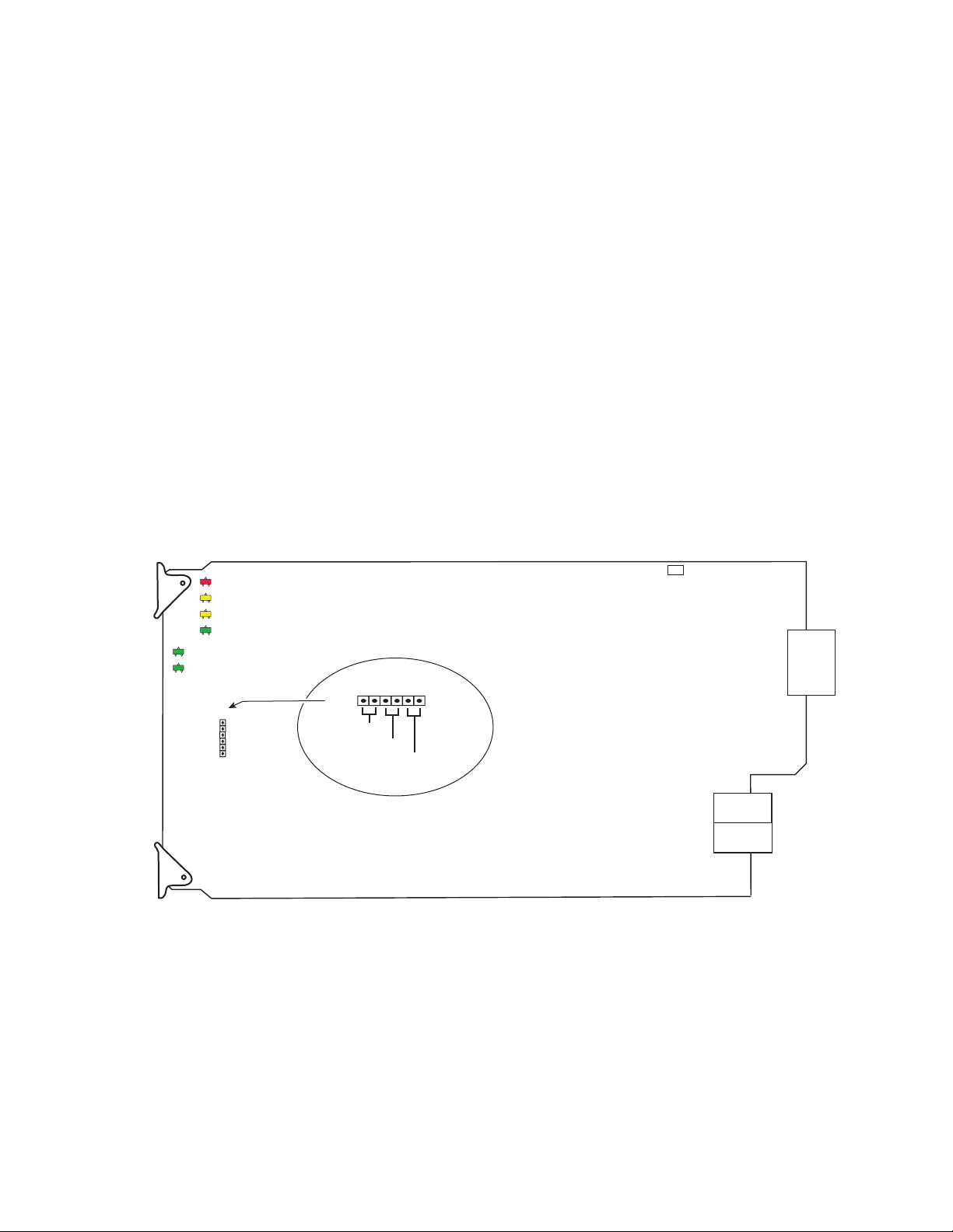
Local Onboard Module Configuration
The 2010RDA-16 module is configured locally for Single or Dual operation
using the jumper shown in Figure 1.
Figure 1. Module Configuration Switches and LEDs
FAULT
GRASS VALLEY GROUP 2010RDA-16 16 OUT UNBALANCED AES DA 671-6557-
COMM CONF PWR
LOCK1
LOCK2
JP5
1
JP5
SINGLE
6
DUAL
QUAD
(Not used)
8268_08
Set jumper JP5 for one of the following operating modes:
Single (pins 1/2)
•1 input by 16 outputs
Dual (pins 3/4)
•2 inputs by 8 outputs each
8 2010RDA-16 Instruction Manual
Page 9

Module Placement in the Kameleon 2000 Frame
There are twelve slot locations in both the front and rear of a Kameleon
3 RU frame to accommodate 2000 Series modules. The 2010RDA-16
module set consists of a front media module and a passive rear module that
require two module slots.
Each 2010RDA-16 front media module plugs into the front of the 2000
frame mid-plane. The passive rear module plugs into the corresponding
rear slot to provide the input and output interface connectors. Stacked
BNCs on the passive rear module require two rear slots. A frame fully
stuffed with 2010RDA-16 front and rear modules will accommodate up to
six module sets as shown in Figure 2.
To install a 2010RDA-16 module set in the frame:
1.
Locate a vacant slot in slot 2, 4, 6, 8, 10, or 12 of the rear of the 3 RU
frame (Figure 2). The passive rear module uses two slots.
Installation
Mid-frame motherboard
with power and
communication buses
Slot 8
Slot 10
Slot 12
Figure 2. 3 RU Frame, Rear View
Slot 2
Slot 4
Slot 6
8268_05
Use rear media module slots 2, 4, and 6Use rear media module slots 8, 10, and 12
2010RDA-16 Instruction Manual 9
Page 10

Installation
2.
3.
4.
Insert the passive rear module into vacant rear slot 2, 4, 6, 8, 10, or 12 of
the frame as illustrated in Figure 3.
Figure 3. Installing Passive Rear Module
2000 frame (rear view)
Alignment post
and receptacle
Board edge guides
(both sides)
2010
RDA-16
Screw locks
(both sides)
8268_03
2010RDA-16 Passive Rear Module
Verify that the module connector seats properly against the midplane.
Using a crossblade screwdriver, tighten the four screw locks to secure
the module in the frame.
5.
Locate the front slot 2, 4, 6, 8, 10, or 12 in the frame corresponding to the
rear module circuit board. The 3 RU frame front view is illustrated in
Figure 4. Module slots for the 2010RDA-16 are highlighted in gray.
Figure 4. 2000 Series 3 RU Frame, Front Slots
(1)
(2)
(3)
(4)
(5)
(6)
(7)
(8)
(9)
(10)
(11)
(12)
Install Front Media modules
into slots 2, 4, 6, 8, 10, and 12.
8268_01
10 2010RDA-16 Instruction Manual
Page 11

6.
7.
8.
With the component side up, insert the front media module in the
corresponding front slot (see Figure 5).
Verify that the module connector seats properly against the midplane
and rear module connector.
Press firmly on both ejector tabs to seat the module.
Figure 5. Installing Front Media Module
2000 Frame (front view)
Installation
Alignment post and receptacle
Board edge
guides
2010RDA-16
Board edge
guides
8268-10
2010RDA-16 Instruction Manual 11
Page 12

Installation
Cabling
All cabling to the modules is done on the corresponding passive rear
module (PRM) at the back of the 2000 frame. The passive rear modules for
the 2010RDA-16 is a COAX PRM with 75
Refer to the instructions that follow for cabling the COAX passive rear
module for single or dual mode.
2010RDA-16 COAX Passive Rear Module
Ω BNC I/O.
CH 2
OUT
The 2010RDA-16 passive rear module provides eighteen 75
BNC connectors for single or dual operation. Refer to Figure 6 for an illustration of the 2010RDA-16 passive rear module.
The module must be jumpered during configuration for the desired mode
of operation. Refer to
Figure 6. COAX Passive Rear Module
CH2 Out J6 – J9 and J15 – J18
Local Onboard Module Configuration
Dual Mode
J6J7J8J9 J5 J3J4 J2
CH 1
OUT
J15J16J17J18 J14 J12J13 J11
Outputs J2 – J9 and J11 – J18
Single Mode
CH1 Out J2 – J5 and J11 – J14
Ω (unbalanced)
on page 8.
CH1 In
J1
IN 1
J10
IN 2
CH2 In
2010
RDA-16
8268_02
12 2010RDA-16 Instruction Manual
Page 13

Refer to Table 1 for single and dual channel cabling.
Table 1. COAX PRM Cabling BNCs
Connector Single Mode Dual Mode
J1 Ch 1 In Ch 1 In
J2 Ch 1 Out 1 Ch 1 Out 1
J3 Ch 1 Out 2 Ch 1 Out 2
J4 Ch 1 Out 3 Ch 1 Out 3
J5 Ch 1 Out 4 Ch 1 Out 4
J6 Ch 1 Out 5 Ch 2 Out 1
J7 Ch 1 Out 6 Ch 2 Out 2
J8 Ch 1 Out 7 Ch 2 Out 3
J9 Ch 1 Out 8 Ch 2 Out 4
J10 Not used Ch 2 In
J11 Ch 1 Out 9 Ch 1 Out 5
J12 Ch 1 Out 10 Ch 1 Out 6
J13 Ch 1 Out 11 Ch 1 Out 7
J14 Ch 1 Out 12 Ch 1 Out 8
J15 Ch 1 Out 13 Ch 2 Out 5
J16 Ch 1 Out 14 Ch 2 Out 6
J17 Ch 1 Out 15 Ch 2 Out 7
J18 Ch 1 Out 16 Ch 2 Out 8
Installation
2010RDA-16 Instruction Manual 13
Page 14

Power Up
Power Up
Operation Indicator LEDs
The front LED indicators and configuration jumper are illustrated in
Figure 7. Upon power-up, the green PWR LED should light and the yellow
CONF LED should illuminate for the duration of module initialization.
With valid input signal(s) connected, the green PWR LED and the green
LOCK LED 1 (and LOCK 2 for dual mode) should be on for each audio
input.
Figure 7. Operation Indicator LEDs
FAULT
COMM CONF PWR
FAULT (red)
COMM (yellow)
LOCK1
LOCK2
CONF (yellow)
PWR (green)
LOCK 1 (green) Single Mode
LOCK 2 (green) Dual Mode
8268_07
14 2010RDA-16 Instruction Manual
Page 15

A red FAULT LED indicates an error situation and, with the other LEDs,
can indicate the operational conditions presented in Table 2. The table
describes signal output and LED indications for various input/reference
combinations and user settings.
Table 2. Indicator LEDs and Conditions Indicated
LED Indication Condition
FAULT
(red)
COMM
(yellow)
CONF
(yellow)
PWR
(green)
LOCK 1
(green)
LOCK 2
(green)
Off Normal operation.
On continuously Module has detected an internal fault.
Flashing AES input missing or Mode Jumper not installed
Off No activity on frame communication bus.
Long flash Location Command received by the module from a remote control system.
Short flash Activity present on the frame communication bus.
Off Module is in normal operating mode.
On continuously
Flashing Indicates rate of change of paddle-controlled analog setting.
Off No power to module or module’s DC/DC converter failed.
On continuously Normal operation, module is powered.
Off Module does not detect a valid AES input signal on channel 1.
On continuously Valid AES input signal is present on channel 1 and module is locked to it.
Off Module does not detect a valid AES input signal on channel 2 (dual mode only).
On continuously Valid AES input signal is present on channel 2 and module is locked to it.
Module is initializing, changing operating modes or updating firmware. Simultaneous CONF
and FAULT LEDs on indicate FPGA load error.
Power Up
2010RDA-16 Instruction Manual 15
Page 16

Remote Monitoring
Remote Monitoring
Monitoring of the 2010RDA-16 can be performed remotely using the
2000NET interface (see Figure 8) or the Newton control panel. This section
describes the GUI access to the module functions. Refer to the
Network Interface Module Instruction Manual
and operating the 2000 frame network.
2000NET
for information on setting up
Note
The 2000 modules can be addressed by clicking on a specific module icon
in the frame status display or on a module name or slot number in the link
list on the left.
Figure 8. 2000NET GUI
The Links section lists the frame and its current modules. The selected link's Status
page is first displayed and the sub-list of links for the selection is opened. The sub-list
allows you to select a particular information page for the selected device.
The physical appearance of the menu displays shown in this manual repre-
sent the use of a particular platform, browser and version of 2000NET
module software. They are provided for reference only. Displays will differ
depending on the type of platform and browser you are using and the version
of the 2000NET software installed in your system.
Content display section displays the information page
for the selected frame or module (frame slot icons are also
active links).
Refresh button for manual
update of page
Online Manual Link
8268_11
16 2010RDA-16 Instruction Manual
Page 17

Remote Monitoring
Use the
ware version 3.0 and later).
The
pdf format. Link configuration is done on the Frame Configuration page.
Refresh
Online Manual Link
button to update the display (available with 2000NET soft-
button can be set up to link to the documentation in
2010RDA-16 Links and Web Pages
The 2000 GUI provides the following links and displays for the
2010RDA-16 module (Figure 9):
• Status – reports input signal status and module information (page 18),
• Input Status Output Mode – reports mode of operation, rear module
information, input signal lock status and sample rate being detected by
the module (page 19),
• Slot Config – provides a Locate Module function and Slot Memory
(page 20), and
• Software Update – gives software update information (page 22)
Figure 9. 2010RDA-16 Display Links
2010RDA-16 Instruction Manual 17
Page 18

Remote Monitoring
Status Page
Use
this
link
The Status page (Figure 10) shows the status of the audio input signal(s)
and the frame bus communication. Color coding of the display indicates
the signal status. In general, colors used on the frame and modules indicate:
•Green – normal operation, (Pass) or signal present, module locked.
•Red – On continuously = fault condition, flashing = configuration error.
•Yellow – On continuously = active condition (configuration mode or
communication), flashing in sequence = module locator function.
Rear slot status is also reported if the rear module is the wrong type or
missing.
Information about the module, such as part number, serial number, hardware revision and software and firmware versions are given in a read-only
Properties
Figure 10. 2010RDA-16 Status Page
section at the bottom of the display.
18 2010RDA-16 Instruction Manual
Page 19

Input Status Output Mode Page
The Input Status Output Mode page (Figure 11) provides the following
status reporting items for the module:
Remote Monitoring
Use
this
link
•
•
•
•
Figure 11. 2010RDA-16 Input Status/Output Mode Display
indicates whether the on-board jumper is configured for
Mode
output mode. (Refer to
Dual
page 8.)
Rear Module Status
is installed.
Channel Lock
is present and module is locked to it) or
detect a valid AES signal).
Sample Rate
each channel as one of the following:
indicates the current input sample rate being detected by
reports that the Coax passive rear module (
indicates whether each channel is
Local Onboard Module Configuration
Unlocked
Out of Range, 32K, 44.1K, 48K, or 96K.
PRM-Coax
Locked
(valid AES signal
(module does not
Single
on
, or
)
2010RDA-16 Instruction Manual 19
Page 20

Remote Monitoring
Slot Config Page
Use
this
link
Use the Slot Config page (Figure 12 on page 21) to perform the following
functions on the 2010RDA-16 module:
•
Locate Module – selecting the On pulldown flashes the yellow COMM
and CONF LEDs on the front of the module so it can be located in the
frame.
•
Slot Identification – You may identify the module by typing a specific
name in the
module and travels with the 2000NET module if it is moved to another
frame. Select
•
Slot Memory – the slot configuration for each media module is automati-
cally saved periodically (once an hour) to the 2000NET module in that
frame. You may also select the
save the current configuration for this slot. The configuration is saved
on the 2000NET module. If the 2000NET module is removed or
powered down, the stored configurations are not saved.
Name field. The assigned name is stored on the 2000NET
Default to enter the factory default module name.
Learn Module Config button at any time to
When the
ration saved to this slot is saved as slot memory. When the current
module is removed and another module of the same type is installed,
the configuration saved to the 2000NET module will be downloaded to
the new module. The box must be checked before the current module
with the saved configuration is removed.
•
Hardware Switch Controls – a read-only status report of 2000NET module
switch settings for Module Status Reporting and Asynchronous Status
Reporting (dipswitch S1 segment 7 and dipswitch S2 segment 1). These
functions must be enabled for the following Slot SNMP Trap Reports to
function.
•
Slot SNMP Trap Reports – displayed only when the SNMP Agent software
has been installed on the 2000NET module. Slot SNMP traps can be
enabled only when the hardware switches for Module Fault reporting
and Asynchronous Status reporting are in enabled on the 2000NET
module.
The enabled SNMP traps will be reported to any SNMP manager that
is identified as an SNMP Report Destination in 2000NET configuration.
Trap severity is read-only hard-coded information that is interpreted
and responded to by the SNMP Manager software configuration.
Restore upon Install box has been checked, the current configu-
20 2010RDA-16 Instruction Manual
Page 21

Figure 12. 8964DEC Slot Config Page
Remote Monitoring
2010RDA-16 Instruction Manual 21
Page 22

Remote Monitoring
Software Update Page
Use
this
link
The Software update page (Figure 13) indicates that the 2010RDA-16 does
not support software downloads via the web or using the NetConfig networking application.
For instructions on updating to the latest software, refer to the 2010RDA-16
Release Notes that accompany any software update for complete details.
Figure 13. 2010RDA-16 Software Update Page
Control Panel Monitoring
The following status parameters for the 2010RDA-16 module can also be
monitored with a Newton Modular Control System control panel:
• Slot State
• Input Signal
•Mode
•Rear Module Status
•Channel 1 Sample Rate
•Channel 2 Sample Rate
•Channel 1 Lock
•Channel 2 Lock
Refer to the Newton Instruction Manual for configuration instructions.
22 2010RDA-16 Instruction Manual
Page 23

Specifications
Specifications
Table 3. 2010RDA-16 Specifications
Parameter Value
AES/EBU Inputs
Signal type AES3id – 1992 (transformer coupled)
Number of inputs 2 (jumper selectable for single or dual)
Connector type 75 Ω BNC on Passive Rear Module
Common mode range ± 10 V
Differential voltage range 200 mV to 12 V p-p
Sample rate 32 kHz, 44.1 kHz, 48 kHz, or 96 kHz
Input return loss > 15 dB (100 kHz – 10 MHz)
Maximum jitter < 6.5 ns RMS
AES Outputs
Signal type AES3id – 1992
Number of outputs Single mode -16, Dual mode – 8 per channel
Connector type 75 Ω BNC
Output level Unbalanced 1 V ± 0.1 p-p terminated in 75 Ω
Rise/fall time 30 to 44 ns (across 75 Ω load)
Sample rate 32 kHz, 44.1 kHz, 48 kHz, or 96 kHz
Input return loss > 15 dB (100 kHz – 6 MHz)
Maximum jitter < 6.5 ns RMS
Performance
DC offset <±1 mV
Electrical length (delay) 560 ns
Environmental
Frame temperature range 0 to 40° C
Operating humidity range 0 to 90% non-condensing
Non-operating temperature -10 to 70° C
Mechanical
Frame type Kameleon 2000 Series
Power Requirements
Supply voltage + 24 V
Power consumption < 3.3 Watts
2010RDA-16 Instruction Manual 23
Page 24

Service
Service
The 2010RDA-16 modules make extensive use of surface-mount technology and programmed parts to achieve compact size and adherence to
demanding technical specifications. Circuit modules should not be serviced in the field unless directed otherwise by Customer Service.
If your module is not operating correctly, proceed as follows:
•Check module power at JP1. If power is not present, check the fuse on
the +24 V input to the module as illustrated in Figure 14.
•Check for presence and quality of input signals.
•Verify that source equipment is operating correctly.
•Check cable connections.
Figure 14. Location of Module Fuse and Voltage Test Points
GRASS VALLEY GROUP 2010RDA-16 16 OUT UNBALANCED AES DA 671-6557-
Voltage
Test Points
GND
JP1
+5V
+3.3V
Fuse: 2 A FAST, 125 V
F1
8268_09
Refer to Figure 7 on page 14 for the location of PWR LED and Table 2 on
page 15 for proper LED indications.
If the module is still not operating correctly, replace it with a known good
spare and return the faulty module to a designated Grass Valley repair
depot. Call your Grass Valley representative for depot location.
Refer to the Contacting Grass Valley Group at the front of this document for
the Grass Valley Customer Support Information number.
24 2010RDA-16 Instruction Manual
Page 25

Functional Description
The 2010RDA-16 module reclocks and distributes AES/EBU digital audio
to sixteen outputs. The modules are configured with jumpers to operate in
single or dual mode.
Figure 15. 2010RDA -16 Block Diagram
Functional Description
PWR LED
FAULT LED
COMM LED
CONF LED
LOCK 2 LED
Controller
2010RDA-16 Module
Power Supply
FPGA
Routing and Control
Processor
Configuration
AES Receiver
+5V
+3.3V
Jumper
+24V
Coax PRMMidplane
J18
J17
J16
J15
J9
J8
J7
J6
J14
J13
J12
J11
J5
J4
J3
J2
J10
CH 2
Out
Dual
Mode
CH 1
Out
Single
Mode
CH 1
Out
Dual
Mode
CH 2 In
CH 1 In
LOCK 1 LED
AES Receiver
J1
AES Receivers
Each channel of AES3 audio is fed to the modules through an isolation
transformer into a crystal receiver IC where the data is reclocked by means
of a phase-locked-loop (PLL). Each AES Receiver controls the LOCK LEDs
which indicate when the receiver IC is locked to an incoming data stream.
The reclocked signal is then fed to the FPGA for routing and control.
2010RDA-16 Instruction Manual 25
8268_04
Page 26

Functional Description
Routing and Control FPGA
Controller
The signals from the AES receiver ICs are applied to the Routing and
Control FPGA. The signal routing is determined by the setting of the
on-board configuration jumper at the front of the module. After processing,
the signals are embedded into an AES stream and applied to the output
drivers.
The Routing and Control section also drives the front panel LEDs and interfaces to the Controller section.
The Controller interfaces with the Routing and Control FPGA, the
EEPROM and the 2000 Frame Bus. The Controller also provides the FPGA
code that is downloaded to the FPGA during boot-up.
The Controller section handles local control and monitoring, as well as
remote control and monitoring via the frame bus (when an 2000NET
module is installed in the frame). Module settings are stored in the
EEPROM for power up recall.
Power Supply
Power is fed from +24 V rails of the frame’s switching power supply. Each
stage of the module receives its own, separate, highly regulated and filtered
power source.
26 2010RDA-16 Instruction Manual
Page 27

Index
Numerics
2010RDA-16
features
functional description 25
specifications 23
7
C
cabling 12
COAX PRM passive rear module
BNC cabling table
cabling 12
COMM LED 15
CONF (configuring) LED 15
configuration
on-board
D
documentation online 2, 17
dual mode 8
8
13
J
jumper settings 8
L
Learn Module Config button 20
locate module 20
LOCK LEDs 14, 15
M
media module 9
installation 11
midplane 11
N
network 16
Newton control panel 22
O
F
FAQ database 2
FAULT LED 15
frame status display 16
frame, 3 RU 9
frequently asked questions 2
fuse 24
G
Grass Valley web site 2
GUI 16, 17
online documentation 2
Online Manual Link 17
Online Manual Link 17
operational conditions
LED indications
15
P
passive rear module 9
installation 9
power requirements 23
PWR LED 14, 15
R
I
Input Status Output Mode web page 19
installation 8
2010RDA-16 Instruction Manual 27
Refresh button 17
repair depot 24
Page 28

Index
S
single mode 8
Slot Config
hardware switch controls
slot identification 20
slot memory 20
Slot Config web page 20
SNMP reporting
enabling
software download from web 2
Software Update web page 22
Status web page 18
20
20
T
troubleshooting 24
W
web site documentation 2
web site FAQ database 2
web site Grass Valley 2
web site software download 2
28 2010RDA-16 Instruction Manual
 Loading...