

Page 1

2010/2011RDA
DUAL/QUAD AES/EBU RECLOCKING DA
Instruction Manual
071806800
FIRST PRINTING: FEBRUARY 2001
1.0software release
Page 2

Contacting Grass Valley Group
Region Voice Fax Address Web Site
North America (800) 547-8949
530-478-4148
Pacific Operations +852-2585-6688
Support: 852-2585-6579
U.K., Europe, Asia, Middle East +44 1753 218 777 +44 1753 218 757
France +33 1 45 29 73 00
Germany +49 221 1791 234 +49 221 1791 235
Copyright © Grass Valley Group. All rights reserved.
This document may not be copied, in whole or in part, or otherwise reproduced, except as specifically
permitted under U.S. copyright law, without the prior written consent of Grass Valley Group, P.O. Box
599000, Nevada City, CA 95959-7900 USA. GRASS VALLEY GROUP is a registered trademark and
Grass Valley is a trademark of Grass Valley Group. All registered trademarks and trademarks are property of their respective holders. Grass Valley Group products are covered by U.S. and foreign patents,
issued and pending. Product options and specifications subject to change without notice. The information in this manual is furnished for informational use only, is subject to change without notice, and
should not be construed as a commitment by Grass Valley Group. Grass Valley Group assumes no responsibility or liability for any errors or inaccuracies that may appear in this publication.
(530) 478-3347 Grass Valley Group
+852-2802-2996
P.O. Box 599000
Nevada City, CA 95959-7900
USA
www.grassvalleygroup.com
Page 3

Contents
Preface
About This Manual . . . . . . . . . . . . . . . . . . . . . . . . . . . . . . . . . . . . . . . . . . . . . . . . . . . . . v
2010/2011RDA Dual/Quad
AES/EBU Reclocking DA
Introduction . . . . . . . . . . . . . . . . . . . . . . . . . . . . . . . . . . . . . . . . . . . . . . . . . . . . . . . . . . . 1
Installation . . . . . . . . . . . . . . . . . . . . . . . . . . . . . . . . . . . . . . . . . . . . . . . . . . . . . . . . . . . . 2
Module Placement in the 2000 Frame. . . . . . . . . . . . . . . . . . . . . . . . . . . . . . . . . . . . 2
Cabling . . . . . . . . . . . . . . . . . . . . . . . . . . . . . . . . . . . . . . . . . . . . . . . . . . . . . . . . . . . . . 5
2010RDA COAX PRM Passive Rear Module. . . . . . . . . . . . . . . . . . . . . . . . . . . . 5
2000PRM-D Passive Rear Module. . . . . . . . . . . . . . . . . . . . . . . . . . . . . . . . . . . . . 6
Power Up . . . . . . . . . . . . . . . . . . . . . . . . . . . . . . . . . . . . . . . . . . . . . . . . . . . . . . . . . . . . . 8
Operation Indicator LEDs . . . . . . . . . . . . . . . . . . . . . . . . . . . . . . . . . . . . . . . . . . . . . 8
Configuration and Monitoring . . . . . . . . . . . . . . . . . . . . . . . . . . . . . . . . . . . . . . . . . . 10
Local Onboard Module Configuration. . . . . . . . . . . . . . . . . . . . . . . . . . . . . . . . . . 10
Set Operating Mode. . . . . . . . . . . . . . . . . . . . . . . . . . . . . . . . . . . . . . . . . . . . . . . . 10
Remote Configuration and Monitoring . . . . . . . . . . . . . . . . . . . . . . . . . . . . . . . . . . . 11
Module Configuration Displays . . . . . . . . . . . . . . . . . . . . . . . . . . . . . . . . . . . . . 12
Software Update Display . . . . . . . . . . . . . . . . . . . . . . . . . . . . . . . . . . . . . . . . . . . 12
Input Status Output Mode Display. . . . . . . . . . . . . . . . . . . . . . . . . . . . . . . . . . . 12
Specifications . . . . . . . . . . . . . . . . . . . . . . . . . . . . . . . . . . . . . . . . . . . . . . . . . . . . . . . . . 14
Service. . . . . . . . . . . . . . . . . . . . . . . . . . . . . . . . . . . . . . . . . . . . . . . . . . . . . . . . . . . . . . . 16
Functional Description . . . . . . . . . . . . . . . . . . . . . . . . . . . . . . . . . . . . . . . . . . . . . . . . . 17
AES Receivers. . . . . . . . . . . . . . . . . . . . . . . . . . . . . . . . . . . . . . . . . . . . . . . . . . . . . . . 18
Routing and Control FPGA . . . . . . . . . . . . . . . . . . . . . . . . . . . . . . . . . . . . . . . . . . . 19
Controller . . . . . . . . . . . . . . . . . . . . . . . . . . . . . . . . . . . . . . . . . . . . . . . . . . . . . . . . . . 19
Power Supply. . . . . . . . . . . . . . . . . . . . . . . . . . . . . . . . . . . . . . . . . . . . . . . . . . . . . . . 19
Index
2010/2011RDA Instruction Manual iii
Page 4

Contents
iv 2010/2011RDA Instruction Manual
Page 5

Preface
About This Manual
This manual describes the features of a specific module of the 2000 Series
Modular Products family. As part of this module family, it is subject to
Safety and Regulatory Compliance described in the 2000 Series frame and
power supply documentation (see the
2000 Frames Instruction Manual
).
2010/2011RDA Instruction Manual v
Page 6

Preface
vi 2010/2011RDA Instruction Manual
Page 7

2010/2011RDA Dual/Quad AES/EBU Reclocking DA
Introduction
This manual covers both the 2010RDA (Dual) and 2011RDA (Quad)
AES/EBU Reclocking DA modules. Both versions of the module share the
same circuit board with additional circuitry added for the quad channels.
The 2010RDA is a Dual AES/EBU Reclocking Distribution Amplifier providing two independent digital audio streams. The module can be configured for single or dual operation. The following 2010RDA models are
available:
2010RDA with 75
■
(COAX PRM) provides connections for a single input with 8 outputs or
2 inputs with four outputs each, or
■
2010RDA-110 with 110
(2000PRM) provides connections for a single input with 16 reclocked
outputs or 2 inputs with 8 reclocked outputs each.
The 2011RDA-110 is a Quad AES/EBU Reclocking Distribution Amplifier
providing four independent digital audio streams. The module can be configured for single, dual or quad operation. The passive rear module has
110 Ω D-connectors and can provide a single input with 16 reclocked outputs, dual inputs with 8 reclocked outputs each, or quad mode with 4
inputs with 4 outputs each.
Ω
(unbalanced) BNC connector passive rear module
Ω
(balanced) D-connector passive rear module
The 2010RDA, 2010RDA-110, and 2011RDA-110 modules feature:
■
Single, dual, and quad (2011RDA-110 only) modes,
75
Ω
■
■
■
2010/2011RDA Instruction Manual 1
unbalanced (2010RDA only) or 110
Reclocking at sample rates of 32, 44.1, 48 or 96 kHz, and
Remote control and monitoring.
Ω
balanced input/output I/O,
Page 8
2010/2011RDA Dual/Quad AES/EBU Reclocking DA
Installation
Installation of the 2010/2011RDA module is a process of:
Placing the passive rear module in a rear frame slot,
■
■
Placing the media module in the corresponding front slot, and
■
Cabling and terminating signal ports.
The 2010/2011RDA module can be plugged in and removed from a 2000
Series frame with power on. When power is applied to the module, LED
indicators reflect the initialization process (see Power Up on page 8 ).
Module Placement in the 2000 Frame
There are twelve slot locations in both the front and rear of a 3RU frame to
accommodate 2000 Series modules. The 2010/2011RDA module set consists of a front media module and a passive rear module that can be
plugged into any of the 12 frame slots. Each 2010/2011RDA front media
module plugs into the front of the 2000 frame mid-plane. The passive rear
module plugs into the corresponding rear slot to provide the input and
output interface connectors.
Mid-frame motherboard
with power and
communication buses
To install a 2010/2011RDA module set in the frame:
1.
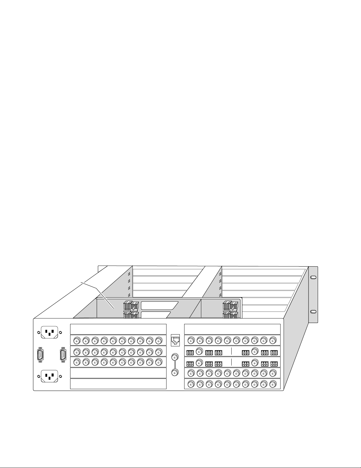
Locate a vacant slot in the rear of the 3 RU frame (Figure 1).
Figure 1. 3 RU Frame, Rear View
Rear media module slots 1 – 6Rear media module slots 7 – 12
8025-04
2 2010/2011RDA Instruction Manual
Page 9
(2)
(3)
(4)
(5)
(6)
(7)
(8)
(9)
(10)
(11)
(12)
(1)
Front Media Modules
Slots 1-12
8024 -07
2.
3.
4.
5.
Installation
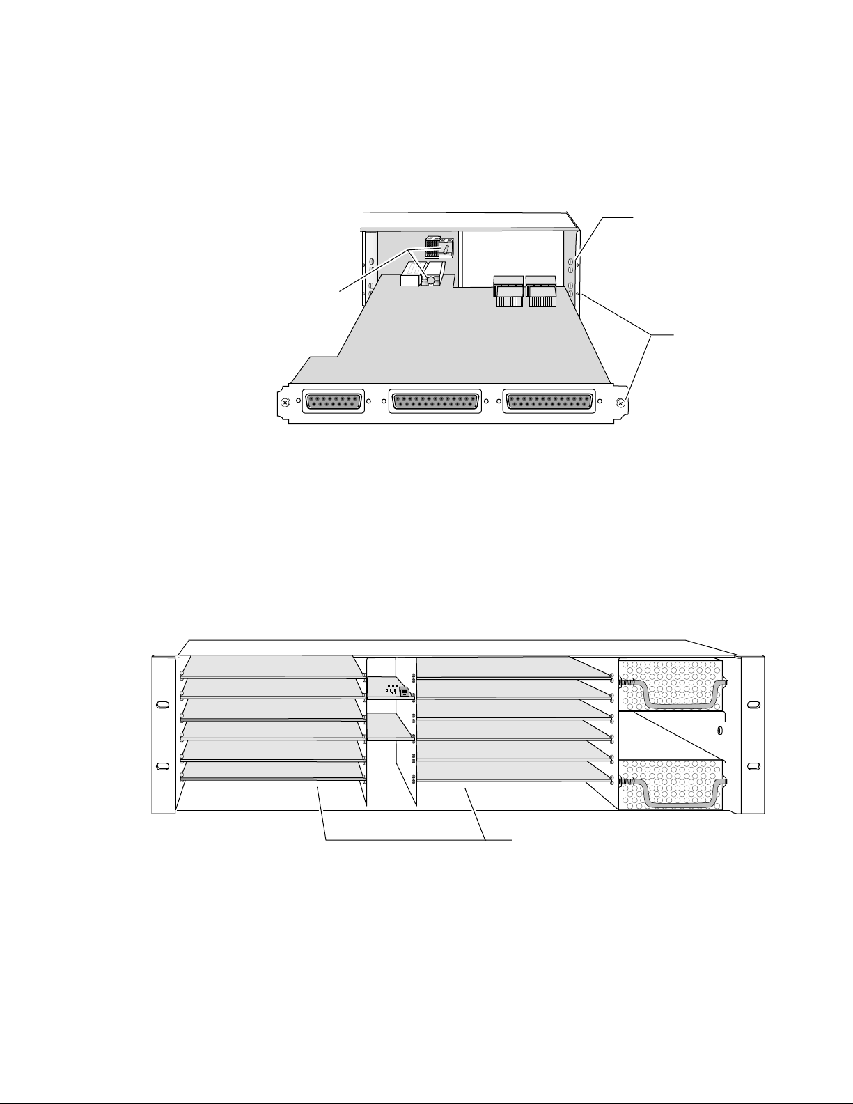
Insert the passive rear module into the vacant rear slot of the frame as
illustrated in Figure 2 (2000PRM-D shown here).
Figure 2. Installing Passive Rear Module
2000 frame (rear view)
Board edge guides
(both sides)
Alignment post
and receptacle
Screw lock
(both sides)
2000PRM–D
J3 J2 J1
AES AUDIO OUTPUTS (8)AES AUDIO OUTPUTS (8)AES AUDIO INPUTS (4)
2000PRM-D Passive Rear Module Shown
Verify that the module connector seats properly against the midplane.
Using a crossblade screwdriver, tighten the two screw locks to secure
the module in the frame.
Locate the corresponding front slot in the frame. The 3 RU frame front
view is illustrated in Figure 3.
8068_05
Figure 3. 2000 Series 3 RU Frame, Front Slots
2010/2011RDA Instruction Manual 3
Page 10

6.
7.
8.
2010/2011RDA Dual/Quad AES/EBU Reclocking DA
With the component side up, insert the front media module in the
corresponding front slot (see Figure 4).
Verify that the module connector seats properly against the midplane
and rear module connector.
Press firmly on both ejector tabs to seat the module.
Figure 4. Installing Front Media Module
2000 Frame (front view)
Alignment post and receptacle
Board edge
guides
2010/11RDA
Board edge
guides
8068-10
4 2010/2011RDA Instruction Manual
Page 11

Cabling
2010RDA COAX PRM Passive Rear Module
Installation
All cabling to the modules is done on the corresponding passive rear
module at the back of the 2000 frame. There are two versions of passive rear
modules available for the 2010RDA, the COAX PRM with 75
(Figure 5) and the 2000PRM-D with 110
Ω
D-connector I/O (Figure 6). The
Ω
BNC I/O
2011RDA-110 uses only the 2000PRM-D passive rear module.
Refer to the instructions that follow for cabling either the COAX PRM or
2000PRM-D passive rear modules for single, dual or quad mode.
Dual Mode
Single Mode
Out 4 – 8
The COAX PRM module provides ten 75
Ω
(unbalanced) BNC connectors
for single or dual operation with the 2010RDA. Refer to Figure 5 for an
illustration of the COAX PRM passive rear module.
The module must be jumpered during configuration for the desired mode
of operation. Refer to
Figure 5. COAX PRM Passive Rear Module
Set Operating Mode on page 10
CH2 In
J6J7J8J9J10 J5 J3J4 J2 J1
CH1 Out 1 – 4CH2 Out 1 – 4
Out 1 – 4
.
CH1 In
In 1
COAX
PRM
Refer to Table 1 for single and dual channel cabling.
Note At the back of this manual are overlay cards that can be placed over the BNC
connectors to identify specific single or dual connector function.
8068_06
Table 1. COAX PRM Cabling Pinouts
Connector Single Mode Dual Mode
J1 Ch 1 In Ch 1 In
J2 Ch 1 Out 1 Ch 1 Out 1
J3 Ch 1 Out 2 Ch 1 Out 2
J4 Ch 1 Out 3 Ch 1 Out 3
J5 Ch 1 Out 4 Ch 1 Out 4
2010/2011RDA Instruction Manual 5
Page 12

2010/2011RDA Dual/Quad AES/EBU Reclocking DA
Table 1. COAX PRM Cabling Pinouts
Connector Single Mode Dual Mode
J6 – Ch 2 In
J7 Ch 1 Out 5 Ch 2 Out 1
J8 Ch 1 Out 6 Ch 2 Out 2
J9 Ch 1 Out 7 Ch 2 Out 3
J10 Ch 1 Out 8 Ch 2 Out 4
2000PRM-D Passive Rear Module
AES
IN
CH3
G – +
CH1
G – +
The 2000PRM-D passive rear module with 110
Ω
D-connectors (Figure 6)
provides a single 15-pin input D-connector and two 25-pin output D-connectors for single, dual (2010RDA-110 or 2011RDA-110) or quad (2011RDA110 only) operation.
The module must be jumpered during configuration for the correct mode
of operation. Refer to
Figure 6. 2000PRM-D Passive Rear Module Backplane
J3 J2 J1
Set Operating Mode on page 10
AES AUDIO OUTPUTS (8)AES AUDIO OUTPUTS (8)AES AUDIO INPUTS (4)
.
2000PRM–D
The pinout diagram for the 2000PRM-D module is silkscreened on the component side of the front media and the 2000PRM-D passive rear module
and is shown in Figure 7.
Figure 7. 2000PRM-D Cabling Pinouts
CH4
CH3
CH2
G –11 +G –13 +G –15 + G –9 +
AES
OUT
CH1
G –1 +G – 7 +G –5 + G –3 +
AES
OUT
8068_02
1
13
8
15
– + G
– + G
CH2
CH4
1
J3
25
–16 + G –14 + G –12 + G –10 + G
CH2 (DUAL)
9
13
14
25
J2
–8 + G –6 + G –2 + G –4 + G
CH1 (DUAL)
1
14
J1
6 2010/2011RDA Instruction Manual
8068_07
Page 13

Installation
Refer to Table 2 below for a guide to 2000PRM-D passive rear module
cabling in single, dual (2010RDA-110 or 2011RDA-110) or quad
(2011RDA-110 only) mode. Note that pins numbers are given in G
(ground), – and + sequence.
Table 2. 2000PRM-D Cabling
Silkscreen
Label
J1 (25-pin D-connector)
G, –1, + 3, 2, 1 Ch 1 Out 1 Ch 1 Out 1 Ch 1 Out 1
G, –2, + 17, 18, 19 Ch 1 Out 2 Ch 1 Out 2 Ch 1 Out 2
G, –3, + 6, 5, 4 Ch 1 Out 3 Ch 1 Out 3 Ch 1 Out 3
G, –4, + 14, 15, 16 Ch 1 Out 4 Ch 1 Out 4 Ch 1 Out 4
G, –5, + 12, 11, 10 Ch 1 Out 5 Ch 1 Out 5 Ch 2 Out 1
G, –6, + 20, 21, 22 Ch 1 Out 6 Ch 1 Out 6 Ch 2 Out 2
G, –7, + 9, 8, 7 Ch 1 Out 7 Ch 1 Out 7 Ch 2 Out 3
G, –8, + 23, 24, 25 Ch 1 Out 8 Ch 1 Out 8 Ch 2 Out 4
J2 (25-pin D-connector)
G, –9, + 6, 5, 4 Ch 1 Out 9 Ch 2 Out 1 Ch 3 Out 1
G, –10, + 14, 15, 16 Ch 1 Out 10 Ch 2 Out 2 Ch 3 Out 2
G, –11, + 3, 2, 1 Ch 1 Out 11 Ch 2 Out 3 Ch 3 Out 3
G, –12, + 17, 18, 19 Ch 1 Out 12 Ch 2 Out 4 Ch 3Out 4
G, –13, + 12, 11, 10 Ch 1 Out 13 Ch 2 Out 5 Ch 4 Out 1
G, –14, + 20, 21, 22 Ch 1 Out 14 Ch 2 Out 6 Ch 4 Out 2
G, –15, + 12, 11, 10 Ch 1 Out 15 Ch 2 Out 7 Ch 4 Out 3
G, –16, + 23, 24, 25 Ch 1 Out 16 Ch 2 Out 8 Ch 4 Out 4
J3 (15-pin D-connector)
CH1 G – + 3, 2, 1 Ch 1 In Ch 1 In Ch 1 In
CH2 G – + 9, 10, 11 – Ch 2 In Ch 2 In
CH3 G – + 6, 5, 4 – – Ch 3 In
CH4 G – + 12, 13, 14 – – Ch 4 In
Pin Numbers
(G – +)
Single Mode Dual Mode Quad Mode
(2011RDA)
2010/2011RDA Instruction Manual 7
Page 14

2010/2011RDA Dual/Quad AES/EBU Reclocking DA
Power Up
The front LED indicators and configuration jumper are illustrated in
Figure 8. Upon power-up, the green PWR LED should light and the yellow
CONF LED should illuminate for the duration of module initialization.
Operation Indicator LEDs
With valid input signals connected, the green PWR LED and the green
LOCK LED 1–4 should be on for each channel.
Figure 8. Operation Indicator LEDs
FAULT
COMM CONF PWR
FAULT (red)
COMM (yellow)
LOCK1
LOCK2 LOCK3 LOCK4
CONF (yellow)
PWR (green)
LOCK 1 (green)
LOCK 2 (green)
LOCK 3 (green) 2011RDA only
LOCK 4 (green) 2011RDA only
8068_03
8 2010/2011RDA Instruction Manual
Page 15

A red FAULT LED indicates an error situation and, with the other LEDs,
can indicate the operational conditions presented in Table 3. The table
describes signal output and LED indications for various input/reference
combinations and user settings.
Table 3. Indicator LEDs and Conditions Indicated
LED Indication Condition
FAULT
(red)
COMM
(yellow)
CONF
(yellow)
PWR
(green)
LOCK 1
(green)
LOCK 2
(green)
LOCK 3
(green)
LOCK 4
(green)
Off Normal operation.
On continuously Module has detected an internal fault.
Flashing Reference input is faulty or not present.
Off No activity on frame communication bus.
Long flash Location Command received by the module from a remote control system.
Short flash Activity present on the frame communication bus.
Off Module is in normal operating mode.
On continuously
Flashing Indicates rate of change of paddle-controlled analog setting.
Off No power to module or module’s DC/DC converter failed.
On continuously Normal operation, module is powered.
Off Module does not detect a valid AES in reference signal on channel 1.
On continuously Valid AES in reference signal is present on channel 1 and module is locked to it.
Off Module does not detect a valid AES in reference signal on channel 2.
On continuously Valid AES in reference signal is present on channel 2 and module is locked to it.
Off Module does not detect a valid AES in reference signal on channel 3.
On continuously Valid AES in reference signal is present on channel 3 and module is locked to it.
Off Module does not detect a valid AES in reference signal on channel 4.
On continuously Valid AES in reference signal is present on channel 4 and module is locked to it.
Module is initializing, changing operating modes or updating firmware. Simultaneous CONF
and FAULT LEDs on indicate FPGA load error.
Power Up
Note LOCK 3 and LOCK 4 LEDs will only be active on the 2011RDA-110 module.
2010/2011RDA Instruction Manual 9
Page 16

2010/2011RDA Dual/Quad AES/EBU Reclocking DA
Configuration and Monitoring
Configuring the 2010/2011RDA consists of setting the operating mode to
single, dual or quad input/output with an on-board jumper.
Local Onboard Module Configuration
The 2010/2011RDA module is configured locally using the jumper shown
in Figure 9. The CONF LED indicates status of the configuration process.
Figure 9. Module Configuration Switches and LEDs
FAULT
COMM CONF PWR
Configuration LED
LOCK1
LOCK2 LOCK3 LOCK4
JP5
Set Operating Mode
Set jumper JP5 for one of the following operating modes:
2010RDA DUAL AES/EBU RECLOCKING DA
2011RDA QUAD
1
JP5
SINGLE
6
DUAL
QUAD
8068_03
Single (pins 1/2)
■
1 input by 8 outputs (COAX PRM), or
■
1 input by 16 outputs (2000PRM-D).
Dual (pins 3/4)
■
2 inputs by 4 outputs (COAX PRM), or
2 inputs by 8 outputs (2000PRM-D).
■
Quad (pins 5/6)
4 inputs by 4 outputs (2011RDA-110 module only)
■
10 2010/2011RDA Instruction Manual
Page 17

Remote Configuration and Monitoring
Monitoring of the 2010/2011RDA can be performed remotely using the
2000NET interface (see Figure 10). This section describes the GUI access to
the module configuration functions. Refer to the 2000NET Network Interface Module Instruction Manual for information on setting up and operating the 2000 frame network.
Remote Configuration and Monitoring
Note
The physical appearance of the menu displays shown in this manual represent the use of a particular platform, browser and version of 2000NET
module software. They are provided for reference only. Displays will differ
depending on the type of platform and browser you are using and the version
of the 2000NET software installed in your system.
The 2000 modules can be addressed by clicking on a specific module icon
in the frame status display or on a module name or slot number in the link
list on the left.
Figure 10. 2000NET GUI
The Links section lists the frame and its current modules. The selected link's Status
page is first displayed and the sub-list of links for the selection is opened. The sub-list
allows you to select a particular information page for the selected device.
Content display section displays the information page
for the selected frame or module (frame slot icons are also
active links).
8026-08
2010/2011RDA Instruction Manual 11
Page 18

2010/2011RDA Dual/Quad AES/EBU Reclocking DA
Module Configuration Displays
The 2000 GUI provides the following links and displays for the
2010/2011RDA module (Figure 11):
■
Module Configuration displays showing status and slot configuration
information (location and user assigned names),
Input Status Output Mode display, and
■
■
Software Update display.
The Module Configuration displays operate in the same manner for all
remote controllable 2000 modules. Refer to the 2000NET manual for more
information on these displays. Some functions listed may not be supported
by a particular module. These will be indicated as not supported.
Figure 11. 2010/2011RDADisplay Links
Software Update Display
The Software Update display allows you to download new software versions for the module. Refer to the 2000NET manual and the Grass Valley
Group web site at http://www.grassvalleygroup.com for complete details
and new software versions.
Input Status Output Mode Display
This section discusses the Input Status Output Mode display available to
monitor the 2010/2011RDA module status remotely.
12 2010/2011RDA Instruction Manual
Page 19

Use
This
Link
Remote Configuration and Monitoring
INPUT STATUS OUTPUT MODE
The
display (Figure 12) provides the following
status reporting items for the module:
■
■
indicates whether the on-board jumper is configured for
MODE
or
DUAL
REAR MODULE ID
PRM-COAX
PRM (
output mode. (Refer to Set Operating Mode on page 10 .)
QUAD
indicates whether the 2000PRM-D (
) passive rear module is installed. (Refer to 2000PRM-D
PRM-D
) or COAX
Passive Rear Module on page 6 or 2010RDA COAX PRM Passive Rear
Module on page 5 .)
SINGLE
,
2010RDA Module
installed
Ouput mode
Type of rear
module installed
Input impedance
Channel lock status
Sample rate status
■
INPUT IMPEDANCE
module installed as
■
CHANNEL LOCK
indicates the input impedance of the passive rear
75 OHM
(COAX PRM) or
110 OHM
indicates whether each channel is
erence signal is present and module is locked to it) or
(module does not detect a valid AES reference signal).
■
SAMPLE RATE
each channel as one of the following:
96K
or
Figure 12. 2010/2011RDA Input Status/Output Mode Display
indicates the current input sample rate being detected by
OUT OF RANGE, 32K, 44.1K, 48K, 88.2K
.
(2000PRM-D).
LOCKED
(valid AES ref-
UNLOCKED
2011RDA Module
with PRM-D passive
rear module installed
and set to Quad mode
D
2010/2011RDA Instruction Manual 13
Page 20

2010/2011RDA Dual/Quad AES/EBU Reclocking DA
Specifications
Table 4. 2010/2011RDA Specifications
Parameter Value
AES/EBU Inputs (2010RDA COAX PRM)
Signal type AES3id – 1992
Number of inputs 2 (jumper selectable for single or dual)
Connector type 75 Ω BNC (COAX PRM passive rear module)
Common mode range ± 10 V
Differential voltage range 200 mV to 12 V p-p
Sample rate 32 kHz, 44.1 kHz, 48 kHz, or 96 kHz
Input return loss >15 dB (100 kHz – 10 MHz)
Maximum jitter < 6 ns RMS
AES Output (2010RDA COAX PRM)
Signal type AES3id – 1992
Number of outputs 8
Connector type 75 Ω BNC (COAX PRM passive rear module)
Output level Unbalanced 1 V ± 0.1 p-p terminated in 75
Rise/fall time 30 to 44 ns (across 75 Ω load)
Sample rate 32 kHz, 44.1 kHz, 48 kHz, or 96 kHz
Input return loss >15 dB (100 kHz – 6 MHz)
Maximum jitter < 6 ns RMS
AES/EBU Inputs (2010/2011RDA-110 2000PRM-D)
Signal type AES3 – 1992 (transformer coupled)
Number of inputs 4 (jumper selectable for single, dual or quad)
Connector type 15-pin 110
Common mode range ± 10V
Differential voltage range 200 mV to 12 V p-p
Sample rate 32 kHz, 44.1 kHz, 48 kHz, or 96 kHz
Input return loss >15 dB (100 kHz – 10 MHz)
Maximum jitter < 6 ns RMS
AES Output (2010/2011RDA-110 2000PRM-D)
Signal type AES3id – 1992 (transformer coupled)
Number of outputs 16
Connector type 25-pin 110 Ω D-connector (2000PRM -D)
Output level Balanced -2 V to 7 V p-s (terminated in 110 Ω)
Rise/fall time 5 to 30 ns (across 110 Ω load)
Sample rate 32 kHz, 44.1 kHz, 48 kHz, or 96 kHz
Input return loss >15 dB (100 kHz – 6 MHz)
Maximum jitter < 6 ns RMS
Performance
Module insertion to operation < 1.5 seconds
Ω
Ω D-connector (2000PRM-D)
14 2010/2011RDA Instruction Manual
Page 21

Table 4. 2010/2011RDA Specifications - (continued)
Parameter Value
DC offset <±1 mV
Electrical length (delay) 560 ns
Static withstand 5 kV (330 Ω, 150 pF) any input or output
Environmental
Frame temperature range 0 to 40° C
Operating humidity range 0 to 90% non-condensing
Non-operating temperature -10 to 70° C
Mechanical
Frame type 2000 Series
Power Requirements
Supply voltage +24 V
Power consumption <3.3 Watts
Specifications
2010/2011RDA Instruction Manual 15
Page 22

2010/2011RDA Dual/Quad AES/EBU Reclocking DA
Service
The 2010/2011RDA modules make extensive use of surface-mount technology and programmed parts to achieve compact size and adherence to
demanding technical specifications. Circuit modules should not be serviced in the field unless directed otherwise by Customer Service.
If your module is not operating correctly, proceed as follows:
■ Check frame and module power. If power is not present, check the fuse
on the +24 V input to the module as illustrated in Figure 13.
■ Check for presence and quality of input signals.
■ Verify that source equipment is operating correctly.
■ Check cable connections.
Figure 13. Location of Module Fuse
Fuse: 2 A FAST, 125 V
F1
8023_08
Refer to Figure 8 for the location of PWR LED and Table 3 on page 9 for
proper LED indications.
If the module is still not operating correctly, replace it with a known good
spare and return the faulty module to a designated Grass Valley repair
depot. Call your Grass Valley representative for depot location.
Refer to the Contacting Grass Valley Group at the front of this document for
the Grass Valley Customer Support Information number.
16 2010/2011RDA Instruction Manual
Page 23

Functional Description
_
e
e
The functional description for the 2010RDA and the 2011RDA-110 are
nearly identical except for the passive rear modules and the number of
audio channels available. Refer to the block diagram for the type of module
you are using. The block diagram in Figure 14 represents the 2010RDA
with the COAX PRM 75 Ω passive rear module. The block diagram in
Figure 15 represents the 2010RDA-110 and the 2011RDA-110 with the
2000PRM-D 110 Ω passive rear module.
The 2010/2011RDA modules reclock and distribute AES/EBU digital
audio. The 2010RDA has two independent streams of video and the
2011RDA-110 has four independent streams. The modules are configured
with jumpers to operate in single, dual or quad (2011RDA-110 only) mode.
Figure 14. 2010RDA with COAX PRM
Functional Description
PWR LED
FAULT LED
COMM LED
CONF LED
LOCK 2 LED
LOCK 1 LED
Controller
2010RDA Module
Power Supply
FPGA
Routing and Control
Processor
Configuration
AES Receiver
AES Receiver
+5V
+3.3V
Jumper
+24V
CH 2
CH 1
Midplane
COAX PRM
J10
J9
J8
J7
J5
J4
J3
J2
J6
J1
CH 2
Out
Dual
Mode
CH 1
Out
Singl
Mod
CH 1
Out
Dual
Mode
01
8068
2010/2011RDA Instruction Manual 17
Page 24

2010/2011RDA Dual/Quad AES/EBU Reclocking DA
AES Receivers
Each channel of AES3 audio is fed to the modules through an isolation
transformer into a crystal receiver IC where the data is reclocked by means
of a phase-locked-loop (PLL). Each AES Receiver controls the LOCK LEDs
which indicate when the receiver IC is locked to an incoming data stream.
The reclocked signal is then fed to the FPGA for routing and control.
Figure 15. 2010RDA-110/2011RDA-110 with 2000PRM-D
PWR LED
FAULT LED
COMM LED
Controller
CONF LED
LOCK 4 LED (2011RDA)
LOCK 3 LED (2011RDA)
2010RDA Module
Power Supply
FPGA
Routing and Control
Processor
Configuration
AES Receiver
AES Receiver
+5V
+3.3V
Jumper
+24V
CH 4 (2011RDA)
CH 3 (2011RDA)
Output
Driver
Output
Driver
Output
Driver
Output
Driver
Midplane
2000PRM–D
J1
25-pin D-Connector
J2
25-pin D-Connector
J3
LOCK 2 LED
LOCK 1 LED
AES Receiver
AES Receiver
CH 2
15-pin D-Connector
CH 1
18 2010/2011RDA Instruction Manual
_
Page 25

Routing and Control FPGA
The signals from the AES receiver ICs are applied to the Routing and
Control FPGA. The signal routing is determined by the setting of the onboard configuration jumper at the front of the module. After processing,
the signals are embedded into an AES stream and applied to the Output
Drivers.
The Routing and Control section also drives the front panel LEDs and interfaces to the Controller section.
Controller
The Controller interfaces with the Routing and Control FPGA, the
EEPROM and the 2000 Frame Bus. The Controller also provides the FPGA
code that is downloaded to the FPGA during boot-up.
The Controller section handles local control and monitoring, as well as
remote control and monitoring via the frame bus (when an 2000NET
module is installed in the frame). Module settings are stored in the
EEPROM for power up recall.
Functional Description
Power Supply
Power is fed from +24 V rails of the frame’s switching power supply. Each
stage of the module receives its own, separate, highly regulated and filtered
power source.
2010/2011RDA Instruction Manual 19
Page 26

2010/2011RDA Dual/Quad AES/EBU Reclocking DA
20 2010/2011RDA Instruction Manual
Page 27

Index
Numerics
2000NET module 12
2000PRM-D passive rear module
cabling
2010RDA
features
specifications 14
2011RDA
features
specifications 14
6
1
1
C
COAX PRM passive rear module
cabling
COMM LED 9
CONF (configuring) LED 9, 10
configuration
on-board
remote 11
5
10
D
dual mode 10
L
LOCK LEDs 8, 9
M
media module 2
installation 4
midplane 4
N
network 11
O
operational conditions
LED indications
9
P
passive rear module 2
installation 2
power requirements 15
PWR LED 8, 9
F
FAULT LED 9
frame status display 11
frame, 3RU 2
fuse 16
Q
quad mode 10
R
repair depot 16
G
S
GUI 11, 12
single mode 10
software update 12
I
Input Status Output Mode display 13
installation 2
2010/2011RDA Instruction Manual Index-1
T
troubleshooting 16
Page 28

Index-2 2010/2011RDA Instruction Manual
 Loading...