

Page 1
2000GEN
GENLOCK TIMING MODULE
Instruction Manual
SOFTWARE VERSION 1.0.0
071817201
AUGUST 2003
Page 2

Contacting Grass Valley
Region Voice Fax Address Web Site
North America (800) 547-8949
Support: 530-478-4148
Pacific Operations +852-2585-6688
Support: 852-2585-6579
U.K., Europe, Asia, Middle East +44 1753 218 777 +44 1753 218 757
France +33 1 45 29 73 00
Germany +49 221 1791 234 +49 221 1791 235
Copyright © Thomson Broadcast and Media Solutions All rights reserved.
Grass Valley Web Site
Sales: (530) 478-3347
Support: (530) 478-3181
+852-2802-2996
Grass Valley
P.O. Box 599000
Nevada City, CA 959597900 USA
www.thomsongrassvalley.com
The www
Online User Documentation
.thomsongrassvalley.com web site offers the following:
— Current versions of product catalogs, brochures,
data sheets, ordering guides, planning guides, manuals, and release notes
in .pdf format can be downloaded.
FAQ Database
— Solutions to problems and troubleshooting efforts can be
found by searching our Frequently Asked Questions (FAQ) database.
Software Downloads
— Software updates, drivers, and patches can be down-
loaded.
2 2000GEN Instruction Manual
Page 3

Contents
2000GEN Genlock Timing Module
Introduction . . . . . . . . . . . . . . . . . . . . . . . . . . . . . . . . . . . . . . . . . . . . . . . . . . . . . . . . . . . 5
Installation . . . . . . . . . . . . . . . . . . . . . . . . . . . . . . . . . . . . . . . . . . . . . . . . . . . . . . . . . . . . 6
Module Placement in the Frame . . . . . . . . . . . . . . . . . . . . . . . . . . . . . . . . . . . . . . . . 6
Cabling . . . . . . . . . . . . . . . . . . . . . . . . . . . . . . . . . . . . . . . . . . . . . . . . . . . . . . . . . . . . . 7
Reference Inputs. . . . . . . . . . . . . . . . . . . . . . . . . . . . . . . . . . . . . . . . . . . . . . . . . . . . 7
Power Up . . . . . . . . . . . . . . . . . . . . . . . . . . . . . . . . . . . . . . . . . . . . . . . . . . . . . . . . . . . . . 8
Operation Indicator LEDs . . . . . . . . . . . . . . . . . . . . . . . . . . . . . . . . . . . . . . . . . . . . . 8
Remote Control and Monitoring. . . . . . . . . . . . . . . . . . . . . . . . . . . . . . . . . . . . . . . . . 10
Module Links and Configuration Displays . . . . . . . . . . . . . . . . . . . . . . . . . . . . . . 11
Status Display. . . . . . . . . . . . . . . . . . . . . . . . . . . . . . . . . . . . . . . . . . . . . . . . . . . . . . . 12
Genlock Status Display. . . . . . . . . . . . . . . . . . . . . . . . . . . . . . . . . . . . . . . . . . . . . . . 12
Settings Display . . . . . . . . . . . . . . . . . . . . . . . . . . . . . . . . . . . . . . . . . . . . . . . . . . . . . 13
Slot Configuration . . . . . . . . . . . . . . . . . . . . . . . . . . . . . . . . . . . . . . . . . . . . . . . . . . . 14
Locate Module . . . . . . . . . . . . . . . . . . . . . . . . . . . . . . . . . . . . . . . . . . . . . . . . . . . . 14
Slot Identification. . . . . . . . . . . . . . . . . . . . . . . . . . . . . . . . . . . . . . . . . . . . . . . . . . 14
Slot Memory . . . . . . . . . . . . . . . . . . . . . . . . . . . . . . . . . . . . . . . . . . . . . . . . . . . . . . 15
Hardware Switch Controls. . . . . . . . . . . . . . . . . . . . . . . . . . . . . . . . . . . . . . . . . . 15
Slot SNMP Trap Reports. . . . . . . . . . . . . . . . . . . . . . . . . . . . . . . . . . . . . . . . . . . . 15
Software Update Display . . . . . . . . . . . . . . . . . . . . . . . . . . . . . . . . . . . . . . . . . . . . . 16
Specifications . . . . . . . . . . . . . . . . . . . . . . . . . . . . . . . . . . . . . . . . . . . . . . . . . . . . . . . . . 17
Service. . . . . . . . . . . . . . . . . . . . . . . . . . . . . . . . . . . . . . . . . . . . . . . . . . . . . . . . . . . . . . . 18
Power-up Diagnostics Failure . . . . . . . . . . . . . . . . . . . . . . . . . . . . . . . . . . . . . . . . . 18
Troubleshooting. . . . . . . . . . . . . . . . . . . . . . . . . . . . . . . . . . . . . . . . . . . . . . . . . . . . . 18
Module Repair . . . . . . . . . . . . . . . . . . . . . . . . . . . . . . . . . . . . . . . . . . . . . . . . . . . . . . 18
Functional Description . . . . . . . . . . . . . . . . . . . . . . . . . . . . . . . . . . . . . . . . . . . . . . . . . 19
Inputs and Outputs . . . . . . . . . . . . . . . . . . . . . . . . . . . . . . . . . . . . . . . . . . . . . . . . . . 19
Microcontroller . . . . . . . . . . . . . . . . . . . . . . . . . . . . . . . . . . . . . . . . . . . . . . . . . . . . . 19
Index
2000GEN Instruction Manual 3
. . . . . . . . . . . . . . . . . . . . . . . . . . . . . . . . . . . . . . . . . . . . . . . . . . . . . . . . . . . . . . . . . . . . . . 21
Page 4

Contents
4 2000GEN Instruction Manual
Page 5

2000GEN Genlock Timing Module
Introduction
The 2000GEN Genlock Timing Module locks to reference black burst and
provides clock and pulse timing references for the applicable modules in
Kameleon Series frames.
Key features of the 2000GEN module include:
• Support for NTSC, PAL-B reference input signal,
•A low-jitter 27 MHz reference clock generator,
•A generated common reference pulse stream containing:
•Reference field pulse,
• Frame bit,
•Color-frame bit,
•AES 5 frame sequence bits,
•Differential LVDS (low voltage differential signaling) lines that distribute signals to each front module slot,
•Reference blackburst locked with burst lock PLL as default, and
•Remote control and monitoring support.
2000GEN Instruction Manual 5
Page 6
1.
2.
3.
Installation
Installation
Module Placement in the Frame
The 2000GEN module can be plugged in and removed from a Kameleon
Series frame with power on. When power is applied to the module, LED
indicators reflect the initialization process (see
Power Up
on page 8).
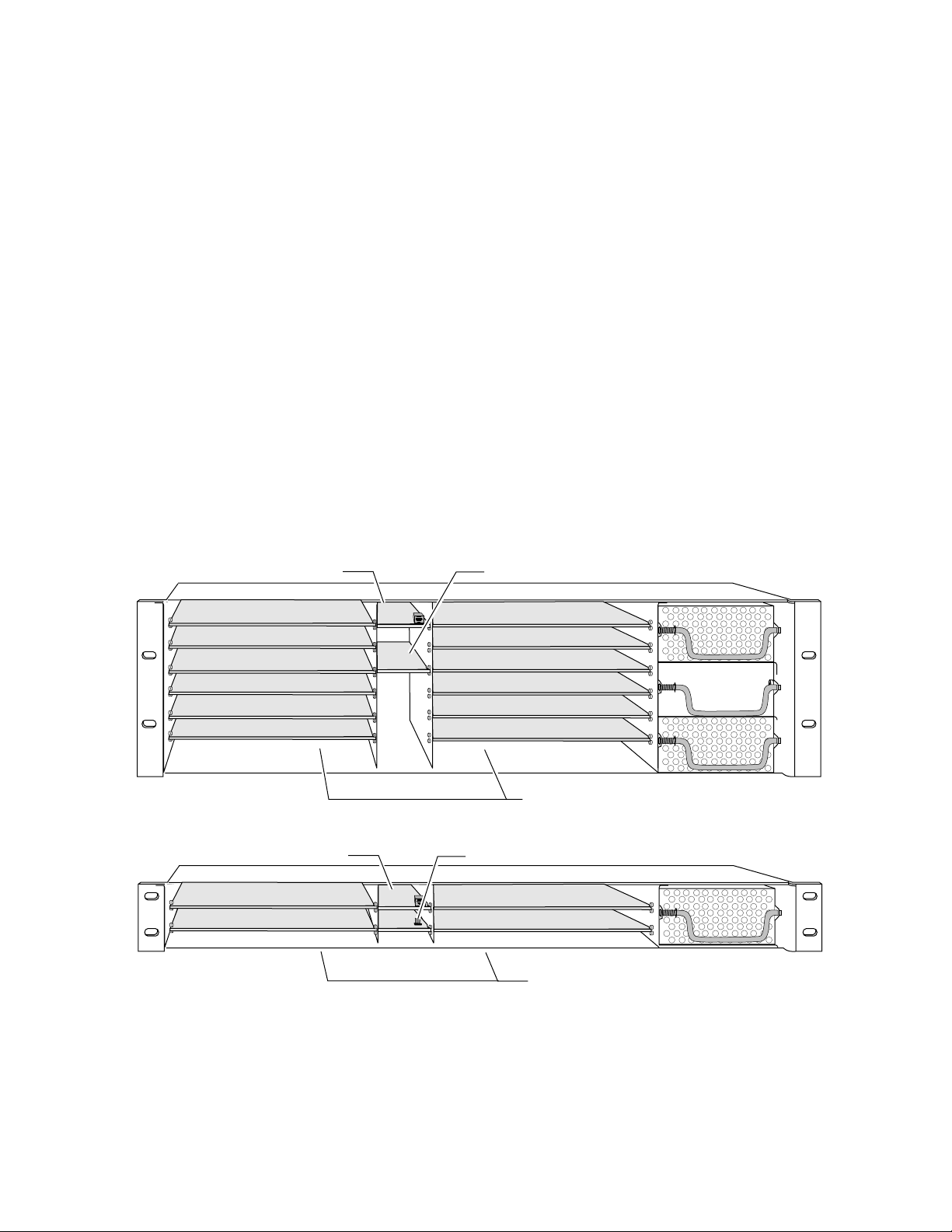
There are six cell locations in central control module section of the 3 RU
frame to accommodate network and reference modules. The 2000GEN
module plugs into Slot 15 (see Figure 1). The 1 RU frame has two central
control module slots. Slot 6 is used for the 2000GEN module.
Install the module by inserting it into the appropriate slot of the frame.
Verify that the module connector seats properly against the midplane
connector.
3 RU Frame
1 RU Frame
Press the module ejector tab to seat the module in the slot.
Figure 1. 2000GEN Module Frame Slots
Network Slot (13)
(1)
(2)
(3)
(4)
(5)
(6)
Network Slot (5) Genlock Timing Slot (6)
(1)
(2)
(13)
(15)
(5)
(6)
Genlock Timing Slot (15)
(7)
(8)
(9)
(10)
(11)
(12)
Front Media Slots (1-12)
(3)
(4)
8172-01
8172-03
Front Media Slots (1-4)
6 2000GEN Instruction Manual
Page 7
Cabling
3 RU Frame
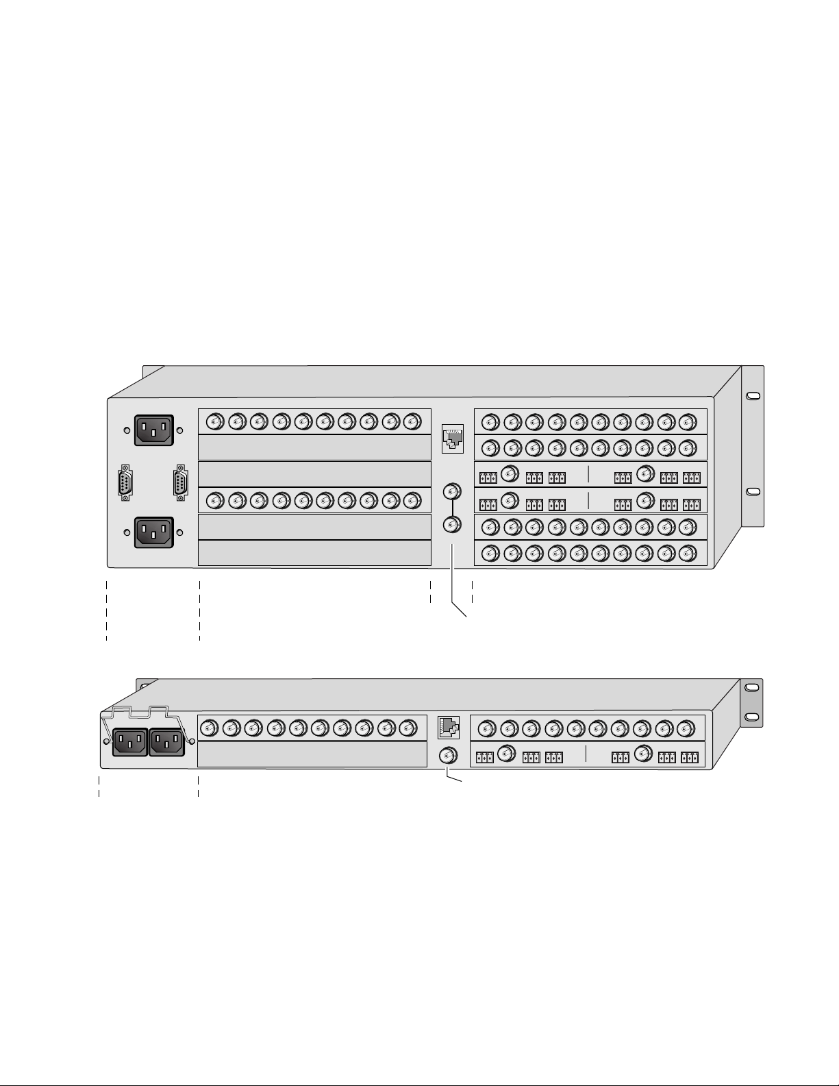
Cabling to the 2000GEN module is done on the BNCs on the rear of the
frame. Refer to Figure 2 for a detailed illustration of the rear connections
referenced below.
Reference Inputs
The 2000GEN will accept any of the video standards listed in the Input
specifications in Table 1 on page 17. Connect a video input to the Reference
BNC. In the 3 RU frame, terminate the looping connector if the signal is not
looped to other equipment.
Figure 2. 2000GEN Input Connectors
Installation
Power, frame
configuration,
& frame health
connections
1 RU Frame
Power connections
Media section
rear slots 7-12
Media section
rear slots 3-4
Reference
Loopthrough Input
1
3
J101
J102
2
4
Terminating
Reference
Input
Media section
rear slots 1-6
Media section
rear slots 1-2
8172-07
8172-06
2000GEN Instruction Manual 7
Page 8
Power Up
Power Up
Operation Indicator LEDs
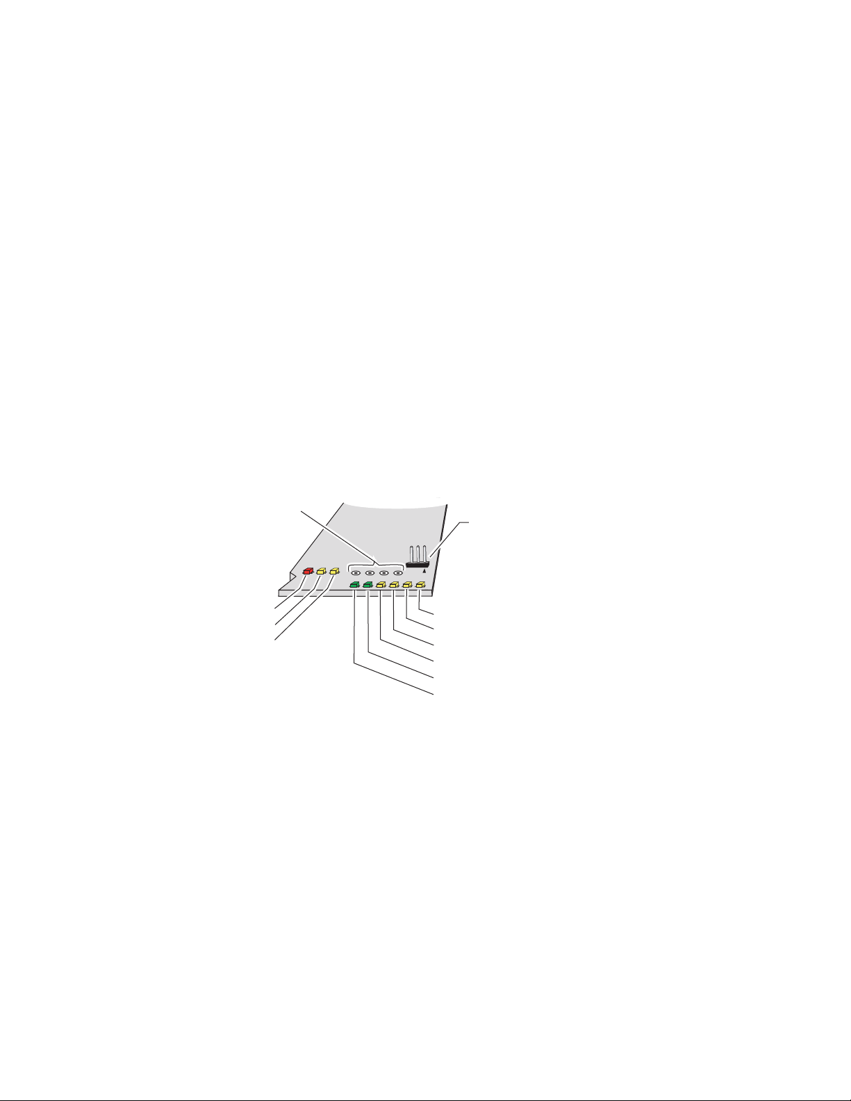
The on-board LED indicators are illustrated in Figure 3. Upon power-up,
the green PWR LED should light and the yellow CONF LED should illuminate for the duration of module initialization.
After initialization, the green on-board PWR LED should light to indicate
correct power is present. Power can be measured at the indicated
testpoints.
Set the jumper at J8 to
should be off). When remote configuration is complete, the jumper can be
set to local to lock out any further changes but still allow remote monitoring of the module if desired.
Refer to Table 1 on page 9 to see a complete list of possible operating con-
ditions and the resulting indicator status.
Figure 3. LEDs and Configuration Switches
Testpoints
+5V, +3.3V, +2.5V, -5V
FAULT red
Communication (COMM) yellow
Configuration (CONF) yellow
Remote
during configuration (LOCK OUT LED
Remote control
lockout jumper, J8
(Local = Pins 1 and 2,
Remote = Pins 2 and 3)
8172-02
Remote LOCK OUT yellow
PAL M yellow
PAL B yellow
NTSC yellow
Signal Lock LOCKED green
Power OK (PWR) green
8 2000GEN Instruction Manual
Page 9

Table 1 describes the meaning of the various states for the LED indications
on the front of the module (from left to right).
Table 1. Indicator LEDs and Conditions Indicated
LED Indication Condition
Off Module functioning properly
FAULT (red)
COMM (yellow)
CONF (yellow)
PWR (green)
LOCKED (green)
NTSC (yellow)
PAL -B (yellow)
PAL-M (yellow)
LOCK OUT (yellow)
On continuously Module has detected internal fault
Long flash Selected reference signal missing
Off No activity on frame bus
Long flash Locate Module command received by the module from a remote control system
Short flash Activity present on the frame communication bus
Off Module is in normal operating mode
On continuously Module is initializing, changing operating modes or updating firmware
Off No power to module or module’s DC/DC converter failed
On continuously Normal operation, module is powered
Off Signal phase unlocked
On continuously Signal phase locked
Off NTSC mode not selected
On continuously NTSC mode selected
Off PAL-B mode not selected
On continuously PAL-B mode selected
Off PAL-M mode not selected (currently not used)
On continuously PAL-M mode selected (currently not used)
Off Jumper J8 is in the Remote position
On continuously
Jumper J8 is in the Local position, remote module configuration is locked out, monitoring is still enabled
Power Up
2000GEN Instruction Manual 9
Page 10

Remote Control and Monitoring
Remote Control and Monitoring
The 2000GEN has no on-board user configuration requirements. There is a
jumper, J8 — LOCAL/REMOTE , on the front of the module (Figure 3 on
page 8) for enabling or disabling remote control.
2000GEN control and monitoring can be performed remotely using the
2000NET interface (see Figure 4). This section describes the GUI access to
the module configuration and monitoring functions. Refer to the 2
Network Interface Module Instruction Manual
and operating the Kameleon frame network.
000NET
for information on setting up
Note
The 2000 modules can be addressed by clicking on a specific module icon
in the frame status display or on a module name or slot number in the link
list on the left.
Figure 4. 2000NET GUI
The Links section lists the frame and its current modules. The selected link's Status
page is first displayed and the sub-list of links for the selection is opened. The sub-list
allows you to select a particular information page for the selected device.
The physical appearance of the menu displays shown in this manual represent the use of a particular platform, browser and version of 2000NET
module software. They are provided for reference only. Displays will differ
depending on the type of platform and browser you are using and the version
of the 2000NET software installed in your system.
Content display section displays the information page
for the selected frame or module (frame slot icons are also
active links).
Refresh button for manual
refresh of page
Online Manual Link
8046-13 r1
'
10 2000GEN Instruction Manual
Page 11

To navigate to one of the device’s pages click on any of the device’s sub-list
of links. This will update the content display to the right.
Remote Control and Monitoring
Note
Using the web browser’s reload function will always return you to the
Frame Status page. To refresh a particular page, always click on that page’s
Refresh
The Online Manual Link will open a .PDF version of the appropriate
instruction manual if you have set up an Online Manual Server as
described in the 2000NET manual.
To update status, HTML pages must be manually refreshed by clicking on the
Refresh button. Changes made at the frame or from other browsers on the
network will not be displayed until the page is refreshed.
button to the right of the page name.
Module Links and Configuration Displays
The 2000 GUI provides the following links and displays for the 2000GEN
module (Figure 5):
• Status display showing overall module status,
•Genlock Status display showing genlock status,
• Settings display for configuring the module parameters,
• Slot Config display showing slot identification and status reporting,
and
• Software Update display.
The Module Configuration displays operate in the same manner for all
remote controllable 2000 modules. Refer to the 2000NET manual for more
information on these displays. Some functions listed may not be supported
by a particular module. These will be indicated as not supported.
Figure 5. 2000GEN Display Links
2000GEN Instruction Manual 11
Page 12

Remote Control and Monitoring
Status Display
Use
This
Link
The Status display (Figure 6) shows status of the input and output signal
status and module properties (part and serial number, and software, hardware and firmware version).
Figure 6. 2000GEN Status Display
Use
This
Link
Genlock Status Display
The Genlock Status display (Figure 7) shows the genlock standard selected
and lock status of the reference input and color and AES frame.
Figure 7. Genlock Status Display
12 2000GEN Instruction Manual
Page 13

Use
This
Link
Settings Display
The Settings display (Figure 8) provides controls for selecting the video
standard, the genlock mode and for making adjustments to the input
timing stream from the external reference.
The following configuration parameters are provided for the module:
Remote Control and Monitoring
•Use
Standard Select
to choose the video standard as either
NTSC
or
The input video standard is not auto-sensing.
• Set the
Genlock
nected to the reference BNC,
control to lock the module to the external reference con-
Enable
or
Free Run
(not locked to external
reference).
• Set the
Frame Offset
to shift the input timing stream by frames in reference to the input signal color framing (NTSC = 0–1, PAL-B = 0–3,
Default = 0).
• Set the
Line Offset
to shift the input timing stream by lines up to one full
frame (NTSC = 0–524, PAL-B = 0–624, Default = 0).
• Set the
Pixel Offset
to shift the input timing stream by pixels up to one full
line (NTSC = 0–857.5, PAL-B = 0–863.5, Default = 0).
• Set the
AES Frame Offset
to shift the AES marker in the timing stream by
VFrames for NTSC only (NTSC = 0–4, Default = 0). PAL-B is not adjustable (always 0).
• Select
Recall Defaults
to recall preset factory defaults for the selected stan-
dard.
Figure 8. 2000GEN Settings Display
PAL-B
.
Set video standard
Set Genlock mode
Set Line Offset
Set Frame Offset
Set Pixel Offset
Set AES Frame Offset
Recall factory defaults
2000GEN Instruction Manual 13
Page 14

Remote Control and Monitoring
Slot Configuration
The Slot Config display (Figure 9) allows you to do the following:
•Activate/deactivate the module locator function,
Use
This
Link
Locate Module
•Type a specific name for the module and the input signal, and
•Report and enable/disable SNMP reporting for the slot.
When enabled, the
CONF LEDs three times on, then a long off period, to make the module
easy to locate in the frame.
Slot Identification
In the
identifying name for the module and a name to identify the input signal.
The assigned names are stored on the 2000GEN module and travel with the
module if it is moved to another frame.
Figure 9. 2000GEN Slot Config Screen
Enable/disable module
locator function
Name the module slot
Slot Identification
Locate Module
Name and Input Signal Name fields, you can type an
function blinks the yellow COMM and
Name the input signal
Check box to restore saved config
when new module installed
Learn module configuration
to this slot
Read-only status of 2000NET
module hardware settings
necessary for enabling
SNMP Trap Reports
Enable/disable specific
SNMP reports for the slot
Read-only severity level
assigned to each event
14 2000GEN Instruction Manual
Page 15

Slot Memory
The slot configuration for each media module is automatically saved periodically (once an hour) to the 2000NET module in that frame. You may also
select the
ration for this slot. The configuration is saved on the 2000NET module. If
the 2000NET module is removed or powered down, the stored configurations are not saved.
Learn Module Config
Remote Control and Monitoring
button at any time to save the current configu-
When the
saved to this slot is saved as slot memory. When the current module is
removed and another module of the same type is installed, the configuration saved to the 2000NET module will be downloaded to the new module.
The box must be checked before the current module with the saved configuration is removed.
Restore upon Install
Hardware Switch Controls
This section is a read-only status report of 2000NET module switch settings
for Module Status Reporting and Asynchronous Status Reporting. These
functions must be enabled on the 2000NET module for the following Slot
SNMP Trap Reports to function.
Slot SNMP Trap Reports
This section is displayed only when the SNMP Agent software has been
installed on the 2000NET module (refer to the 2000NET Instruction Manua l
for installation instructions). Slot SNMP traps can be enabled only when
the hardware switches for Module Fault reporting and Asynchronous
Status reporting are in enabled on the 2000NET module (dipswitch S1
segment 7 and dipswitch S2 segment 1).
box has been checked, the current configuration
The enabled SNMP traps will be reported to any SNMP manager that is
identified as an SNMP Report Destination in 2000NET configuration. Trap
severity is read-only hard-coded information that is interpreted and
responded to by the SNMP Manager software configuration.
2000GEN Instruction Manual 15
Page 16

Remote Control and Monitoring
Software Update Display
The Software Update display (Figure 10) allows you to download new software versions for the module. Refer to the 2000NET manual and the Grass
Valley web site at http://www.thomsongrassvalley.com for complete
Use
This
Link
details on software downloading and new software versions.
Figure 10. 2000GEN Software Update Display
16 2000GEN Instruction Manual
Page 17

Specifications
Specifications
Table 1. 2000GEN Specifications
Parameter Value
Input
Connector type 75
Input impedance High impedance to meet return loss with terminating frame assembly
Signal type NTSC, PAL-B standard complying blackburst video
Return loss > 40 dB up to 10 MHz
Equalization None
CMRR None
Hum rejection > 40 dB on a maximum of 1 V p-p of 60 Hz hum
Input Locking Conditions
Input signal minimum S/N ratio > 40 dB
Signal level 300 mV p-p ± 6 dB of sync tip portion
SCH error range ± 45 degrees for NTSC and PAL-B
Timebase error range ± 15 ppm over temperature range
AES framing detection Meets SMPTE 318 standard
Clock Output
Signal type 27 MHz 50%, ± 10% duty cycle clock
Output impedance 100
Signal type LVDS (Low voltage differential signal)
Rise/fall time 500–1500 ps between 20–80%
Jitter < 200 ps p-p with > 60 dB input S/N ratio
Timing Pulse Output
Signal type TTL internal bus
Output polarity Positive logic
Rise/fall time 1–5 ns between 20–80%
Jitter < 2 ns
S/H timing to clock 10 ns setup/10 ns hold time, ± 2 ns tolerance
Modes of Operation
Locking modes Genlcok enable or free run (remote menu selection)
Input signal select modes NTSC, PAL-B
Delay
Power
Input power maximum < 5 W
Environmental
Frame temperature range 0 to 40 ° C
Operating humidity range 10–90% non condensing
Non-operating temperature -10 to 70 ° C
Ω
BNC
Ω
differential internal bus
Full video color frame in clock (37 ns) steps in three ranges: field/line/clock
2000GEN Instruction Manual 17
Page 18

Service
Service
Power-up Diagnostics Failure
Troubleshooting
The 2000GEN modules make extensive use of surface-mount technology
and programmed parts to achieve compact size and adherence to
demanding technical specifications. For service other than changing the
on-board fuse, circuit modules should not be serviced in the field unless
otherwise directed by Customer Service.
If the module has not passed self-diagnostics, do not attempt to troubleshoot. Return the unit to Grass Valley (see Module Repair).
If your module is not operating correctly, proceed as follows:
•Check frame and module power. If power is not present, check the fuse
on the module as illustrated in Figure 11.
Module Repair
•Check for presence and quality of input signals.
•Verify that source equipment is operating correctly.
•Check cable connections.
Figure 11. Location of Module Fuse
Fuse F1
2A, 125V F
8172_05
If the module is still not operating correctly, replace it with a known good
spare and return the faulty module to a designated Grass Valley repair
depot. Call your Grass Valley representative for depot location.
Refer to Contacting Grass Valley at the front of this document for the Grass
Valley Customer Service Information number.
18 2000GEN Instruction Manual
Page 19

Functional Description
A block diagram of the 2000GEN is shown in Figure 12.
Figure 12. 2000GEN Block Diagram
Functional Description
Black Burst
Input
Input Signal path selection
Remote control/monitoring
Gain and
Clamp
Signal present, locked, signals
Inputs and Outputs
The module input accepts a PAL-B or NTSC black-burst signal from the
Reference In BNC on the rear of the Kameleon frame. The reference signal
is first processed in a clamp and gain circuit. It is then digitized and locked
in a Burst Genlock circuit before entering output logic processing. Output
phase adjustments of up to one color frame can be made to the timing
signal through the remote monitoring GUI.
A
to
D
Microcontroller
Burst
Genlock
Locking mode
Delay, Output Signal path selection
Output
Logic
Output
Drivers
12 x LVDS Clock
Bus
Timing
8172_04
The module outputs a low-jitter 27 MHz reference clock which is distributed through differential LVDS (low voltage differential signal) lines to
each front module slot. It also generates a common reference pulse timing
stream containing a reference field pulse, frame bit, color-frame bit and
AES 5 sequence bits for distribution throughout the frame.
Microcontroller
The primary purpose of the microcontroller section is to provide remote
control and monitoring capability for the 2000GEN.
2000GEN Instruction Manual 19
Page 20

Functional Description
20 2000GEN Instruction Manual
Page 21

Index
Numerics
2000NET module
hardware switch controls
manual 10, 11
SNMP Agent 15
software updating 16
B
block diagram 19
C
cabling
inputs
outputs 7
circuit descriptions 19
COMM LED 9
locate module 14
CONF (configuring) LED 9
7
D
15
G
Genlock Status display 12
Grass Valley
website
GUI 10, 11
2
I
inputs 7, 19
specifications 17
installation 6
J
jumper
Remote/Local
10
L
LEDs 8
LOCK OUT LED 9
LOCKED LED 9
documentation online
web site
E
environmental 17
2
N
network 10
NTSC LED 9
O
F
FAQ database 2
FAULT LED 9
features
key
5
frame status display 10
frame, 1 RU 6
frequently asked questions 2
fuse 18
2000GEN Instruction Manual 21
online documentation
web site
outputs 7, 19
2
P
PAL-B LED 9
PWR LED 8, 9
Page 22

Index
R
remote control displays
Genlock Status display
Settings display 13
Slot Config display 14
Software Update display 16
Status display 12
repair depot 18
12
S
Settings display 13
Slot Config display 14
slot configuration
saving
slot memory 15
SNMP 15
software download from web 2
Software Update display 16
software updating 16
specifications 6, 17
Status display 12
15
T
troubleshooting 18
W
web site
documentation
FAQ database 2
Grass Valley 2
software download 2
2
22 2000GEN Instruction Manual
 Loading...