

Page 1
CameraMan
1CCD CAMERA CONTROL KEYPAD
Operation Manual
L1202101 Rev D1
1998
Page 2

Contacting Grass Valley
Region Voice Fax Address Web Site
North America (800) 547-8949
Support: 530-478-4148
Pacific Operations +852-2585-6688
Support: 852-2585-6579
U.K., Asia, Middle East +44 1753 218 777 +44 1753 218 757
France +33 1 45 29 73 00
Germany, Europe +49 6150 104 782 +49 6150 104 223
Copyright © Grass Valley. All rights reserved.
Grass Valley Web Site
The www.thomsongrassvalley.com web site offers the following:
Online User Documentation — Current versions of product catalogs, brochures,
data sheets, ordering guides, planning guides, manuals, and release notes
in .pdf format can be downloaded.
FAQ Database — Solutions to problems and troubleshooting efforts can be
found by searching our Frequently Asked Questions (FAQ) database.
Sales: (530) 478-3347
Support: (530) 478-3181
+852-2802-2996
Grass Valley
P.O. Box 599000
Nevada City, CA 95959-7900
USA
www.thomsongrassvalley.com
Software Downloads — Software updates, drivers, and patches can be down-
loaded.
launaM noitarepO DAPYEK LORTNOC AREMAC DCC1
Page 3

Table Of Contents
I. Meet Your Control Keypad
t Congratulations on your Purchase . . . . . . . . . . . . . . . . . . . . . . . . . . . . . . . 1
t Product Description . . . . . . . . . . . . . . . . . . . . . . . . . . . . . . . . . . . . . . . . . . 1
t Buttons and Controls . . . . . . . . . . . . . . . . . . . . . . . . . . . . . . . . . . . . . . . . . 2
II. Connect Your Control Keypad
t Connecting your Keypad . . . . . . . . . . . . . . . . . . . . . . . . . . . . . . . . . . . . . . 3
III. Configure Your Control Keypad
t Orienting the Pan Arrows . . . . . . . . . . . . . . . . . . . . . . . . . . . . . . . . . . . . . . 4
t Maximum Pan/Tilt Configuration . . . . . . . . . . . . . . . . . . . . . . . . . . . . . . . . 5
t Multi-Camera Applications . . . . . . . . . . . . . . . . . . . . . . . . . . . . . . . . . . . . 6-8
IV. Operating Your Camera Control Keypad
t Controlling the Image . . . . . . . . . . . . . . . . . . . . . . . . . . . . . . . . . . . . . . . . 9
t Working With Location Presets . . . . . . . . . . . . . . . . . . . . . . . . . . . . . . . . . 10
V. Setting Up Gen Lock with Your Control Keypad
t Gen Lock Setup . . . . . . . . . . . . . . . . . . . . . . . . . . . . . . . . . . . . . . . . . . 11-12
VI. Appendices
t Appendix A: Troubleshooting and Specifications . . . . . . . . . . . . . . . . . . . . 13
t Return Cameras to Factory Defaults . . . . . . . . . . . . . . . . . . . . . . . . . . . . . 13
DURACELL® is a registered trademark of Duracell, Inc.
CameraMan
®
1-CCD Camera Control Keypad Operations Manual
Page 4

Congratulations On Your Purchase
The Camera Control Keypad provides you with portable control of up to three CameraMan 1-CCD cameras. You can use it
in either wireless, or hard-wired mode, providing you with even more exibility.
This manual covers the connection, configuration, and use of your new Camera Control
Keypad. If you have questions regarding the installation or operation of your CameraMan
1-CCD General Pan/Tilt camera, please refer to the installation and operations manual included
with the camera.
You will see three icons throughout this manual:
This icon alerts you to important instructions in the operation and maintenance of
your Camera Control Keypad.
This icon alerts you to tips or noteworthy suggestions in the operation, use, or
maintenance of your Camera Control Keypad.
This icon refers you to the 1-CCD General Pan/Tilt Camera Installation and
Operations Manual that came with your camera.
Product Description
The Camera Control Keypad enables you to control the pan, tilt, zoom, and IMAGE functionality
for up to three (3) CameraMan cameras. You also can store up to 99 presets per camera for
up to three separate cameras. The keypad can be used either in RF wireless mode (up to 60
feet/18.28 meters from the camera) or in hard-wired mode (up to 250 feet/76.2 meters from
the camera).
Your 1-CCD Camera Control Keypad should
include these components:
• One 1-CCD Camera Control Keypad
• One 1-CCD Camera Control Keypad Operations Manual
• One Keypad Quick Reference Card
Meet Your Camera Control Keypad
Page 1
Page 5
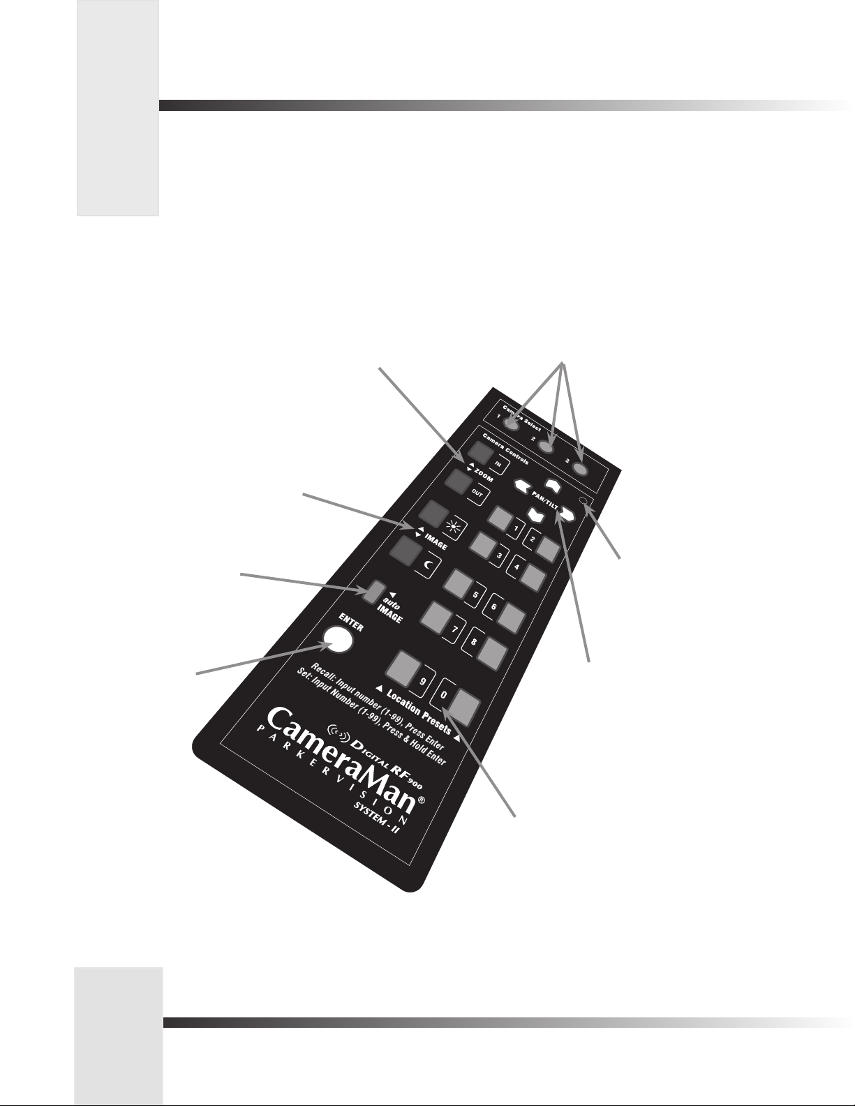
Buttons And Controls
Look at the front of the Camera Control Keypad. Here, you will find all the buttons
required to control the pan, tilt, zoom, and IMAGE, and also the buttons required
to store up to 99 location presets.
t Camera Select – Used
t Zoom In/Out Buttons – Used
to control the tightness of the
camera view.
t IMAGE Buttons (Brightness/Darkness) –
Used to brighten and darken the picture.
• Push the sun to brighten the image.
• Push the moon to darken the image.
to select between multiple
cameras (see page 6).
t autoIMAGE Button– Used
to enable camera to adjust
the brightness automatically
for each camera view.
t Enter – Used to
enter data or change
a camera location
preset.
t Indicator Light –
Used for visual
feedback of certain
keypad functions.
t Pan/Tilt Arrows – Used to
control the camera’s up/down,
and left/right movement.
t Location Preset Control Buttons (0–9)
– Used to store and recall up to 99
location presets.
Page 2
CameraMan
®
1-CCD Camera Control Keypad Operations Manual
Page 6
Connecting Your Keypad
Your Camera Control Keypad is designed to be used either in wireless or hard-wired mode. The wireless mode enables you to freely
move around the room. The hard-wired mode enables you to control the camera from greater distances. For either mode, use the
following steps to connect your keypad to your camera system:
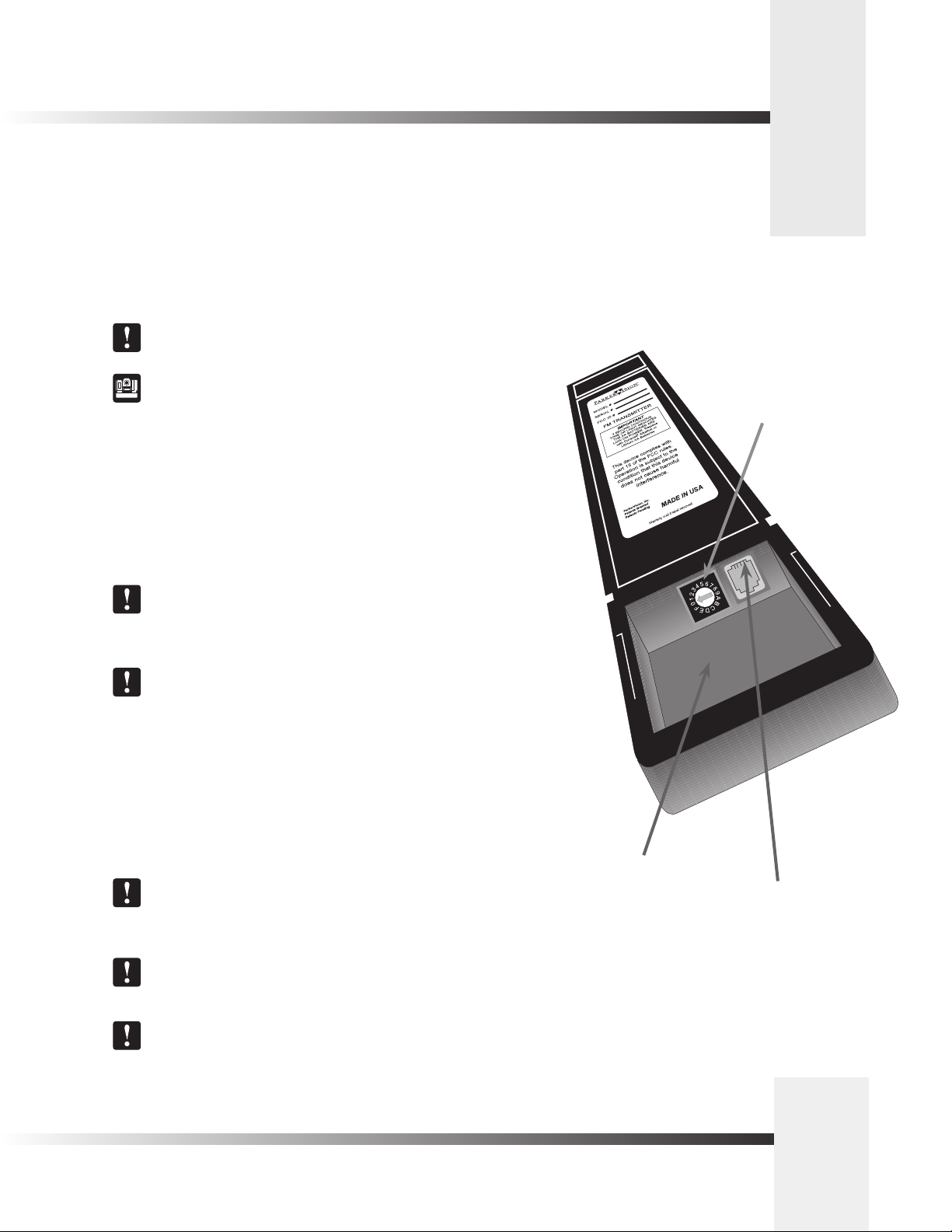
Step 1: Adjust the KEYPAD ADDRESS rotary switch (located in the battery compartment of
the keypad). The selected setting must be the same as the setting of the BASE UNIT
ADDRESS switch on the back of the Camera.
For multiple camera applications, refer to page 6.
For information on how to set the Base Unit Address on your CameraMan
camera, refer to the 1-CCD CameraMan Installation and Operations Manual .
Step 2: Congure the keypad for the desired mode:
For Wireless RF Mode (up to 60 feet/18.28 meters):
• Install the supplied AA batteries in the Camera Control Keypad by removing the
battery compartment door and inserting the batteries. You will hear a beep.
• Replace the battery compartment door.
• Press one of the PAN/TILT arrows on the keypad and verify that the LED on the front
of the keypad illuminates. This indicates that the batteries are installed properly.
Keypad Address
rotary switch
If the light does not illuminate, the batteries may be installed backwards. Reverse
the way the batteries are inserted, and try again. If a battery with a low charge
is installed, the keypad will emit a long beep.
If the batteries are inserted improperly, it will not damage the keypad,
it simply will not work.
For Hard-wired Mode (up to 250 feet/76.2 meters):
• Remove the batteries.
• Connect the CameraMan Keypad Cable supplied to the RJ-11 type
jack located in the battery compartment of the Keypad.
• Connect the other end of the cable to the PVI COM port on the CameraMan camera.
When the system is powered on, the light on the keypad should illuminate
momentarily, indicating the keypad is ready for operation. The light located
above the PVI COM port on the camera indicates communication activity.
You do not need to install batteries in the Camera Control Keypad when using
it in hard-wired mode.
Using a cable other than the one supplied for the PVI COM port
may cause damage.
Battery compartment
RJ-11 jack, for hardwired mode
Connect Your Camera Control Keypad
Page 3
Page 7

Orienting The Pan Arrows
You can configure your Camera Control Keypad to pan left and right according to your specific application. The following section
explains how to understand, configure, and control the camera’s panning motion.
Understanding The Panning Motion
Examples 1 and 2 depict instances when you might want to re-configure the pan arrows on
your Camera Control Keypad.
The default setting, shown in Example 1, is designed to operate while you are facing the
CameraMan camera. Some examples of applications that would benefit from the default
settings are:
• Distance Learning where you are the instructor.
• Presentations where you are the presenter and the audience members are watching
you on a monitor.
• Videoconferences where you are an on-screen participant.
• Any other application where you, the camera controller, need to be on-camera.
There are applications, however, in which you do not need to face the camera (example 2). In
these situations, the default setting would work. These applications require that you re-orient
the PAN arrows (see below). Some examples of applications that might benefit from this
re-orientation are:
• Presentations where you are not the presenter, but are controlling the camera’s
movement.
• Videoconferences where you are a moderator, but not an on-screen participant.
• Applications where you are controlling the camera from a control room.
• Any other application where you, the camera controller, do not need to be on-camera.
Example 1 (Default setting): Facing toward the
front of the camera
Your line of sight
Example 2: Facing away from the front of the camera
Re-Orienting The Pan Arrows
To re-orient (reverse) the setting of the pan arrows on your Camera Control Keypad:
1. Select the camera you wish to re-orient (see page 6, Multiple Camera Keypad Usage).
2. Press and hold the ENTER and autoIMAGE buttons simultaneously.
3. Listen for a beep, indicating that the reversal is complete.
4. Release the buttons simultaneously.
5. Verify that the orientation has changed.
Page 4
CameraMan
®
1-CCD Camera Control Keypad Operations Manual
Your line of sight
Page 8
Maximum Pan/Tilt Configuration
Now that you’ve learned how to program the pan arrows to meet your application’s needs, you can continue to customize how
your Camera Control Keypad works with your CameraMan system.
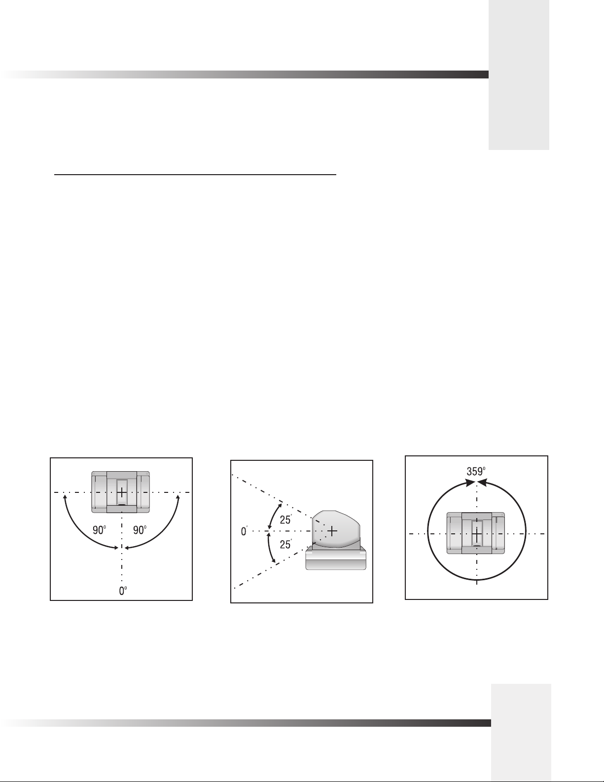
Maximum Pan/Tilt Travel
Once the CameraMan Camera is installed, you can configure the PAN/TILT settings to suit
your application. The CameraMan camera has a maximum pan range of 359°, but comes
programmed with factory default settings for maximum pan/tilt settings of ±90° of PAN and ±
25° of TILT. Use the following procedure to change the maximum position settings:
1. Select the camera you want to adjust (see page 6, Multiple Camera Keypad Usage).
2. Press and hold the ENTER button.
3. While holding the ENTER button, use the PAN/TILT arrows to move the camera to the
maximum desired position in one direction.
4. Release the ENTER button to set the maximum desired position for that direction.
5. Listen for two beeps, indicating that the maximum position for that direction
has been set.
6. If desired, repeat steps 2-5 until all maximum positions (left, right, up and down) are set.
7. If desired, repeat steps 1-6 for additional cameras.
180° Default Maximum Pan Settings 50° Default Maximum Tilt Settings 359° Maximum Pan Range
Page 5
Congure Your Camera Control Keypad
Page 9

Multiple Camera Applications
The Camera Control Keypad can control the pan, tilt, zoom, and IMAGE for up to three separate cameras. It is possible to
control multiple CameraMan cameras in one of three modes- wireless, hard-wired, or a combination of the two. Use the following
procedures to enable the keypad to work properly with multiple cameras:
Multiple Camera Control (wireless mode)
In this mode, the keypad communicates with each camera using RF (wireless) communications,
therefor the keypad is NOT hardwired.
1. Make sure your cameras are all within 60 feet/18.28 meters of the keypad.
2. Set the KEYPAD ADDRESS on your Camera Control Keypad to match the BASE UNIT
ADDRESS on the first camera.
See page 3 for more information on setting the KEYPAD ADDRESS.
3. Set the BASE UNIT ADDRESS on the second and third cameras to successively
follow the address that you used for the first camera.
Example:
Camera Base Unit Address Keypad Address
1 0 0
2 1
3 2
4. Set the RF Command configuration switch on all three cameras to ENABLE (up).
See your 1-CCD CameraMan Operations and Installation Manual for
more information on setting the configuration switches on your CameraMan
camera(s).
Multiple Camera Keypad Usage
To control any of the three cameras in your multi-camera network, press one of the CAMERA
SELECT buttons marked 1, 2 and 3 at the top of your keypad. Button 1 corresponds to Camera
One, button 2 corresponds to Camera Two, and button 3 corresponds to Camera Three.
Back of Camera Control Keypad
Camera 1
Camera 2
Camera 3
All camera control and Location Preset commands are issued to the last camera
selected.
Page 6
CameraMan
®
1-CCD Camera Control Keypad Operations Manual
Camera Select
buttons 1, 2 and 3
Page 10

UP
DOWN
SWITCH BANK
-A-
12 3 4 5 6 7 8
UP
DOWN
SWITCH BANK
-A-
SWITCH BANK
-B-
12 3 4 5 6 7 8
12 3 4 5 6 7 8
S-VIDEO
COMPOSITE
BASE UNIT
ADDRESS
TALLY LIGHT
INTERFACE
UP
DOWN
SWITCH BANK
-A-
SWITCH BANK
-B-
12 3 4 5 6 7 8
12 3 4 5 6 7 8
S-VIDEO
COMPOSITE
BASE UNIT
ADDRESS
TALLY LIGHT
INTERFACE
T-Connector
Camera 2
Camera 3
Camera 1
SWITCH BANK
-B-
12 3 4 5 6 7 8
S-VIDEO
COMPOSITE
BASE UNIT
ADDRESS
TALLY LIGHT
INTERFACE
BASE UNIT
ADDRESS
BASE UNIT
ADDRESS
BASE UNIT
ADDRESS
BASE UNIT
ADDRESS
0
1
2
3
4
5
6
7
8
9
A
B
C
D
E
F
Back of Camera Control Keypad
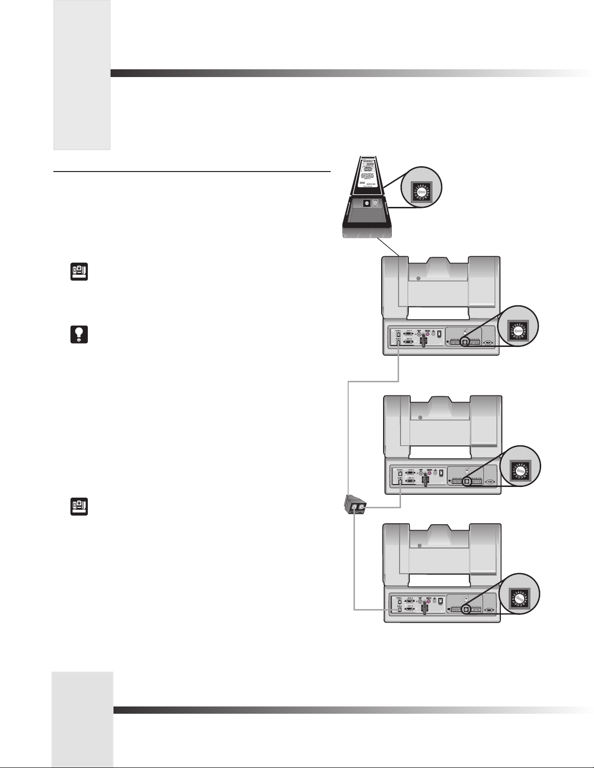
Multiple Camera Applications
Multiple Camera Control (hard-wired mode)
In this mode, the keypad communicates with camera one (1) using the hard-wired connection.
Any commands sent to cameras two or three will be received by camera one and sent to the
proper camera using RS-485 communications.
1. Make sure your cameras are daisy-chained together.
See your 1-CCD CameraMan Installation and Operations Manual for more
information on daisy-chaining your cameras together.
2.. Connect the Keypad to the PVI COM port on camera one (1) using the CameraMan
Keypad Cable (hard-wired mode only).
3. Set the KEYPAD ADDRESS on your Camera Control Keypad to match the BASE UNIT
ADDRESS on the first camera.
See page 3 for more information on setting the KEYPAD ADDRESS.
4. Set the BASE UNIT ADDRESS on the second and third cameras to successively
follow the address that you used for the first camera.
Example:
Camera Base Unit Address Keypad Address
1 0 0
2 1
3 2
5. Disable or enable the RF Command configuration switch on all cameras. THis setting
will not affect functionality.
See your 1-CCD CameraMan Installation and Operations Manual for
more information on setting the configuration switches on your CameraMan
camera(s).
Page 7
Congure Your Camera Control Keypad
Page 11
Multiple Camera Applications
UP
DOWN
SWITCH BANK
-A-
12 3 4 5 6 7 8
UP
DOWN
SWITCH BANK
-A-
SWITCH BANK
-B-
12 3 4 5 6 7 8
12 3 4 5 6 7 8
S-VIDEO
COMPOSITE
BASE UNIT
ADDRESS
TALLY LIGHT
INTERFACE
UP
DOWN
SWITCH BANK
-A-
SWITCH BANK
-B-
12 3 4 5 6 7 8
12 3 4 5 6 7 8
S-VIDEO
COMPOSITE
BASE UNIT
ADDRESS
TALLY LIGHT
INTERFACE
T-Connector
Camera 2
Camera 3
Camera 1
SWITCH BANK
-B-
12 3 4 5 6 7 8
S-VIDEO
COMPOSITE
BASE UNIT
ADDRESS
TALLY LIGHT
INTERFACE
BASE UNIT
ADDRESS
BASE UNIT
ADDRESS
BASE UNIT
ADDRESS
BASE UNIT
ADDRESS
0
1
2
3
4
5
6
7
8
9
A
B
C
D
E
F
Back of Camera Control Keypad
Multiple Camera Control (wireless and hard-wired combined mode)
In this mode, the keypad communicates with camera one (1) using RF (wireless). Any
commands sent to cameras two or three will be received by camera one and sent to the proper
camera using RS-485 communications. The keypad is NOT hardwired.
1. Make sure camera one is within 60 feet/18.28 meters of the keypad.
2. Make sure cameras two and three are daisy-chained to camera one.
See your 1-CCD CameraMan Installation and Operations Manual for more
information on daisy-chaining your cameras.
3. Set the KEYPAD ADDRESS on your Camera Control Keypad to match the BASE UNIT
ADDRESS on the first camera.
See page 3 for more information on setting the KEYPAD ADDRESS.
3. Set the BASE UNIT ADDRESS on the second and third cameras to successively
follow the address that you used for the first camera.
Example:
Camera Base Unit Address Keypad Address
1 0 0
2 1
3 2
5. Set the RF Command configuration switch on camera 1 to ENABLE (up). Set the RF
Command configuration switch on cameras 2 and 3 to DISABLE (down).
See your 1-CCD CameraMan Installation and Operations Manual for
more information on setting the configuration switches on your CameraMan
camera(s).
6. Set the Interlink configuration switch on Camera 1 to ON (up).
Page 8
CameraMan
®
1-CCD Camera Control Keypad Operations Manual
Page 12

Operating Your Camera Control Keypad
Now that you’ve learned what the buttons are for and have configured them to work properly, it’s time to put them to use.
Here is the basic functionality of each button:
Controlling The Image
Manual Pan/Tilt Arrows
Press the up, down, left, and right PAN/TILT arrows to pan or tilt the camera according
to your setup (see page 4).
Zoom Perspective Buttons
Press Zoom IN for the camera to zoom in for a tighter view.
Press Zoom OUT for the camera to zoom out for a wider view.
IMAGE Setting Buttons
By pressing either IMAGE button, the camera’s image control automatically becomes a manual
adjustment, overriding autoIMAGE.
Manual
• Press and release the top IMAGE button (sun) to open the iris.
• Press and release the bottom IMAGE button (moon) to close the iris.
The IMAGE setting can be adjusted manually and can be stored in a Location Preset.
You may want to use the manual IMAGE setting when you are not fully satisfied that
the video image is as dark or light as it should be. Otherwise, the IMAGE setting
automatically adjusts itself to the lighting conditions in all areas of the room.
autoIMAGE
In this mode, CameraMan automatically adjusts the IMAGE (light & dark) for each camera view.
Press autoIMAGE to enable automatic operation of the CameraMan’s IMAGE function.
An autoIMAGE setting can be stored in a Location Preset.
Use Your Camera Control Keypad
Page 9
Page 13

Operating Your Camera Control Keypad
To move quickly from view to view using the Camera Control Keypad, use the location preset function on the keypad. With location
presets, you can store and recall up to 99 pre-determined views by following these steps.
Working With Location Presets
What are Location Presets?
Location Presets are stored locations that can be recalled using the Camera Control
Keypad. Each Location Preset stores the following camera control settings:
• PAN/TILT position
• ZOOM perspective
• IMAGE setting
To Set or Change a Location Preset
1. Select the camera you want to program using the CAMERA SELECT buttons
(if you are using only one camera, press CAMERA SELECT 1).
2. Use PAN/TILT arrows to move the camera to the desired location.
3. If desired, use ZOOM In/Out to set the needed Zoom perspective.
4. If desired, use the manual IMAGE buttons to set the needed brightness.
5. Enter a Location Preset number (1–99).
6. Press and hold ENTER until you hear two beeps.
The two beeps indicate that the Location Preset has been stored.
Step 1
Step 2
Step 3
Step 4
To Recall a Location Preset
1. Select the camera (if only using one camera,
press CAMERA SELECT 1).
2. Enter the Location Preset number (1–99).
3. Press and release ENTER.
The CameraMan camera will move to the memorized location and recall the information
stored for that Location Preset.
Each CameraMan camera can store and recall up to 99 Location Presets.
Page 10
Step 5
Step 6
CameraMan
®
1-CCD Camera Control Keypad Operations Manual
Page 14

Operating Your Camera Control Keypad
You can use combinations of buttons to adjust the Shutter and Gain settings for each camera.
Adjusting Shutter Settings
1. Press Enter and ZOOM IN to adjust the Shutter UP.
2. Press Enter and ZOOM OUT to adjust the Shutter DOWN.
Adjusting Gain Settings
1. Press Enter and IMAGE lighten (sun) to increase the Gain.
2. Press Enter and IMAGE darken (moon) to decrease the Gain.
Use Your Camera Control Keypad
Page 11
Page 15
Setting Up Gen Lock with Your Control Keypad
You can adjust the Gen Lock settings to synchronize all video sources based on the sync pulses from one source, such as a remote
camera. When you switch between cameras, you may detect a flicker on your monitor. Adjusting the Gen Lock settings enable you
to remove the flicker for smooth transitions between cameras.
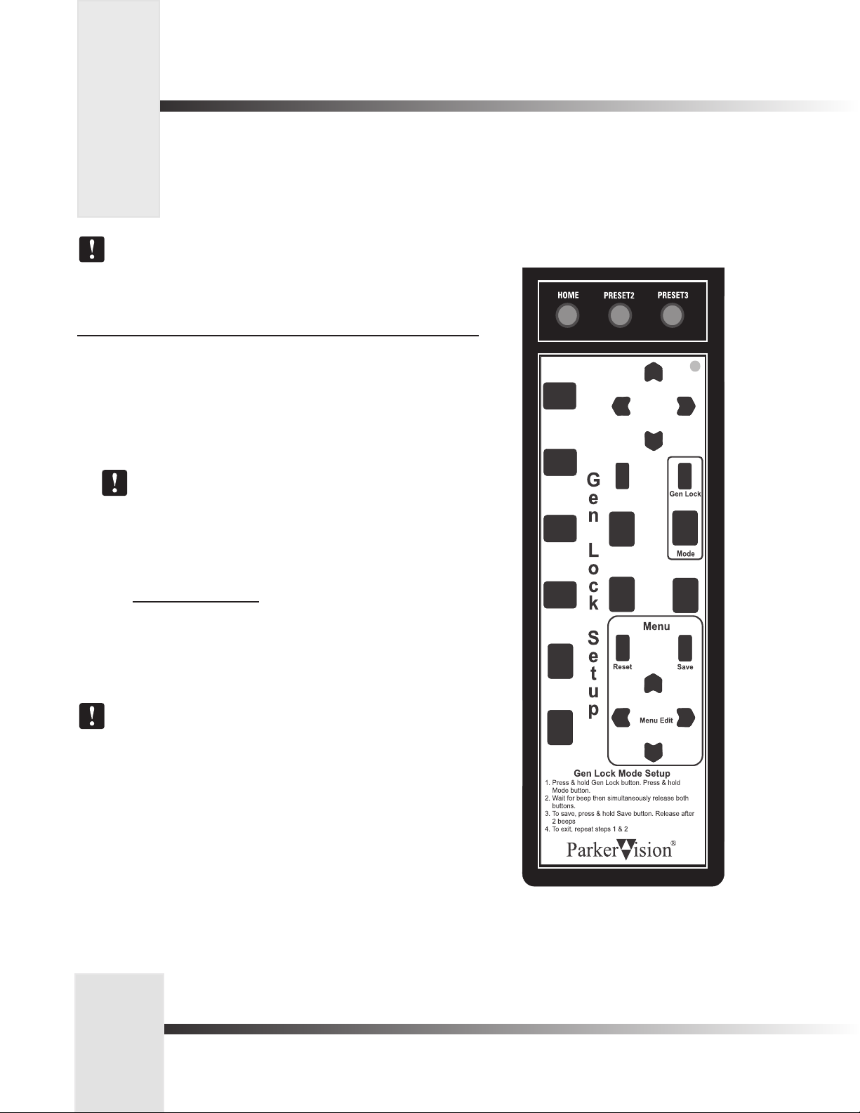
Place the Gen Lock Mode Setup card over the Keypad when adjusting Gen Lock. It
provides the instructions below and highlights the buttons you will use.
Gen Lock Setup (with the overlay card)
The following procedure will enable you to adjust Gen Lock settings with the Gen Lock Setup
overlay card.
1. Press and hold down the buttons labeled Gen Lock and Mode. After 2-3 seconds,
you will hear a beep.
2. Release the Gen Lock and Mode buttons. The Gen Lock Setup menu appears.
To reset the menu items to the default values, press the button labeled Reset.
3. Press the up and down Menu Edit arrows to move the arrow on-screen and to
select the item you want to change.
4. Press the left and right Menu Edit arrows to change the value for the following
items:
Menu Item
MODE AUTO or INT (internal)
H-PHASE -99° to +99°
SCFINE -99° to +-99°
5. To save your changes, press the button labeled Save.
The SC-PHASE is set using Dip Switch number 2: DOWN = 150° and UP = 180°.
6. Press and hold Gen Lock and MODE to exit.
Values
Page 12
CameraMan
®
1-CCD Camera Control Keypad Operations Manual
Page 16

Setting Up Gen Lock with Your Control Keypad
Gen Lock Setup (without the overlay card)
The following procedure will enable you to adjust Gen Lock settings without the Gen Lock
Setup overlay card.
1. Press and hold down button numbers 0 and 8. After 2-3 seconds, you will hear
a beep.
2. Release the 0 and 8 buttons. The Gen Lock Setup menu appears.
To reset the menu items to the default values, press button number 1.
3. Press the up and down PAN/TILT arrows to move the arrow on-screen and to select
the item you want to change.
4. Press the left and right PAN/TILT arrows to change the value for the following
items:
Menu Item
MODE AUTO or INT (internal)
H-PHASE -99° to +99°
SCFINE -99° to +99°
Values
5. To save your changes, press button number 2.
The SC-PHASE is set using Dip Switch number 2: DOWN = 150° and UP = 180°.
6. Press and hold 8 and 0 to exit.
Page 13
Meet Your Camera Control Keypad
Page 17

Appendix A : Troubleshooting and Specifications
If you have any problems with your Camera Control Keypad, please refer to the following Troubleshooting section. If you have
questions or problems after troubleshooting, please contact your authorized reseller, or contact Product
Support directly at 904-596-3500.
Troubleshooting
Problem: The Camera Control Keypad will not control the CameraMan
camera when used in the wireless RF mode.
Solution: 1. Verify that the batteries are installed in the keypad properly. (See
page 3).
2. Verify that the BASE UNIT ADDRESS switch on the back of the
CameraMan camera, and the BASE UNIT ADDRESS switch in the
battery compartment of the keypad are set to the same setting
(see page 3).
3. Verify that the RF command switch on the back of the
CameraMan Camera is set to ENABLE. (see your 1-CCD
CameraMan Installation and Operations Manual).
4. Verify that the light on the front of the Camera Control Keypad
illuminates for a few seconds when the batteries are first plugged
in.
5. Be sure that you have pressed the CAMERA SELECT button on
the Camera Control Keypad that corresponds to the camera you
want to control. (see page 6) If only using one camera be sure to
press CAMERA SELECT 1.
Problem: The Camera Control Keypad will not communicate with the
CameraMan Camera in the hard-wired mode.
Solution: 1. Verify that the CameraMan Keypad Cable is connected from the
PVI COM port on the back of the camera to the RJ-11 jack in the
battery compartment of the Camera Control Keypad (see page 3).
2. Verify that the BASE UNIT ADDRESS switch on the back of the
CameraMan camera, and the BASE UNIT ADDRESS switch in the
battery compartment of the keypad have the same setting
(see page 3).
3. Does the light on the front of the keypad come on for a few
seconds when the keypad is first plugged in? If not, replace
the cable with the supplied cable only.
4. Be sure that you have pressed the CAMERA SELECT button on
the Camera Control Keypad that corresponds to the camera you
want to control (see page 6). If only using one camera be sure
to press CAMERA SELECT 1.
Specifications
Wireless Mode:
RF Range: ........................... 60 ft./18.28 m from camera (typical)
Power:................................ (2) AA DURACELL® battery
Hard-Wired Mode:
Range:................................ 250 Ft./76.2mf from camera (typical)
Power:................................ supplied through cable
Keypad Dimensions: ........... US: 7.0"L x 2.20"W x 0.85"H
INTL: 17.78cm L x 5.59cm W x 2.16cm H
Return To Default
The return to default command resets the cameras
maximum pan/tilt position and pan/tilt orientation to their
factory settings, and clears Location Presets 1, 2, and 3
(presets 4-99 will not be reset). Please use with caution.
Returning to the Factory Defaults:
1. Press and hold the IMAGE (sun) button and button number
3 for approximately one second.
2. Release the buttons.
3. If off-center, the camera will return to the
default home position.
Page 14
CameraMan
®
1-CCD Camera Control Keypad Operations Manual
Page 18

Notes
Meet Your Camera Control Keypad
Page 15
Page 19

 Loading...