

Page 1

Operation Manual
MODEL 1200
DIGITAL PRODUCTION SWITCHER
software release
TP0716-01
FIRST PRINTNG: MARCH 1997
3.0
Page 2

Customer Service Information
Address
Mail: Shipping Only:
P.O. Box 1114 400 Providence Mine Rd
Grass Valley, CA 95945 Nevada City, CA 95959
Telephone
Tektronix, North America:
Tektronix, UK:
44-1628-403699
Tektronix, Hong Kong:
Tektronix. Brazil:
Tektronix. Mexico:
Elsewhere:
Fax:
(916) 478-3181
Distributor or sales office from whom equipment was purchased
55 11 3741-8417
52 5 666-6333
(800) 547-8949
852-2593-5500
Note that as of November 1, 1997 the FAX number changes to (530) 478-3181
E-Mail:
gvgservice@tek.com
Tektronix World Wide Web
http://www.tek.com
Copyright © Tektronix, Inc. All rights reserved. Printed in U.S.A.
Tektronix products are covered by U.S. and foreign patents, issued and pending. Information in this publication supersedes
that in all previously published material. Specifications and price change privileges reserved. TEKTRONIX, TEK, Grass Valley
Group, Borderline, E-MEM, TEN-X, Wavelink, and are registered trademarks, and Air Link, Auto Match, Doubletake, EDisk, Eagle V, Emphasys, EZ-Link, 409, Horizon, Grass Valley, Jogger, Kadenza, Kaleidoscope, K-Mask, Key-Layer, Key-Link,
Krystal, MASTER System, Master 21, MAX, Omni-Key, Performer, Programmed Motion, Silhouette, Softset, Streamline, Super
Edit, TEN-20, 20-TEN, Trace, TrailBlazer, VideoDesktop, Flex-Time, and XEDL are trademarks of Tektronix, Inc. P.O. Box 1000
Wilsonville, OR 97070-1000 U.S.A.
The information in this manual is furnished for informational use only, is subject to change without notice, and should not be
construed as a commitment by Tektronix, Inc. Tektronix assumes no responsibility or liability for any errors or inaccuracies that
may appear in this publication.
Tektronix, Inc., Video and Networking Division, P.O. Box 1114 Grass Valley, California 95945 U.S.A.
Page 3

Contents
Section 1 — Introduction
Introduction . . . . . . . . . . . . . . . . . . . . . . . . . . . . . . . . . . . . . . . . . . . . . . . . . . 1-1
Section Contents . . . . . . . . . . . . . . . . . . . . . . . . . . . . . . . . . . . . . . . . . . 1-1
Features of the Model 1200 . . . . . . . . . . . . . . . . . . . . . . . . . . . . . . . . . . . . . 1-2
Model 1200 Overview . . . . . . . . . . . . . . . . . . . . . . . . . . . . . . . . . . . . . . . . . 1-4
Section 2 — Startup
Introduction . . . . . . . . . . . . . . . . . . . . . . . . . . . . . . . . . . . . . . . . . . . . . . . . . . 2-1
System Startup or Restart . . . . . . . . . . . . . . . . . . . . . . . . . . . . . . . . . . . . . . 2-2
Startup . . . . . . . . . . . . . . . . . . . . . . . . . . . . . . . . . . . . . . . . . . . . . . . . . . . 2-2
Restart . . . . . . . . . . . . . . . . . . . . . . . . . . . . . . . . . . . . . . . . . . . . . . . . . . . 2-2
LampSaver Panel Sleep Mode . . . . . . . . . . . . . . . . . . . . . . . . . . . . . . . 2-2
Concepts You’ll Need to Know . . . . . . . . . . . . . . . . . . . . . . . . . . . . . . . . . 2-3
Delegation . . . . . . . . . . . . . . . . . . . . . . . . . . . . . . . . . . . . . . . . . . . . . . . . 2-3
Crosspoint Bus . . . . . . . . . . . . . . . . . . . . . . . . . . . . . . . . . . . . . . . . . . . . 2-3
Transition . . . . . . . . . . . . . . . . . . . . . . . . . . . . . . . . . . . . . . . . . . . . . . . . 2-4
Cut Transition . . . . . . . . . . . . . . . . . . . . . . . . . . . . . . . . . . . . . . . . . 2-4
Mix Transition . . . . . . . . . . . . . . . . . . . . . . . . . . . . . . . . . . . . . . . . 2-4
Wipe Transition . . . . . . . . . . . . . . . . . . . . . . . . . . . . . . . . . . . . . . . 2-5
Key . . . . . . . . . . . . . . . . . . . . . . . . . . . . . . . . . . . . . . . . . . . . . . . . . . . . . . 2-6
Luminance Key . . . . . . . . . . . . . . . . . . . . . . . . . . . . . . . . . . . . . . . . 2-6
Linear Key . . . . . . . . . . . . . . . . . . . . . . . . . . . . . . . . . . . . . . . . . . . . 2-7
Preset Pattern Key . . . . . . . . . . . . . . . . . . . . . . . . . . . . . . . . . . . . . 2-8
Chroma Key . . . . . . . . . . . . . . . . . . . . . . . . . . . . . . . . . . . . . . . . . . 2-8
Shaped Video . . . . . . . . . . . . . . . . . . . . . . . . . . . . . . . . . . . . . . . . . . . . 2-10
Effects Send . . . . . . . . . . . . . . . . . . . . . . . . . . . . . . . . . . . . . . . . . . . . . 2-10
Z-Key™ Depth . . . . . . . . . . . . . . . . . . . . . . . . . . . . . . . . . . . . . . . . . . . 2-11
E-MEM® Effects Memory . . . . . . . . . . . . . . . . . . . . . . . . . . . . . . . . . 2-11
v
Page 4

Contents
Section 3 — Controls & Menus
System Setup: Using the Configuration Menus . . . . . . . . . . . . . . . . . . . 2-12
Menu Pushbuttons and Knobs . . . . . . . . . . . . . . . . . . . . . . . . . . . . . . 2-12
Configuration Menu . . . . . . . . . . . . . . . . . . . . . . . . . . . . . . . . . . . . . . 2-13
System Parameters Menu . . . . . . . . . . . . . . . . . . . . . . . . . . . . . . . . . . 2-14
Define Inputs Menu . . . . . . . . . . . . . . . . . . . . . . . . . . . . . . . . . . . . . . . 2-16
Define Inputs . . . . . . . . . . . . . . . . . . . . . . . . . . . . . . . . . . . . . . . . . 2-16
Chroma Key Sources Menu . . . . . . . . . . . . . . . . . . . . . . . . . . . . . 2-18
Crosspoint Display Legends Menu . . . . . . . . . . . . . . . . . . . . . . 2-19
Crosspoint Map Menu . . . . . . . . . . . . . . . . . . . . . . . . . . . . . . . . . . . . 2-20
Outputs Menu . . . . . . . . . . . . . . . . . . . . . . . . . . . . . . . . . . . . . . . . . . . 2-22
Timing Menu . . . . . . . . . . . . . . . . . . . . . . . . . . . . . . . . . . . . . . . . . . . . 2-23
Port Menu . . . . . . . . . . . . . . . . . . . . . . . . . . . . . . . . . . . . . . . . . . . . . . . 2-24
GPI Menus . . . . . . . . . . . . . . . . . . . . . . . . . . . . . . . . . . . . . . . . . . . . . . 2-26
Tally Menu . . . . . . . . . . . . . . . . . . . . . . . . . . . . . . . . . . . . . . . . . . . . . . 2-28
Introduction . . . . . . . . . . . . . . . . . . . . . . . . . . . . . . . . . . . . . . . . . . . . . . . . . . 3-1
Bus Delegates . . . . . . . . . . . . . . . . . . . . . . . . . . . . . . . . . . . . . . . . . . . . . . . . . 3-4
Crosspoint Buses . . . . . . . . . . . . . . . . . . . . . . . . . . . . . . . . . . . . . . . . . . . . . . 3-5
PST (Preset) Bus . . . . . . . . . . . . . . . . . . . . . . . . . . . . . . . . . . . . . . . . . . . 3-6
PGM (Program) Bus . . . . . . . . . . . . . . . . . . . . . . . . . . . . . . . . . . . . . . . 3-6
Key Bus . . . . . . . . . . . . . . . . . . . . . . . . . . . . . . . . . . . . . . . . . . . . . . . . . . 3-7
Aux Bus 1 and Aux Bus 2 . . . . . . . . . . . . . . . . . . . . . . . . . . . . . . . . . . . 3-8
Satellite Aux Bus Panels . . . . . . . . . . . . . . . . . . . . . . . . . . . . . . . . . . . . 3-8
Downstream Keyer (DSK) . . . . . . . . . . . . . . . . . . . . . . . . . . . . . . . . . . . . . . 3-9
DSK Preview . . . . . . . . . . . . . . . . . . . . . . . . . . . . . . . . . . . . . . . . . . . . . 3-10
DSK Cut . . . . . . . . . . . . . . . . . . . . . . . . . . . . . . . . . . . . . . . . . . . . . . . . . 3-10
DSK Mix . . . . . . . . . . . . . . . . . . . . . . . . . . . . . . . . . . . . . . . . . . . . . . . . 3-10
Effects Send . . . . . . . . . . . . . . . . . . . . . . . . . . . . . . . . . . . . . . . . . . . . . . . . . 3-11
E-MEM Effects Memory . . . . . . . . . . . . . . . . . . . . . . . . . . . . . . . . . . . . . . . 3-12
Learn Button . . . . . . . . . . . . . . . . . . . . . . . . . . . . . . . . . . . . . . . . . . . . . 3-12
Register Buttons . . . . . . . . . . . . . . . . . . . . . . . . . . . . . . . . . . . . . . . . . . 3-13
Undo/Decimal Point . . . . . . . . . . . . . . . . . . . . . . . . . . . . . . . . . . . . . . 3-13
Trans Buttons . . . . . . . . . . . . . . . . . . . . . . . . . . . . . . . . . . . . . . . . . . . . 3-14
Clear . . . . . . . . . . . . . . . . . . . . . . . . . . . . . . . . . . . . . . . . . . . . . . . . . . . . 3-14
vi
Page 5

Contents
External Interface . . . . . . . . . . . . . . . . . . . . . . . . . . . . . . . . . . . . . . . . . . . . 3-15
Editor Enable . . . . . . . . . . . . . . . . . . . . . . . . . . . . . . . . . . . . . . . . . . . . 3-15
GPI Enable . . . . . . . . . . . . . . . . . . . . . . . . . . . . . . . . . . . . . . . . . . . . . . 3-15
DPM Enable . . . . . . . . . . . . . . . . . . . . . . . . . . . . . . . . . . . . . . . . . . . . . 3-15
Fade To Black . . . . . . . . . . . . . . . . . . . . . . . . . . . . . . . . . . . . . . . . . . . . . . . 3-16
Black Cut . . . . . . . . . . . . . . . . . . . . . . . . . . . . . . . . . . . . . . . . . . . . . . . . 3-16
Black Mix . . . . . . . . . . . . . . . . . . . . . . . . . . . . . . . . . . . . . . . . . . . . . . . 3-16
Keyer . . . . . . . . . . . . . . . . . . . . . . . . . . . . . . . . . . . . . . . . . . . . . . . . . . . . . . . 3-17
Keyer Delegation Pushbuttons . . . . . . . . . . . . . . . . . . . . . . . . . . . . . 3-17
Key Source Type: Video Key and Auto Select Key . . . . . . . . . . . . 3-18
Split Key . . . . . . . . . . . . . . . . . . . . . . . . . . . . . . . . . . . . . . . . . . . . . 3-18
Key Fill: Video or Matte . . . . . . . . . . . . . . . . . . . . . . . . . . . . . . . . . . . 3-19
Key Type: Linear Key, Luma Key, Chroma Key, Preset Pattern . 3-19
Linear Key . . . . . . . . . . . . . . . . . . . . . . . . . . . . . . . . . . . . . . . . . . . 3-19
Luma Key . . . . . . . . . . . . . . . . . . . . . . . . . . . . . . . . . . . . . . . . . . . 3-20
Chroma Key and Auto Setup . . . . . . . . . . . . . . . . . . . . . . . . . . . 3-20
Preset Pattern . . . . . . . . . . . . . . . . . . . . . . . . . . . . . . . . . . . . . . . . 3-21
Key Modifiers and Adjustments . . . . . . . . . . . . . . . . . . . . . . . . . . . . 3-21
Key Over . . . . . . . . . . . . . . . . . . . . . . . . . . . . . . . . . . . . . . . . . . . . 3-21
Invert . . . . . . . . . . . . . . . . . . . . . . . . . . . . . . . . . . . . . . . . . . . . . . . 3-21
Mask . . . . . . . . . . . . . . . . . . . . . . . . . . . . . . . . . . . . . . . . . . . . . . . . 3-22
Force Mask . . . . . . . . . . . . . . . . . . . . . . . . . . . . . . . . . . . . . . . . . . 3-22
Show Key . . . . . . . . . . . . . . . . . . . . . . . . . . . . . . . . . . . . . . . . . . . . 3-22
Key Opacity . . . . . . . . . . . . . . . . . . . . . . . . . . . . . . . . . . . . . . . . . . 3-22
Gain and Clip . . . . . . . . . . . . . . . . . . . . . . . . . . . . . . . . . . . . . . . . 3-23
Borderline . . . . . . . . . . . . . . . . . . . . . . . . . . . . . . . . . . . . . . . . . . . . . . . 3-24
Normal . . . . . . . . . . . . . . . . . . . . . . . . . . . . . . . . . . . . . . . . . . . . . . 3-24
Border . . . . . . . . . . . . . . . . . . . . . . . . . . . . . . . . . . . . . . . . . . . . . . . 3-24
Shadow . . . . . . . . . . . . . . . . . . . . . . . . . . . . . . . . . . . . . . . . . . . . . 3-24
Extrude . . . . . . . . . . . . . . . . . . . . . . . . . . . . . . . . . . . . . . . . . . . . . . 3-24
Outline . . . . . . . . . . . . . . . . . . . . . . . . . . . . . . . . . . . . . . . . . . . . . . 3-25
Key Memory and Key Copy Features . . . . . . . . . . . . . . . . . . . . . . . 3-25
Matte . . . . . . . . . . . . . . . . . . . . . . . . . . . . . . . . . . . . . . . . . . . . . . . . . . . . . . . 3-26
Matte Controls . . . . . . . . . . . . . . . . . . . . . . . . . . . . . . . . . . . . . . . 3-26
Matte Delegation . . . . . . . . . . . . . . . . . . . . . . . . . . . . . . . . . . . . . 3-26
vii
Page 6

Contents
Pattern . . . . . . . . . . . . . . . . . . . . . . . . . . . . . . . . . . . . . . . . . . . . . . . . . . . . . . 3-28
Pattern Selection Buttons . . . . . . . . . . . . . . . . . . . . . . . . . . . . . . . . . . 3-29
User Wipe Buttons . . . . . . . . . . . . . . . . . . . . . . . . . . . . . . . . . . . . . . . . 3-29
Pattern Adjustments . . . . . . . . . . . . . . . . . . . . . . . . . . . . . . . . . . . . . . 3-30
Positioner (Joystick) . . . . . . . . . . . . . . . . . . . . . . . . . . . . . . . . . . . 3-30
Wipe Direction . . . . . . . . . . . . . . . . . . . . . . . . . . . . . . . . . . . . . . . 3-30
Mask Preset Pattern/Wipe . . . . . . . . . . . . . . . . . . . . . . . . . . . . . 3-30
Size and Border Width, Softness, and Symmetry . . . . . . . . . . 3-31
Mask/Preset Invert . . . . . . . . . . . . . . . . . . . . . . . . . . . . . . . . . . . 3-31
Wipe Menu . . . . . . . . . . . . . . . . . . . . . . . . . . . . . . . . . . . . . . . . . . 3-31
Transition . . . . . . . . . . . . . . . . . . . . . . . . . . . . . . . . . . . . . . . . . . . . . . . . . . . 3-32
Bkgd, Key 1, Key 2 . . . . . . . . . . . . . . . . . . . . . . . . . . . . . . . . . . . . . . . . 3-33
Bkgd . . . . . . . . . . . . . . . . . . . . . . . . . . . . . . . . . . . . . . . . . . . . . . . . 3-33
Key 1 and Key 2 . . . . . . . . . . . . . . . . . . . . . . . . . . . . . . . . . . . . . . 3-33
Mix and Wipe Transition Type . . . . . . . . . . . . . . . . . . . . . . . . . . . . . 3-34
Mix . . . . . . . . . . . . . . . . . . . . . . . . . . . . . . . . . . . . . . . . . . . . . . . . . 3-34
Wipe . . . . . . . . . . . . . . . . . . . . . . . . . . . . . . . . . . . . . . . . . . . . . . . . 3-34
Transition Controls: Cut, Auto Trans, and Lever Arm . . . . . . . . . 3-35
Visual Display and Menus . . . . . . . . . . . . . . . . . . . . . . . . . . . . . . . . . . . . . 3-36
Menu Pushbuttons and Knobs . . . . . . . . . . . . . . . . . . . . . . . . . . . . . . 3-37
Keypad Numeric Entry . . . . . . . . . . . . . . . . . . . . . . . . . . . . . . . . . . . . 3-37
Double-Press Pushbuttons . . . . . . . . . . . . . . . . . . . . . . . . . . . . . . . . . 3-38
Menus . . . . . . . . . . . . . . . . . . . . . . . . . . . . . . . . . . . . . . . . . . . . . . . . . . 3-39
Menu Tree . . . . . . . . . . . . . . . . . . . . . . . . . . . . . . . . . . . . . . . . . . . . . . . 3-40
Chroma Key Menus . . . . . . . . . . . . . . . . . . . . . . . . . . . . . . . . . . . . . . . . . . 3-42
Chroma Key Menu Functions: . . . . . . . . . . . . . . . . . . . . . . . . . . 3-42
Chroma Key Auto Setup Menu . . . . . . . . . . . . . . . . . . . . . . . . . . . . . 3-44
Auto Setup Menu Functions: . . . . . . . . . . . . . . . . . . . . . . . . . . . 3-44
Chroma Key Fgd Suppress Menu . . . . . . . . . . . . . . . . . . . . . . . . . . . 3-46
Foreground Suppress Menu Functions: . . . . . . . . . . . . . . . . . . 3-46
Chroma Key Edge Menu . . . . . . . . . . . . . . . . . . . . . . . . . . . . . . . . . . 3-48
Chroma Key Edge Menu Functions: . . . . . . . . . . . . . . . . . . . . . 3-48
Chroma Key Shadow Proc Menu . . . . . . . . . . . . . . . . . . . . . . . . . . . 3-50
Shadow Proc Menu Functions: . . . . . . . . . . . . . . . . . . . . . . . . . . 3-50
Chroma Key Force Mask Menu . . . . . . . . . . . . . . . . . . . . . . . . . . . . . 3-52
Force Mask Menu Functions: . . . . . . . . . . . . . . . . . . . . . . . . . . . 3-52
viii
Page 7

Contents
Configuration Menus . . . . . . . . . . . . . . . . . . . . . . . . . . . . . . . . . . . . . . . . . 3-54
Configuration Menu Functions: . . . . . . . . . . . . . . . . . . . . . . . . . 3-54
System Parameters Menu . . . . . . . . . . . . . . . . . . . . . . . . . . . . . . . . . . 3-56
System Parameters Menu Functions: . . . . . . . . . . . . . . . . . . . . 3-56
Define Inputs Menu . . . . . . . . . . . . . . . . . . . . . . . . . . . . . . . . . . . . . . 3-58
Define Inputs Menu Functions: . . . . . . . . . . . . . . . . . . . . . . . . . 3-58
Configuration Name Inputs Menus . . . . . . . . . . . . . . . . . . . . . 3-60
4:4:4 Chroma Key Sources Menu . . . . . . . . . . . . . . . . . . . . . . . . 3-62
Crosspoint Display Legends Menu . . . . . . . . . . . . . . . . . . . . . . 3-64
Crosspoint Display Legends Menu Functions: . . . . . . . . . . . . 3-64
Crosspoint Map Menu . . . . . . . . . . . . . . . . . . . . . . . . . . . . . . . . . . . . 3-66
Crosspoint Map Menu Functions: . . . . . . . . . . . . . . . . . . . . . . . 3-66
Outputs Menu . . . . . . . . . . . . . . . . . . . . . . . . . . . . . . . . . . . . . . . . . . . 3-68
Outputs Menu Functions: . . . . . . . . . . . . . . . . . . . . . . . . . . . . . . 3-68
Timing Menu . . . . . . . . . . . . . . . . . . . . . . . . . . . . . . . . . . . . . . . . . . . . 3-70
Port Configuration Menu . . . . . . . . . . . . . . . . . . . . . . . . . . . . . . . . . . 3-72
Port Configuration Menu Functions: . . . . . . . . . . . . . . . . . . . . 3-72
GPI Menus . . . . . . . . . . . . . . . . . . . . . . . . . . . . . . . . . . . . . . . . . . . . . . 3-74
GPI Input and Output Menu Functions: . . . . . . . . . . . . . . . . . . 3-74
Tally Menu . . . . . . . . . . . . . . . . . . . . . . . . . . . . . . . . . . . . . . . . . . . . . . 3-76
Tally Menu Functions: . . . . . . . . . . . . . . . . . . . . . . . . . . . . . . . . . 3-76
Copy/Swap Menus . . . . . . . . . . . . . . . . . . . . . . . . . . . . . . . . . . . . . . . . . . 3-77
Disk Menus . . . . . . . . . . . . . . . . . . . . . . . . . . . . . . . . . . . . . . . . . . . . . . . . . 3-82
Disk Menu Functions: . . . . . . . . . . . . . . . . . . . . . . . . . . . . . . . . . 3-82
Disk Save Menu . . . . . . . . . . . . . . . . . . . . . . . . . . . . . . . . . . . . . . . . . . 3-84
Disk Save Menu Functions: . . . . . . . . . . . . . . . . . . . . . . . . . . . . 3-84
Save Switcher Configuration to Disk . . . . . . . . . . . . . . . . . . . . 3-86
Name File . . . . . . . . . . . . . . . . . . . . . . . . . . . . . . . . . . . . . . . . . . . . 3-88
Disk Load Menu . . . . . . . . . . . . . . . . . . . . . . . . . . . . . . . . . . . . . . . . . 3-90
Disk Load Menu Functions: . . . . . . . . . . . . . . . . . . . . . . . . . . . . 3-90
Load Configuration and Load All . . . . . . . . . . . . . . . . . . . . . . . 3-91
Disk Util Menu . . . . . . . . . . . . . . . . . . . . . . . . . . . . . . . . . . . . . . . . . . . 3-92
Disk Load Menu Functions: . . . . . . . . . . . . . . . . . . . . . . . . . . . . 3-92
Moving Files to Other Directories . . . . . . . . . . . . . . . . . . . . . . . 3-93
Name Directory . . . . . . . . . . . . . . . . . . . . . . . . . . . . . . . . . . . . . . 3-94
Disk Format Menu . . . . . . . . . . . . . . . . . . . . . . . . . . . . . . . . . . . . . . . . 3-96
Disk Format Menu Functions: . . . . . . . . . . . . . . . . . . . . . . . . . . 3-96
Name Volume . . . . . . . . . . . . . . . . . . . . . . . . . . . . . . . . . . . . . . . . 3-98
ix
Page 8

Contents
Keyer Menu . . . . . . . . . . . . . . . . . . . . . . . . . . . . . . . . . . . . . . . . . . . . . . . . 3-100
Keyer Menu Functions: . . . . . . . . . . . . . . . . . . . . . . . . . . . . . . . 3-100
Key Border . . . . . . . . . . . . . . . . . . . . . . . . . . . . . . . . . . . . . . . . . . 3-102
Last Menu . . . . . . . . . . . . . . . . . . . . . . . . . . . . . . . . . . . . . . . . . . . . . . . . . . 3-104
Misc Menu . . . . . . . . . . . . . . . . . . . . . . . . . . . . . . . . . . . . . . . . . . . . . . . . . 3-104
Priority/Depth Menu . . . . . . . . . . . . . . . . . . . . . . . . . . . . . . . . . . . . . . . . 3-106
Priority/Depth Menu Functions: . . . . . . . . . . . . . . . . . . . . . . . 3-106
Proc Amp Menus . . . . . . . . . . . . . . . . . . . . . . . . . . . . . . . . . . . . . . . . . . . 3-108
Proc Amp Menu Functions: . . . . . . . . . . . . . . . . . . . . . . . . . . . 3-108
Status Menus . . . . . . . . . . . . . . . . . . . . . . . . . . . . . . . . . . . . . . . . . . . . . . . 3-110
Wipe Menus . . . . . . . . . . . . . . . . . . . . . . . . . . . . . . . . . . . . . . . . . . . . . . . . 3-112
Wipe Menu Functions: . . . . . . . . . . . . . . . . . . . . . . . . . . . . . . . . 3-112
Wipe Multiply Menu . . . . . . . . . . . . . . . . . . . . . . . . . . . . . . . . . . . . . 3-114
Wipe Multiply Menu Functions: . . . . . . . . . . . . . . . . . . . . . . . 3-114
Wipe Modulation Menu . . . . . . . . . . . . . . . . . . . . . . . . . . . . . . . . . . 3-116
Wipe Modulation Menu Functions: . . . . . . . . . . . . . . . . . . . . . 3-116
Readout Display Option . . . . . . . . . . . . . . . . . . . . . . . . . . . . . . . . . . . . . 3-118
Section 4 — Basic Operations
Introduction . . . . . . . . . . . . . . . . . . . . . . . . . . . . . . . . . . . . . . . . . . . . . . . . . . 4-1
Starting Conditions . . . . . . . . . . . . . . . . . . . . . . . . . . . . . . . . . . . . . . . . . . . . 4-1
Transitions . . . . . . . . . . . . . . . . . . . . . . . . . . . . . . . . . . . . . . . . . . . . . . . . . . . 4-2
Background Cut . . . . . . . . . . . . . . . . . . . . . . . . . . . . . . . . . . . . . . . . . . . 4-2
Background Mix . . . . . . . . . . . . . . . . . . . . . . . . . . . . . . . . . . . . . . . . . . . 4-3
Background Wipe . . . . . . . . . . . . . . . . . . . . . . . . . . . . . . . . . . . . . . . . . 4-4
Learning User Wipes . . . . . . . . . . . . . . . . . . . . . . . . . . . . . . . . . . . 4-5
Fade to Black . . . . . . . . . . . . . . . . . . . . . . . . . . . . . . . . . . . . . . . . . . . . . . 4-6
Setting Transition Rates . . . . . . . . . . . . . . . . . . . . . . . . . . . . . . . . . . . . 4-6
Matte Effects . . . . . . . . . . . . . . . . . . . . . . . . . . . . . . . . . . . . . . . . . . . . . . . . . 4-7
Luminance and Linear Keying . . . . . . . . . . . . . . . . . . . . . . . . . . . . . . . . . . 4-8
Key Transition . . . . . . . . . . . . . . . . . . . . . . . . . . . . . . . . . . . . . . . . . . . 4-10
Preset Pattern Keying . . . . . . . . . . . . . . . . . . . . . . . . . . . . . . . . . . . . . . . . . 4-12
Chroma Keying . . . . . . . . . . . . . . . . . . . . . . . . . . . . . . . . . . . . . . . . . . . . . . 4-14
Using E-MEM Effects Memory . . . . . . . . . . . . . . . . . . . . . . . . . . . . . . . . . 4-16
x
Page 9

Section 5 — Advanced Operations
Introduction . . . . . . . . . . . . . . . . . . . . . . . . . . . . . . . . . . . . . . . . . . . . . . . . . . 5-1
Starting Conditions . . . . . . . . . . . . . . . . . . . . . . . . . . . . . . . . . . . . . . . . . . . . 5-1
Proc Amp Controls . . . . . . . . . . . . . . . . . . . . . . . . . . . . . . . . . . . . . . . . . . . . 5-2
Monochrome Video Effect . . . . . . . . . . . . . . . . . . . . . . . . . . . . . . . . . . 5-3
Matte Wash . . . . . . . . . . . . . . . . . . . . . . . . . . . . . . . . . . . . . . . . . . . . . . . . . . 5-4
Matte Wash Method 1 . . . . . . . . . . . . . . . . . . . . . . . . . . . . . . . . . . . . . . 5-4
Matte Wash Method 2 . . . . . . . . . . . . . . . . . . . . . . . . . . . . . . . . . . . . . . 5-5
Spotlight . . . . . . . . . . . . . . . . . . . . . . . . . . . . . . . . . . . . . . . . . . . . . . . . . . . . . 5-6
Spotlight Method 1 . . . . . . . . . . . . . . . . . . . . . . . . . . . . . . . . . . . . . . . . 5-6
Spotlight Method 2 . . . . . . . . . . . . . . . . . . . . . . . . . . . . . . . . . . . . . . . . 5-7
Advanced Chroma Keying . . . . . . . . . . . . . . . . . . . . . . . . . . . . . . . . . . . . . 5-8
Using Effects Send to Fly a Key . . . . . . . . . . . . . . . . . . . . . . . . . . . . . . . . 5-10
Using Aux Buses to Fly a Key . . . . . . . . . . . . . . . . . . . . . . . . . . . . . . . . . . 5-11
Contents
xi
Page 10

Contents
List of Illustrations
Figure 1-1 Model 1200 Simplified Functional Block Diagram . . . . . . . . . . 1-4
Figure 2-1 A Mix Transition . . . . . . . . . . . . . . . . . . . . . . . . . . . . . . . . . . . . . . . 2-4
Figure 2-2 A Wipe Transition . . . . . . . . . . . . . . . . . . . . . . . . . . . . . . . . . . . . . 2-5
Figure 2-3 Luminance Key Example . . . . . . . . . . . . . . . . . . . . . . . . . . . . . . . . 2-7
Figure 2-4 Chroma Key Example . . . . . . . . . . . . . . . . . . . . . . . . . . . . . . . . . . 2-9
Figure 2-5 1200 Configuration Menu Tree . . . . . . . . . . . . . . . . . . . . . . . . . . 2-12
Figure 2-6 Configuration Menu . . . . . . . . . . . . . . . . . . . . . . . . . . . . . . . . . . . 2-13
Figure 2-7 System Parameters Menu . . . . . . . . . . . . . . . . . . . . . . . . . . . . . . 2-15
Figure 2-8 Define Inputs Menu . . . . . . . . . . . . . . . . . . . . . . . . . . . . . . . . . . . 2-17
Figure 2-9 4:4:4 Chroma Key Sources Menu . . . . . . . . . . . . . . . . . . . . . . . . 2-18
Figure 2-10 Crosspoint Display Legends Menu . . . . . . . . . . . . . . . . . . . . . . 2-19
Figure 2-11 Crosspoint Map Menu . . . . . . . . . . . . . . . . . . . . . . . . . . . . . . . . . 2-21
Figure 2-12 Outputs Menu . . . . . . . . . . . . . . . . . . . . . . . . . . . . . . . . . . . . . . . . 2-22
Figure 2-13 Timing Menu . . . . . . . . . . . . . . . . . . . . . . . . . . . . . . . . . . . . . . . . . 2-23
Figure 2-14 Port Configuration Menu . . . . . . . . . . . . . . . . . . . . . . . . . . . . . . 2-25
Figure 2-15 GPI Inputs Menu . . . . . . . . . . . . . . . . . . . . . . . . . . . . . . . . . . . . . 2-27
Figure 2-16 GPI Outputs Menu . . . . . . . . . . . . . . . . . . . . . . . . . . . . . . . . . . . . 2-27
Figure 2-17 Tally Menu . . . . . . . . . . . . . . . . . . . . . . . . . . . . . . . . . . . . . . . . . . . 2-28
xii
Figure 3-1 Model 1200 Control Panel . . . . . . . . . . . . . . . . . . . . . . . . . . . . . . . 3-2
Figure 3-2 Bus Delegates Panel . . . . . . . . . . . . . . . . . . . . . . . . . . . . . . . . . . . . 3-4
Figure 3-3 Crosspoint Buses . . . . . . . . . . . . . . . . . . . . . . . . . . . . . . . . . . . . . . . 3-6
Figure 3-4 Downstream Keyer (DSK) Panel Section . . . . . . . . . . . . . . . . . . 3-9
Figure 3-5 Effects Send Panel Section . . . . . . . . . . . . . . . . . . . . . . . . . . . . . . 3-11
Figure 3-6 E-MEM Panel Section . . . . . . . . . . . . . . . . . . . . . . . . . . . . . . . . . . 3-12
Figure 3-7 External Interface Panel Section . . . . . . . . . . . . . . . . . . . . . . . . . 3-15
Figure 3-8 Fade To Black Panel . . . . . . . . . . . . . . . . . . . . . . . . . . . . . . . . . . . 3-16
Figure 3-9 Keyer Panel . . . . . . . . . . . . . . . . . . . . . . . . . . . . . . . . . . . . . . . . . . 3-17
Figure 3-10 Foreground Clip/Background Clip Operation . . . . . . . . . . . . 3-23
Figure 3-11 Borderline Modes . . . . . . . . . . . . . . . . . . . . . . . . . . . . . . . . . . . . . 3-25
Figure 3-12 Matte Panel Section . . . . . . . . . . . . . . . . . . . . . . . . . . . . . . . . . . . 3-27
Figure 3-13 Pattern Panel Section . . . . . . . . . . . . . . . . . . . . . . . . . . . . . . . . . . 3-28
Figure 3-14 Transition Controls . . . . . . . . . . . . . . . . . . . . . . . . . . . . . . . . . . . . 3-32
Figure 3-15 Visual Display Panel Section . . . . . . . . . . . . . . . . . . . . . . . . . . . . 3-36
Figure 3-16 Display Menu Tree . . . . . . . . . . . . . . . . . . . . . . . . . . . . . . . . . . . . 3-40
Figure 3-17 Chroma Key Top Menu . . . . . . . . . . . . . . . . . . . . . . . . . . . . . . . . 3-43
Figure 3-18 Chroma Key Auto Setup Menu . . . . . . . . . . . . . . . . . . . . . . . . . 3-45
Page 11

Contents
List of Illustrations – continued
Figure 3-19 Chroma Key Foreground Suppress Menu . . . . . . . . . . . . . . . . 3-47
Figure 3-20 Chroma Key Edge Menu . . . . . . . . . . . . . . . . . . . . . . . . . . . . . . . 3-49
Figure 3-21 Chroma Key Shadow Proc Menu . . . . . . . . . . . . . . . . . . . . . . . 3-51
Figure 3-22 Chroma Key Force Mask Menu . . . . . . . . . . . . . . . . . . . . . . . . . 3-53
Figure 3-23 Configuration Top Menu . . . . . . . . . . . . . . . . . . . . . . . . . . . . . . 3-55
Figure 3-24 System Parameters Menu . . . . . . . . . . . . . . . . . . . . . . . . . . . . . . 3-57
Figure 3-25 Define Inputs Menu . . . . . . . . . . . . . . . . . . . . . . . . . . . . . . . . . . . 3-59
Figure 3-26 Signal Name Menu . . . . . . . . . . . . . . . . . . . . . . . . . . . . . . . . . . . . 3-61
Figure 3-27 Local Name Menu . . . . . . . . . . . . . . . . . . . . . . . . . . . . . . . . . . . . 3-61
Figure 3-28 4:4:4 Chroma Key Sources Menu . . . . . . . . . . . . . . . . . . . . . . . . 3-63
Figure 3-29 Crosspoint Display Legends Menu . . . . . . . . . . . . . . . . . . . . . . 3-65
Figure 3-30 Crosspoint Map Menu . . . . . . . . . . . . . . . . . . . . . . . . . . . . . . . . . 3-67
Figure 3-31 Outputs Menu . . . . . . . . . . . . . . . . . . . . . . . . . . . . . . . . . . . . . . . . 3-69
Figure 3-32 Timing Menu . . . . . . . . . . . . . . . . . . . . . . . . . . . . . . . . . . . . . . . . 3-71
Figure 3-33 Port Configuration Menu . . . . . . . . . . . . . . . . . . . . . . . . . . . . . . 3-73
Figure 3-34 GPI Inputs Menu . . . . . . . . . . . . . . . . . . . . . . . . . . . . . . . . . . . . . 3-75
Figure 3-35 GPI Outputs Menu . . . . . . . . . . . . . . . . . . . . . . . . . . . . . . . . . . . . 3-75
Figure 3-36 Tally Menu . . . . . . . . . . . . . . . . . . . . . . . . . . . . . . . . . . . . . . . . . . 3-77
Figure 3-37 Copy/Swap Proc Amp Menu . . . . . . . . . . . . . . . . . . . . . . . . . . 3-78
Figure 3-38 Copy/Swap Keyer Menu . . . . . . . . . . . . . . . . . . . . . . . . . . . . . . 3-79
Figure 3-39 Copy/Swap Matte Menu . . . . . . . . . . . . . . . . . . . . . . . . . . . . . . 3-80
Figure 3-40 Copy/Swap Border Menu . . . . . . . . . . . . . . . . . . . . . . . . . . . . . 3-81
Figure 3-41 Disk Top Menu . . . . . . . . . . . . . . . . . . . . . . . . . . . . . . . . . . . . . . . 3-83
Figure 3-42 Disk Save Menu . . . . . . . . . . . . . . . . . . . . . . . . . . . . . . . . . . . . . . 3-85
Figure 3-43 SAVE CONFIG in Disk Save Menu . . . . . . . . . . . . . . . . . . . . . . 3-87
Figure 3-44 File Name Menu . . . . . . . . . . . . . . . . . . . . . . . . . . . . . . . . . . . . . . 3-89
Figure 3-45 Disk Load Menu . . . . . . . . . . . . . . . . . . . . . . . . . . . . . . . . . . . . . . 3-91
Figure 3-46 Disk Util Menu . . . . . . . . . . . . . . . . . . . . . . . . . . . . . . . . . . . . . . . 3-93
Figure 3-47 Directory Name Menu . . . . . . . . . . . . . . . . . . . . . . . . . . . . . . . . . 3-95
Figure 3-48 Disk Format Menu . . . . . . . . . . . . . . . . . . . . . . . . . . . . . . . . . . . . 3-97
Figure 3-49 Volume Label Menu . . . . . . . . . . . . . . . . . . . . . . . . . . . . . . . . . . . 3-99
Figure 3-50 Keyer Menu . . . . . . . . . . . . . . . . . . . . . . . . . . . . . . . . . . . . . . . . . 3-101
Figure 3-51 Key Border Menu . . . . . . . . . . . . . . . . . . . . . . . . . . . . . . . . . . . . 3-103
Figure 3-52 Miscellaneous Menu . . . . . . . . . . . . . . . . . . . . . . . . . . . . . . . . . 3-105
Figure 3-53 Priority/Depth Menu . . . . . . . . . . . . . . . . . . . . . . . . . . . . . . . . 3-107
Figure 3-54 Proc Amp Menu . . . . . . . . . . . . . . . . . . . . . . . . . . . . . . . . . . . . . 3-109
Figure 3-55 Status Menu . . . . . . . . . . . . . . . . . . . . . . . . . . . . . . . . . . . . . . . . . 3-111
Figure 3-56 Wipe Top Menu . . . . . . . . . . . . . . . . . . . . . . . . . . . . . . . . . . . . . 3-113
xiii
Page 12

Contents
List of Illustrations – continued
Figure 3-57 Wipe Multiply Menu . . . . . . . . . . . . . . . . . . . . . . . . . . . . . . . . . 3-115
Figure 3-58 Wipe Modulation Menu . . . . . . . . . . . . . . . . . . . . . . . . . . . . . . 3-117
Figure 4-1 Background Cut . . . . . . . . . . . . . . . . . . . . . . . . . . . . . . . . . . . . . . . 4-2
Figure 4-2 Background Mix Transition . . . . . . . . . . . . . . . . . . . . . . . . . . . . . 4-3
Figure 4-3 Background Wipe Transition . . . . . . . . . . . . . . . . . . . . . . . . . . . . 4-5
Figure 4-4 Luminance/Linear Key . . . . . . . . . . . . . . . . . . . . . . . . . . . . . . . . . 4-9
Figure 4-5 Preset Pattern . . . . . . . . . . . . . . . . . . . . . . . . . . . . . . . . . . . . . . . . . 4-13
Figure 4-6 Chroma Key . . . . . . . . . . . . . . . . . . . . . . . . . . . . . . . . . . . . . . . . . . 4-14
Figure 5-1 Spotlight Effect . . . . . . . . . . . . . . . . . . . . . . . . . . . . . . . . . . . . . . . . 5-7
Figure 5-2 Flying a Chroma Key Using Effects Send . . . . . . . . . . . . . . . . . 5-10
xiv
Page 13

Introduction
1
Introduction
Welcome to the Model 1200 Operation manual. This manual will
help you get the most out of the power built into the compact
Model 1200. You can either use the manual as a tutorial to help
you learn the switcher, beginning with this section and working
your way to the end, or you can use the book as a reference tool to
answer occasional questions.
Also, don’t overlook the Quick Reference Guide tucked into the
pocket inside the front cover of this book. The Quick Reference
Guide presents operating procedures in the shortest possible
form. If you are an experienced operator who wants only a quick
overview of operating procedures and an occasional reminder,
the Quick Reference Guide may be all you will need.
Section Contents
This section of the Operation manual discusses the following
topics:
■
Features of the Model 1200—page 1–2
Model 1200 Overview—page 1–4
■
1-1
Page 14

Section 1— Introduction
Features of the Model 1200
The Model 1200 Digital Production Switcher is a moderatelypriced yet powerful one mix/effects component digital mixer. It
offers the tremendous advantage of digital video as well as many
desirable mixing and special effects features:
Ten-bit component digital format for excellent signal quality
■
and virtually unlimited effects layering. Aspect ratio can be
set for 4:3 or 16:9 (13.5 MHz).
Up to 16 digital video or key inputs plus internal black and
■
background. Optional inputs may be parallel, serial, or some
of each. Inputs may be auto-timed, mapped to crosspoints,
and level-adjusted by built-in processing amplifiers.
Ten Crosspoint Switching Buses: Program Background,
■
Preset Background, Key 1 Source and Fill, Key 2 Source and
Fill, DSK Source and Fill, Auxiliary 1, and Auxiliary 2.
■
One effects keyer and one downstream keyer plus an optional
second effects keyer. Each keyer creates luminance, linear,
preset pattern, and chroma keys (optional) from inputs
selected on the Key Bus. Keys can be inverted and masked.
1-2
■
Optional Chroma Keyer accepts 4:2:2 or 4:4:4 inputs. Includes
adjustable background and foreground suppression and
choice of additive or multiplicative key.
■
Effects transition controls include cut, lever arm, and frameaccurate automatic transition. Effect modes include Mix,
Wipe, and Cut. Effects backgrounds and keys can be
transitioned on or off separately or simultaneously.
■
Separate DSK controls include cut, frame-accurate automatic
mix, and frame-accurate fade to black.
■
Effects key layers can be adjusted for opacity and priority of
one key over another.
■
Z-Key™ Depth option accepts depth keys from Grass Valley
digital effects systems for compositing intersecting plane
effects with adjustable offset. Non-depth keys can be offset so
that new layers can be recorded between existing layers.
Page 15

Features of the Model 1200
■
Depth option includes Layered mode that composites both
M/E keys onto the switcher Key output.
■
Effects Send enables flying switcher effects keys over switcher
backgrounds using an external Grass Valley digital effects
system. (Requires Effects Send/Aux Output option.)
■
Borderline® Key Edger option available for each keyer
includes borders, drop shadows, outlines, and extrusions.
■
Wipe/mask system includes twenty patterns with H and V
multiples and matte edge adjustable for width, softness, and
softness symmetry. Patterns can also be adjusted for position,
aspect, rotation, and modulation. New approach to pattern
generation provides smoother wipe transitions.
■
Many internal mattes available, including background matte,
matte fill for each keyer, separate matte for each Borderline
mode, wipe edge matte, preset pattern edge matte, and mattes
generated by any number of crosspoints if enabled via menus.
■
Twenty panel-operated E-MEM® registers provide storage
and recall of effects and auto transitions.
Contact-closure GPI interface includes 8 inputs for external
■
triggering of switcher functions and 8 outputs for switcher
triggering of other devices. Outputs can be synchronized with
switcher transitions.
■
Sixteen tally relay outputs.
Four serial ports for serial interface to an editor, a DPM, and
■
other external devices.
Optional preview system for previewing effects.
■
■
Optional parallel digital or serial digital outputs.
■
Optional component analog monitor outputs.
Built-in panel display includes menus, soft knobs for
■
additional control of many switcher functions, and a floppy
disk drive for storing system configuration and E-MEM files.
LampSaver mode turns off panel lamps to reduce lamp
■
burnout during idle periods.
1-3
Page 16
Section 1— Introduction
P
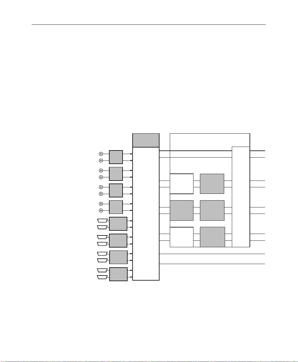
Model 1200 Overview
The Model 1200 architecture (Figure 1-1) consists of a single
mix/effects system with two keyers and a downstream keyer.
Video inputs selected on the background crosspoint buses enter a
pair of program and preview mixers. Video and key inputs
selected on the key crosspoint bus are first processed in the keyer
circuits. If effects send mode is off, the keyer outputs go directly
to the mixers, and any aux bus selections go directly to the aux
outputs. If effects send mode is on, the key and fill outputs of one
of the keyers are routed via the aux bus outputs to a DPM, and the
••••••••••••
••••••••••
••••••••••••
••••••••••
••••••••••••
••••••••••
••••••••••••
••••••••••
••••••••••••
••••••••••
••••••••••••
••••••••••
••••••••••••
••••••••••
••••••••••••
••••••••••
SERIAL
INPUT
OPTION
SERIAL
INPUT
OPTION
SERIAL
INPUT
OPTION
SERIAL
INPUT
OPTION
PARALLEL
INPUT
OPTION
PARALLEL
INPUT
OPTION
PARALLEL
INPUT
OPTION
PARALLEL
INPUT
OPTION
CHROMATTE™
4:2:2/4:4:4 CHROMA
KEY OPTION
CROSSPOINT
MODULE
AUX 1
AUX 2
V
MIX/EFFECTS
KEYER 1
K
V
SECOND
MIX/EFFECTS
K
OPTION
V
DOWNSTREAM
K
PROGRAM BACKGROUND
PRESET BACKGROUND
KEYER CARRIER AND
EFFECTS SEND
MODULE
BORDERLINE
KEY EDGE
GENERATOR
OPTION
BORDERLINE
KEY EDGE
KEYER
KEYER
GENERATOR
OPTION
BORDERLINE
KEY EDGE
GENERATOR
OPTION
Note: Digital video/key inputs and outputs may be
either serial or parallel as specified when ordered.
V
EFFECTS
K
SEND
AND
AUX BUS
SIGNAL
ROUTING
V
K
V
K
Figure 1-1. Model 1200 Simplified Functional Block Diagram
V
K
V
K
V
K
1-4
Page 17
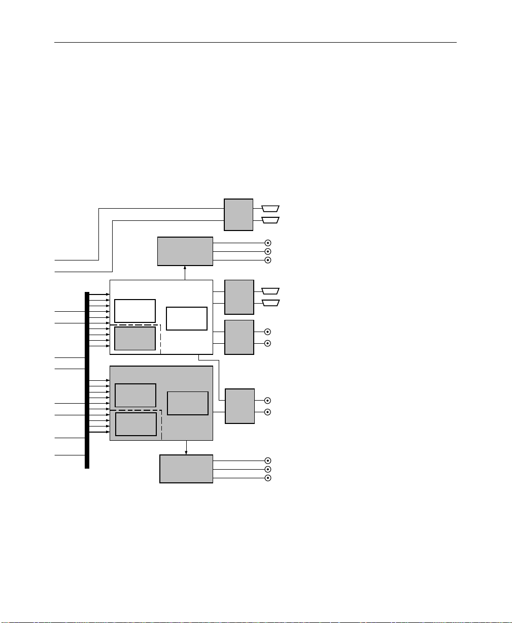
Model 1200 Overview
aux buses automatically select the manipulated key and fill inputs
returning from the DPM. The aux buses then apply the
manipulated key and fill signals to the mixers. The mixers
multiply the processed background and key signals to produce
mixed effects video. The effects video enters the downstream key
mixers where the DSK signal is mixed over the effects layer. The
final output signals then pass through output processing to the
various analog, serial digital, and parallel digital outputs
PGM
EFFECTS
SEND &
AUX BUS
OUTPUT
OPTION
DIGITAL-TO-ANALOG
CONVERTER
OPTION
PROGRAM
MIXER
V
K
V
K
V
K
PST
EFFECTS
MIXER
Z-KEY™ DEPTH
PROCESSOR
OPTION
LOOK-AHEAD PREVIEW
EFFECTS
MIXER
Z-KEY™ DEPTH
PROCESSOR
OPTION
MIXER OPTION
DIGITAL-TO-ANALOG
DOWNSTREAM
KEY MIXER
DOWNSTREAM
KEY MIXER
CONVERTER
OPTION
PARALLEL
PROGRAM
OUTPUT
OPTION
SERIAL
PROGRAM
OUTPUT
OPTION
PREVIEW
&
CLEAN
FEED
OUTPUT
OPTIONS
••••••••••••
••••••••••
••••••••••••
••••••••••
••••••••••••
••••••••••
••••••••••••
••••••••••
SEND VIDEO
OR AUX 1 OUT
SEND KEY
OR AUX 2 OUT
ANALOG
PROGRAM
VIDEO
(YUV, RGB,
OR Y R-Y B-Y)
VIDEO
PGM 1
KEY
PGM 1
VIDEO
PGM 2
KEY
PGM 2
PREVIEW
VIDEO
CLEAN FEED
VIDEO
ANALOG
PREVIEW
VIDEO
(YUV, RGB,
OR Y R-Y B-Y)
1-5
Page 18

Section 1— Introduction
1-6
Page 19

Introduction
2
Startup
This section of the manual helps you get started using the
switcher. The following topics are discussed:
■
System Startup or Restart—page 2–2
■
Concepts You’ll Need to Know—page 2–3
System Setup: Using the Configuration Menus—page 2–12
■
You might be tempted to skip over the “Concepts” part of this
section, especially if you are an experienced switcher operator.
Nevertheless, we advise you to read it anyway because it explains
operating concepts specific to the 1200 switcher that will help you
to more fully understand how the 1200 works.
2-1
Page 20

Section 2— Startup
System Startup or Restart
Startup
1. Set the 0/1 power switch inside the front cover of the switcher
frame to the 1 (on) position.
2. Set the 0/1 power switch inside the switcher control panel to
the 1 (on) position.
This applies power to the entire system, which will boot up and
become operational in a few seconds. To power down the system
at any time, just switch both power switches to 0 (off).
Restart
If the system becomes confused or locks up, you can restart it as
explained below. The effect you were working on will be lost, but
E-MEM contents and configuration files will remain intact.
1. Press the
2. If clearing the panel didn’t help, press the
3. Finally, if neither of the above steps resolves the problem, turn
LampSaver Panel Sleep Mode
Note that the switcher includes a “sleep” mode called LampSaver,
which is intended to extend pushbutton lamp life-span. When the
switcher is idle for an extended period (adjustable) all button
lamps turn off. To wake up the switcher, press any button or turn
any knob. For details about the LampSaver mode, see the
description of the Miscellaneous menu in Section 3.
2-2
[Misc]
control panel. Then press the
button in the Miscellaneous Menu to clear the panel.
the Control module (064911) inside the switcher frame.
the frame and panel power switches off and on again.
menu button in the upper left corner of the
[CLR WORK BUFFER]
RESET
switch on
soft
Page 21

Concepts You’ll Need to Know
There are a few basic concepts that you should know before you
begin setting up and operating the switcher. These concepts are
presented on the following pages.
Delegation
Some switcher functions, when selected, automatically activate
related subpanels or functions. This is called
example, when you press the
subpanel, the Keyer subpanel delegates to control Keyer 1.
Related functions delegate in logical ways, making operation
easier because fewer button pushes are required.
Sometimes, even with the help of automatic delegation, you must
still delegate a function manually. If a subpanel or function
doesn’t respond when you operate it, check that it is delegated to
the function you are trying to control.
Concepts You’ll Need to Know
[Key 1]
delegation
button in the Transition
. For
Crosspoint Bus
A
crosspoint bus
each with a different video or key input and a common output
called a
connecting to the output. The outputs of the various buses feed
the switcher’s effects and transition circuits.
There are a number of buses in the Model 1200, including the
PGM (Program) and PST (Preset) background buses, the Key
buses, and the Aux (auxiliary) buses. The background buses feed
the video mixers, allowing you to select background sources and
do transitions between them. The key buses feed the keyers,
allowing you to set up keys, which are also fed to the mixers for
keying over the background. Lastly, the aux buses select signals
and send them directly to a switcher output for feeding external
devices, such as digital picture manipulators; this makes the same
inputs that are available to the switcher also available to the
external devices.
bus
consists of a group of switches called
. The switches allow you to select an input for
crosspoints
2-3
,
Page 22
Section 2— Startup
Transition
A
transition
Model 1200 provides three methods for making video transitions:
a cut, a mix, and a wipe.
is a change from one video picture or to another. The
Cut Transition
A
cut
is an instantaneous switch from one picture to another. A
background cut, for example, switches the Program (on air)
output of the switcher instantly from the picture selected on the
Program bus to the picture selected on the Preset bus. A cut can
also be used to switch a key on or off air instantaneously.
Mix Transition
A
mix
is a transition from one picture to another where the new
picture mixes into and then replaces the picture that was already
on air (Figure 2-1). The Model 1200 allows you to mix from one
background picture to another or to mix up to three separate key
layers on or off over a background. Background and effects key
mixes can be done separately or simultaneously.
Starting Video
2-4
Ending Video
Mix in Progress
Figure 2-1. A Mix Transition
Page 23
Concepts You’ll Need to Know
Wipe Transition
A
wipe
is a transition from one picture to another where a shaped
edge moves across the screen revealing the new picture (see
Figure 2-2). A background wipe removes the old Program
Background picture as it wipes on the new Preset Background
picture. A key wipe reveals the key over the existing background
or removes it without affecting the existing background. In the
Model 1200, a wipe can also change the background and the
effects key(s) at the same time.
Wipes can take the shape of any of the twenty available patterns,
which can be adjusted for position, aspect ratio, multiples,
rotation, modulation, edge width, edge color, and edge softness.
Starting Video
Ending Video
Wipe in Progress
Figure 2-2. A Wipe Transition
2-5
Page 24

Section 2— Startup
Key
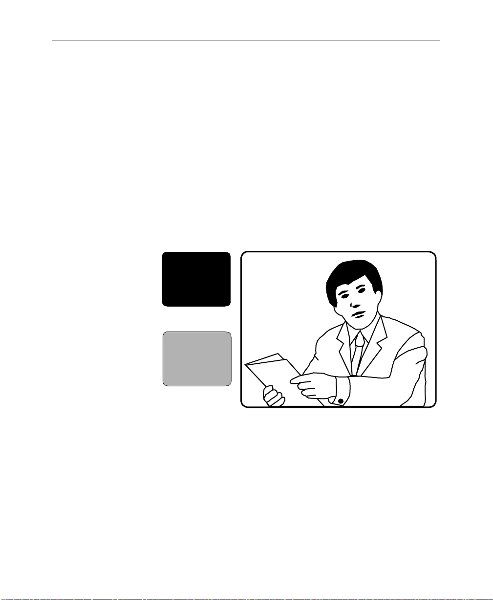
A key is an effect in which parts of one picture are inserted into
another to create a composite picture. For example, keys are used
to insert captions, to place a small news scene or graphic over the
shoulder of a newscaster, or to place the image of a weather
reporter in front of a weather map. There are several types of keys,
each of which serves a different purpose.
Luminance Key
A
luminance key
information in one picture, called the
another picture, called the
fill
, is inserted into the hole to fill it. A
operator to set the level of key source brightness that will cut the
hole so that any part of the picture that is lower in brightness than
the clip setting is ignored and will not cut the hole. The operator
can also
instead of bright areas.
invert
, shown in Figure 2-3, uses the brightness
key source
background
the key so that dark areas of the source cut the hole
. A third picture, called the
clip
to cut a hole in
control allows the
2-6
To use an example, suppose we want to insert a green logo into
some background video. We could print the logo in white on
black paper and then focus a camera on it. We can then apply the
signal from the camera to the switcher’s keyer where it will be
used as a key signal. Next we can select a green matte video to
apply to the keyer as the fill video. When the clip is set properly,
the keyer will ignore the black paper and use only the white logo
shape to cut a hole in the background video. Then it will fill the
logo-shaped hole with green matte video. This creates a green
logo inserted into the background. In actuality, this method of
keying is seldom used anymore. Instead, a graphics system
generates the key and fill video, but the same concepts apply.
Luminance keyers also include a
sharpness of the transition from one picture to another at the key’s
edge; high gain yields a sharp edge, and low gain yields a soft
edge that mixes the fill and background video. In addition, the
Model 1200 keyers include an S-shaping function that prevents
the transition at the key edge from becoming too sharp and
creating what appears to be a band or line around the key.
gain
control, which sets the
Page 25
Concepts You’ll Need to Know
Using the Keyer menu, the clip and gain controls can be changed
to control foreground clip and background clip. In that case, the
controls independently adjust the transition edges of the
foreground fill video and the background video.
Linear Key
A
linear key
key is set to a value of one (also called “unity”) so that the edges
of anti-aliased key sources are faithfully reproduced. Anti-aliased
sources, such as the output of a character generator or graphics
system, have soft edges that produce a mix between the fill and
the background at the key edge. A linear key preserves this edge.
GVG
News
is similar to a luminance key except that the gain of the
GVG
Key Source
News
Fill Video
Background with Key and Fill Inserted
Figure 2-3. Luminance Key Example
2-7
Page 26

Section 2— Startup
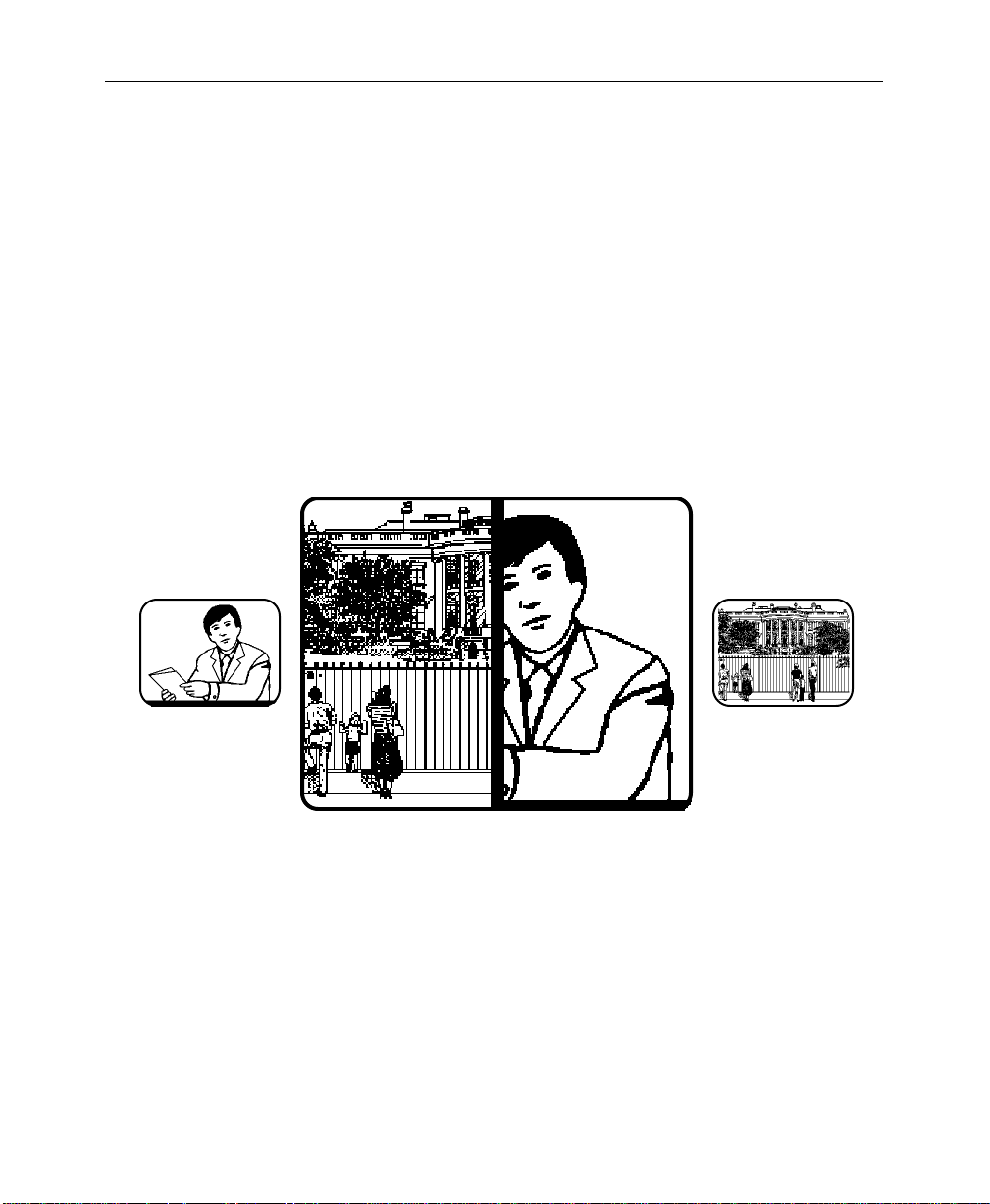
Preset Pattern Key
A
preset pattern key
wipe pattern cuts the hole in the background video. The fill video
is selected on the Key bus, and the Pattern controls and Wipe
menus are used to select and adjust the key source pattern.
or
preset wipe
is a key in which the shape of a
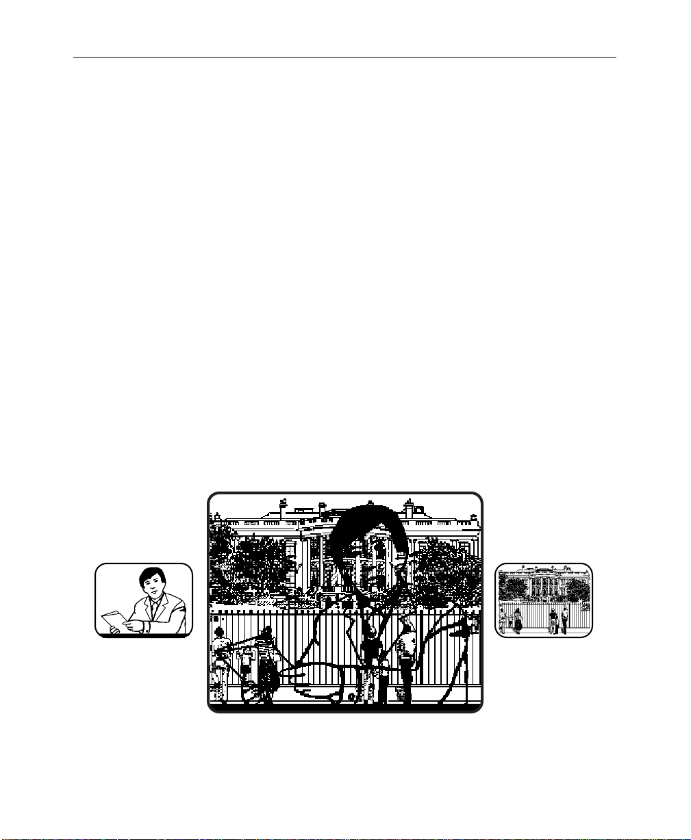
Chroma Key
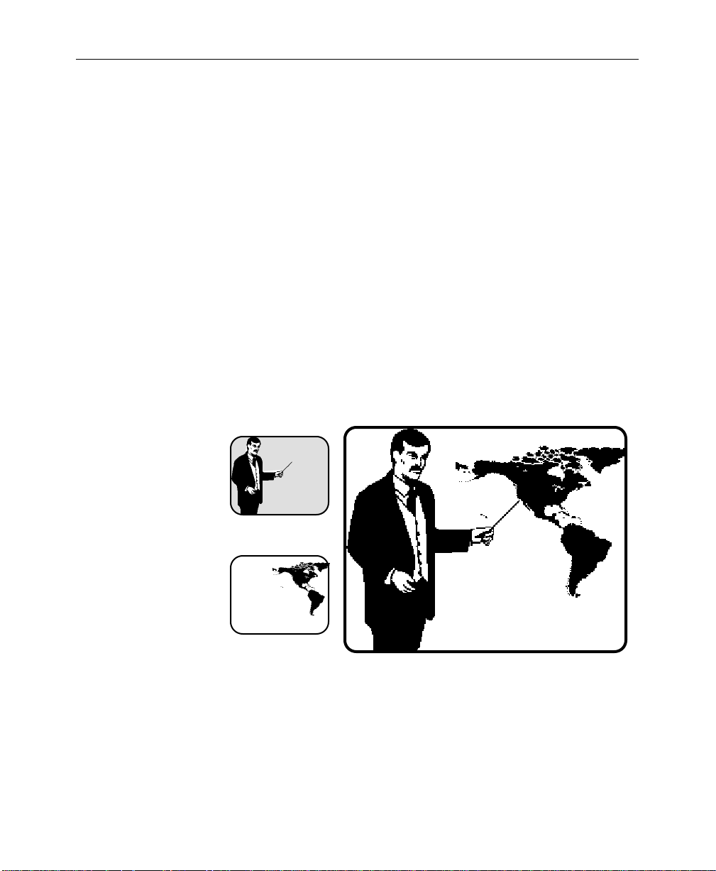
A
chroma key
the background of a scene is detected and replaced with a new
background scene. This gives the illusion that foreground objects
are positioned in front of a new background. For example, the fill
video selected on the Key bus may be a weather reporter standing
in front of a blue wall, and the new background video may be a
weather map (Figure 2-4). The completed chroma key consists of
the weather map background where the blue wall used to be and
the reporter foreground fill everywhere else. This creates the
illusion that the reporter is standing in front of the weather map.
A convenient feature of the 1200 chroma keyer is automatic setup,
which sets up the key for you when you identify the background
color that you want to replace by positioning a cursor over the
color using the joystick and pressing the button on the top of the
joystick. In most cases, this function yields a very good chroma
key, which you can use as is or fine tune as desired using the
Keyer controls and the Chroma Key menu controls.
is a key in which a particular color that you select in
2-8
The Model 1200 chroma keyer includes background and
foreground suppression. Background suppression replaces the
old background color with black before adding in the new
background. This ensures that the old background color is
completely removed from the scene, resulting in a cleaner key.
Foreground suppression is essentially a second chroma keyer that
allows you to detect and remove the background color and its
variations that “splash” onto foreground objects, as sometimes
happens when the foreground object is placed near the
background. The detected foreground “splash” color is replaced
with a neutral color and luminance value that restores the natural
color of the foreground object.
Page 27
Concepts You’ll Need to Know
Both background and foreground suppression include menu
controls for selecting the hue to be replaced and for adjusting the
luminance and chrominance levels in the areas of the picture
where suppression is applied.
Also included in the 1200 chroma keyer are a shadow processor
and a box mask. The shadow processor adjusts the amount of
shadow that chroma key foreground objects cast onto the
background, making the key look more natural. The box mask,
controlled from the Chroma Key Force Mask menu, can be sized
and positioned over a part of the key foreground or background
to prevent the key from occurring in that area.
Lastly, an Edge Control menu allows you to adjust the size (both
width and height) of the key edge in the black suppressed part of
the background. Adjusting for optimum key size ensures that
none of the black background suppression is visible along the key
edges.
BLUE
ForegroundVideo
Background Video
Foreground Keyed Over Background
Figure 2-4. Chroma Key Example
2-9
Page 28

Section 2— Startup
Shaped Video
Shaped video
create a partial-raster image that is matted over black. A good
example of shaped video is the fill video output of some character
generators, which consists of characters on a black matte.
Typically, the shaped fill video is also accompanied by a matching
key signal that may be used in a keyer to cut a hole in background
video into which the already-shaped fill video may be inserted.
The 1200 configuration menus ask you to identify video inputs as
shaped or unshaped because the switcher handles those two types
of fill video signals differently. For keying with shaped fill video,
the keyer multiplies only the background video with the key
signal to cut a hole in the background, and then adds the alreadyshaped fill video into the hole. For fill video that is not already
shaped, the keyer first multiplies both the background and the fill
video with the key to cut a hole in the background and shape the
fill to match the hole. Then the background video and the fill
video are added together to create the finished key.
If you incorrectly identify the type of fill video in the Define
Inputs configuration menu, selecting shaped when you should
select unshaped or vice versa, your keys will have dark lines at the
edges or other artifacts. Changing the video type in the Define
Inputs configuration menu will correct the problem.
is video that has been multiplied by a key signal to
Effects Send
2-10
Effects Send provides a close interface between the switcher and a
digital picture manipulator (DPM). Effects Send takes the key and
fill video outputs of an effects keyer and sends them to the DPM
for manipulation. The manipulated key and fill outputs from the
DPM then re-enter the switcher’s mixers via the aux buses.
The Effects Send advantage lets you transform a switcher key
effect, such as a chroma key or a preset pattern, as though the
DPM circuitry were built into the middle of the switcher: The
transformed key can be layered over a switcher background and
additional keys can be layered on top of the transformed key.
Page 29

Z-Key™ Depth
Concepts You’ll Need to Know
The Depth option enables the switcher’s two effects keyers to key
a depth key input from a Grass Valley digital picture manipulator
over a switcher background. Depth keying creates an effect in
which one key layer appears closer to the viewer than a second
key layer does, and one key layer can “slice” through the other.
The Depth option also works with ordinary key signals. You can
assign different depth values to the two M/E keys and record
them. Then you can play the composite effect back and insert
additional key layers between the original two layers. The keys
cannot be made to intersect, and they may not create the visual
illusion of depth the way a true depth key does, but you can
composite multi-layered graphics with layers that slide in and out
between other layers.
In order to record a depth key, a 10-bit digital recorder with two
channels (video and key) is required to retain depth information.
E-MEM® Effects Memory
E-MEM Effects Memory provides a way of storing switcher effects
for later use. With E-MEM you can set up an effect and “learn” a
snapshot of it into memory. Later, you can recall that effect at the
touch of a button, and the switcher will immediately return to the
state it was in when the effect was learned.
You can also learn automatic transitions as part of a stored effect.
When you learn an auto transition with an effect into a register,
recalling that register recalls the effect first, and then starts the
stored transition automatically.
The E-MEM system includes 20 effects storage registers arranged
in two “banks” of ten registers each. E-MEM register contents can
be saved to disk using the floppy drive and menu display.
2-11
Page 30
Section 2— Startup
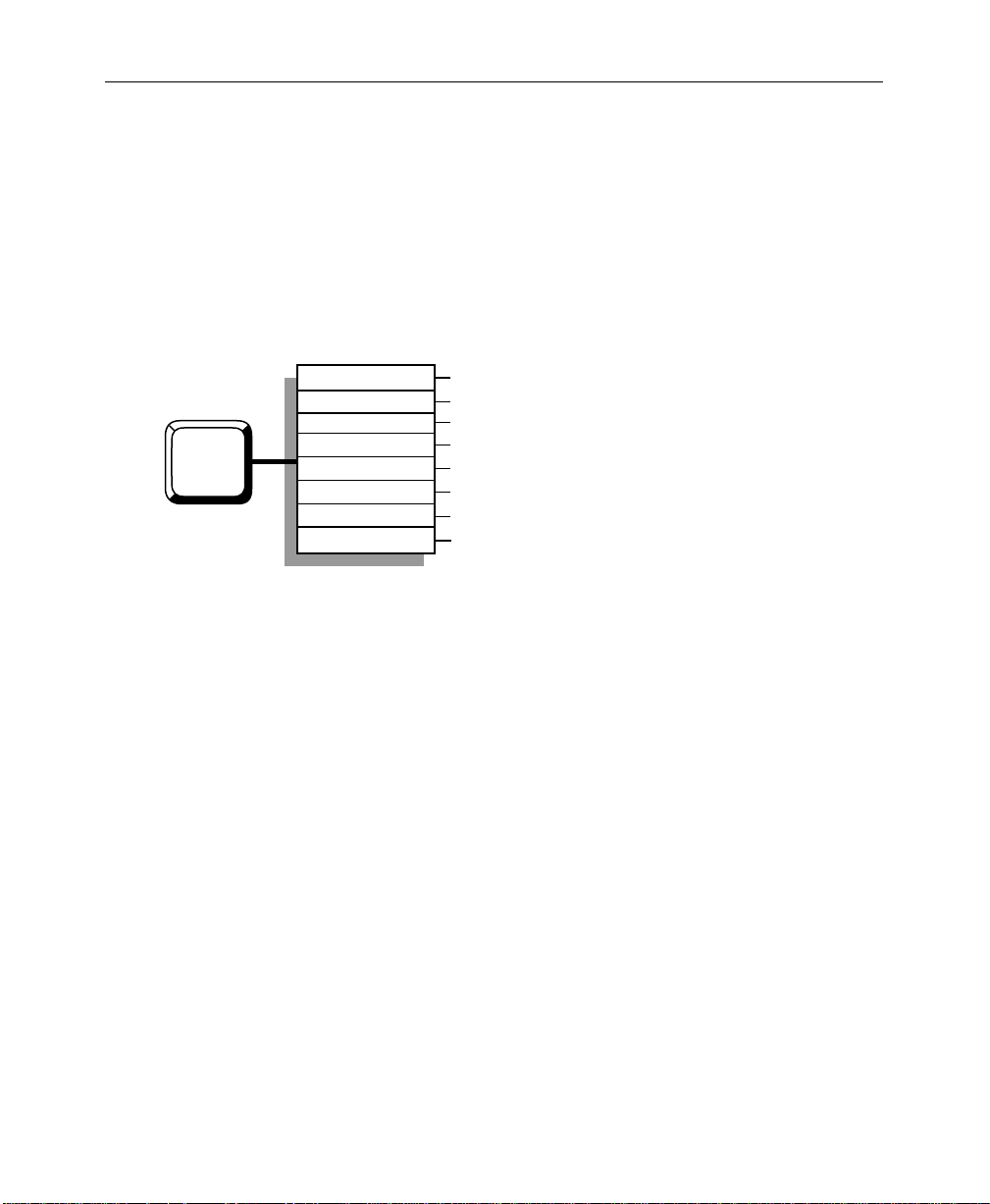
System Setup: Using the Configuration Menus
The following procedures allow you to configure the 1200 system
to your installation. Using the Configuration menus in the menu
display, you can assign sources to the crosspoints, configure the
inputs, set output levels, adjust system timing, and set other
system parameters. These menu items are accessed through the
Configuration menu (Figure 2-5) on the Menu Display subpanel.
System Params
Define Inputs
Crosspoints
CONFG
Outputs
Timing
Ports
GPI
Tally
Figure 2-5. 1200 Configuration Menu Tree
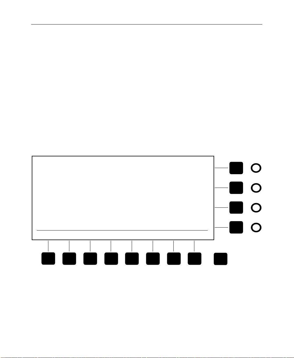
Menu Pushbuttons and Knobs
The display panel includes pushbuttons and knobs that work
interactively with the display menus to control the switcher:
The white menu “hot buttons” at the left of the display
■
activate the top level menus.
■
The black buttons and knobs surrounding the display are
“soft” buttons and knobs that change function with each
menu. Labels displayed along the bottom and right edges of
each menu indicate the functions of the soft controls. The “>”
display symbol indicates a lower level menu that you can
view when you press the associated soft button.
4:3/16:9, Edit Field Dom, System Clock
Define Inputs, Select CK Source, Xpt Legends
Map Inputs to Crosspoints
Configure Outputs
Switcher Timing Adjustment
Serial Port Configuration
GPI Setup
Tally Relay Output Monitoring and Testing
2-12
■
Double-pressing one of the soft buttons next to the soft knobs
restores the associated knob function to its default value.
■
The
[Exit]
button takes you up one menu level.
Page 31

Configuration Menu
System Setup: Using the Configuration Menus
The Configuration menu (Figure 2-6) and its sub-menus allow
you to set up the switcher to meet your requirements. To begin the
setup process, press the
to bring up the Configuration menu, which includes the following
sub-menus and functions.
[Config]
button next to the menu display
CONFIGURATION MENU
[SYSTEM PARAMS>]
—4:3/16:9 Picture Aspect, Editor Field
Dominance, and System Clock.
[DEFINE INPUTS>]
—Define Inputs, Chroma Key Sources,
and Crosspoint Legends.
[XPT MAP]
[OUTPUTS>]
[TIMING>]
[PORTS>]
[GPI>]
[TALLY>]
—Map physical inputs to crosspoints.
—Configure Outputs.
—Switcher Timing.
—Serial Port Configuration.
—GPI Setup.
—Tally Relay Setup.
SYSTEM
PARAMS > OUTPUTS >
DEFINE
INPUTS >
XPT
MAP >
Figure 2-6. Configuration Menu
TIMING >
PORTS >
GPI >
TALLY >
Exit
2-13
Page 32

Section 2— Startup
System Parameters Menu
Use the System Parameters menu (Figure 2-7) as explained below
to set the aspect ratio (ratio of television picture width to height),
to set the field dominance for use with an editor, and to set the
system clock.
1. Press the
[SYSTEM PARAMS>]
soft button to display the
System Parameters menu.
2. Use the
[VIDEO ASPECT]
soft button to highlight the
selection that reads 4:3. Press the button to switch between 4:3
and 16:9.
3. If appropriate, change the Field Dominance using the
[EDITOR FLD DOM]
ODD
or
EVEN
soft button. Setting Field Dominance to
ensures that transitions always take place
during a particular color field. Some editing systems may
require a particular selection; see your editor manual for
details. The default is
4. Set the date by selecting
and turning the soft knobs to select the appropriate
(MONTH)
using the
, and
[CONFIRM DATE]
5. Set the time by selecting
and turning the soft knobs to select the appropriate
(MINUTES)
, and
confirm it using the
BOTH
fields.
DATE
with the
(DAY)
. When the date is correct, confirm it
[SELECT]
soft button.
TIME
with the
(SECONDS)
[CONFIRM TIME]
. When the time is correct,
[SELECT]
soft button.
soft button
(YEAR)
soft button
(HOURS)
,
,
2-14
Page 33

System Setup: Using the Configuration Menus
SYSTEM PARAMETERS MENU
16:9
4:3
VIDEO
ASPECT
BOTH
ODD
EVEN
EDITOR
FLD DOM
Figure 2-7. System Parameters Menu
CLOCK
January 1, 1995
8:30 am
DATE
TIME
SELECT
CONFIRM
CONFIRM
DATE
YEAR
= 1995
MONTH
= JAN
DAY
= 1
Exit
2-15
Page 34

Section 2— Startup
Define Inputs Menu
From the Configuration menu select
[DEFINE INPUTS>]
to
display the Define Inputs menu (Figure 2-8). This menu is
typically configured during switcher installation. However, you
may want to change configurations for different types of
production sessions. The Inputs menu allows you to do the
following:
■ Give each physical input a descriptive name which is carried
forward into several other menu levels.
■ Attach characteristics to each physical input, such as bit
resolution of the source, identification of the signal type, and
association of key cutters with fills. The signal type tells the
switcher whether the input is to be treated as video, shaped
video, key, or key with depth.
■ Designate a video/key pair as the return inputs in systems
where an effects send and return will be used. This
information is needed by the switcher for automatic
switching of the effects loop. (See the explanation of Effects
Send later in this section for details.)
■ Select 4:2:2 chroma key inputs or full-bandwidth 4:4:4 chroma
key inputs. Two physical inputs are needed to accommodate
a full-bandwidth chroma key signal. The Inputs/4:4:4 CK
Sources sub-menu designates those two physical inputs.
2-16
■ Associate a four-character legend with each physical input.
These legends appear in the Inputs menus and also in the LED
displays that may be installed between the Key and Aux
crosspoint pushbutton rows.
Define Inputs
Using the Define Inputs menu, define each input as follows:
1. Select a Physical Input using the
knob. The physical input numbers are the same as the jack
numbers on the back of the electronics frame.
(PHYSICAL INPUT)
soft
Page 35

System Setup: Using the Configuration Menus
2. Enter a Signal Name by pressing the
button, typing a name on the keyboard, and pressing the
[ENTER NAME]
3. Using the
or 10 bit signal.
4. Using the
type:
manipulator),
VIDEO
5. Assign the Effects Return Flag to a video and a key source by
highlighting them and pressing
identifies that video/key input pair as the Effects Send signals
returning from a Digital Picture Manipulator. When Effects
Send is on, the switcher will automatically select these inputs.
6. Assign an Auto Select key input to a video fill input using the
(AUTO SEL KEY SRC)
automatic selection of the associated key input when you
select the fill input on the Key crosspoint bus.
DEFINE INPUTS MENU
PHYSICAL
INPUT
SIGNAL NAME BITS TYPE
J1 VTR 1 10 VIDEO
J2
CHAR GEN VID
CHAR GEN KEY
J3
VTR 2 10
J4
VTR 3
J5
J6 R-VTR
J7
DPM-700 KEY
J8
DPM-700 VIDEO
10
10
10 KEY
10 J7
DEPTH
(unshaped).
SHAPED
8
8
SHAPED
[CLEAR NAME]
. soft button.
[BITS]
[TYPE SELECT]
soft button, identify the input as either an 8
soft button, identify the input
(depth key signal from a digital picture
KEY, SHAPED
(video shaped by a key), or
[EFX RTN FLAG]
soft knob. Auto Select provides
PHYSICAL INPUT
AUTO
SEL
J3
= J2
AUTO SEL
KEY SRC
= J3
KEY
VIDEO
VIDEO
VIDEO
EFFECTS
RETURN
KEY
VIDEO
soft
. This
CLEAR
NAME
ENTER
NAME BITS
DEPTH
8
10
KEY
SHAPED
VIDEO
TYPE
SELECT
EFX RTN
FLAG
4:4:4 CK
SOURCES >
XPT DISP
LEGENDS >
Exit
2-17
Page 36
Section 2— Startup
Figure 2-8. Define Inputs Menu
Chroma Key Sources Menu
Display the 4:4:4 Chroma Key Sources menu (Figure 2-9) by
selecting
To assign a 4:4:4 video fill to the Chroma Keyer, use the soft knobs:
1. Select the Physical Input source for channel A by using the
2. Select the Physical Input source for channel B by using the
[4:4:4 CK SOURCES>]
(4:4:4 CK CHANNEL A)
(4:4:4 CK CHANNEL B)
from the Define Inputs menu.
soft knob.
soft knob.
4:4:4 CHROMA KEY SOURCES MENU
Figure 2-9. 4:4:4 Chroma Key Sources Menu
4:4:4 CK
CHANNEL A
=J15
4:4:4 CK
CHANNEL B
=J16
Exit
2-18
Page 37

System Setup: Using the Configuration Menus
Crosspoint Display Legends Menu
Display the Crosspoint Display Legends menu (Figure 2-10) by
selecting
This menu allows you to assign an unique name (up to 4
characters) to each physical input. The name will display above
the crosspoint column to which that physical input is mapped.
[XPT DISP LEGENDS>]
from the Define Inputs menu.
1. Use the
(PHYSICAL INPUT)
Input. The Signal Name column displays the descriptive
name of the selected Physical Input. (Signal Name is created
in the Define Inputs menu.)
2. To enter a new Local Name, select Local using the
MODE]
soft button, press the
type a descriptive name using the keyboard, and press the
[ENTER LOCAL]
CROSSPOINT DISPLAY LEGENDS MENU
PHYSICAL
INPUT
J1
J2
J3
J4
J5
J6
J7
J8
SIGNAL NAME
VTR 1
CHAR GEN VIDEO
CHAR GEN KEY
VTR 2
VTR 3
R-VTR
DPM-700 KEY
DPM-700 VIDEO
CLEAR
LOCAL
LOCAL
NAME
VTR1
CGV
CGK
VTR2
VTR3
RVTR
DPMK
DPMV
ENTER
LOCAL
soft button.
soft knob to select a Physical
[LEGEND
[CLEAR LOCAL]
PHYSICAL INPUT
= J5
soft button,
Figure 2-10. Crosspoint Display Legends Menu
Exit
2-19
Page 38

Section 2— Startup
Crosspoint Map Menu
The Crosspoint Map menu (Figure 2-11) is displayed by pressing
the [Config] button and then the
[XPT MAP>]
button.
1. Set the
ALTERNATE
[XPT MAP SELECT]
soft button to the
crosspoint map. Using this function, you can
NORMAL
define two completely different crosspoint maps and switch
between them as desired. If you plan to use only one map,
select
NORMAL
2. Use the
(XPT)
.
soft knob to select the crosspoint to be
highlighted.
3. Use the
(PHYSICAL INPUT)
soft knob to assign a Physical
Input to the highlighted crosspoint. The Signal Name column
will display the descriptive name of the selected Physical
Input. (Signal Name is created in the Define Inputs menu.)
or
2-20
Page 39

System Setup: Using the Configuration Menus
CROSSPOINT MAP MENU
PHYSICAL
XPT
INPUT
1 BLACK BLACK
2J1
3J4
4 J6 R-VTR
5 J2 CHAR GEN V
6J3
7
8
9
10 J8
11
12
13
14
J8
J7
J9
J11
J12
MATTE
J16
SIGNAL NAME
VTR 1
VTR 2
CHAR GEN K
DPM-700 VIDEO
DPM-700 KEY
CAMERA 1
CAMERA 2
PAINTBOX
STILL STORE
MATTE
BARS
Figure 2-11. Crosspoint Map Menu
ALTERNATE
NORMAL
XPT MAP
SELECT
XPT
= 5
PHYSICAL INPUT
= J2
Exit
2-21
Page 40

Section 2— Startup
Outputs Menu
OUTPUTS MENU
OUTPUT NAME
PROGRAM 1 10 OFF
PROGRAM 2
PREVIEW
CLEAN FEED
KEY OUT 1
KEY OUT 2
AUX 1
AUX 2
PROGRAM DAC
PREVIEW DAC
From the Configuration menu, select
[OUTPUTS>]
to display the
Outputs menu (Figure 2-12). This menu allows you to set up
signal formats for Model 1200 outputs.
1. Use the
(OUTPUT)
soft knob to highlight the name of the
output to be configured.
2. Use the
[BITS RES]
soft button to select either 8 or 10 bits to
match the bit resolution of your output destination.
3. Use the
for that output. Shaping
[SHAPING]
soft button to turn shaping ON or
ON
produces a video output shaped
by the key signal and matted over black. (Shaping for the
Program and Preview DAC outputs follows the Program 1/2
or Clean Feed output shaping selection.)
4. Use the
feed; video with no key) or
BITS
RES
SHAPING
10
10 ON
10
10
10
8
10
-
-
[SIGNAL SOURCE]
SIGNAL
SOURCE
OFF
ON
ON
ON
OFF
OFF
-
-
-
-
PROGRAM
CLEAN
-
-
PROGRAM
PROGRAM
to select either
PROGRAM
OUTPUT
CLEAN
(video with key).
OFF
(clean
2-22
8
10
BITS
RES
ON
OFF
SHAPING
CLEAN
PROGRAM
SIGNAL
SOURCE
Figure 2-12. Outputs Menu
Exit
Page 41

Timing Menu
System Setup: Using the Configuration Menus
Input timing is automatic; however, you can adjust the overall
timing manually in the Timing menu (Figure 2-13) to ensure that
auto-timing captures all inputs. When you make this adjustment,
you are advancing or delaying the Reference input, which causes
a corresponding movement of the auto-timing capture window
for the primary inputs and also causes a corresponding
movement of the switcher outputs.
TIMING
INPUT
J1
J2
J3
J4
J5
J6
J7
J8
CLOCKS
+28
-56
+170
-210
-300
+250
-40
+80
To adjust the overall timing, use the
rough timing value, then adjust the
[COARSE]
soft knob to set a
[REF TIMING (FINE)]
knob to fine tune the timing. The maximum timing range is ±330
clocks (a clock equals 69.84 nanoseconds).
REF TIMING (FINE)
µS
2.04
4.07
12.36
15.27
21.82
18.18
2.91
5.82
MAXIMUM TIMING RANGE = +/- 330 CLOCKS
INPUT
J9
J10
J11
J12
J13
J14
J15
J16
CLOCKS
+180
-90
-315
+48
+10
0
-200
+30
13.09
22.90
14.54
µS
6.54
3.49
0.73
0.00
2.18
= +170 CLOCKS
COARSE
Exit
soft
Figure 2-13. Timing Menu
2-23
Page 42

Section 2— Startup
Port Menu
The Port Configuration menu (Figure 2-14) is displayed by
pressing the [Config] button on the main subpanel and then the
[PORTS>]
soft button.
1. Use the
(PORT)
soft knob to highlight the port you wish to
configure. (Ports are listed in the left-most display column.)
2. Use the
(PROTOCOL)
soft knob to select the protocol for the
port. Protocol settings for typical equipment are listed below:
Panel Port —Already set for
1200 PNL
protocol (RS-422,
address 30H, 38400 baud, 8 bits, 1 stop bit, odd parity).
Cannot be changed.
Terminal (TTY) Port —Use
TERMINAL
protocol (RS-232,
9600 baud, 8 bits, 1 stop bit, no parity).
Modem Port —Use
MODEM
protocol (RS-232, 2400 baud, 8
bits, 1 stop bit, no parity).
DPM-100/700 Port —Use
DPM
protocol (RS-422, address
30H, 38.4 K baud, 8 bits, 1 stop bit, odd parity).
Editor Port —Use
Grass Valley
1200
(address 30H).
Communication is RS-422, 38.4K baud, 8 bits, 1 stop bit, odd
parity. You may also use
110
or
200
switcher protocol if your
editor does not have a 1200 interface, but functionality will be
reduced.
Aux Satellite Panel Port —Use
200
or
1200 AUX
(RS-422, 9600 baud, 8 bits, 1 stop bit, no parity). Any available
port may be used for the Aux Satellite Panel.
protocol
2-24
Page 43

System Setup: Using the Configuration Menus
3. If assigning a particular protocol does not yield the correct
communication parameters, you may highlight and change
those parameters individually. Use the
(BAUD RATE)
[STOP BITS]
soft knobs and the
menu buttons.
(ADDRESS)
[BITS], [PARITY]
and
, and
4. The
port to its factory-assigned protocol.
PORT CONFIGURATION MENU
BAUD
PORT PROTOCOL
TTY
TERMINAL
PANEL
1200 PNL
MODEM
EDITOR
FACTORY
DEFAULT
DPM
MODEM
1200
DPM
ADDR
00
30
00
30
30
RATE
9600
38.4K
2400
38.4K
38.4K
Figure 2-14. Port Configuration Menu
[FACTORY DEFAULT]
BITS PARITY
8
NONE
8
ODD
8
NONE
8
8
8
7
BITS
ODD
ODD
ODD
NONE 1
PARITY
soft button resets the selected
STOP
BITS
1
1
1
1
1
2EVEN
STOP
BITS
PORT
PROTOCOL
= MODEM
ADDRESS
= 00
BAUD RATE
= 2400
Exit
2-25
Page 44

Section 2— Startup
GPI Menus
The GPI Inputs menu (Figure 2-15) is displayed when you press
the [Config] top menu button followed by the
[GPI>]
soft button.
From this menu, you can view the GPI Inputs or access the GPI
Outputs menu (Figure 2-16). Together, these two menus allow
you to assign, view, and test the 8 GPI inputs and 8 GPI outputs.
GPI inputs are trigger signals that come from external equipment
(via the GPI connector at the back of the frame) and start a
specified event in the switcher, such as an auto transition. GPI
outputs are trigger signals generated by switcher events that go
out via the GPI connector to external devices to cause them to take
some action. You can assign events to the GPI Inputs or Outputs
as follows:
1. Display the GPI Input or Output menu.
2. Change the event assigned to a GPI using the
INPUT/OUTPUT)
soft knob to highlight the desired input or
(SELECT GPI
output.
Use the
(SELECT EVENT)
soft knob to assign an event to the
3. Highlighted GPI.
Two events deserve special mention. The
MAP
selection allows you to use a GPI input to switch between
ALTERNATE XPT
two different crosspoint maps stored in the Input Map menu. This
can be convenient when you have two different uses for the
switcher, for example, a live news show and off-line post
production. The
AUX BUS TALLY BACK
selection uses the GPI
as an input condition that the switcher detects in order to tally the
selected aux bus crosspoint. This permits an external DPM to tally
the aux buses when aux bus video is on air at the DPM. Aux
tallyback can be turned on and off in the Tally menu.
When set to ON, the
[GPI OUTPUT TEST]
soft button in the GPI
Outputs menu cycles through the GPI outputs, closing each relay
for approximately 1/2 second, allowing you to verify GPI
operation. When finished testing, set the button to
OFF
.
2-26
Page 45

System Setup: Using the Configuration Menus
GPI INPUTS
GPI
INPUT #
STATE EVENT
OPEN
1
OPEN
2
CLOSED
3
CLOSED
4
OPEN
5
OPEN
6
OPEN
7
OPEN
8
GPI Inputs are ENABLED
GPI OUTPUTS
GPI
OUTPUT #
STATE EVENT
1
OPEN
2
OPEN
3
CLOSED
4
CLOSED
5
OPEN
6
OPEN
7
OPEN
8
OPEN
EFFECT CUT
EFFECT AUTO TRAN
DISK CUT
E-MEM 1 LEARN
E-MEM RECALL
AUX 1 TALLY BACK
EFFECT KEY 1 CUT
AUX 2 CROSSPOINT 3
Figure 2-15. GPI Inputs Menu
EFFECT CUT
EFFECT AUTO TRAN
DISK CUT
E-MEM 1 LEARN
E-MEM RECALL
AUX 1 TALLY BACK
EFFECT KEY 1 CUT
AUX 2 CROSSPOINT 3
GPI INPUT
GPI
OUTPUTS>
GPI OUTPUT
SELECT
= 4
SELECT
EVENT
= 10
SELECT
SELECT
EVENT
= 10
Exit
= 4
GPI Outputs are ENABLED
ON
OFF
GPI OUTPUT
TEST
Exit
2-27
Page 46

Section 2— Startup
Tally Menu
Figure 2-16. GPI Outputs Menu
The Tally menu (Figure 2-17) displays a table listing the 16
physical signal inputs, indicating those that are high-tallied by
highlighting them.
The
AUX TALLY BACK
(Aux Bus Tally Back)
ON/OFF
selection,
when set to ON, allows use of a GPI to tally Aux Bus 1 whenever
the effects send fill crosspoint is tallied and Aux Bus 2 whenever
the effects send source crosspoint is tallied. This provides tally
back for an external DPM without requiring a tally back input
from the DPM. To use this feature, it must be enabled in the Tally
menu and assigned as an event to a GPI input in the GPI Inputs
menu.
The
T ALL Y TEST
relays. To test all of the tally outputs, set the
selection allows you to test the tally output
[TALLY TEST]
soft
button to the ON position; this cycles each output on for about
1/2 second. When finished testing, set the button to
OFF
.
TALLY MENU
PHYSICAL
INPUT
BLACK BLACK
J1
J4
J6 R-VTR
J2 CHAR GEN V
J3
J8
2-28
SIGNAL NAME
VTR 1
VTR 2
CHAR GEN K
DPM-700 VIDEO
AUX TALLY
ON
OFF
BACK
PHYSICAL
INPUT
J7 DPM-700 KEY
J9
J8
J11
J12
MATTE
J16
ON
OFF
TALLY
TEST
SIGNAL NAME
CAMERA 1
CAMERA 2
PAINTBOX
STILL STORE
MATTE
BARS
Exit
Page 47

Introduction
3
Controls & Menus
This section describes the Model 1200 control panel, covering each
panel control in detail. Controls are grouped by panel sections,
which are presented in alphabetical order as listed below:
■ Bus Delegates—page 3-4
■ Crosspoint Buses—page 3-5
■ Downstream Keyer (DSK)—page 3-9
■ Effects Send—page 3-11
■ E-MEM—page 3-12
■ External I/F—page 3-15
■ Fade To Black—page 3-16
■ Keyer—page 3-17
■ Matte—page 3-26
■ Pattern—page 3-28
■ Readout Display Options—page 3-116
■ Transition—page 3-32
■ Visual Display and Menus—page 3-36
For your reference, Figure 3-1 shows the control panel.
3-1
Page 48

Section 3 — Controls & Menus
Misc
Config
Chroma
Keyer
Key
Prior/
Proc
Depth
Amp
Stat
Wipe
Copy/
Swap
Disk
Last
Menu
Model
DIGITAL
1
200
Exit
3-2
External Interface
Aux
Key
PGM
PST
Cam
Black DPM
1
Cam
Black DPM
1
Cam
Black DPM
1
Cam
Black DPM
1
Cam
2
Cam
2
Cam
2
Cam
2
Cam
3
Cam
3
Cam
3
Cam
3
VTR
1
VTR
1
VTR
1
VTR
1
VTR
2
VTR
2
VTR
2
VTR
2
Figure 3-1. Model 1200 Control Panel
VTR
3
VTR
3
VTR
3
VTR
3
Editor
Enable
DPM
1
DPM
1
DPM
1
DPM
1
GPI
DPM
Enable
Enable
Routr
1
2
Routr
1
2
Routr
1
2
Routr
1
2
2
Routr
2
Routr
2
Routr
2
3
Routr
3
Routr
3
Routr
3
Routr
Routr
BkgdRoutr
4
RTD1TK 1GF 2GF 1
4
4
4
Uncal
Uncal
BkgdRoutr
BkgdRoutr
BkgdRoutr
Key 1
Uncal
Key 2
Uncal
DSK
Uncal
Uncal
Page 49
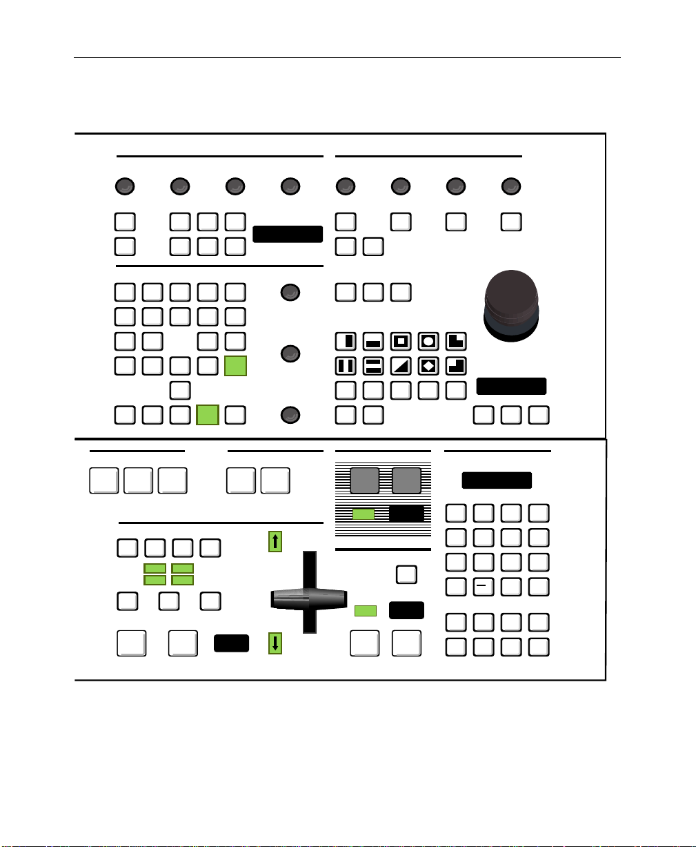
Introduction
Matte
Pattern
Lum Sat OpacityHue Size Width Softness Symmetry
Border
Bkgd
Wipe
Border
Preset
Fill
Key
1
Line
Border
DSK
BKGD 14BKGD 14
Delegation
Key
2
Mask/
Preset
Invert
Mask/
Preset
Pattern
Border
Wipe
Soft
Keyer
Normal
Wipe Direction
User
1
Learn
User
Wipe
Reverse
Undo
Flip
Flop
User
2
User
User
3
Menu
4
Border
Normal
Key
Over
Video
Fill
Linear
Key
Key
1
Shadow
Mask
Matte
Fill
Luma
Chroma
Key
Key
Auto
Setup
DSK
Key
2
Outline
Extrude
Invert
Auto
Video
Select
Key
Key
Preset
Split
Pattern
Key
Key
Cut
On
Key Opacity
Gain
Clip
Effects Send
Key
1
Bus Delegates E-MEM
Aux
DSK
Key
2
Aux
2
1
Fade To Black
Black
Cut
Black
On
Black
Mix
6060
Learn
Transition
Bkgd
Key1Key
2
Key On Key On
Over Over
Trans
Wipe
Mix
Cut
Auto
Trans
Preview
60
DSK
DSK
Cut
Bank
DSK
Preview
BSK
On
DSK
Mix
60
1
Bank
0
+ /---
Clear M/E
Symm
WIPEWIPE
Pos
Center
15
8
7
4
123
Undo
.
Trans
9
56
Enter
0
DSK
Black
Trans
Trans
3-3
Page 50

Section 3 — Controls & Menus
Bus Delegates
The Bus Delegates section of the panel (Figure 3-2) includes the
[AUX 1] and [AUX 2] pushbuttons, representing the two internal
Auxiliary crosspoint buses. When you select one of these buttons,
the Aux crosspoint row delegates to control the selected bus. Only
one of the Aux buttons may be on at a time. Also, turning on an
Aux Delegate button cancels Effects Send if it was on.
Bus Delegates
Aux
1
Aux
2
Figure 3-2. Bus Delegates Panel
3-4
Page 51

Crosspoint Buses
Crosspoint Buses
The crosspoint buses include crosspoint buttons for selecting
video and key sources for backgrounds, keys, and auxiliary bus
outputs. See Figure 3-3 on page 3-6. The crosspoints operate as
follows:
■ Video and key input sources are “mapped” or assigned to
crosspoint columns in the Config/Crosspoint Map menu. In
addition, inputs are defined and assigned names in the
Config/Define Inputs menu.
■ To select an input on any bus, press the [CROSSPOINT]. The
selected input will be routed to the bus output.
■ Crosspoints light brightly (high tally) when contributing to
the on-air Program picture. They light dimly (low tally) when
selected but not on-air.
■ Each crosspoint can generate its own internal matte instead of
selecting a video or key signal, if so assigned in the
configuration menus. To adjust the color of a BKGD or matte,
press the [CROSSPOINT] button to delegate the Matte controls
and then adjust the Matte controls for the desired color.
■ Each crosspoint bus includes an adjustable signal processing
amplifier if enabled in the configuration menus. When you
double-press a video or key crosspoint, the Proc Amp menu
appears, allowing you to adjust signal levels for that video or
key source. As you adjust levels, the UNCAL lamp at the end of
the bus lights to indicate that the proc amp is no longer at the
default unity setting. To reset the proc amp to the default
unity setting, press the
[CLEAR PROC AMP]
menu button,
or hold the crosspoint button down and press the [CLEAR]
button in the E-MEM panel area.
3-5
Page 52

Section 3 — Controls & Menus
PST (Preset) Bus
PST bus crosspoints select the background video that will be
placed on air by the next background transition.
PGM (Program) Bus
PGM bus crosspoints select the background video that is on air at
the switcher’s Program output.
■ You can select a PGM crosspoint directly; this causes an
immediate cut to the new video.
■ Or you can select a source on the PST bus and then do a
background transition to transfer the Preset selection to
Program.
At the end of a background transition the PGM and PST selections
“flip-flop”—the PST source transfers to PGM, and the PGM
source transfers to PST.
3-6
Aux
Key
PGM
PST
Black
Black
Black
Black
Cam
1
Cam
1
Cam
1
Cam
1
Cam
2
Cam
2
Cam
2
Cam
2
Cam
3
Cam
3
Cam
3
Cam
3
1
VTR
1
VTR
1
VTR
1
2
VTR
2
VTR
2
VTR
2
3
VTR
3
VTR
3
VTR
3
1
DPM
1
DPM
1
DPM
1
DPM
VTR
VTR
VTR
Figure 3-3. Crosspoint Buses
DPM
2
DPM
2
DPM
2
DPM
2
Routr
1
Routr
1
Routr
1
Routr
1
Routr
2
Routr
2
Routr
2
Routr
2
Routr
3
Routr
3
Routr
3
Routr
3
BkgdRoutr
4
RTD1TK 1GF 2GF 1
BkgdRoutr
4
BkgdRoutr
4
BkgdRoutr
4
Uncal
Uncal
Key 1
Uncal
Key 2
Uncal
DSK
Uncal
Uncal
Page 53

Key Bus
Crosspoint Buses
Key bus crosspoints select the fill video and key source used by
the delegated keyer to create a key. Each crosspoint can be
assigned a fill video and a key source via the configuration menus.
■ Before selecting a crosspoint, you must first delegate a keyer
by pressing the [KEY 1], [KEY 2], or [DSK] button in the Keyer or
Transition section. Then select a crosspoint and make any
other desired Keyer selections and adjustments.
■ When [VIDEO KEY] is on, the switcher does a self key: the fill
video you select on the Key bus also serves as the key source
(cuts the hole and fills it).
■ When [AUTO SELECT KEY] is on, you select the fill video
crosspoint on the Key bus, and the switcher will automatically
select the assigned key source.
■ You can also do a split key (use different fill and source
crosspoints): Select a Key bus fill [CROSSPOINT], hold down
the [AUTO SELECT KEY] or [VIDEO KEY] button, and select
another Key Bus [CROSSPOINT] to serve as the key source. The
fill button and SPLIT KEY lamp light up and remain lit; the
source crosspoint lights whenever you hold down the [AUTO
SELECT KEY] or [VIDEO KEY] button.
A split key is temporary and does not change the key
assignments mapped in the configuration menus during
system setup. To cancel the split, press any Key bus
[CROSSPOINT] or hold down [Auto Select Key] or [Video Key]
and press the fill [crosspoint].
■ Every Key bus crosspoint has Key Memory, if enabled in the
Keyer menu. When you select a crosspoint, Key Memory
restores the last keyer setup used for that crosspoint.
Remembered functions include key source type (Video or
Auto); key type (Linear, Luma, Chroma or Preset Pattern);
and the various control knob and menu settings.
3-7
Page 54

Section 3 — Controls & Menus
Aux Bus 1 and Aux Bus 2
The single row of Aux bus crosspoint pushbuttons controls two
separate auxiliary crosspoint buses, Aux bus 1 and Aux bus 2. The
Bus Delegate buttons control delegation of the aux row to control
Aux bus 1 or Aux bus 2. After delegating the Aux row to the
desired Aux bus, selecting a crosspoint in the Aux row causes the
corresponding Aux 1 or Aux 2 bus output to cut to new video.
When one of the Effects Send buttons is selected, the Bus Delegate
buttons turn off, and both aux buses become dedicated to the
Effects Send signals. The Aux buses then serve as the return input
path for preprocessed switcher video and key signals that have
been looped through an external digital picture manipulator
before entering the keyer. The switcher automatically selects the
correct aux crosspoints according to the Effects Send crosspoint
map assigned in the configuration menu.
Satellite Aux Bus Panels
3-8
When an optional Model 1200 or Model 200 Satellite Aux Bus
Panel is connected to a switcher serial port and enabled in setup,
the satellite panel has direct control over the aux buses. To select
an aux crosspoint on the Satellite Panel, delegate an aux bus by
selecting [AUX 1] or [AUX 2] and then select a Satellite Panel
[CROSSPOINT]. Eighteen of the available Satellite crosspoints are
assigned to the same video, key, black, and background inputs as
the other switcher buses. The remaining crosspoints can have
mattes assigned.
Page 55

Downstream Keyer (DSK)
The DSK (Figure 3-4) inserts titles or other keys on top of the
switcher’s background and effects key layers. The DSK is a fullfunction keyer, capable of luminance, linear, chroma, and preset
pattern keys just like the effects keyers.
■ To delegate Keyer and Key bus controls to the DSK, select
[DSK] in the Keyer section or select [DSK PREVIEW] on the DSK
panel. The DSK lamp at the end of the Key bus will light.
■ Select key fill and source [CROSSPOINTS] using the Key bus.
■ Select and adjust key parameters using the Keyer controls.
■ Transition the key on and off using the [DSK CUT] or [DSK MIX]
button or using the [CUT] button in the Keyer section. When
the key is on, the DSK ON lamp lights.
Downstream Keyer (DSK)
DSK
DSK
Preview
DSK
On
DSK
Cut
Figure 3-4. Downstream Keyer (DSK) Panel Section
60
DSK
Mix
3-9
Page 56

Section 3 — Controls & Menus
DSK Preview
When you select [DSK PREVIEW], the preview monitor option
displays the downstream key over the current Program
background, and the Keyer and Key bus delegate to the DSK.
DSK Cut
When you press the [DSK CUT] pushbutton, the downstream key
immediately cuts on air (or off if it was already on).
DSK Mix
When you press the [DSK MIX] button, the downstream key mixes
on over the Program output (or off if it was already on) at the
frame rate shown in the DSK Transition Rate display. If you press
the button a second time during a transition, the key transition
will reverse.
3-10
Page 57

Effects Send
Effects Send
The Effects Send panel section includes three buttons to enable the
Effects Send option for any one of the three keyers: [KEY 1], [KEY 2],
or [DSK]. See Figure 3-5.
When you select an Effects Send keyer button, Effects Send mode
turns on for the selected keyer, the Keyer controls delegate to the
selected keyer, and the Aux buses delegate to Effects Send. Only
one keyer can use Effects Send mode at a time. This mode routes
the key and fill video outputs of the keyer outside the switcher to
a digital picture manipulator (DPM), which transforms them and
returns them to the switcher’s mixer via the aux buses.
■ To cancel Effects Send, press either of the Bus Delegates
buttons, [AUX 1] or [AUX 2]. This turns off Effects Send and
delegates the Aux row to the selected Aux bus.
Effects Send
Key
1
Key
2
DSK
Figure 3-5. Effects Send Panel Section
3-11
Page 58

Section 3 — Controls & Menus
E-MEM Effects Memory
Twenty E-MEM® effects memory registers store switcher effects
and automatic transitions for later recall. The twenty registers are
divided into two banks of ten registers each. See Figure 3-6.
Learn Button
The [LEARN] button places the E-MEM system in learn mode when
lit and recall mode when off. At the end of a learn, the [LEARN]
button turns off automatically.
E-MEM
15
3-12
Learn
7
4
8
9
56
123
Undo
+ / ---
Clear
Bank
M/E
Trans
.
0
DSK
Trans
Enter
Black
Trans
Figure 3-6. E-MEM Panel Section
Page 59

Register Buttons
E-MEM Effects Memory
The ten register buttons, numbered 0–9, control the twenty paneloperated E-MEM storage registers and also serve as a numerical
keypad. The register buttons operate as follows:
To learn (store) the current switcher setup into an E-MEM register,
press [LEARN], press [BANK] and [0] or [1] if you need to change
banks, and press a register button [0-9]. The current switcher setup
will be stored in that register for later recall.
■ To recall a stored setup, press [BANK] and [0] or [1] if you need
to change banks, and then press one of the register buttons
[0-9]. The setup stored in that register will be recalled.
■ To learn one or more automatic transitions into a register:
Select [LEARN], press the transition functions you want to store
(M/E TRANS], [DSK TRANS], or [BLACK TRANS]), press [BANK] and
[0] or [1] if you need to change banks, and press one of the ten
register buttons [0-9].
The transitions you specified will be stored in the register
together with the current panel setup. When you recall the
register, the panel setup will be recalled and then the
transitions will occur at the rates present when learned.
Undo/Decimal Point
Pressing the [UNDO/.] button immediately after a recall, returns the
switcher to the state it was in just before the recall occurred.
Pressing [UNDO/.] again returns you to the recalled effect. Pressing
[UNDO/.] repeatedly, toggles between the two states.
Pressing [UNDO/.] just after completing a learn restores the
previous contents of the register affected by the learn.
3-13
Page 60

Section 3 — Controls & Menus
Trans Buttons
Using the three Trans buttons, you can assign automatic transition
rates for M/E, DSK, and Black transitions:
■ Press one of the trans buttons: [M/E TRANS], [DSK TRANS], or
[BLACK TRANS]. The E-MEM display will prompt you with
“Trans =?”.
■ Use the keypad to enter a transition rate in television frames.
■ Press [ENTER] to confirm the new rate. The new transition rate
should appear in the appropriate transition rate display.
Clear
■ When used in conjunction with other buttons the [CLEAR]
button resets the selected functions to their default values. To
clear a function to its default values, hold down the button for
that function and press [CLEAR]. If you double press the
[CLEAR] button, the menu display brings up the Misc. menu.
3-14
Page 61

External Interface
Editor Enable
GPI Enable
External Interface
The External Interface pushbuttons (Figure 3-7) are independent
toggle on/off functions that turn editor, GPI, and peripheral bus
communication on or off.
When on (lit), the [EDITOR ENABLE] button turns on
communication via all switcher serial ports configured as Editor
ports. When [EDITOR ENABLE] is off, the switcher ignores input
commands from devices connected to the serial ports.
When on (lit), the [GPI ENABLE] button turns on GPI input control
of the switcher. When [GPI ENABLE] is off, the switcher ignores GPI
inputs from external devices but GPI outputs still function.
DPM Enable
When on (lit), the [DPM ENABLE] button turns on serial port
communication with an external digital picture manipulator
(DPM). When [DPM ENABLE] is off, communication with the DPM
is disabled.
External Interface
Editor
Enable
GPI
Enable
DPM
Enable
Figure 3-7. External Interface Panel Section
3-15
Page 62

Section 3 — Controls & Menus
Fade To Black
The Fade To Black controls (Figure 3-8) allow the Program output
of the switcher to be cut or faded to black and up from black. The
BLACK ON indicator lights when black is partly or fully on. When
black is fully on, all switcher levels, including the DSK, are
covered up by black, and the crosspoints go to low tally.
Black Cut
Pressing the [BLACK CUT] button cuts the switcher Program output
to black. Pressing it again cuts black off.
Black Mix
Pressing the [BLACK MIX] button fades the entire switcher Program
output to black (or up from black if it was already faded) at the
frame rate shown in the Fade To Black transition rate display.
3-16
■ The button lights for the duration of the fade and remains lit
as long as the output is in black.
■ If you press the button a second time during a fade (up or
down), the fade will reverse.
Fade To Black
Black
Cut
Black
On
Figure 3-8. Fade To Black Panel
Black
Mix
60
Page 63

Keyer
The Keyer panel (Figure 3-9) delegates to control any one of the
three keyers and allows you to choose the key type, key source
and fill, key modifiers, and make adjustments.
Keyer Delegation Pushbuttons
The [KEY 1], [KEY 2], and [DSK] Keyer panel buttons delegate the
Keyer panel to control either Keyer 1, Keyer 2, or the Downstream
Keyer (DSK). Only one button may be selected at a time.
Keyer
Keyer
Normal
Key
Over
Video
Fill
Linear
Key
Key
1
Border
Mask
Matte
Fill
Luma
Key
Key
2
Shadow
Force
Mask
Chroma
Key
Auto
Setup
DSK
Extrude
Invert
Video
Key
Preset
Pattern
Key
On
Outline
Show
Key
Auto
Select
Key
Split
Key
Cut
Figure 3-9. Keyer Panel
Key Opacity
Gain
Clip
3-17
Page 64

Section 3 — Controls & Menus
Key Source Type: Video Key and Auto Select Key
The [VIDEO KEY] and [AUTO SELECT KEY] pushbuttons select the
type of key source that will cut a hole in background video to
create a key effect. Only one of these buttons may be on at a time.
The [VIDEO KEY] button enables a self key in which the fill video
selected on the Key bus serves as its own key source.
The [AUTO SELECT KEY] pushbutton enables automatic key source
selection for the fill video that you have selected on the Key Bus.
In this mode, you select the fill video crosspoint, and the source
that will be used automatically is the one that was preassigned for
use with that fill video in the configuration menus.
Split Key
You can do a split key (use different fill and source crosspoints)
for either key source type. To split the key:
■ Select a Key bus fill [CROSSPOINT].
3-18
■ Turn on and hold down either the [VIDEO KEY] button or the
[AUTO SELECT] button. [VIDEO KEY] uses the fill from the
second Key bus crosspoint that you select as the key source.
[AUTO SELECT] uses the auto select key source from the second
crosspoint that you select as the key source.
■ Select another Key Bus [CROSSPOINT] to serve as the key
source.
The split source crosspoint lights when you select it, and lights
whenever you hold down the [VIDEO KEY] or [AUTO SELECT]
button. In addition, the Split Key lamp turns on to indicate a split
key.
To turn off a split key, press any Key bus [CROSSPOINT], or turn off
the current key source type by pressing the other source type
button.
Page 65

Key Fill: Video or Matte
Using the [VIDEO FILL] and [MATTE FILL] buttons you can choose to
fill the key with video or matte. Only one of the two buttons can
be selected at a time. In either case, the signal is supplied by
selecting a Key bus crosspoint that has been designated as a video
fill or a matte fill.
Key Type: Linear Key, Luma Key, Chroma Key, and Preset Pattern
For any of the switcher’s three keyers you can select from among
four key types: [LINEAR KEY], [LUMINANCE KEY], [CHROMA KEY]
(optional), and [PRESET PATTERN]. Only one of these types can be
selected at time. Double-pressing any of these buttons brings up a
related display menu. For details about menus and adjustable
controls relating to these four buttons, refer to the Key Modifiers
section that follows and to the menu descriptions at the end of this
chapter.
Keyer
Linear Key
Selecting [LINEAR KEY] produces a luminance key with a gain near
unity and no key edge shaping. A linear key is generally used for
keying from anti-aliased characters or graphics. The fill and
source are taken from the Key Bus. Adjustments and modifiers
include (CLIP), (GAIN), (KEY OPACITY), [KEY MASK], [KEY INVERT],
optional Borderline edge effects, and additional adjustments in
the Keyer menu. If you adjust the gain away from unity, the [LUMA
KEY] button lights to indicate that the key is no longer exactly
linear.
3-19
Page 66

Section 3 — Controls & Menus
Luma Key
Selecting [LUMA KEY] produces a high gain key with key edge
shaping. Luminance keys are generally used when keying from
video. The fill and source are taken from the Key Bus.
Adjustments and modifiers include (CLIP), (GAIN), (KEY OPACITY),
[KEY MASK], [KEY INVERT], optional Borderline edge effects, and
additional adjustments in the Keyer menu.
Chroma Key and Auto Setup
Choosing [CHROMA KEY] activates the optional chroma keyer and
the Chroma Key menu. The chroma keyer removes a user-selected
color from the Key Bus fill video, producing a key effect that
consists of background video where the color used to be and fill
video everywhere else. Note that the chroma keyer can be used in
only one keyer at a time. If it is in use in one keyer when you select
it in another keyer, the key type lamps turn off and the key layer
is forced to be transparent.
When [CHROMA KEY] is on, you can select [AUTO SETUP], a feature
that provides fully automatic adjustment of the chroma key.
When [AUTO SETUP] is on, a cursor appears on your Program video
monitor. You may then use the joystick to position the cursor over
the color you wish to key out, and press the button on the top of
the joystick to select that color. The switcher automatically adjusts
the chroma keyer to produce an excellent chroma key based on the
color you select, and the [AUTO SETUP] button turns off, indicating
that auto setup has been accomplished. To turn off [AUTO SETUP]
without selecting a color, just press the [AUTO SETUP] button again.
3-20
You can also adjust the chroma keyer controls directly if you
choose to. Adjustments and modifiers include (CLIP), (GAIN), (KEY
OPACITY), [KEY MASK], [KEY INVERT], and a number of controls in
the Chroma Keyer menu, including a dedicated chroma key box
mask. (See the menu descriptions later in this section.)
Page 67

Preset Pattern
The [PRESET PATTERN] button enables a wipe pattern to cut the key
hole and assigns the Key bus to provide the fill video. Note that
preset patterns and wipe transitions share the pattern generator.
Changing the wipe pattern changes the preset pattern also.
When you select [PRESET PATTERN], the Matte and Pattern
controls delegate to preset pattern adjustment. You can use these
controls to select a pattern, invert the key, set pattern position
(joystick), pattern (SIZE), edge (WIDTH), edge (SOFTNESS), and edge
softness (SYMMETRY). Additional adjustments are available in the
Wipe menu. Using the Matte controls, you can adjust the pattern
edge luminance (LUM), saturation (SAT), (HUE), and (KEY OPACITY).
Key Modifiers and Adjustments
Key modifiers and adjustments are listed and explained below.
Additional modifiers and adjustments not listed here are
available in the Keyer, Chroma Key, and Wipe (Preset Pattern)
menus.
Keyer
Key Over
The [KEY OVER] button, when activated, places the currently
delegated effects key layer on top of the other effects key layer.
Invert
Selecting [INVERT] inverts the polarity of the key source. For a
luminance or linear key this enables the dark areas of the source
to cut the key hole rather than the light areas, which is helpful
when keying from dark images on a light background.
3-21
Page 68

Section 3 — Controls & Menus
Mask
When you select [MASK], a mask created by the pattern generator
inhibits the key (forces the background on) wherever you place
the mask. This allows you to prevent keying in parts of the picture
where you don’t want it to occur.
When you select [MASK], the Pattern controls delegate to control
the mask. Masking occurs in the areas indicated by black on the
pattern buttons, but if [MASK/PRESET INVERT] is on, masking occurs
in the areas indicated by white on the buttons.
Note that masks and wipe transitions use the same pattern. If you
change wipes, the mask pattern will change also.
Force Mask
The [FORCE MASK] button serves the same purpose as the Key
Mask, but it uses a box mask rather than a pattern, and it is
dedicated to the chroma keyer. The box mask position, size, and
aspect can be adjusted via the Chroma Key Force Mask menu.
3-22
Show Key
When pressed, [SHOW KEY] fills the key with white for better edge
visibility during setup. Pressing it a second time toggles it off.
Key Opacity
The (OPACITY) control sets key layer translucence.
Counterclockwise increases transparency; clockwise increases
opacity.
Page 69

Keyer
Gain and Clip
The (GAIN) control sets keyer response at the key edges. Setting
(GAIN) low yields a more linear response to the key source,
preserving gradual or anti-aliased key edge transitions. Setting it
high increases key gain, producing sharp key edges.
The (CLIP) control sets the threshold of keyer response to the key
source. Only those areas of the source that have a higher
luminance level than the clip threshold can cut a key hole in the
background and cause foreground fill video to appear. All areas
of the source below the clip threshold will not cut a hole, and
background video will remain visible.
In the Keyer menu, (CLIP) and (GAIN) can be assigned to operate as
(FGD CLIP) and (BKGD CLIP) controls, providing independent
foreground and background thresholds, which results in finer
edge control (Figure 3-10). The (CLIP) control sets a foreground
clip level so that any part of the key source with a luminance level
above that threshold will cause foreground fill video to appear in
the key effect. The (GAIN) control sets a background clip level so
that any part of the key source with a luminance level below this
lower threshold will cause background video to appear.
Key Source
Foreground
Fgd Clip
Bkgd Clip
Edge Transition
Background
Figure 3-10. Foreground Clip/Background Clip Operation
3-23
Page 70

Section 3 — Controls & Menus
Borderline
The Borderline® option adds border, drop shadow, extrusion, or
outline edge effects to keys (Figure 3-11). This option can be
added separately to each keyer. Control for all of the Borderline
options is provided by one set of buttons that delegate with the
Keyer panel:
■ Four border types are available (see below). Only one border
type can be selected at a time.
■ To change height or width of an edge effect, hold down one of
the four border mode buttons and use the (POSITIONER), which
delegates automatically.
■ To change the color or opacity of an edge effect, adjust the
MATTE controls, which delegate automatically.
Normal
The [NORMAL] button selects a key with no edge effect.
Border
3-24
When you select [BORDER], a matte edge is placed all around the
key. Width of the edge is 1–3 lines.
Shadow
When you select [SHADOW], a matte edge appears below and right
or left of the key. Height is 1–6 lines and width is 1–60 lines.
Extrude
When you select [EXTRUDE], a matte edge appears that looks like a
layered drop shadow, creating a block letter effect. Height of the
edge is 1-6 lines and width is 1–60 lines.
Page 71

Outline
When you select [OUTLINE], the area inside the key disappears,
leaving only a matte edge 1–3 lines wide.
Key Memory and Key Copy Features
The key memory feature built into the control system remembers
the complete keyer setup used last for each Key bus crosspoint.
All you have to do is select a Key bus crosspoint, and the Keyer
setup used last with it will be restored. Key Memory can be
enabled or disabled in the Keyer menu.
Keyer
GVG
Border Mode
GVG
GVG
GVG
GVG
Extrude Mode Outline Mode
Figure 3-11. Borderline Modes
GVG
GVG
Drop Shadow Mode
GVG
3-25
Page 72

Section 3 — Controls & Menus
Matte
The switcher has many matte generators, including matte fill,
wipe border, Borderline, and a background matte generator
within each crosspoint which can be enabled in the Config/
Crosspoint Map menu. The four Matte controls (Figure 3-12) can
be delegated to adjust any of the available mattes.
Matte Controls
■ The (HUE) knob sets the matte color.
■ The (SAT) knob sets the color saturation.
■ The (LUM) knob sets the color brightness.
■ The (OPACITY) knob sets the translucence of the matte. At the
fully clockwise setting, the matte is completely opaque.
Selections in the menu system allow you to limit the matte
generators to produce only levels and colors that fall within
broadcast and RGB color standards.
3-26
Matte Delegation
Delegation is automatic when you select a matte crosspoint. In
addition, delegation buttons and a display are provided in the
Matte panel section for manually delegating the control knobs:
■ The [BKGD], [WIPE BORDER], [KEY 1], [KEY 2], and [DSK] buttons
delegate the matte controls to the background generator, the
wipe matte generator, or the key matte generators,
respectively.
■ The [FILL], [PRESET BORDER], and [BORDERLINE] buttons
provide further subdelegation of the Matte knobs to the
keyer’s matte fill, preset pattern border matte, or Borderline
matte.
Page 73
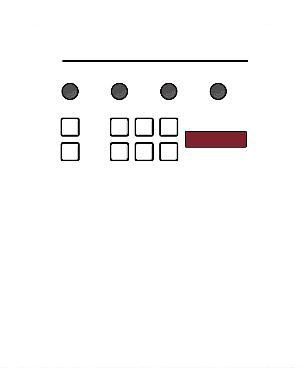
Matte
Lum Sat OpacityHue
Matte
Bkgd
Wipe
Border
Fill
Key
1
Preset
Border
Key
2
Border
Line
DSK
Figure 3-12. Matte Panel Section
BKGD 14
Delegation
3-27
Page 74

Section 3 — Controls & Menus
Pattern
The Pattern panel section (Figure 3-13) allows you to select and
adjust wipe patterns, preset pattern keys, and key masks.
Pattern
Size Width Softness Symmetry
Mask/
Preset
Invert
Mask/
Preset
Pattern
Normal
Wipe
Reverse
Border
Flip
Flop
Soft
Symm
Wipe Direction
3-28
User
1
Learn
User
Wipe
User
2
Undo
User
3
Menu
4
User
Figure 3-13. Pattern Panel Section
Pos
WIPE
Center
Page 75

Pattern Selection Buttons
The ten pattern buttons select the ten primary wipe patterns, and
the [MENU] button opens the Wipe menu, providing access to more
patterns.
■ To select one of the ten primary patterns, momentarily press
■ To select a menu pattern, press the [MENU] button to open the
User Wipe Buttons
You can store and recall pattern setups, including modifiers,
using the four User buttons and the [LEARN USER WIPE] button.
■ To store a pattern, just press [LEARN USER WIPE] followed by
Pattern
a [PATTERN] button. The button will light. Only one pattern
button can be selected at a time.
Wipe menu and use the menu controls to select a pattern from
the menu.
one of the User buttons, such as [USER 1].
■ To recall a pattern, press the User button in which it is stored.
■ If you need to undo a user wipe learn or recall, press [UNDO]
after the learn or recall before you press any other button. The
conditions prior to the learn or recall will be restored.
3-29
Page 76

Section 3 — Controls & Menus
Pattern Adjustments
Available pattern adjustment controls are described below.
Positioner (Joystick)
The positioner controls operate as follows:
■ Turning on the [POS] button enables the positioner and
returns the pattern to the position it was last moved to. You
can then use the positioner to move the pattern to any screen
position. Turning off the [POS] button disables the positioner.
■ When you press the [CENTER] button, the pattern returns to its
default center position.
Wipe Direction
The three wipe direction buttons are [NORMAL], [REVERSE], and
[FLIP FLOP]. Normal and Reverse modes cannot both be selected at
the same time. However, Flip Flop mode works in combination
with either Normal or Reverse.
3-30
■ When [NORMAL] is on, the white areas on the pattern buttons
indicate new video that will be revealed as the pattern moves.
■ When [REVERSE] is on, the black areas on the pattern buttons
indicate new video.
■ When [FLIP FLOP] is on together with one of the other buttons
(Normal or Reverse), the first wipe transition moves in the
direction indicated by the other lighted button. Then the next
transition moves in the opposite direction (flip flop). This
feature allows you to “wipe on” and “wipe off” using
whichever starting direction you choose.
Mask Preset Pattern/Wipe
The [MASK/PRESET PATTERN] and [WIPE] buttons delegate the
(WIDTH), (SOFTNESS), (SYMMETRY), and [MASK/PRESET INVERT]
controls to a mask or preset pattern key or to a wipe pattern. Only
one of the two buttons may be on at a time.
Page 77

Pattern
Size and Border Width, Softness, and Symmetry
■ Patterns can have a matte-filled border if you turn on the
[BORDER] pushbutton. When [BORDER] is on, the (WIDTH) knob
sets the width of the border. The Matte controls set the edge
color.
■ When you turn on the [SOFT] button, the (SOFTNESS) knob sets
the diffusion of the pattern edge. When the [SOFT] button is
off, the pattern has a hard edge.
■ If the [SYMM] and [SOFT] buttons are both on, the (SYMMETRY)
knob sets the balance or evenness of the softness applied to
the pattern edge. When the [SYMM] button is off, softness of the
edge is evenly balanced. When the [SOFT] button is off, the
symmetry control has no effect.
Mask/Preset Invert
When you select a mask or preset pattern, you can toggle the
[MASK/PRESET INVERT] button to change the area of the picture that
is affected by the mask or fill video. When the invert function is
off, the white area on the pattern buttons represents the area of the
screen where masking occurs or where the fill video appears.
When the invert function is on, the black area on the pattern
buttons represents the area of the screen where masking occurs or
where the fill video appears.
Wipe Menu
When you press the [MENU] button, the Wipe menu appears in the
menu display. This menu provides access to additional wipe
patterns as well as additional pattern modifiers, including aspect
ratio adjustments, sine wave modulation of the pattern, pattern
rotation, and pattern multiplication.
3-31
Page 78

Section 3 — Controls & Menus
Transition
The Transition section (Figure 3-14) allows you to select and
transition the effects background and key layers (but not the DSK)
on or off air at the Program output. You can do a cut transition or
you can use an automatic transition or the lever arm to do a mix
or wipe transition.
Transition
Bkgd
Mix
Cut
Key
1
Key On Key On
Over Over
Key
2
Wipe
Auto
Trans
Figure 3-14. Transition Controls
Trans
Preview
60
3-32
Page 79

Bkgd, Key 1, Key 2
Transition
The [BKGD], [KEY 1], and [KEY 2] pushbuttons delegate the
transition controls to the effects keyers and/or the PGM/PST
background mixer. You can select one button or push multiple
buttons simultaneously. The selected buttons light and the others
turn off automatically. The next transition affects only the lit
functions.
Bkgd
The [BKGD] button selects the background transition mode and
delegates the transition controls to the PGM/PST background
mixer. The next transition places PST bus video on air and takes
the current PGM bus video off air. Selections on the two buses
flip-flop at the end of the transition.
Key 1 and Key 2
The [KEY 1] and [KEY 2] buttons select the key transition mode and
delegate the Key bus, Keyer, Matte, and Transition controls to
Keyer 1 or Keyer 2, respectively. When you select one of these
buttons, the next effects transition takes the selected key on or off
air at the Program output. If you select both buttons, the Key bus
and Keyer delegate to Keyer 1, but both keys are affected by the
next transition.
■ The KEY ON legend lights when the keyer is on air.
■ The OVER legend lights to indicate which key layer is on top
of the other.
■ If you double-press [KEY 1] or [KEY 2], the Keyer menu appears,
allowing you to make adjustments to the key.
3-33
Page 80

Section 3 — Controls & Menus
Mix and Wipe Transition Type
The [MIX] and [WIPE] buttons determine the appearance of the next
effects automatic or lever arm transition—either a dissolve or a
pattern transition. Only one button may be selected at a time.
Mix
The [MIX] button selects a dissolve transition. Keys dissolve on or
off, and/or Preset video dissolves into and replaces Program
video.
Wipe
The [WIPE] button selects wipe transition mode and delegates the
Pattern and Matte sections to wipe adjustments. In wipe transition
mode, a moving pattern edge wipes keys on or off and/or
replaces Program bus video with Preset bus video.
■ The Pattern controls allow you to select a wipe pattern and
position its starting point. They also allow you to turn the
wipe border on or off, adjust edge or border softness, and
adjust edge or border softness symmetry.
3-34
■ The Matte controls allow adjustment of the wipe border
characteristics, including luminance, saturation, hue, and
opacity.
■ A double press of the [WIPE] Transition button brings up the
Wipe menu, giving you access to more pattern adjustments,
including more patterns, aspect, reverse, rotation, and
multiplication.
Page 81

Transition Controls: Cut, Auto Trans, and Lever Arm
The transition controls give you three ways to do an effects key or
PGM/PST transition: an instantaneous cut, an automatic
transition of a preset duration, or a manual lever arm transition.
■ The [CUT] button causes a full transition to occur instantly. The
button does not light.
■ The [AUTO TRANS] button starts an immediate transition that
extends for the period of time (in video frames) shown in the
Transition rate display. The button lights for the duration of
the transition. To set a new transition rate, press [M/E TRANS]
in the E-MEM section, enter a number using the keypad, and
press [ENTER]. The new rate appears in the Transition rate
display.
Pause feature: An automatic transition in progress pauses if
you press [AUTO TRANS] again and resumes if you press it a
third time.
■ The LEVER ARM gives you direct manual control of the
direction and speed of a transition. When you move the lever
arm off of a limit, the transition begins and exactly tracks the
lever arm motion. A green arrow lights and points in the
direction the lever must travel in order to finish the transition.
Transition
You can also use the three transition methods together:
■ If you press [CUT] during an auto transition or when the lever
arm is partly off the limit, the sources involved will instantly
swap places; that is, the source that was transitioning on will
go off and vice versa.
■ You can begin a transition with the lever arm and finish with
[AUTO TRANS], or you can begin an automatic transition and
finish with the lever arm.
3-35
Page 82
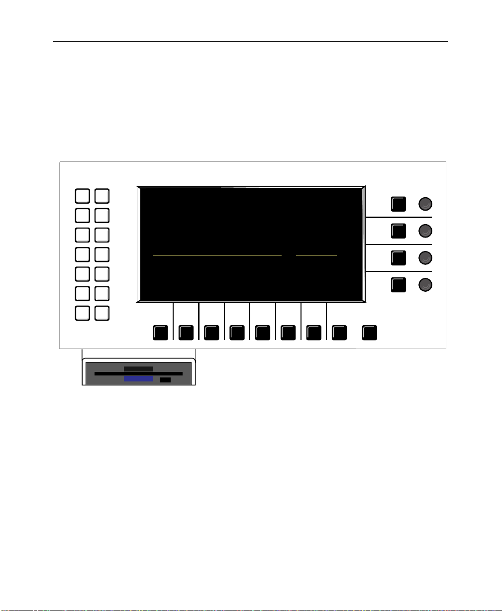
Section 3 — Controls & Menus
Visual Display and Menus
The visual display in the upper left corner of the control panel
presents system menus, and the associated pushbuttons and
knobs provide control over menu functions. Figure 3-15 shows
the display together with its pushbuttons and knobs.
Misc
Config
Chroma
Keyer
Key
Prior/
Proc
Depth
Amp
Stat
Wipe
Copy/
Swap
Disk
Last
Menu
Model
DIGITAL
200
1
Exit
3-36
Figure 3-15. Visual Display Panel Section
Page 83

Menu Pushbuttons and Knobs
The display panel includes associated pushbuttons and knobs
that work interactively with the display menus to control the
switcher operation. General operation of these menu buttons and
knobs is explained below:
■ The white menu “hot buttons” at the left of the display
activate the top level menus.
■ The black buttons and knobs surrounding the display are
“soft” buttons and knobs that change function with each
menu. Labels displayed along the bottom and right edges of
each menu indicate the functions of the soft controls. The “>”
display symbol indicates a lower level menu that you can
view when you press the associated soft button.
■ All menus - Quickly pressing a soft knob’s soft button twice
will return the value to default.
■ The [Exit] button takes you up one menu level.
Visual Display and Menus
Keypad Numeric Entry
The buttons associated with the soft knobs at the right of the menu
display enable keypad entry of soft knob values using the ten
register buttons on the E-MEM panel. This is helpful when
multiple digit numbers need to be entered.
To enter a value, press the associated soft button to highlight the
value field on the menu, enter a number using the E-MEM
keypad, and press [ENTER] on the E-MEM panel. To enter a
negative number, first press the number on the E-MEM keypad,
then the +/- button below the E-MEM keypad.
3-37
Page 84

Section 3 — Controls & Menus
Double-Press Pushbuttons
Many of the pushbuttons on the switcher panel will automatically
bring up the appropriate menu if you double press them (press
the button twice in rapid succession). Pushbuttons that have
corresponding double-press functions (called DPOPs, for “double
press opens”) are listed in Table 3-1.
Table 3-1. Double-Press Pushbuttons
DPOPs Action
• Crosspoints
• Bus Delegates Aux 1 and Aux 2
• Effects Send Key 1, Key 2, DSK
• Keyer buttons Opens Keyer Menu
• Chroma Key button Opens Chroma Key Menu
• Clear Button (E-MEM subpanel) Opens Misc Menu
• Soft Buttons on right side of
menu
Opens Proc Amp Menu
Restores soft knob to default
value
3-38
Page 85

Menus
Visual Display and Menus
The main menus corresponding to the white top level menu
buttons at the left of the display are presented in alphabetical
order on the following pages. Each main menu and its sub-menus
are described in detail. The main menus are the following:
■ Chroma Key—page 3-42
■ Configuration—page 3-54
■ Copy/Swap—page 3-75
■ Disk—page 3-80
■ Keyer—page 3-98
■ Last Menu—page 3-102
■ Miscellaneous—page 3-102
■ Priority/Depth—page 3-104
■ Proc Amp—page 3-106
■ Status—page 3-108
■ Wipe—page 3-110
See the following page for a menu tree that presents all of the main
menus and their sub-menus.
3-39
Page 86

Section 3 — Controls & Menus
Menu Tree
Figure 3-16 presents a chart of the 1200 menu system. The menus
shown on the left side of the figure are the top-level menus that
you can access by pressing the white pushbuttons on the left side
of the display. Additional lower level menus are shown branching
to the right in the figure.
TOP MENU
PUSHBUTTONS
Config
Misc
Keyer
Chroma Keyer
Priority/Depth
Proc Amp
Wipe
Copy/Swap
Status
Last Menu
Disk
CONFIG MENU
System Params
Define Inputs
Crosspoint Map
Outputs
Timing
Ports
GPI
Tally
KEYER MENU
Clip Mode
Key Memory
Opacity
Gain/Bkgd Clip
Clip/Fgd Clip
Key Border
PRIORITY/DEPTH MENU
Z-Key Mode
Joystick Z Deleg
Prior/Depth Adj
WIPE MENU
Aspect
Rotation
Clear Pattern
Center Pattern
Pattern Scan
Multiplication
Modulation
STATUS MENU
Lists S/W & H/W Versions
LAST MENU
Return to Previous Menu
4:3/16:9, Edit Field Dom, Clock
Define Inputs, Select CK Source, Xpt Legends
Map Inputs to Crosspoints
Configure Outputs
Switcher Timing Adjustment
Serial Port Configuration
GPI Input and Output Setup
Tally Output Relay Monitoring and Testing
Select Clip/Gain or Fgd/Bkgd Clip
Key Memory On/Off
Opacity Adjustment
Gain/Bkgd Clip Adjustment
Clip/Fgd Clip Adjustment
Set Border
Depth or Priority Mode
Assigns Joystick to a Key Layer
Priority, K1 Depth, K2 Depth, Softness
Aspect On/Off & Adjustment
Rotation Mode & Adjustments
Clears Pattern
Center Pattern Adjustment
Odd, Even, or Interlaced
H & V Multi On/Off, Set No. of Multiples
H & V Modulation On/Off & Adjustments
3-40
Page 87
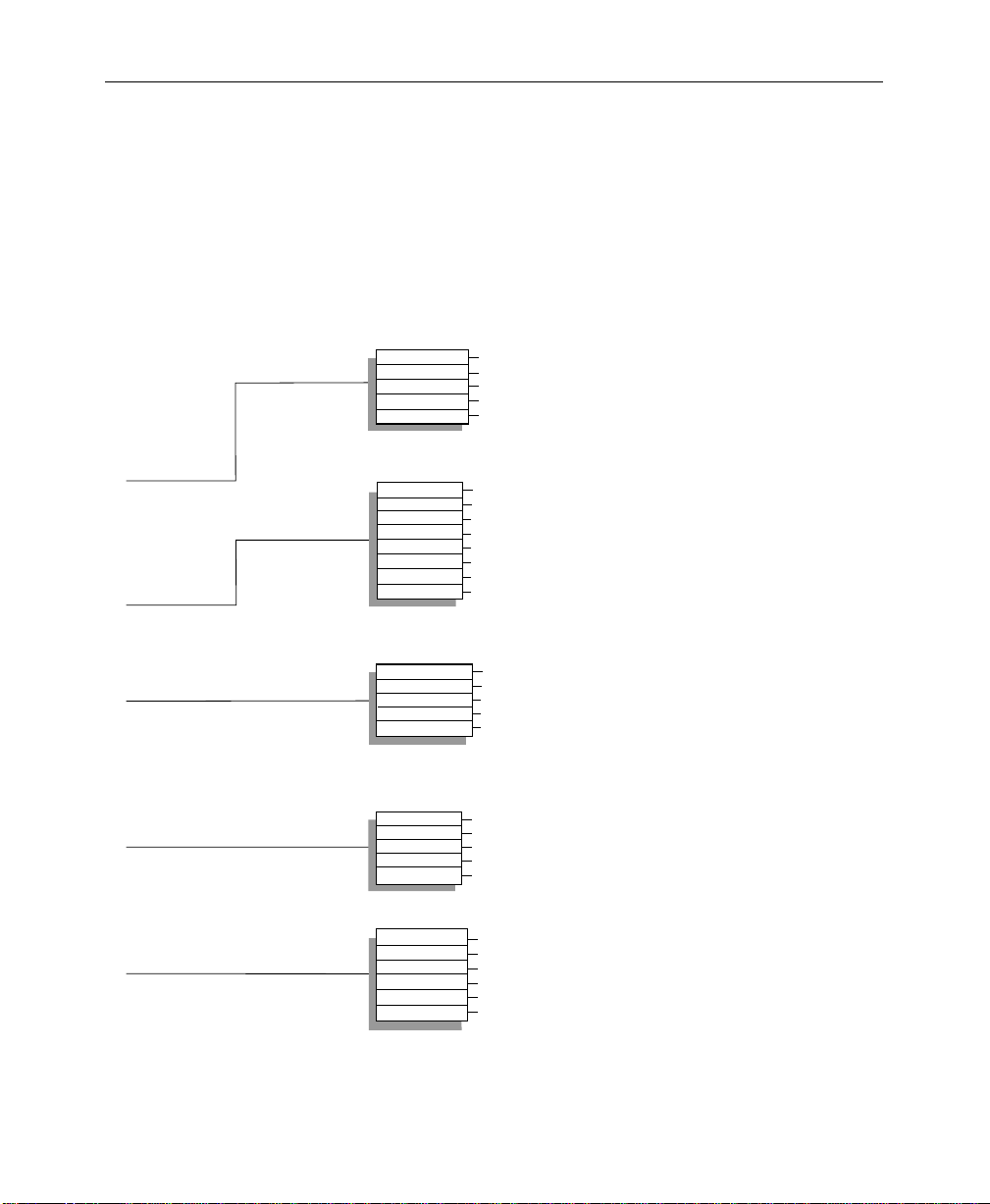
Visual Display and Menus
MISC MENU
Clear Work Buffer
Clear DP RAM
Factory Reset
LampSaver Delay
Shut Down
CHROMA KEY MENU
Auto Setup
Show Key
Suppress Level
Fgnd Suppress
Key Edge
Shadow Proc
Force Mask
Recall Default
Clears button and knob settings
Clears working buffer and E-MEMs
Clears working buffer, E-MEMs, configurations
Sets LampSaver Delay Time
Allows Safe Power Down
Enables Auto Setup of Chroma Key
Shows Key Filled with White
Delegates Soft Knobs to Chroma or Luma Suppress
Foreground Suppression Adjustments
4:2:2/4:4:4, Edge Processing, Add/Mult
Shadow Proc On/Off, Opacity, Gain, Clip
Enable and Adjust Fgnd/Bkgd Mask
Recalls default chroma keyer settings
PROC AMP MENU
Clear Proc Amp
Clear All Prc Amps
Proc Amp Enable
Xpt Select
Proc Adjustments
COPY/SWAP PROC AMP MENU
Copy Keyer
Copy Matte
Copy Border
XPT
Do Copy/Swap
Copy or Swap Keyer settings
Copy or Swap Matte settings
Copy or Swap Border settings
Copy or Swap Crosspoint settings
Do Copy or Swap
Clears Selected Proc Amp to Default Values
Clears All Proc Amps to Default Values
Turns Proc Amps On or Off
Selects Xpt Column to be Adjusted
Luma Gain & Offset, Chroma Sat, Hue, U & V Offset
DISK MENU
List Directory
Change Directory
Save
Load
Utility
Format
List Files in a Directory on a Disk
Change to Another Directory on a Disk
Save E-MEM or Config File to Disk
Load E-MEM or Config File from Disk
Delete or Lock Files, Make Directories
Format a Disk
Figure 3-16. Display Menu Tree
3-41
Page 88

Section 3 — Controls & Menus
Chroma Key Menus
Press the [Chroma Key] top menu button to display the Chroma
Key top-level menu shown in Figure 3-17. This menu provides
control of chroma keys for any of the switcher’s three keyers.
Chroma Key Menu Functions:
[AUTO SETUP]—Turns on chroma key Auto Setup mode. This
mode automatically creates a chroma key when you select the
chroma key background color. To select this color, position the
monitor cursor over the desired color in the background scene
and press the button on the top of the joystick.
[SHOW KEY]—Enables or disables Show Key mode. When on, this
mode fills the chroma key foreground with a white matte over a
black matte background. This makes edges and foreground
transparency more visible for fine adjustment.
[SUPPRESS LEVEL]—Selects background chroma or luma for
suppression level adjustment.
3-42
(BACKGROUND LUMA SUPPRESS LEVEL)—Adjusts the level of
luminance suppression applied to the chroma key
background scene.
(BACKGROUND CHROMA SUPPRESS LEVEL)—Adjusts the level
of chroma suppression applied to the chroma key
background scene. Chroma suppression cancels out
unwanted color in the background. Normally this control
should be set at about 50%.
[FGND SUPPR>]—Displays the Foreground Suppress menu.
[KEY EDGE>]—Displays the Key Edge menu.
[SHADOW PROC>]—Displays the Shadow Proc menu.
[FORCE MASK>]—Displays the Force Mask menu.
Page 89

Chroma Key Menus
[RECALL DEFAULT>]—Restores the chroma keyer to its default
settings.
(BACKGROUND HUE ANGLE)—Selects the color in the chroma key
background scene that will be suppressed by the background
suppression feature.
(SELECTIVITY)—Narrows or widens the range of hues captured by
the chroma key hue adjustment.
CHROMA KEY MENU
ON
CHROMA
OFF
AUTO
SETUP>
SHOW
KEY
SUPPRESS
R
M
Y
B
G
C
LUMA
SHADOW
LEVEL
FGND
SUPPR >
KEY
EDGE >
PROC >
Figure 3-17. Chroma Key Top Menu
BACKGROUND
= 351 degrees
SELECTIVITY
BACKGROUND LUMA
SUPPRESS LEVEL
FORCE
MASK >
RECALL
DEFAULT
HUE ANGLE
= 34%
= 20%
Exit
3-43
Page 90

Section 3 — Controls & Menus
Chroma Key Auto Setup Menu
From the Chroma Key top menu, press [AUTO SETUP] to display
the Chroma Key Auto Setup menu shown in Figure 3-18.
Auto Setup Menu Functions:
[TAKE]—Selects the desired chroma key background color when
the Auto Setup cursor on the Program monitor has been placed
over the desired color using the joystick. The [TAKE] button serves
the same function as the button on the top of the joystick when
Auto Setup mode is on.
[CANCEL]—Cancels Auto Setup mode.
3-44
Page 91

CHROMA KEY MENU
Use joystick to move monitor cursor over desired hue.
To select the hue, press the button on the joystick,
To cancel Auto Setup, press the CANCEL button below,
Chroma Key Menus
AUTO SETUP:
or press the TAKE button below.
or press the EXIT button.
TAKE
CANCEL
Exit
Figure 3-18. Chroma Key Auto Setup Menu
3-45
Page 92

Section 3 — Controls & Menus
Chroma Key Fgd Suppress Menu
From the Chroma Key top menu, press [FGD SUPPRESS>] to
display the Chroma Key Foreground Suppress menu shown in
Figure 3-19. This menu includes adjustments to suppress
(remove) background color and noise that appears in the
foreground.
Foreground Suppress Menu Functions:
[FG NOISE SUPPRESS]—Sets the level of foreground noise
suppression to off, low, medium, or high. This removes noise
from the low chroma portions of the foreground video.
[FG COLOR SUPPRESS]—Turns foreground color suppression ON or
OFF. When ON, foreground suppression removes background
color that spills onto the foreground video. This unwanted color
may be the same as the background color (typically, blue or
green), or it may mix with a foreground color. For example, blue
spill may mix with red in the foreground, distorting the red to
magenta. Foreground color suppression allows you to suppress
this distortion, restoring the original foreground color.
3-46
[HUE ANGLE]—Delegates foreground suppression color detection
soft knobs as explained below. Two separate colors can be
independently detected and suppressed.
(FOREGROUND HUE SELECT ANGLE)—This soft knob appears
when [HUE ANGLE] is set to SELECT. It selects the hue in the
foreground that will be removed by the suppression circuitry.
This is useful for removing background color that spills onto
the foreground.
(SELECTIVITY)—Narrows or widens the range of hues selected
by the Foreground Hue Angle adjustments.
(FOREGROUND HUE SUPPRESS ANGLE)—This soft knob appears
when [HUE ANGLE] is set to SUPPRESS. When you adjust this
soft knob, you are selecting a second color to be suppressed in
the foreground. This is useful for removing variations of the
background color that occur when the background color
mixes with foreground colors.
Page 93

Chroma Key Menus
[SUPPRESS LEVEL]—Selects foreground chroma or luminance
suppression level adjustment.
(FOREGROUND LUMA SUPPRESS LEVEL)—Appears when
[SUPPRESS LEVEL] is set to LUMA. Adjusts the level of
luminance suppression applied to the foreground video.
(FOREGROUND CHROMA SUPPRESS LEVEL)—Appears when
[SUPPRESS LEVEL] is set to CHROMA. Adjusts the level of
chroma suppression applied to the foreground video.
Normally this control should be set at about 100%.
(FRINGE CONTROL)—Controls the color of the foreground video in
the fringe areas. Sometimes the fringe area is affected by the
background color in such a way that the color in the fringe area is
lost. The Fringe control allows you to add color back into the
fringe area.
CHROMA KEY FGD SUPPRESS
Y
HIGH
MEDIUM
LOW
OFF
FG NOISE
SUPPRESS
ON
OFF
FG COLOR
SUPPRESS
SUPPRESS
SELECT
HUE
ANGLE
CHROMA
LUMA
SUPPRESS
LEVEL
Figure 3-19. Chroma Key Foreground Suppress Menu
R
M
B
G
C
FGND HUE
SELECT ANGLE
= 53 DEGREES
SELECTIVITY
= 54%
FGND LUMA
SUPPRESS LEVEL
FRINGE CONTROL
= 30%
= 7%
Exit
3-47
Page 94

Section 3 — Controls & Menus
Chroma Key Edge Menu
From the Chroma Key top menu, press [KEY EDGE>] to display the
Chroma Key Edge menu shown in Figure 3-20.
Chroma Key Edge Menu Functions:
[KEY SOURCE]—Selects a 4:2:2 resolution chroma key signal from
the KEY bus or a 4:4:4 dual link source, such as a telecine output.
[V EDGE PROC]—When ON, this feature enables vertical processing
of the chroma key and adds a frame of delay to the chroma key
path. This allows you to adjust the size of the key along the top
and bottom edges. The TEMPORAL selection averages two frames
together to reduce noise in the edge. When OFF, all vertical edge
processing is turned off, including the frame of delay. Note that
the frame of delay may cause problems for some applications,
such as recording on a VTR in write-after-read mode; turn edge
processing OFF to turn off the delay.
[KEY SIZE]—Enables adjustment of horizontal and/or vertical key
size using the (KEY SIZE) soft knob. [V EDGE PROC] must also be ON
to allow vertical key sizing. When OFF, key size is unity.
3-48
(KEY SIZE)—Adjusts size of the key in the horizontal and/or
vertical dimension when enabled by the [KEY SIZE] button.
[KEY SOFTNESS]—Enables softness adjustment of the horizontal
and vertical key edges. When OFF, H and V softness are zero.
(KEY SOFTNESS)—Adjusts horizontal or vertical key edge
softness when enabled by the [KEY SOFTNESS] button.
[KEY POSITION]—Enables adjustment of the key position.
(KEY POSITION)—Adjusts horizontal or vertical key position
when enabled by the [KEY POSITION] button.
Page 95

Chroma Key Menus
[EDGE CONTROL]—Selects a multiplicative or additive (mattestyle) chroma key. Multiplicative works best when the key edges
are soft, such as when smoke or fog is present in the foreground.
Additive works best when you are striving to preserve as much
realistic detail in the key edges as possible.
CHROMA KEY EDGE MENU
CHROMA KEYER HAS ONE FRAME OF DELAY
BOTH
VERT
HORIZ
OFF
KEY
SIZE
4:4:4
4:2:2
KEY
SOURCE
TEMPORAL
ON
OFF
V EDGE
PROC
Figure 3-20. Chroma Key Edge Menu
BOTH
VERT
HORIZ
OFF
KEY
SOFTNESS
VERT
HORIZ
OFF
KEY
POSITION
MULT
ADD
EDGE
CONTROL
KEY SIZE
= 0% H
= 0% V
KEY SOFTNESS
= 0% H
= 0% V
KEY POSITION
= 0% H
= 0% V
Exit
3-49
Page 96

Section 3 — Controls & Menus
Chroma Key Shadow Proc Menu
From the Chroma Key top menu, press [SHADOW PROC>] to
display the Chroma Key Shadow Proc menu shown in
Figure 3-21. This menu allows you to adjust chroma key shadows.
Shadow Proc Menu Functions:
[SHADOW PROC]—Turns shadow processing ON or OFF. When
shadow processing is on, the following shadow adjustments are
available:
(SHADOW CLIP)—Sets the threshold level above which the
shadow image becomes visible.
(SHADOW GAIN)—Sets shadow density.
(SHADOW OPACITY)—Interacts with the Shadow Gain control to
remove noise from the shadow and adjust shadow density.
3-50
Page 97
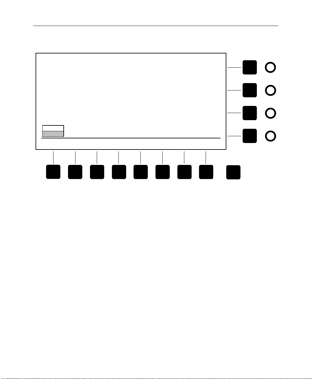
Chroma Key Menus
CHROMA KEY SHADOW PROC MENU
ON
OFF
SHADOW
PROC
Figure 3-21. Chroma Key Shadow Proc Menu
SHADOW OPACITY
=30%
SHADOW GAIN
= 42%
SHADOW CLIP
= 67%
Exit
3-51
Page 98

Section 3 — Controls & Menus
Chroma Key Force Mask Menu
From the Chroma Key top menu, press [FORCE MASK>] to display
the Chroma Key Force Mask menu shown in Figure 3-22. This
menu controls the chroma key box mask, allowing you to apply it
to the background or foreground suppression to turn off the key
in selected areas.
Force Mask Menu Functions:
[BKGD MASK]—Turns background suppression mask ON or OFF.
When ON, the mask forces the key off, preventing keying in the
masked areas. For example, if a person in the chroma key scene
has blue eyes (assuming a blue keying color), his or her eyes will
need to be masked to prevent them from keying.
[FGND MASK]—Turns foreground suppression mask ON or OFF.
When ON, this function prevents foreground suppression in the
masked areas of the foreground. For example, a foreground object
may be the same color as the color you are trying to suppress in
another part of the foreground. You can prevent suppression of
the object using the mask.
3-52
[INVERT MASK]—Inverts the mask. Normally, the area inside the
mask box is masked. When invert is ON, the area outside the mask
box is masked.
[JOYSTICK]—Turns joystick positioning of the mask ON or OFF.
(SIZE)—Adjusts size of the mask shape.
(ASPECT)—Adjusts aspect ratio of the mask box.
(SOFTNESS)—Adjusts softness of the mask edges.
Page 99
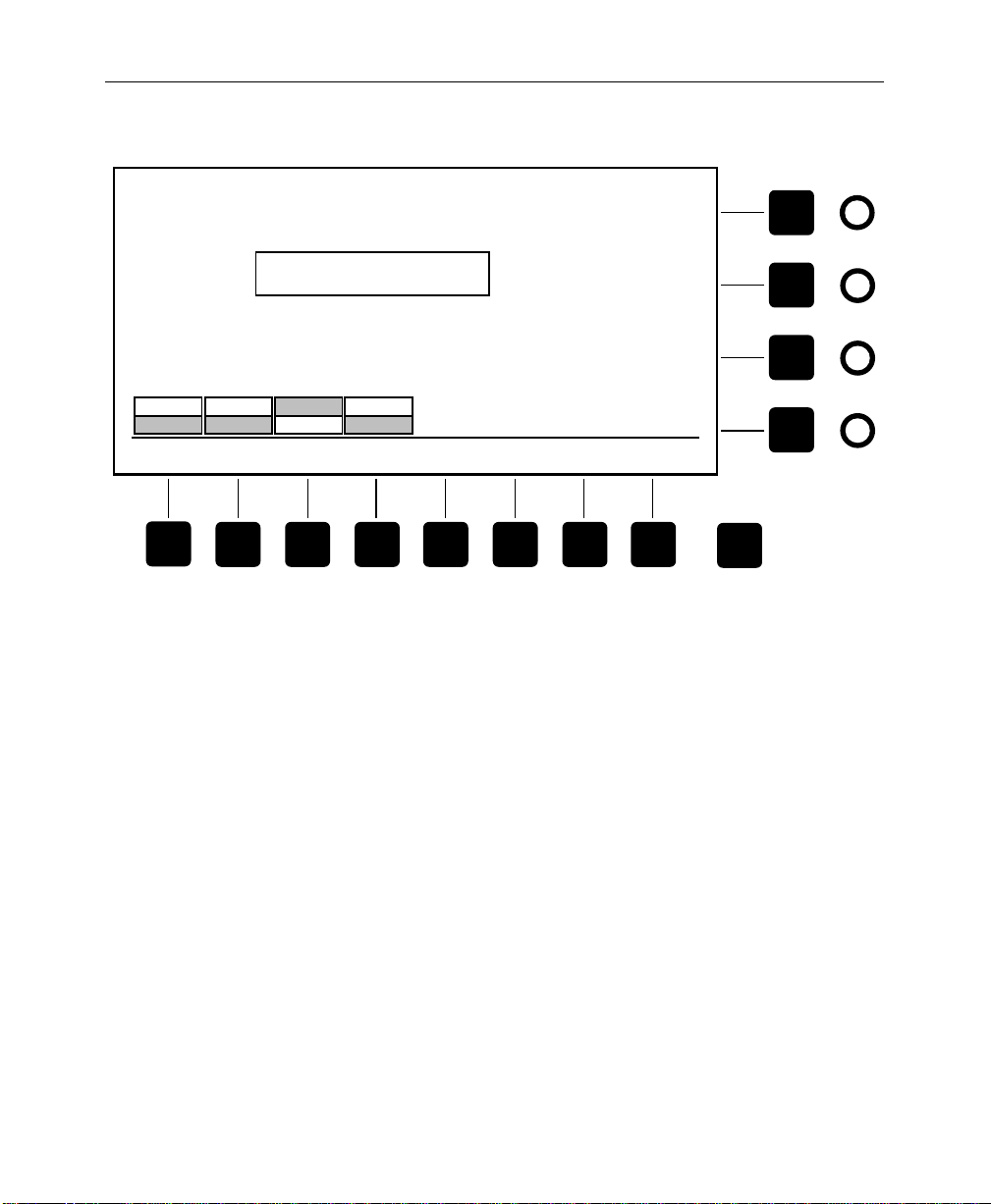
Chroma Key Menus
CHROMA KEY FORCE MASK MENU
Joystick is in use. To release it,
select RELEASE below or exit menu
ON
OFF
BKGD
MASK
ON
OFF
FGND
MASK
INVERT
NORMAL
INVERT
MASK
USE
RELEASE
JOYSTICK
Figure 3-22. Chroma Key Force Mask Menu
SIZE
= 25%
ASPECT
= 0.0
SOFTNESS
= 10%
Exit
3-53
Page 100

Section 3 — Controls & Menus
Configuration Menus
Press the white [Config] top menu button to display the
Configuration top menu shown in Figure 3-23. This menu lets you
configure your system to suit your particular requirements.
Configuration Menu Functions:
[SYSTEM PARAMS>]—Displays the System Parameters menu.
[DEFINE INPUTS>]—Displays the Define Inputs menu.
[XPT MAP>]—Displays the Crosspoint Map menu.
[OUTPUTS>]—Displays the Outputs menu.
[TIMING>]—Displays the Timing menu.
[PORTS>]—Displays the Port Configuration menu.
[GPI>]—Displays the GPI Inputs menu.
3-54
[TALLY>]—Displays the Tally menu.
 Loading...