

Page 1
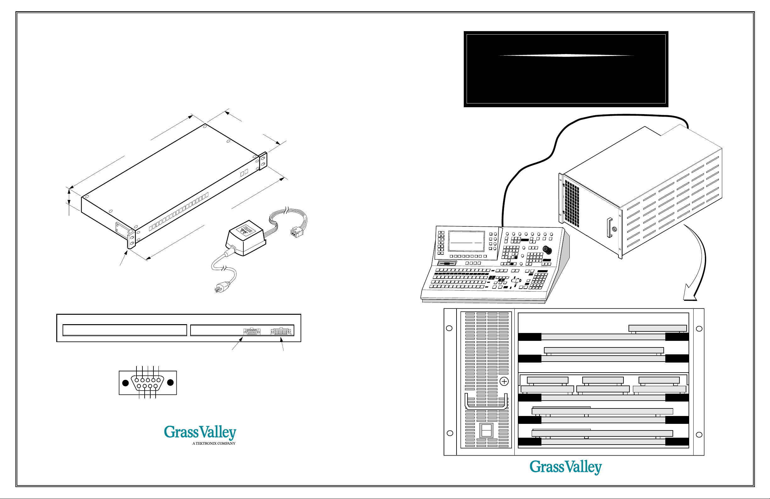
Satellite Auxiliary Control Panel Option
The Satellite Auxiliary Bus Panel provides remote control of the switcher’s auxiliary buses. It connects to
the switcher electronics frame via a serial control cable connected to a frame serial port. Power is supplied
by an external transformer which can be switched between 120 and 230 volts ac.
7.50"
(19.0CM)
17.00"
(43.2CM)
Model 1200
Digital Production Switcher
Installation Planning Guide
Signal Processor Frame
19.00"
1.72"
(48.3CM)
(4.4CM)
DC connector
Power Supply Transformer
Removable Rack Ears
May be repositioned or removed
120 or 230 Vac selectable,
50–60 Hz, 10 Watts
for flush mounting in a console
AC Connector
4 GND
5 GND
2 RX -
3 TX +
1 GND
J2-Serial Control
Port (male 9-pin D)
J1-DC Power input
12–22 Vdc
Port fixed at RS-422,
9600 baud, 8 bits,
1 stop bit, no parity.
6 GND
8 TX -
9 GND
7 RX +
NORTH AMERICA Grass Valley, CA (916) 478-3000 SOUTH AMERICA Miami, FL (305) 477-5488 EUROPE Marlo, UK (01628) 403699 ASIA Hong Kong (852) 5987118 JAPAN Tokoyo, (03) 5992-0621
8327C03B (TP0717-00B)
©1994 The Grass Valley Group, Inc. A Tektronix Company. Grass Valley is a registered trademark of Grass Valley Group, Inc
The information in this publication is furnished for informational use only, is subject to change without notice, and should not be
construed as a commitment by The Grass Valley Group, Inc. The Grass Valley Group, Inc. assumes no responsibility or liability
for any errors or inaccuracies that may appear in this publication.
Control Panel
Model
DIGITAL
200
1
1
0
Power Supply
Frame Module and Submodule Locations
064909 Borderline
064908 Key 1 Processor
064815/912 DAC Option
064815/912 DAC Option
064910 Preview Mixer Option Module
064914 SPG Submodule
064911 Control Processor Module
064925 Chroma Keyer Submodule
064905 Crosspoint Module
064909 Borderline 064909 Borderline
064908 Key 2 Processor 064908 DSK Processor
064907 Keyer Module
064913 Depth Option
064910 Program Mixer Module
064913 Depth Option
Page 2
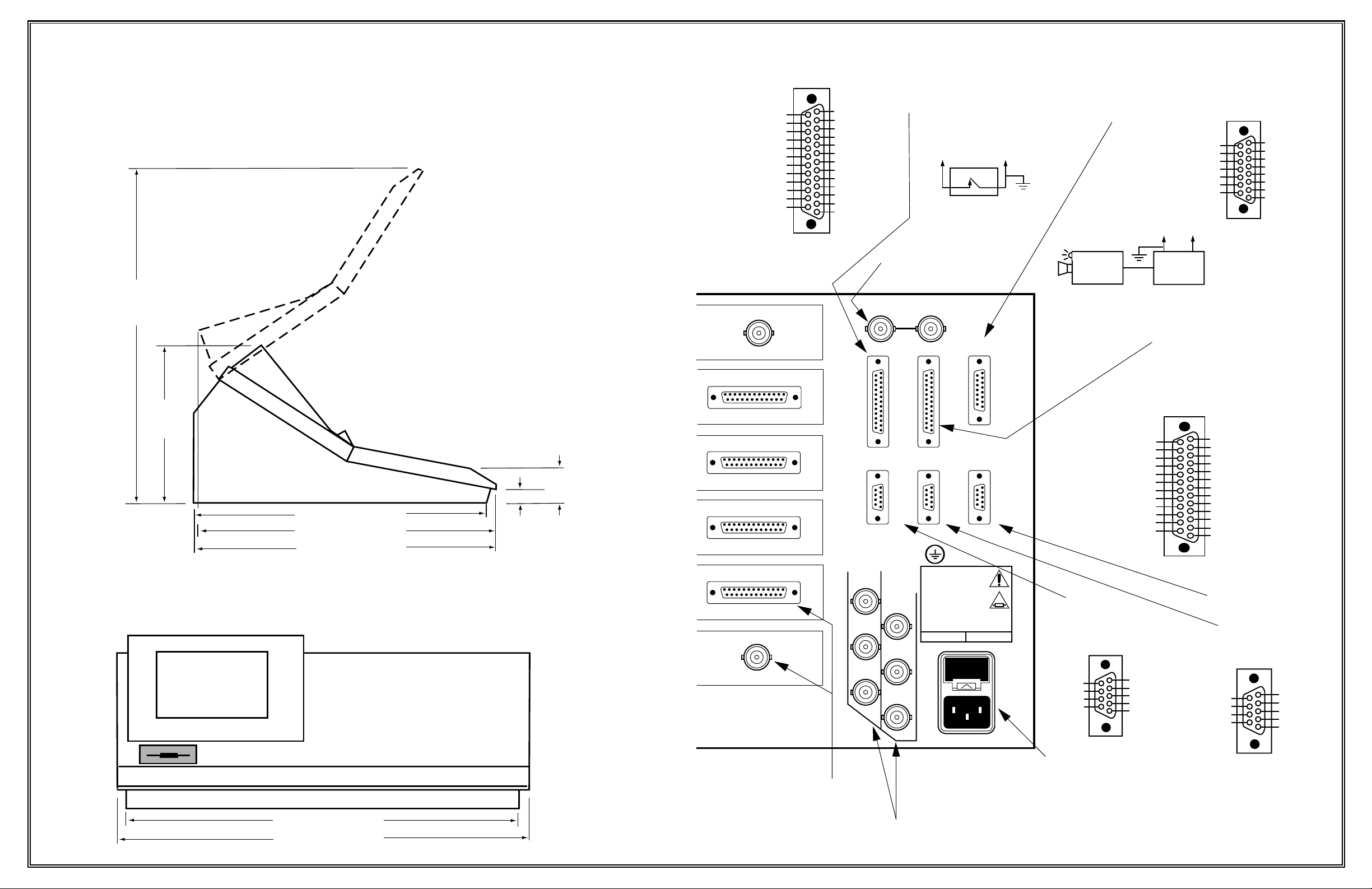
Control Panel Installation
The control panel consists of a single unit which you can place on a desktop or flush mount in a console. Be sure to leave room behind the panel for making cable connections and above the panel for
opening the lid.
23.28 in.
(591 mm)
25 NC
24 NC
23 NC
22 NC
21 NC
(COM)—20 GPI OUT0 A1
19 GPI OUT1 A1
18 GPI OUT2 A1
17 GPI OUT3 A1
16 GPI OUT4 A1
15 GPI OUT5 A1
14 GPI OUT6 A1
PUT MODULE
GPI J27 Female 25-pin D
13 GPI OUT7 A1
12 GPI OUT8 A1
11 GND
10 GND
9 GPI IN8 A1
8 GPI IN7 A1
7 GPI IN6 A1
6 GPI IN5 A1
5 GPI IN4 A1
4 GPI IN3 A1
3 GPI IN2 A1
2 GPI IN1 A1
1 GPI IN0 A1(COM)
General Purpose I/FConnector
8 Inputs trigger switcher functions
8 Outputs trigger external devices
To
J27 pin 9
GPI IN 8 A1
GPI Input Connection Example
Editor relay closes and triggers
External Reference
Analog Color Black
NTSC or PAL
Video Input
EXT. REF. INPUT
(LOOPING)
GPI IN0 A1 (COM)
Editor Relay
switcher GPI input
To
J27 pin 1
•
Panel-to-Frame
Connection
Tally Lamp
Camera Head
Tally and GPI Output Connection Example
Switcher functions trigger tally/GPI relay
closures, which in turn can trigger
events in external devices.
15 +14V Sense +
14 Transmit 13 Transmit +
12 Data Common
11 Data Common
10 Receive +
To
J28 pin 25
TALLY 0
(COM)
•
Camera
Control
Control Panel J29 Female 15-pin D
9 Receive -
To
J28 pin 5
TALLY 16
Tally InGND
Unit
8 NC
7 +14V Sense -
6 Panel +9V
5 Lamp +14V
4 Lamp +14V
3 NC
2 NC
1 No Connection (NC)
10.66 in.
(271 mm)
Display
16.57 in. (421 mm)
17.36 in. (441 mm)
17.42 in. (443 mm)
Desktop Mount
Note: Leave 6 inches (152 mm)
of space behind the panel for
cable connections.
Side View
0.83 in.
(21 mm)
Front View
Splash Panel
2.23 in.
(57 mm)
INPUT 4 J4
PUT MODULE
INPUT 8 J8
PUT MODULE
INPUT 12 J12
PUT MODULE
INPUT 16 J16
PUT MODULE
PGM KEY OUT 1 J20
PUT MODULE
PGM KEY OUT 2 J24
J25 J26
CONTROL
GPI TTY/TALLY
J28J27
MODEM DPM EDITOR
J31J30 J32
ANALOG
OUTPUTS
PGM
Y
PVW
Y
J33
U
U
J34
V
V
J35
GRASS VALLEY GROUP
MODEL 1000
VOLTAGE: 100–240VAC ~
CURRENT: 4A
FREQUENCY: 50–60HZ
CAUTION–RISK OF FIRE
REPLACE FUSE AS MARKED
100V–240V 5A F 250V
J36
J37
J38
5A FUSE
& SPARE
PANEL
J29
J39
TTY/Tally J28 Female 25-pin D
(COM)—25 TALLY 0
24 TALLY 1
23 TALLY 2
22 TALLY 3
21 TALLY 4
20 GND
19 TALLY 6
18 TALLY 5
17 TALLY 8
16 TALLY 7
15 TALLY 10
14 TALLY 9
Modem
Serial I/O Port
accepts a modem for
remote service by GVG
Modem J30 Female 9-pin D
RS232 / RS422
9 RI / GND
8 CTS / RX 7 RTS / TX +
6 DSR / GND
Terminal and
Tally Connector
Provides one tally for
each input. Also accepts
a VT-100 compatible
terminal or pc
13 TALLY 12
12 TALLY 11
11 TALLY 14
10 TALLY 13
9 GND
8 TALLY 15
7 GND
6 GND
5 TALLY 16
4 GND
3 TERM RX1 A1
2 TERM TX1 A1
1 GND
Editor Serial I/O Port
Digital Picture
Manipulator
Serial I/O Port
RS232 / RS422
5 GND / GND
4 DTR / GND
3 RX / RX +
2 TX / TX 1 DCD / GND
DPM J31 & Editor J32 Female 9-pin D
RS232 / RS422
9 NC / GND
8 NC / RX -
7 NC / TX +
6 NC / GND
RS232 / RS422
5 GND / GND
4 NC / GND
3 RX / RX+
2 TX / TX -
1 NC / GND
Lower Panel Surface
Tub
27.71 in. (704 mm)
29.00 in. (737 mm)
Program Luminance Key
Component Digital Outputs
Program and Preview Analog
Component Video Outputs
(Betacam, SMPTE, or EBU-N10)
AC Power Input
100-240 Vac, 50–60 Hz
.99 Power Factor Correction
400 Watts Maximum
Page 3

System Connections
20.22 in.
(514 mm)
Parallel Component Digital Video Input/Output
2 GND
3 D9
4 D8
5 D7
6 D6
7 D5
8 D4
12 D0
13 GND
24 /D1
25 /D0
10 D2
11 D1
23 /D2
9 D3
22 /D3
21 /D4
20 /D5
19 /D6
18 /D7
16 /D9
17 /D8
1 CLK
14 /CLK
15 GND
Serial and Parallel Component Digital Inputs 1-16
CCIR601 4:2:2 525 or 625 lines
PARALLEL INPUT MODULE
SERIAL IN
I
INPUT 1 J1 INPUT 2 J2 INPUT 3 J3
N
PARALLEL INPARALLEL INPUT MODULE
P
INPUT 5 J5 INPUT 6 J6 INPUT 7 J7
PARALLEL INPUT MODULE
INPUT 9 J9 INPUT 10 J10 INPUT 11 J11
PARALLEL INPUT MODULE
U
T
PARALLEL IN
PARALLEL IN
S
INPUT 13 J13 INPUT 14 J14 INPUT 15 J15
PARALLEL OUTPUT MODULE
O
PARALLEL OUT
U
T
AUX OUT 1 J17 AUX OUT 2 J18 PGM OUT 1 J19
SERIAL OUTPUT MODULE
P
U
SERIAL OUT
T
S
CLEAN FEED J21 PVW OUT J22 PGM OUT 2 J23
6.05 in.
(154 mm)
5.31 in.
(135 mm)
Important: Install the mounting
brackets on the rear of the
panel using four #6-32
screws. Secure the brackets
to the desk using four #6
wood screws. The mounting
flange at the front is not
capable of supporting
the entire panel.
Side View
15.40 in. (391 mm)
18.42 in. (468 mm)
19.58 in. (497 mm)
Console Mount
Wood screws, 10 places,
size #6 (customer supplied)
1.00 in.
(25 mm)
1.02 in.
(26 mm)
Panel
mounting flange
27.80 in. (706 mm)
Console Cutout
Clean Feed Video
(Program without DSK)
Component Digital Output
Aux Bus 1 and 2
and Effects Send
Component Digital Outputs
Preview Video
Component Digital Output
Program Video
Component Digital
Outputs
17.46 in.
(443 mm)
Page 4

Signal Processor Frame Installation
The Signal Processor Frame mounts in a standard 19-inch wide equipment rack and requires 6 rack units
of vertical space. Front and rear support are required. Leave some open space at the front of the frame for
module removal, at the back of the frame for cabling, and at the sides for cooling air flow.
Character
Generator
Typical System
Still Store
TYPICAL VIDEO SOURCES
Component Digital
Video Tape
Recorder (VTR)
Analog
Video Tape
Recorder (VTR)
Camera
WARNING
The frame is heavy. Use a mechanical
lifting device to lift it into position.
COOL AIR INTAKE
Allow space on sides
for air flow
RACK-UNITS
COOL AIR INTAKE
FRONT CLEARANCE
36" (914 mm)
6
10.5 in.
267 mm
19.00 in.
(483 mm)
24.8 in. (630 mm)
Standard 19" Rack
REAR CLEARANCE 18" (457 mm)
REAR SUPPORT BRACKET
Attach to rack rail and insert
17.25 in.
(438 mm)
12.87 in.
(327 mm)
rear support plate.
REAR SUPPORT PLATE
Move as needed to fit into
rear bracket. Rear support
EXHAUST AIR
is required.
Allow space on
sides for air flow
TP0626-06
Analog
Key Out
A to D
Analog
Video Out
A to D
EXT. REF. INPUT
(LOOPING)
EXT REF IN
Component
Digital Video
Out
Primary Inputs
Component
Digital Key
Out
Effects Send Return Path
MODEL 1200
200
Model
1
DIGITAL
CH. 1 In
CH. 2 In
Aux 1
or
Send
Key
SWITCHER
Component
Digital Video
Out
Aux 2
or
Send
Video
Clean Feed Out
Key Out
Periph Port
Null Modem Cable
(054714-03)
DPM
Port
Analog
Video Out
A to D
DPM-700
DIGITAL PICTURE
MANIPULATOR
Analog Program Out
Digital Program Out
Program Key Out
Clean Feed Out
Analog PVW Out
Analog
Video Out
A to D
Program
Monitor
Digital
Record VTR
Preview
Monitor
External Reference
Analog Color Black
Keyboard
 Loading...