

Grasso RC6, RCU6 Installation And Maintenance Manual
RC(U)6
Installation and Maintenance Manual
00.89.238 v004.00.02.en

Refrigeration Division
Grasso
All rights reserved. No part of this publication may be copied or published by means of printing,
photocopying, microfilm or otherwise without prior written consent of Grasso. This restriction
also applies to the corresponding drawings and diagrams.
For extra information as to adjustments, maintenance and repair, contact the Technical
Departmentof your supplier.
This publication has been written with great care. However, Grasso cannot be held responsible,
neither for any errors occurring in this publication nor for their consequences.
Installation and Maintenance Manual RC(U)6 v001.99.01.en

1. Document Information
• This ’lnstallation and Maintenance manual’ will
be supplied together with the compressor.
• This manual is suitable for both end-user and
contractor and will provide information on how
to transport, install, start-up and maintain the
compressor (package). It also contains a number
of "Engineering Data Sheets" and the current
"Parts List".
2. Additional Documentation
In addition to the above the following is available
for this series compressor:
• Engineering Data Sheets Book;
This book contains all engineering data for this
series compressor and the corresponding
recommended accessories. It is meant to be a
guide to the selection of these components.
• Parts book;
This book contains all current parts of the
compressor and accessories together with the
design changes applicable to earlier supplied
components ("History").
• Mounting and Installation Instructions for
Accessories;
If compressor is supplied with accessories, all the
relevant mounting and installation instructions
and spare parts information for those
accessories will be supplied together with the
compressor.
Refrigeration Division
Grasso
PREFACE
v001.99.01.en Installation and Maintenance Manual RC(U)6 V

Refrigeration Division
Grasso
PREFACE
VI Installation and Maintenance Manual RC(U)6 v001.99.01.en

This manual must be carefully read and
understood prior to installing the
compressor (package)
Installer-oriented information
The compressor (package) is filled with nitrogen to
prevent penetration of moisture. Therefore, keep
the compressor closed until the compressor
(package) is being installed. The compressor is not
filled with oil. How to charge the compressor
package with oil is discussed in Section A, §A2.3,
"Initial oil charge".
After the succesful initial run of the compressor
(package) the warranty chart must be filled in and
returned to Grasso. A warranty chart is attached
to each compressor.
Safety
This manual is written with great care, but the
contractor/installer is held responsible to examine
this information and to care of possible additional
and/ or deviated safety measures.
Safety instructions
It is the task of the contractor/installer to inform
and explain his client about the operation of the
compressor (Package).
Do respect all federal, state or local safety
regulations/legislations during installing,
connecting and operating this compressor
(package).
Typographic signs:
Indicates a caution, note or procedure to
which you should pay special attention.
Read it carefully!
Values Between [ ]
Values between [ ] are read-outs of Grasso’s
electronic control device Monitron.
Refrigeration Division
Grasso
GENERAL SAFETY INSTRUCTIONS
v001.99.01.en Installation and Maintenance Manual RC(U)6 VII

Refrigeration Division
Grasso
GENERAL SAFETY INSTRUCTIONS
VIII Installation and Maintenance Manual RC(U)6 v001.99.01.en

General information
Refrigeration Division
Grasso
Subject Feature refer to chapter:
Oil viscosity
≥ 10 cSt during operation at location of bearings
Direction of rotation of compressor drive shaft Counterclockwise when facing shaft end A2.6
Operating limits and switch settings
(for values between [ ] brackets refer to the Instruction Manual of the Monitron)
Timers Time interval refer to chapter:
Switching frequency max. 6 starts per hour A2.10.1
Time interval between stopping and re-starting min. 2 minutes A2.10.2
Time interval between starting and re-starting min. 10 minutes A2.10.2
Time interval between unloading and loading min. 3 minutes B1.2
Oil system limits Value
Oil level 25 - 75% crankcase sight glass B4
Min. oil temperature
warmer than surroundings and ≥ 20 °C (68 °F)
for NH
3 and ≥ 30 °C (86 °F) for halocarbons
A2.8
Max. oil temperature [max. Toil] see oil selection table in the appendix section B1.2
Lubricating oil pressure difference [min dOil] between 1.5 and 2.5 bar
Setting approx. 1.8 bar
A2.5.2
Temperature and pressure limits Value
Max. discharge temperature [max Tdis] 155 °C (311 °F) B1.2
Pdischarge - Psuction
< 24.0 bar
Superheat [dTo]
≥ 5 K
Cooling water inlet temperature of cylinder
head cooling system
≥Tcond + 10 K
Pressure safety limits A2.5.2
GENERAL INFORMATION AND SURVEY
OF SETTINGS AND LIMITS
v001.99.01.en Installation and Maintenance Manual RC(U)6 IX

Refrigeration Division
Grasso
GENERAL INFORMATION AND SURVEY
OF SETTINGS AND LIMITS
X Installation and Maintenance Manual RC(U)6 v001.99.01.en

SUBJECT Page no.:
PREFACE ............................................................................................................................... V
GENERAL SAFETY INSTRUCTIONS ................................................................................................. VII
GENERAL INFORMATION AND SURVEY OF SETTINGS AND LIMITS .......................................... IX
SECTION A: INSTALLATION AND PREPARATIONS FOR USE ....................................................... A1.1
A1 INSTALLATION .......................................................................................................................... A1.1
A1.1 Moving instructions and storage ................................................................................. A1.1
A1.1.1 Hoisting and moving instructions ...................................................................... A1.1
A1.1.2 Storage ............................................................................................................... A1.2
A1.2 Required free space ....................................................................................................... A1.2
A1.3 Foundation requirements .............................................................................................. A1.2
A1.3.1 Concrete structure ............................................................................................. A1.3
A1.3.2 Anchoring ........................................................................................................... A1.4
A1.4 Concrete block mounting instructions .......................................................................... A1.4
A1.4.1 Mounting bare compressor on a concrete block ............................................. A1.4
A1.4.2 Mounting the base frame on a concrete block ................................................ A1.4
A1.5 Connecting to refrigerating system pipework ............................................................. A1.5
A1.6 Connecting the power supply ....................................................................................... A1.6
A1.7 Earthing connections ..................................................................................................... A1.6
A1.8 Separately delivered components .................................................................................. A1.6
A2 PREPARATIONS FOR USE ......................................................................................................... A2.1
A2.1 Leak test of compressor and system ............................................................................. A2.1
A2.2 Evacuation/drying the refrigerating system ................................................................. A2.1
A2.3 Initial oil charge .............................................................................................................. A2.1
A2.4 Initial refrigerant charge ................................................................................................ A2.2
A2.5 Adjustment of instruments and safety devices ............................................................ A2.2
A2.5.1 Monitron ............................................................................................................. A2.2
A2.5.2 Pressure safety switches ..................................................................................... A2.2
A2.5.3 Re-adjustment of oil pressure regulator ........................................................... A2.3
A2.6 Checking direction of rotation of motor shaft ............................................................. A2.4
A2.7 Installing the (drive) guards .......................................................................................... A2.4
A2.8 Initial oil warm-up .......................................................................................................... A2.4
A2.9 Initial start-up ................................................................................................................. A2.4
A2.9.1 Limitations part load operation and start-up .................................................... A2.4
A2.9.2 Pre-start check list .............................................................................................. A2.4
A2.10 Starting and stopping procedures ................................................................................ A2.4
A2.10.1 Starting for the very first time ......................................................................... A2.4
A2.10.2 Restart .............................................................................................................. A2.5
A2.10.3 Starting after a seasonal (1 till 6 months) standstill or maintenance operations A2.5
A2.10.4 Starting after a long standstill periode of time (more than 6 months) ........ A2.5
A2.10.5 Stopping the compressor ................................................................................. A2.5
SECTION B: INSPECTION, MAINTENANCE AND TROUBLE SHOOTING: .Table of contents ....... B.I
SECTION C: APPENDIX <Instructions & collection of data sheets>: .......Table of contents ...... C.I
SECTION D: STANDARD ILLUSTRATED SPARE PARTS LIST: ....................Table of contents ....... D.I
For oil selection table refer to "Engineering Data"
Refrigeration Division
Grasso
TABLE OF CONTENTS
v001.99.01.en Installation and Maintenance Manual RC(U)6 III

Refrigeration Division
Grasso
TABLE OF CONTENTS
IV Installation and Maintenance Manual RC(U)6 v001.99.01.en

The compressor is not charged with oil,
therefore, DO NOT start the compressor
before it has been installed and prepared
according to the sections A1 and A2.
A1 INSTALLATION
This section contains instructions for the proper
installation of a Grasso compressor (package).
Before the compressor (package) is ready for the
initial start up, the installation instructions in the
following paragraphs must be followed:
1. The Compressor (Package) should be levelled and
securely anchored to the foundation (see §A1.4).
2. All piping should be completed as in §A1.5.
3. The system and the compressor are to be pressure
tested for leaks (see §A2.1).
4. The system should be evacuated to remove air and
moisture (see §A2.2).
5. The electric wiring should be completed as per
wiring diagrams. Do not energize the main power
control cabinet until oil is added and the direction
of rotation has been checked.
6. The compressor is to be filled with the correct type
and amount of lubricating oil (see §A2.3).
7. The drive coupling or V-belt drive system should be
installed.
8. The system should be charged with the correct
amount of refrigerant.
9. The oil should be warmed up above minimum start
up oil temperature (see "Engineering Data").
10. The control cabinet or Monitron CR should be
energized to check the package control
(see §A2.5).
A1.1 Moving instructions and storage
For loose component or compressor package
weights, refer either to the relevant component
type plate or package lay-out or to the suppliers
document. For bare compressor weights, see
"Engineering Data".
Every precaution must be taken while
moving the package to its final location.
Pushing, pulling or climbing on any
package component or piping, can easily
create damage.
A1.1.1 Hoisting and moving instructions
Packaged base frame:
The only places that can be used for safe hoisting
of the package are the four hoisting eyes on the
steel base frame as shown in the above figure.
Prior to hoisting a compressor package with a
V-belt drive arrangement, the factory mounted
drive guard has to be removed. Attach spreader
bars to the slings so as to prevent damage to
piping and components.
DO NOT use the component hoisting
eyes to move the package!
These hoisting eyes are intended for
lifting loose components only and not for
the entire package!
Fig. A1.1 Hoisting a compressor-package
Refrigeration Division
Grasso
A: INSTALLATION AND PREPARATION FOR USE
v001.99.01.en Installation and Maintenance Manual RC(U)6 A1.1
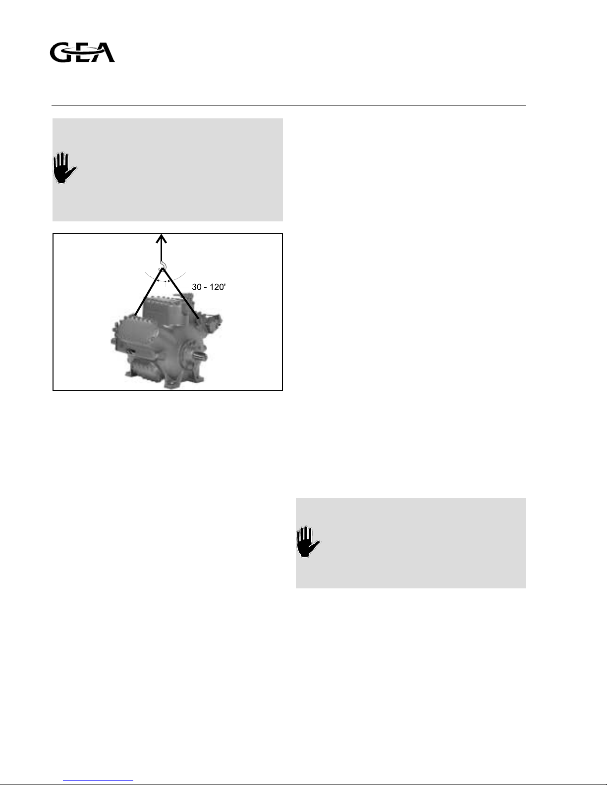
Bare compressor or loose components:
Determine the dead weight of the particular component (see "Engineering
Data"), prior to moving a bare compressor or loose component. Use the hoisting eyes only to lift so, DO NOT sling
from other compressor parts (see figure
A1.1A).
Moving by fork-lift truck
The bare compressor or package can be
transported with a fork-lift truck with the forks
spread as much as possible between the skids. To
simplify moving, the 2 wooden transport beams
must still be mounted underneath the base frame
and stored in this way, untill the package is
positioned above its approximate location.
A1.1.2 Storage
The compressor (package) is filled with dry
nitrogen. Keep the system closed until the
package is
installed. If the compressor (package) is stored, it
should be kept at all times in a dry location to
prevent corrosion damage. If the compressor
(package) is to be stored for a prolonged period
of time, it should be checked weekly to ensure
that the holding charge of dry nitrogen remains
above atmospheric pressure.
A1.2 Required free space
For easy operating, servicing and maintenance
access, the compressor (package) should be at
least installed with sufficient free space around it.
A1.3 Foundation requirements
This paragraph covers measures to be taken for a
compressor (package) on a concrete floor.
Two foundation arrangements are described:
• Compressor package with steel base frame
mounted on a concrete block.
• Bare compressor direct mounted on a concrete
block via grouted machined anchors (see
"Engineering Data"). The mounting surfaces of
these machined anchors must be level without
any deviation and projecting at least 10 mm
above the concrete base.
COMPRESSOR AND COMPRESSOR
PACKAGE TO BE MOUNTED ON A
CONCRETE BLOCK
On request, Grasso can calculate the
exact dimensions of the concrete block,
based on the compressor size and
operating conditions.
Fig. A1.1A Hoisting angle bare shaft compressor
Refrigeration Division
Grasso
A: INSTALLATION AND PREPARATION FOR USE
A1.2 Installation and Maintenance Manual RC(U)6 v001.99.01.en

A1.3.1 Concrete structure
The concrete block for compressor and motor or
compressor package should have a profile as
illustrated in fig. A1.2 and made according to the
following recommendations:
• The concrete block should be set on firm
footings or on a floor capable of carrying the
weight of the concrete block and capable to
absorb the free forces and gas forces of the
compressor during operation. The ground under
the concrete block should be horizontal and flat
(refer to fig. A1.2).
• The top surface of the block should be level and
even.
• There should be sufficient free space around the
block to install corkboard (or similar).
• The block should be provided with anchor bolt
recesses or holes (fig A1.3.) according to the
anchor bolt spacing as per package lay out
drawing.
It is recommended to consult a concrete specialist/
constructor for the following items:
• The compounding of the concrete with/without
reinforcement.
• The exact grouting depth (dependent on the
soil conditions).
• Installing foundation onto an existing floor, with
sealing corkboard or vibration isolators.
Fig. A1.2
Fig. A1.3
1 Corkboard
2 Concrete base
3 Basement floor
A Chemical anchor
B Grouted anchor, grounded to reinforcing steel
Refrigeration Division
Grasso
A: INSTALLATION AND PREPARATION FOR USE
v001.99.01.en Installation and Maintenance Manual RC(U)6 A1.3
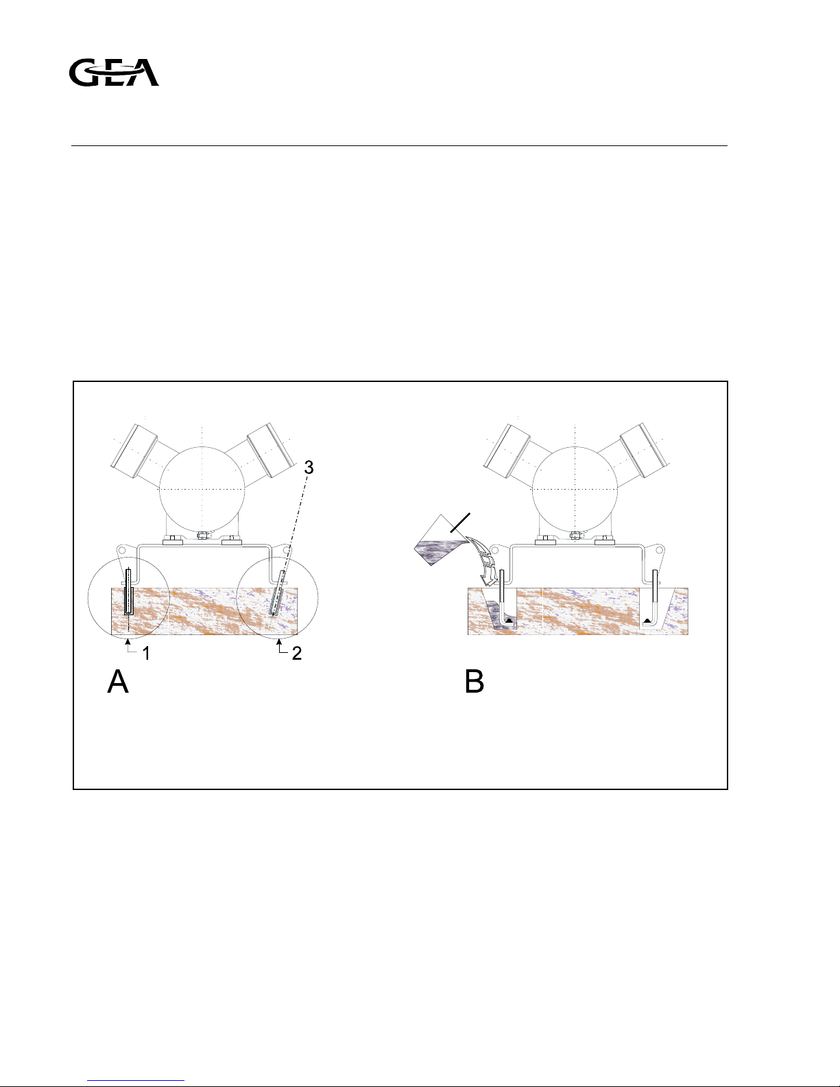
A1.3.2 Anchoring
After the concrete block has cured the anchors
should be installed as shown in figs. A1.3 and/or
A1.4 and in case of a package in accordance with
the package lay out drawing. Templates should be
made to locate the anchor bolts or chemical
anchors to match the holes in the bottom flange
of the base frame.
Grout the mortar as given by the supplier
instructions. Install chemical anchors as illustrated
in figure A1.4 and according the instructions of
the anchor supplier.
A1.4 Concrete block mounting instructions
A1.4.1 Mounting bare compressor on a concrete
block
If no base frame is applied the compressor and
motor should be installed as discussed in §A1.3
and "Engineering Data".
A1.4.2 Mounting the base frame on a concrete
block
General
After the space between base frame and concrete
base is filled-up with a filling grout, the package
base frame must be secured tightly to the
foundation block or floor (refer to fig. A1.3).
Fig. A1.4 Anchoring details
A Drilled chemical anchor (thread size M16)
B Grouted anchor recesses (thread size M16)
1 Installed chemical anchor before placing the base frame
2 Installing chemical anchor after placing the base frame (base
frame cannot removed easily)
3 Drilling angle
Refrigeration Division
Grasso
A: INSTALLATION AND PREPARATION FOR USE
A1.4 Installation and Maintenance Manual RC(U)6 v001.99.01.en
• Levelling the base frame
After the anchor filling mortar is completely cured
the frame should be levelled with a space
between block and lower frame flange of 3 - 5
mm. This space largely depends on the sort of
grout or mortar used. Determine this space as
given in the instructions of the grout or mortar
supplier. This space is necessary for levelling using
the base frame adjusting bolts with metal washers
(supplied separately). The base frame should be
levelled on each frame side. Adjust the frame on
each adjusting place until all frame sides are
horizontal.
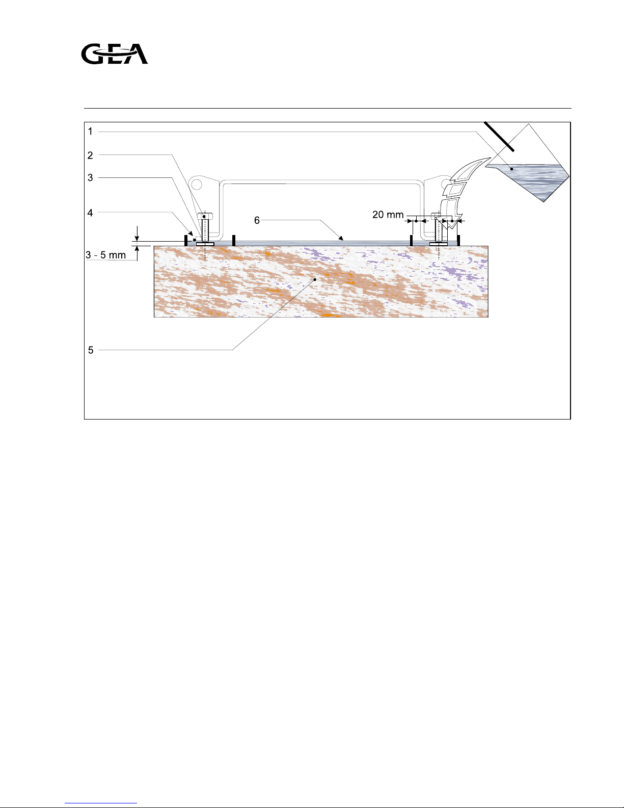
• Finishing with a self-levelling grout (See figure A1.5)
After levelling is completed the adjusting bolt
ends must be greased to avoid bonding to the
self-levelling grout. The space between concrete
block and frame must be completely filled with
the self-levelling grout to ensure that the
complete bottom surface of the base frame will
be supported. Therefore, it is not allowed to use
shims between concrete base and base frame.
Grouting must be carried out in accordance with
the instructions provided by the grouting supplier.
After complete de-aeration of the grouted layer,
secure the base frame by tightening the anchor
bolt nuts and remove all adjusting bolts. At this
stage the drive system can be installed. These
(accessories) installation instructions can be found
in the order manual.
A1.5 Connecting to refrigerating system pipe-
work
After the compressor (package) has been levelled
and secured to the foundation, the system piping
may be connected. The suction line(s) and
discharge line(s) should be installed and supported
such that there is no load exerted on the
compressor. The size and location of the suction
and discharge connections, can be found in the
"Engineering Data" (bare compressor) and in case
of a package, the package lay out drawing.
Fig. A1.5 Grouting details
1 Self-levelling grout
2 Adjusting bolt (4x)
3 Washer
4 Temporary barrier strip around and inside frame
5 Complete cured concrete block
6 Grout layer
Refrigeration Division
Grasso
A: INSTALLATION AND PREPARATION FOR USE
v001.99.01.en Installation and Maintenance Manual RC(U)6 A1.5

If an oil rectifier system is applied in the refrigeration system, the oil return line
must be connected to the oil return connection.
Never connect the oil rectifier return line to
the suction line or to the suction gas filter.
DO NOT ground through the compressor
when arc welding
Suspension of system pipework
To eliminate vibration transmission to the system
piping, the following is recommended:
• Install all piping free of tension.
• Secure the piping by clips or suspenders in two
directions.
• Install (stop) valves, piping and accessories such,
that there is no load exerted on the compressor.
A1.6 Connecting the power supply
Before leaving the factory the compressor
package is completely wired*. The connection to
be made by the installer is between main power
source and the Monitron CR (if ordered).
Information about further electrical connections
to be made (e.g. crankcase heater, drive motor
starting equipment, thermal protection of drive
motor, automatic start/ stop, motor current
transducer and other external electrical devices)
can be found in the order manual.
*
If the standard recommended Monitron CR is applied.
A1.7 Earthing connections
Grasso compressors and packages are equipped
with litz-wires and earth connecting points.
To avoid leakage current flowing through the
components, disconnect all litz-wires when arcwelding. After all installation functions are
completed, reconnect the litz-wires and ground
the package to earth.
A1.8 Separately delivered components
Mount the separately delivered set-components
e.g. oil charge and drain valve, according to the
instruction enclosed in each individual set.
Refrigeration Division
Grasso
A: INSTALLATION AND PREPARATION FOR USE
A1.6 Installation and Maintenance Manual RC(U)6 v001.99.01.en

A2 PREPARATIONS FOR USE
After the Compressor (Package) has been installed
(excl. final connection of drive device), the
following actions should be followed in the order
given:
A2.1 Leak test of compressor and system
The compressor (package) has been pressure
tested prior to leaving the factory. In case an
additional leak test is required, this test is should
be carried out with dry nitrogen under pressure
up to a max. of 10 bar(a).
Do NOT add oil to the compressor prior
to pressure testing.
A system leak test should be carried out over 24
hours to ensure that the system is tightly sealed.
Record during the pressure test, the pressure,
ambient temperature and outside temperature.
During the initial 6 hours a pressure drop of 2% is
permissable. With respect to temperature
variations, no further pressure loss should be
detected in the remaining 18 hours.
If the test pressure has not decreased by more
than 5% the system can be considered leak free.
A2.2 Evacuation/drying the refrigerating system
For evacuation of compressor only, refer to §B5.
Procedure to evacuate and to dry a system:
a) STATUS: System is filled with nitrogen (refer to
§A2.1) and no oil into the system (oil prevents any
trapped moisture from boiling off).
b) Verify that all valves in that part of the system to be
evacuated are opened (refer also to the plant
manual).
c) Connect vacuum pump to the evacuation/purging
valve(s) of the compressor (for location of these
valves refer to the "Engineering Data" or to a
connection as mentioned in the plant manual and
evacuate the system to approx.
5 mm Hg (=6.6 mBar).
d) Break vacuum by charging dry nitrogen into the
system.
e) Repeat step ’c’.
f) Wait approx. 24 hours.
g) If pressure has been increased (system still contains
moisture), repeat steps ’d’, ’e’ and ’f’, otherwise,
continue with the "Initial oil charge" procedure
§A2.3.
A2.3 Initial oil charge
Used or filtered oil should NEVER BE
added to a compressor under any
circumstance.
Use only new oil to be selected from the
oil table (see "Engineering Data").
a) STATUS: System is dried and still evacuated (refer to
§A2.2).
b) Close suction and discharge stop valves of
compressor and oil return line of oil separator
(if present).
c) Fill the compressor crankcase with oil (for oil
quantity see table overleaf) via the oil charge/ drain
valve (for location of this valve refer to the
"Engineering Data").
d) Open evacuation/purging valve(s) of the
compressor (for location of these valves refer to the
"Engineering Data") to bring the compressor to
atmospheric pressure.
e) Fill the following components with oil as given in
the table on the next page with/without pre-
lubrication valves (explained hereafter) :
- Shaft seal housing via the oil filling opening.
- Oil pump housing via the oil filling opening.
- Oil suction and discharge filter housings via the oil
filling openings.
Refrigeration Division
Grasso
A: INSTALLATION AND PREPARATIONS FOR USE
v001.99.01.en Installation and Maintenance Manual RC(U)6 A2.1

A2.4 Initial refrigerant charge
Refrigerant charging should be done in
accordance to the plant manual by qualified
refrigeration engineers.
Oil charging via the suction line of the
compressor is not allowed.
A2.5 Adjustment of instruments and safety
devices
A2.5.1 Monitron
For adjustments see table overleaf.
A2.5.2 Pressure safety switches
Refer to the table overleaf. Setting procedures are
described in the Safety Switch supplier instructions.
QUANTITY OF OIL TO BE FILLED (in dm3)
Compressor series RC6 Shaft seal housing Oil filters Oil pump Crankcase
RC46
± 0.5 ± 1.0 ± 0.5
11
RC66 12
RC86 13
Refrigeration Division
Grasso
A: INSTALLATION AND PREPARATIONS FOR USE
A2.2 Installation and Maintenance Manual RC(U)6 v001.99.01.en
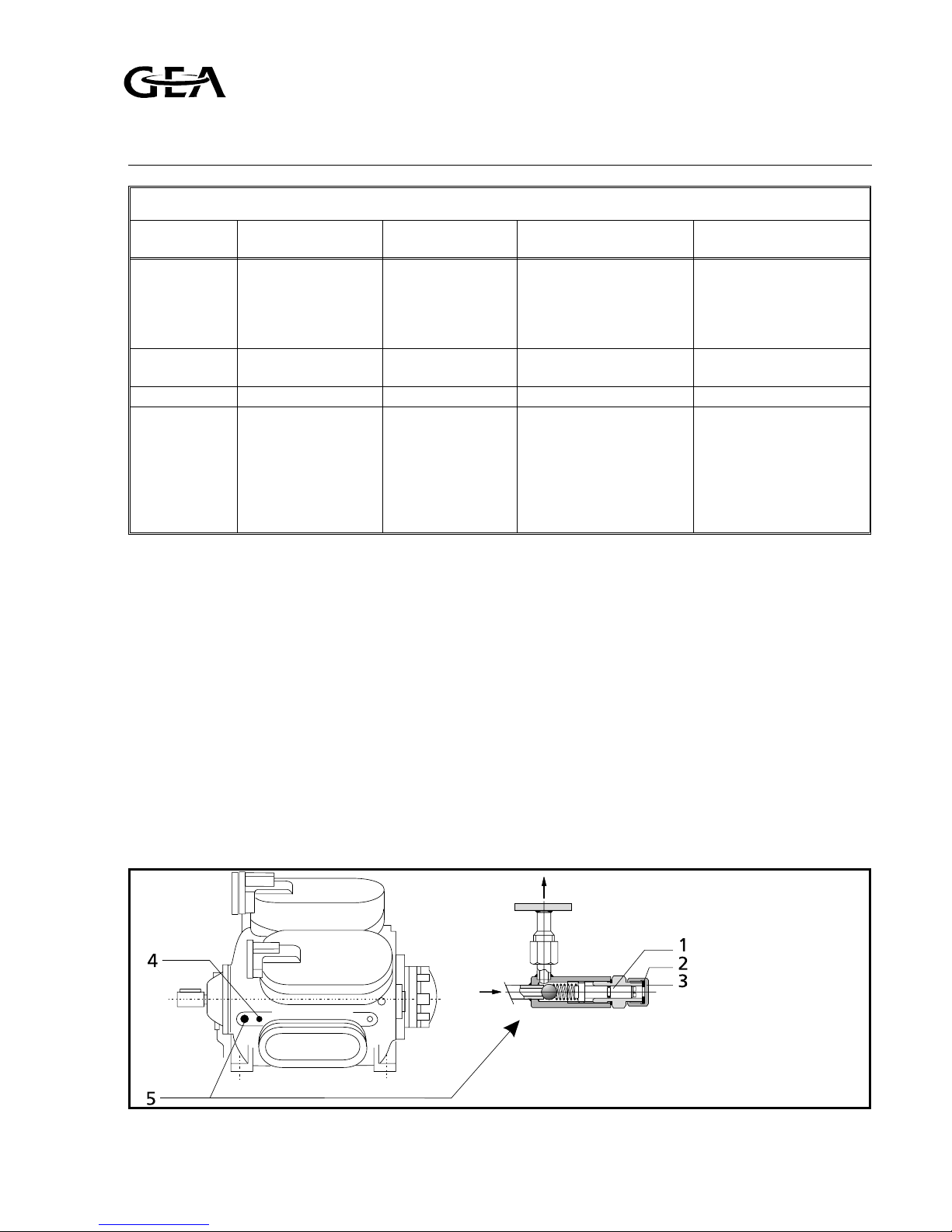
A2.5.3 Re-adjustment of oil pressure regulator (re-
fer to fig. A2.1)
Re-adjustment procedure:
a) Run the compressor for 15 minutes until the
crankcase oil is at its stable operating temperature [Toil].
b) Determine the oil pressure difference (difference
between the pressure gauges of the oil and suction
or [dOil]).
c) After approx. 15 minutes of operatinf and an oil
temperature of 50 °C, the oil pressure difference
should be approx. 2.0-2.5 bar.
During these first minutes the pressure should be
slightly higher.
d) Remove the cap nut (3) with alu ring (2), of the oil
pressure regulator if the pressure needs to be
re-adjusted.
e) Turn the slotted pin (1) with a screwdriver clockwise
or counter clockwise for a higher or lower oil
pressure respectively, until the required oil pressure
differences has been achieved.
f) Replace the cap nut (3) with alu ring (2).
Settings of compulsory pressure safeties
Read-out
Monitron
1
)
Description Min. value Max. value (pre)-Setting
Psuc Suction pressure 0.3 bar (4.4 psia) NH3 6.2 bar (90 Psia)
R22 6.8 bar (99 Psia)
R134a 6.2 bar (90 Psia)
R404A 6.0 bar (87 Psia)
R507 5.8 bar (84 Psia)
5 °C (9 °F) below design
evaporating temperature
Pdis Discharge pressure > Psuc 26.0 bar (377 Psia) 5 °C (9 °F) above design
condensing temperature
Pdis-Psuc > 0 bar 24.0 bar (348 Psia) < 24.0 bar (348 Psia)
dPoil Lubrication oil
pressure difference
1.5 bar (22 Psia) 2.5 bar (36 Psia) The oil pressure
regulator is adjusted at
the works, but it may
occur that this setting
should be corrected
during the initial run
(see A2.5.3)
1
)In case of Monitron the values are measured via pressure transducers, otherwise protection via switches is compulsory.
Fig. A2.1 Oil pressure regulator
1 slotted pin
2 alu ring
3 cap nut
4 return from oil separator
or oil rectifier
5 oil pressure regulator
Refrigeration Division
Grasso
A: INSTALLATION AND PREPARATIONS FOR USE
v001.99.01.en Installation and Maintenance Manual RC(U)6 A2.3

A2.6 Checking direction of rotation of motor shaft
Prior to installing the intermediate coupling element
or V-belts, the direction of rotation of the motor
shaft must be checked either by bumping the
electrical drive motor or by measuring the rotation
of the field (direction of rotation normally counter
clockwise when facing compressor shaft end).
A2.7 Installing the (drive) guards (if present)
Only after the compressor is ready for the initial
startup! Refer to the drive guard installing
procedures included in the order documentation.
A2.8 Initial oil warm up
Prior to the initial start-up (refer to §A2.9), the
crankcase heater (if present) must be energized. For
the min. oil temperature (min. [Toil]) refer to page VII.
A2.9 Initial start-up
A2.9.1 Limitations of part load operation and
start-up
The capacity control serves to adapt the compressor
capacity at any moment as closely as possible to the
refrigerating capacity. In order to adapt the capacity,
a number of cylinders can be put in or out of action
either individually or collectively.
Due to start-up limitations and to
limitations of part load operation it may
be that not all available part load steps
are allowed under certain conditions.
Use of incorrect control steps can
damage compressor and/or components.
In the case of a Monitron Controller, all these
limitations will be checked automatically.
For a detailed description about these start-up
and part load limitations refer to the "Engineering
Data".
A2.9.2 Pre-start check list
The following Paragraph covers only the initial
start of the compressor and not the complete
refrigeration plant.
Be sure that all necessary system valves are open
and that the refrigeration system is ready for start
up. Use the following check to guarantee that no
items of importance regarding the compressor
(package) have been overlooked.
a) System is charged with refrigerant.
b) Monitron (if present) is properly installed (refer to
the Monitron Instruction Manual).
c) Settings of safety limit switches are adjusted properly.
d) Direction of rotation of compressor crankshaft is
correct.
e) Oil level established in sight glass.
f) Stop valves to the pressure gauges are open (if
present).
g) Suction stop valve is closed (in case the evaporating
temperature is much higher than the design
evaporating temperature) and the discharge stop
valve is open.
h) Stop valve in the oil return line of the oil separator
(if present) is closed.
When all items a) through h) are verified, the
compressor (package) is ready for the start-up.
A2.10 Starting and stopping procedures
When starting the compressor a distinction should
be made between:
A2.10.1 Starting for the very first time (between
brackets [ ] are Monitron units)
a) Notice §A2.9.2 "Pre-start check list", consult also the
plant manual and verify the following items:
- Check the oil temperature [Toil] (refer to the
"Engineering Data").
- Check crankcase oil level (refer to §B4.1).
b) Start the compressor and check whether the oil
pressure [Poil] increases.
Maximum 6 starts per hour and at least 2
minutes between stopping and starting
and at least 10 minutes between starting
and re-starting
Refrigeration Division
Grasso
A: INSTALLATION AND PREPARATIONS FOR USE
A2.4 Installation and Maintenance Manual RC(U)6 v001.99.01.en

c) Slowly open suction stop valve and watch suction
pressure [Psuc], which may not exceed the max.
value as given for each refrigerant in §A2.5.2.
Refrigerant liquid hammer, will damage
the compressor;
Superheat is always necessary! [dTo]≥5 K
d) More cylinders will be energized.
Watch maximum allowable motor current
[Imot] (refer to motor type plate).
e) Adjust pressure gauge stop valves, in order to avoid
vibration of the pointers (if present).
f) Open the stop valve in the oil return line from the
oil separator (if present).
Retighten the coupling bolts or check or
correct the tension of the V-belts and
retighten the foundation bolts (with
due respect to the torque settings given
by the supplier of the fasteners!) after
50 hours of operation.
A2.10.2 Restart (not within 2 minutes after a
stop, respectively starting after a short
standstill period of time [les than 1
month]). If Monitron Controlled, refer to
the Monitron Instruction manual)
• Proceed to the starting procedure of §A2.10.1
point a), b) and d).
A2.10.3 Starting after a seasonal standstill (1 till
6 months) or maintenance operations
• Check settings of control and safety equipment
(refer to §A2.5).
• Proceed to the complete starting procedure of
§A2.10.1, items a) through f).
A2.10.4 Starting after a long standstill period of
time (more than 6 months)
Consult your supplier. Monitron "standby" status
(ready to operate during this long period of time)
is not allowed! It is recommended to
proceed with the "Initial start-up" procedure of
§A2.10.1.
A2.10.5 Stopping the compressor
The compressor can be stopped at any moment,
however, consult the supplier if further actions are
required.
Refrigeration Division
Grasso
A: INSTALLATION AND PREPARATIONS FOR USE
v001.99.01.en Installation and Maintenance Manual RC(U)6 A2.5

Refrigeration Division
Grasso
A: INSTALLATION AND PREPARATIONS FOR USE
A2.6 Installation and Maintenance Manual RC(U)6 v001.99.01.en

SUBJECT Page no.:
SECTION B: INSPECTION, MAINTENANCE AND TROUBLE SHOOTING ....................................... B1.1
B1 INSPECTION ................................................................................................................................ B1.1
B1.1 Periodical inspection ......................................................................................................... B1.1
B1.2 Survey of periodical inspections ....................................................................................... B1.1
B2 MAINTENANCE .......................................................................................................................... B1.2
B2.1 Post start-up maintenance ............................................................................................... B1.2
B2.2 First maintenance ............................................................................................................. B1.3
B3 STEPS FOR LONGER SHUT-DOWN PERIODS (more than 6 months) ....................................... B1.4
B4 LUBRICATION DATA .................................................................................................................. B1.4
B4.1 Topping up oil with compressor operating .................................................................... B1.4
B5 EVACUATION OF THE COMPRESSOR ....................................................................................... B1.5
B6 DRAINING AND CHANGE OF OIL ............................................................................................. B1.5
B7 CLEANING OF OIL FILTERS ........................................................................................................ B1.5
B8 CLEANING OF SUCTION GAS FILTER(S) .................................................................................... B1.6
B9 DISMANTLING, INSPECTION AND RE-ASSEMBLY OF SUCTION AND DISCHARGE VALVES .. B1.6
B10 COMPRESSOR PURGING ............................................................................................................ B1.7
B11 TROUBLE SHOOTING TABLE .....................................................................................................B1.7
Refrigeration Division
Grasso
TABLE OF CONTENTS
v001.99.01.en Installation and Maintenance Manual RC(U)6 B.I

Refrigeration Division
Grasso
TABLE OF CONTENTS
B.II Installation and Maintenance Manual RC(U)6 v001.99.01.en
B1 INSPECTION
B1.1 Periodical inspection
These inspections should be made during the normal
shut-down periods as much as possible, so the
compressor is always ready to operate when required. If,
at that time, the number of running hours slightly differs
from the scheduled period below, the inspection should
nevertheless be carried out.
In this way it will not be necessary to stop the
compressor at inconvenient times.
The frequency of inspections is dependent on the type
of installation and operating conditions. In the case of
automatically controlled plants, the periodical inspection
are particularly important. The table below sums up all
the points on the compressor that have to be inspected
or maintained along with inspection and maintenance
frequencies.
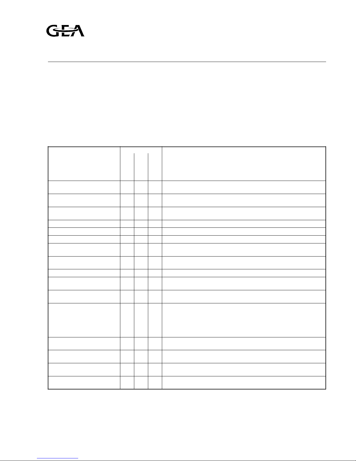
B1.2 Survey of periodical inspections ("check list")
CHECK POINTS 1) FREQUENCY REMARKS
daily
weekly
monthly
Oil level in crankcase
•
Between 25% and 75% height of the sight glass. For topping up oil, refer to
§B4.1.
Colour of the oil
•
The oil should be transparently clear. A disappearing white colour points to
dissolved refrigerant. Refer to § B2.2 for oil analysis frequency.
Lubricating oil pressure difference [dOil]
•
The indication of the oil pressure gauge should be 1.5 - 2.5 bar higher than
the value shown by the suction pressure gauge.
Oil temperature max. [Toil]
•
Refer to the "Engineering Data".
Oil leakage of shaft seal max.
•
In case of more than 1 cc/hr contact supplier.
Suction pressure [Psuc]
•
Check against design conditions. Refer to plant manual.
Discharge pressure [Pdis]
•
Refer to plant manual. For the max. allowable discharge pressure refer to the
technical data of compressor.
Suction superheat [dTo]
Intermediate superheat [dTm]
•
³ 5 K
Discharge temperature max.
•
155 °C (311 °F)
Cooling water temperature (if
present) min.
•
Actual condensing temperature + 10 K.
Oil temperature min. [Toil]
•
During compressor standstill the lower part of the crankcase must remain
warmer than the surroundings: ³ 20 °C (NH
3
) and³30 °C (halocarbons).
Condition of V-belts
•
Check belts for:
1) Wear (fraying, cuts etc.) and ensure that they do not touch the groove
bottom.
2) Tension. Too low a tension gives rise to excessive flapping or oscillation in
operation. For correct tension consult the instructions given by the V-belt
supplier.
Adjustment and operation of
pressure safety switches
•
Refer to §A2.5 and to instructions of switch manufacturer.
Capacity control
•
The time lag between the unloading and loading of one cylinder or cylinder
group should generally be at least 3 - 5 minutes.
Switching frequency of the compressor
•
The time interval between stopping and starting should be at least 2 minutes
and between starting and restarting 10 minutes (see §A2.10.2).
Number of operating hours
•
Check the number of operating hours in view of any maintenance operations
to be carried out.
Apart from the above check points, the sound produced by the compressor provides an indication or its mechanical condition. If
abnormal sounds are audible, their cause should be traced and removed immediately in order to prevent serious breakdowns.
1
) During the first 50 operating hours the compressor should be checked regularly for all the points mentioned above, at least
twice every 24 hours and more frequently in cases where irregularities are found.
Refrigeration Division
Grasso
B: INSPECTION, MAINTENANCE
AND TROUBLE SHOOTING
v001.99.01.en Installation and Maintenance Manual RC(U)6 B1.1

B2 MAINTENANCE (Contractor’s level)
B2.1 Post start-up maintenance
After the compressor has run for the initial 100
operating hours:
a) Drain the oil and refill the compressor with the
correct amount of fresh oil.
b) Exchange or clean the oil discharge filter element.
c) Exchange or clean oil suction filter element (pos 24
of fig. 2.1) as given in §B7.
d) Clean suction gas filter.
e) Check the compressor shaft seal for leakage.
If excessive (more than 1 cc/hr) replace the seal.
f) Check drive
f1) Retighten the coupling mounting bolts with the
torque settings as given by the coupling
manufacturer.
f2) Verify and if necessary, correct the tension of
the V-belts as given in the V-belt supplier’s
instructions.
g) Verify and if necessary, correct the torque settings
of all foundation bolts as given in § 7.2 of the
Compressor Service Instruction Manual.
Refrigeration Division
Grasso
B: INSPECTION, MAINTENANCE
AND TROUBLE SHOOTING
B1.2 Installation and Maintenance Manual RC(U)6 v001.99.01.en
 Loading...