

Page 1
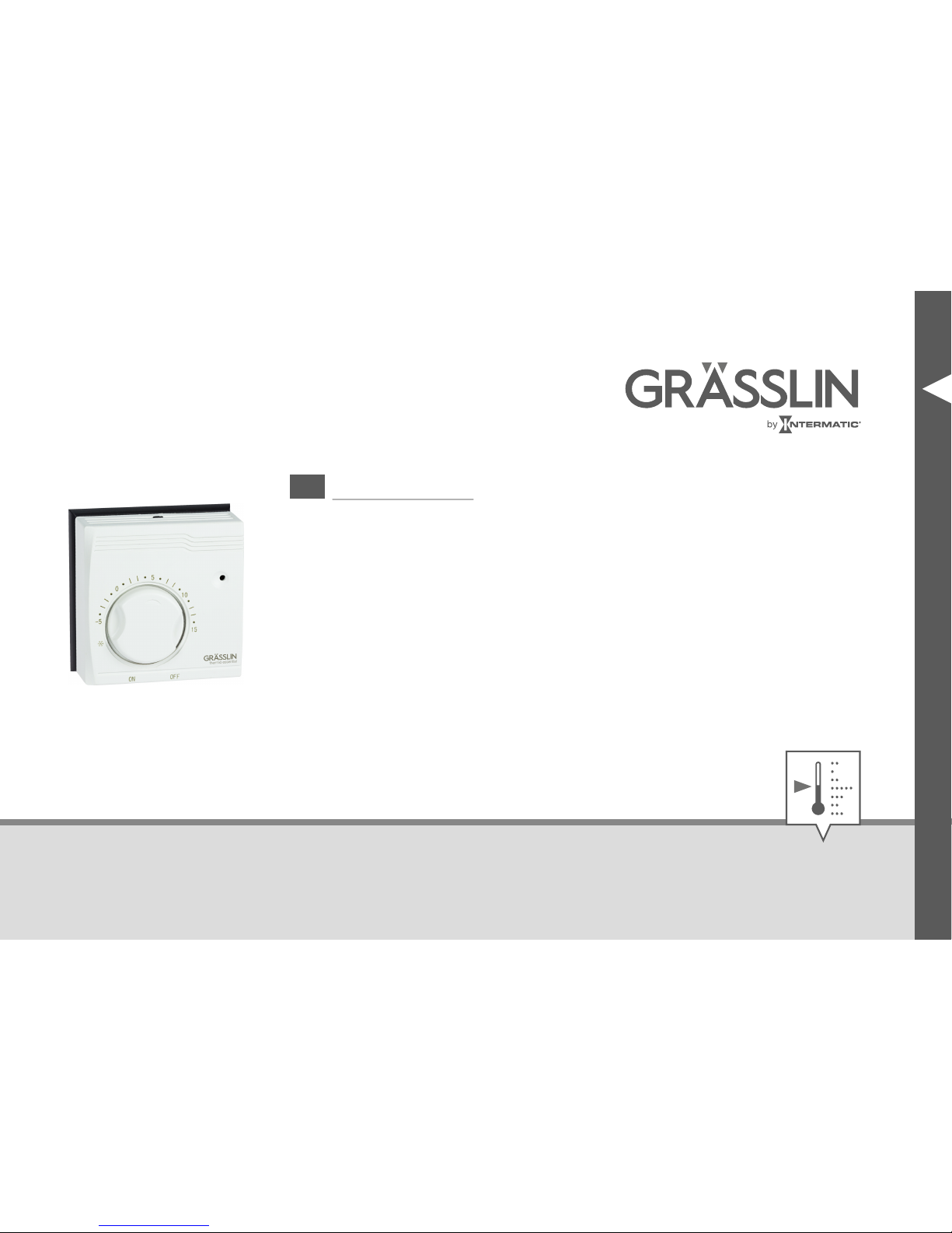
thermio™ essential BFT
EN
Operating manual
Page 2
This manual ensures safe and efficient use of the “thermio™ essential BFT” frost thermostat (referred
to as “device” in the following). This manual is a component of the device and must remain accessible
at all times for everyone who uses the device.
Everyone who uses the device must have read and understood this manual before commencing any
work. The basic prerequisite for working safely is compliance with all safety instructions and usage
instructions specified in this manual. Furthermore, the local accident prevention regulations and the
general safety regulations in the area in which the device is operated apply.
Copyright
This manual is copyright protected.
Handover of this manual to third parties, reproductions of any type and form – including excerpts – and
use and/or disclosure of the content without the written permission of Grässlin GmbH (referred to as
“manufacturer” in the following), except for internal purposes, is not permitted. Violations will result in
liability for compensation. The manufacturer reserves the right to assert additional claims.
The copyright is held by the manufacturer.
2
Page 3
© Grässlin GmbH
Bundesstr. 36
78112 St. Georgen
GERMANY
Download
You can find the following information at
www.graesslin.de
:
• Declaration of conformity
• Download instructions
• Technical data
EN
3
Page 4
Overview................................................................................................. 5
Safety..................................................................................................... 7
Installation.............................................................................................. 8
Setting up the device............................................................................................................ 9
Installation in a flush-mounted socket................................................................................. 14
On-wall mounting............................................................................................................... 19
Operation............................................................................................. 21
Switching on the frost thermostat....................................................................................... 21
Setting the temperature setpoint......................................................................................... 21
Switching off the frost thermostat....................................................................................... 22
Disposal................................................................................................ 23
4
Page 5
Overview
Design
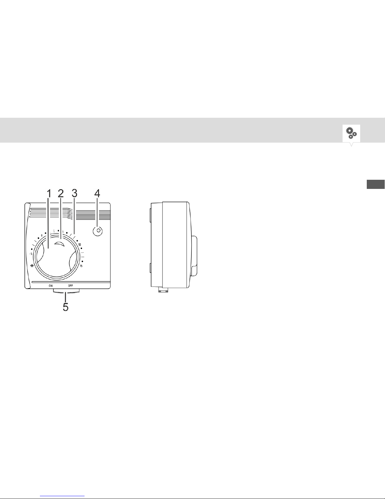
Fig. 1: Front and side view of the “thermio™ essential BFT”
EN
5
Page 6
1 Temperature adjustment knob for temperature setpoint
2 Indicator marker
3 Clearly marked dial
4 Status lamp (lit when device is in operation)
5 Manual switch for switching on and off (ON/OFF)
Description of function
The “thermio™ essential BFT” frost thermostat is an analogue thermostat. The device protects central
boilers or pipes from freezing at low room temperatures by regulating to a set temperature setpoint.
The temperature adjustment knob can be locked to prevent unauthorised adjustment of the temperature
setpoint.
6
Page 7
Safety
Intended use
• The device may only be used for regulating the temperature (-5°C to +15°C) of indoor heating systems.
• The device has the following areas of application: Boilers, heating systems, water pipes and cylinders.
Intended use also includes compliance with all the specifications in this manual. Any use other than the
intended use is considered incorrect use.
Residual risks
WARNING!
Danger to life due to electric shock!
Improper assembly and installation of the device can lead to life-threatening
electrical voltages.
− Have assembly and connection performed by a qualified electrician only.
EN
7
Page 8
Installation
Installation location
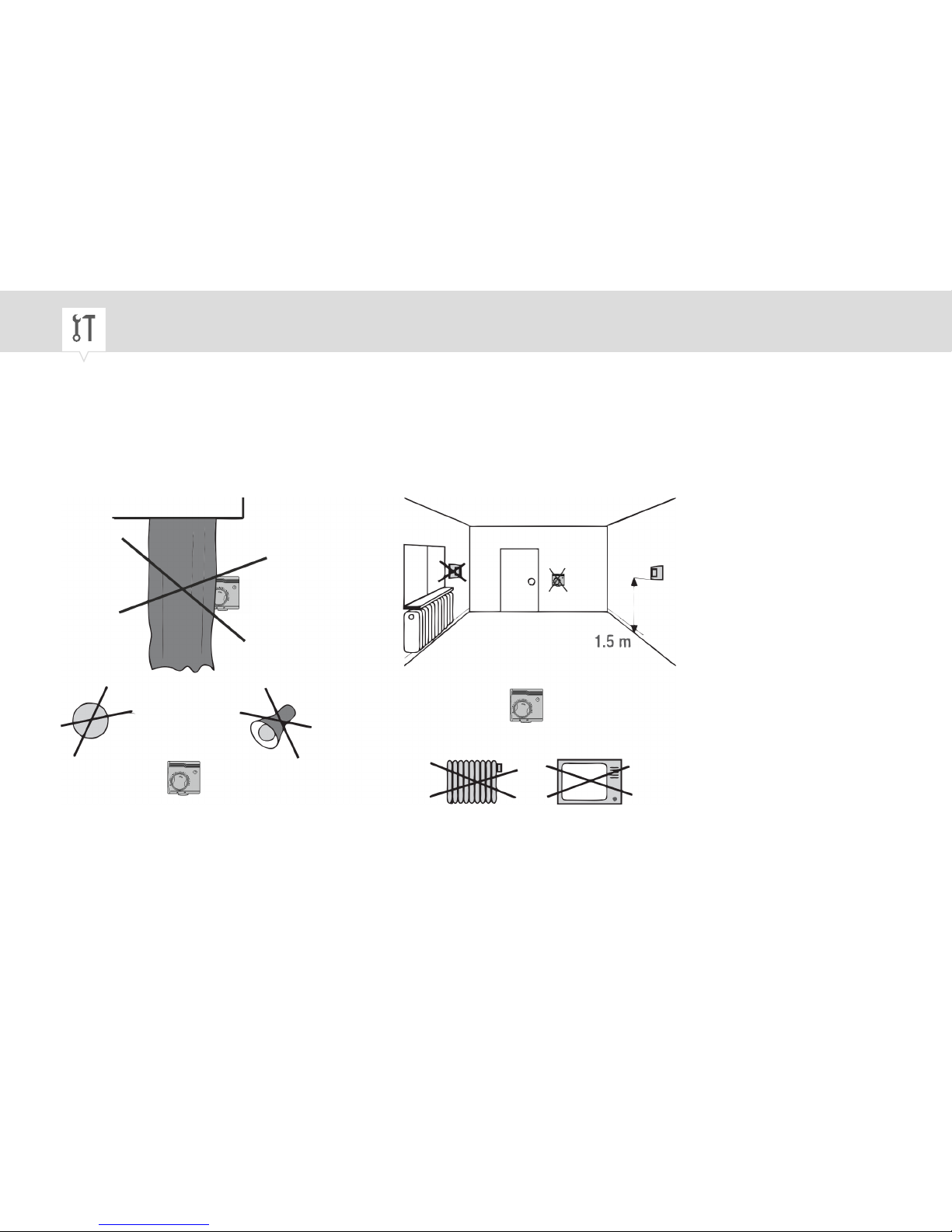
In order to ensure fault-free measurement by the device, choose the right installation location.
Fig. 2: Installation location requirements
8
Page 9
Setting up the device
Personnel:
• Qualified electrician
Special tool:
• Flat-head screwdriver
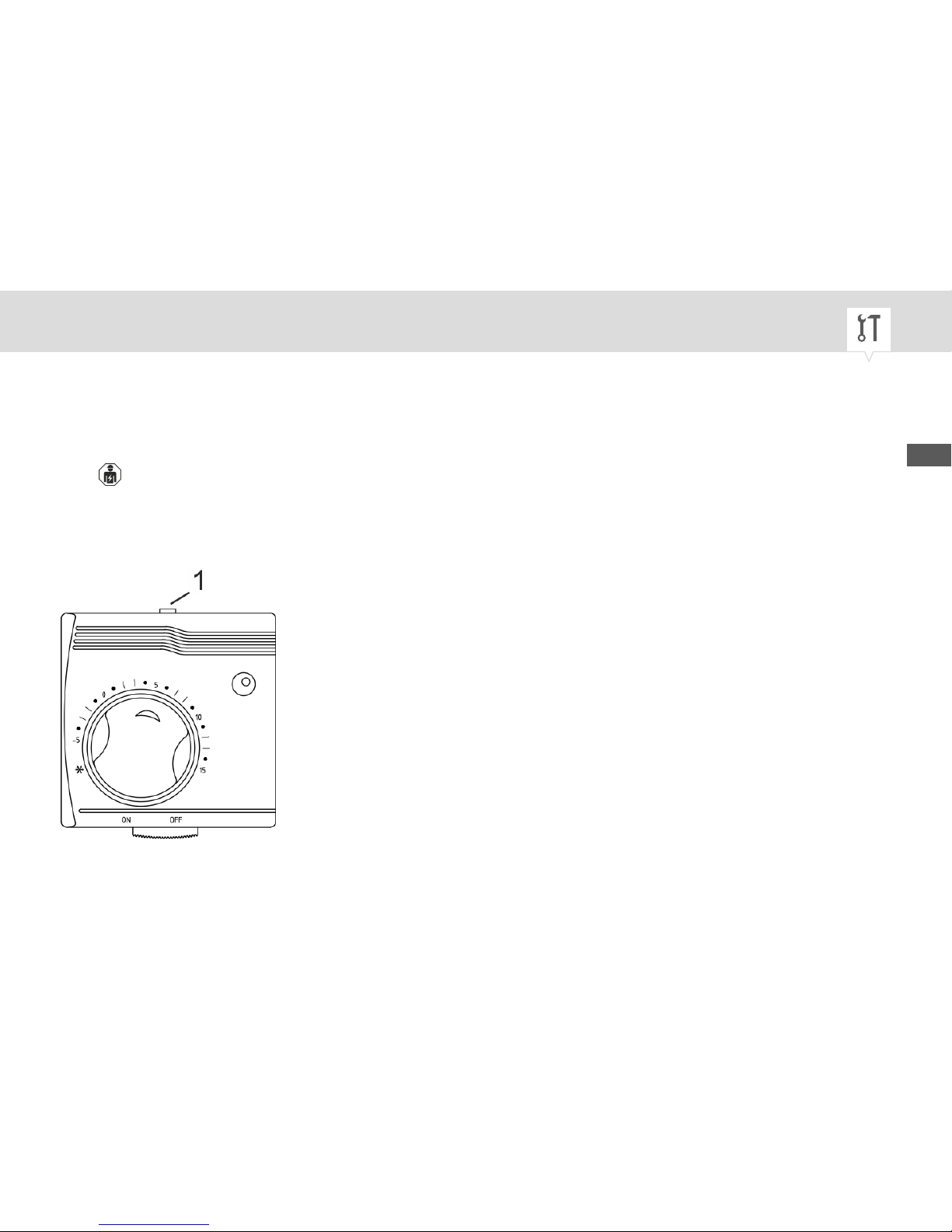
Fig. 3: Removing the housing cover
EN
9
Page 10
1. Push down the engagement hook (Fig. 3/1) on the top of the device and pull the housing cover
forward to remove.
Setting the temperature setpoint
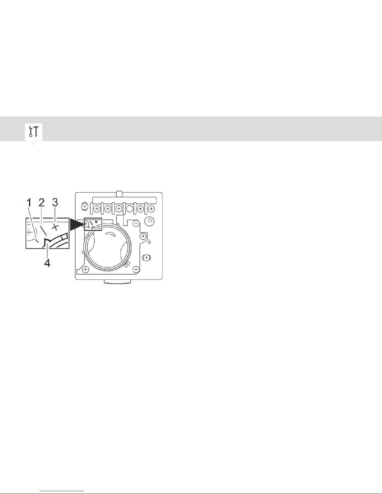
Fig. 4: Marking of the recommended temperature setpoint
10
Page 11
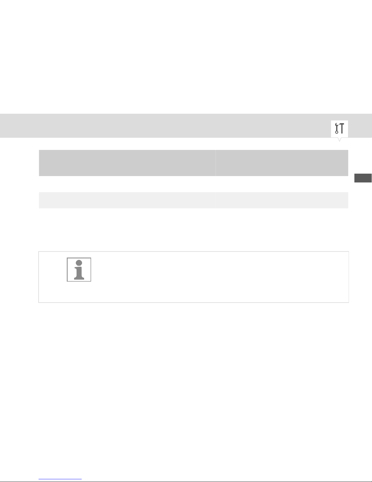
2.
Recommended tem‐
perature setpoint
Marking Number
4 °C | (Fig. 4/1)
5 °C
½
(Fig. 4/2)
6 °C + (Fig. 4/3)
For the required temperature setpoint, turn the triangle on the temperature adjustment knob
(Fig. 4/4) to the relevant marking (|, ½ or +).
If you want to set a different temperature setpoint, put the housing cover
back (but do not engage it) and set the temperature setpoint with the
temperature adjustment knob and the clearly marked dial. Then remove
the housing cover again.
EN
11
Page 12
Locking the temperature setpoint (optional)
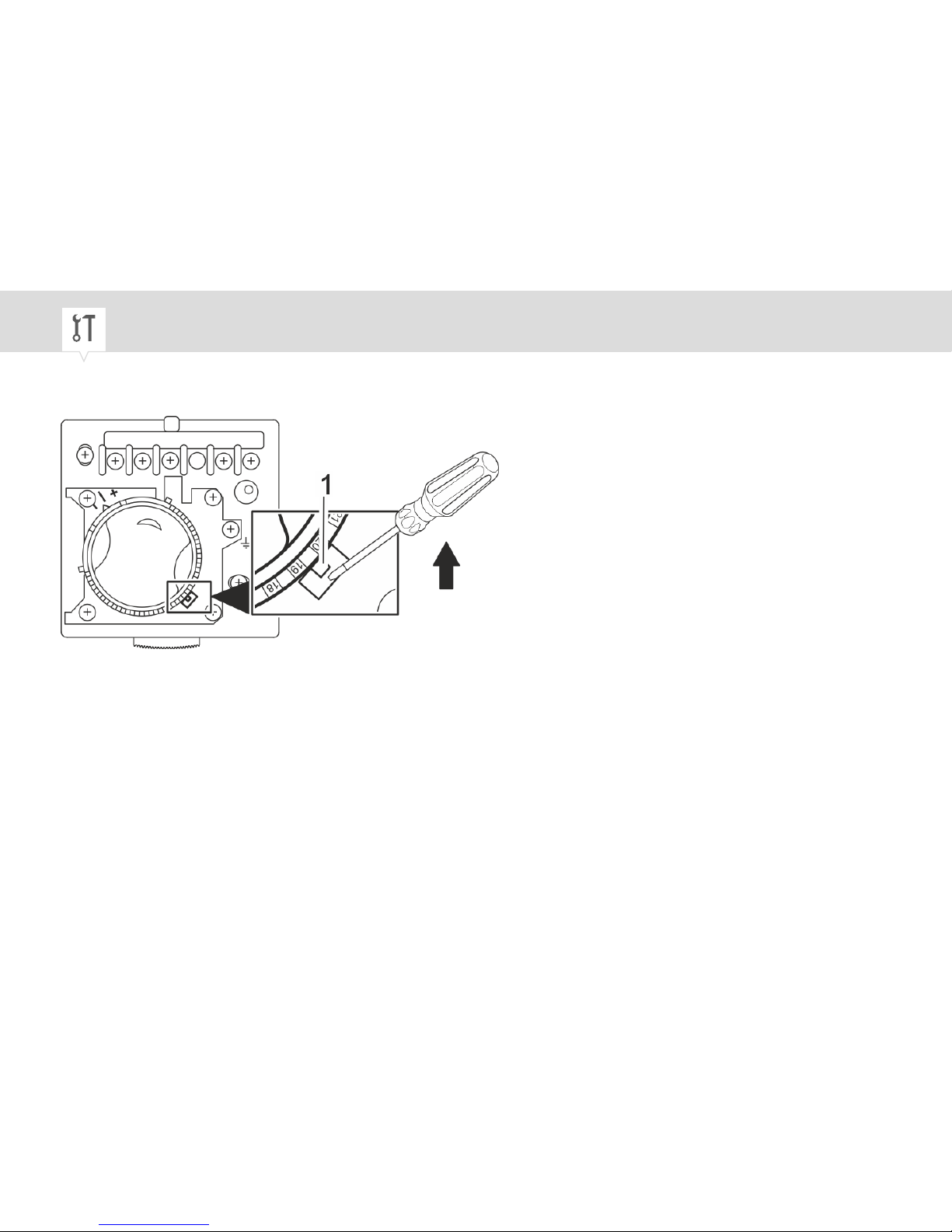
Fig. 5: Locking the temperature setpoint
3. Bend the latch (Fig. 5/1) inwards with a flat-head screwdriver until it is stuck in an increment of the
temperature adjustment knob.
12
Page 13
The recommended temperature setpoints correspond to the following
increments:
− 4 °C corresponds to 18 – 19
− 5 °C corresponds to 19 – 20
− 6 °C corresponds to 20 – 21
ð
The temperature adjustment knob is locked.
EN
13
Page 14
Installation in a flush-mounted socket
Personnel:
• Qualified electrician
Installing the mounting plate
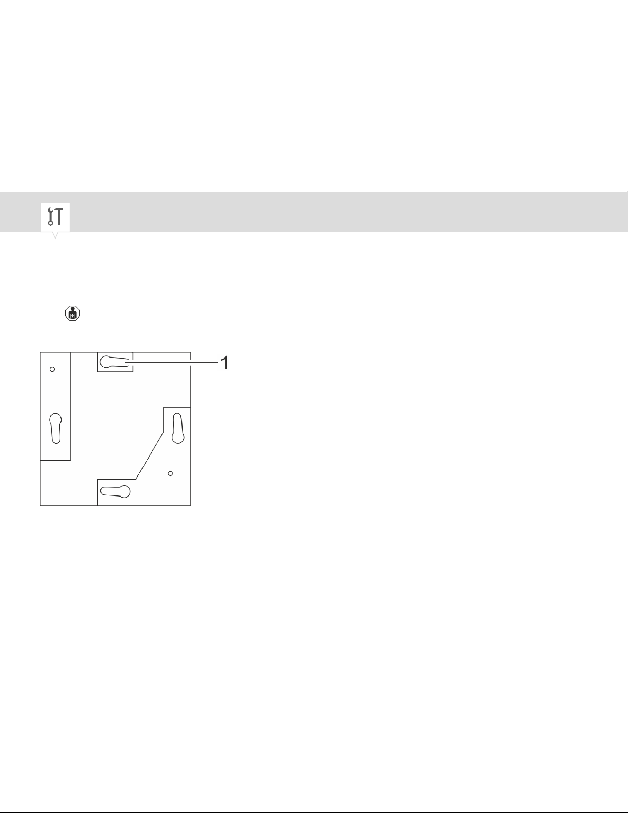
Fig. 6: Mounting plate of the thermio BFT
1. Align the mounting plate so that the “separate” slot (Fig. 6/1) is at the top.
2. Attach the mounting plate to the flush-mounted socket with the screws (3.5 x 20 mm).
14
Page 15
Electric connections
3. Strip the connection wires to a length of 8 mm (cross-section between 1 mm² and 3.5 mm²).
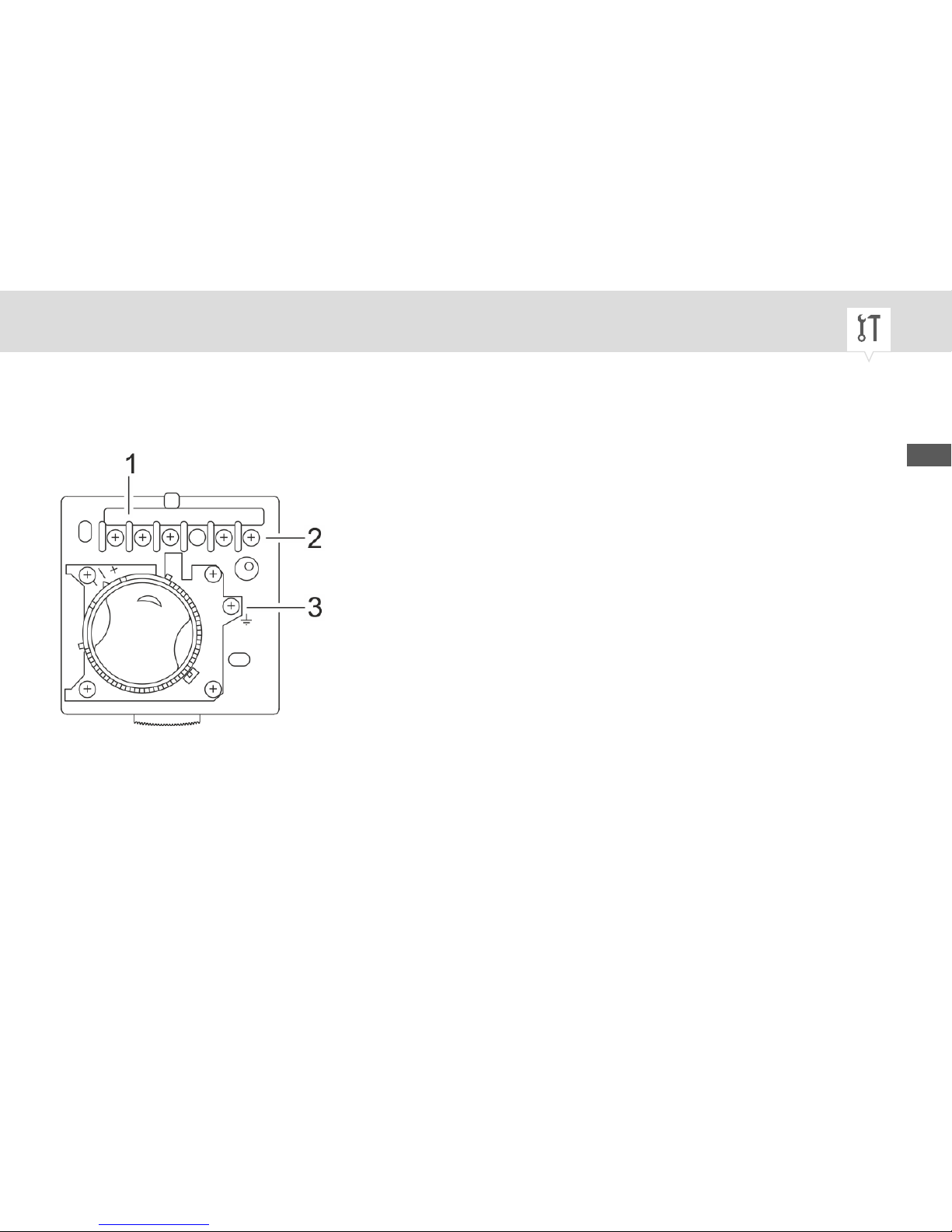
Fig. 7: Cable feed-through and terminal strip
1 Cable feed-through
2 Electrical connections
3 Earth
4. Thread the connection wires into the device through the cable feed-through (Fig. 7/1).
EN
15
Page 16
To ensure that the wiring is correct, consult the operating manual for the
heating system in use.
The devices have protection class 1, so earthing is essential. Connect the
earth correctly.
16
Page 17
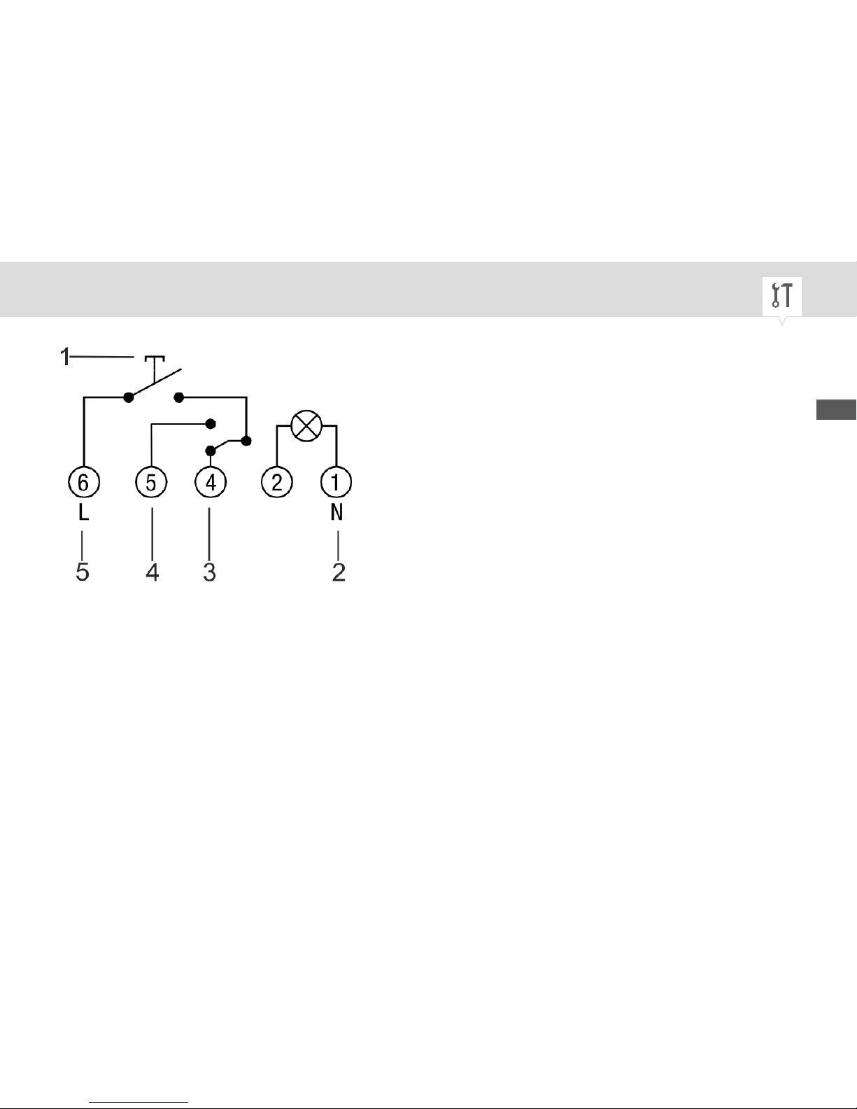
Fig. 8: Wiring diagram
1 On/off switch
2 Neutral conductor
3 NC (normally closed contact)
4 NO (normally open contact)
5 Live conductor
5. Insert the connection wires into the corresponding terminal (Fig. 7/2) in accordance with the wiring
diagram (Fig. 8) and tighten them with 0.6 Nm.
EN
17
Page 18
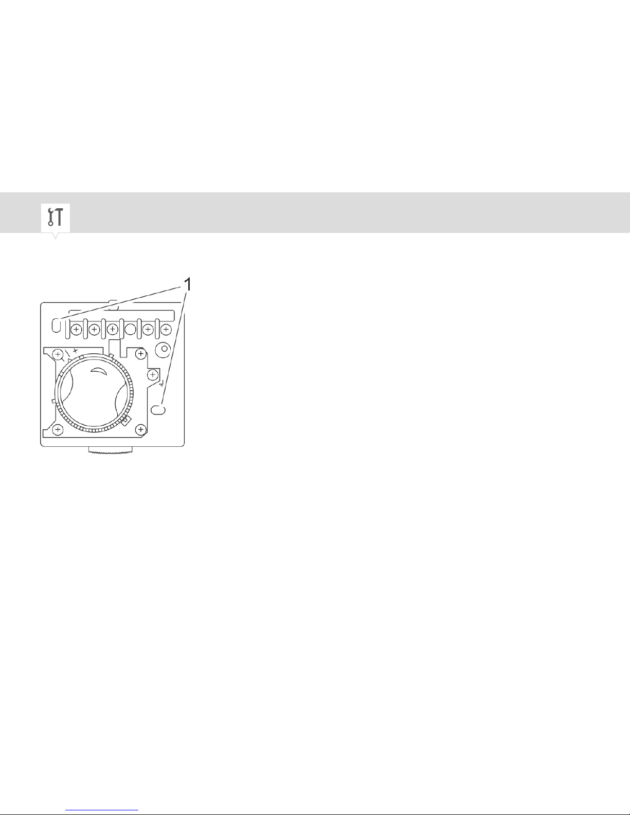
Installing the housing base
Fig. 9: Attaching the housing base
6. Attach the housing base to the mounting plate with screws (3.0 x 15 mm) via the holes (Fig. 9/1).
Closing the housing
7. Place the housing cover on the housing base and engage the engagement hook.
18
Page 19
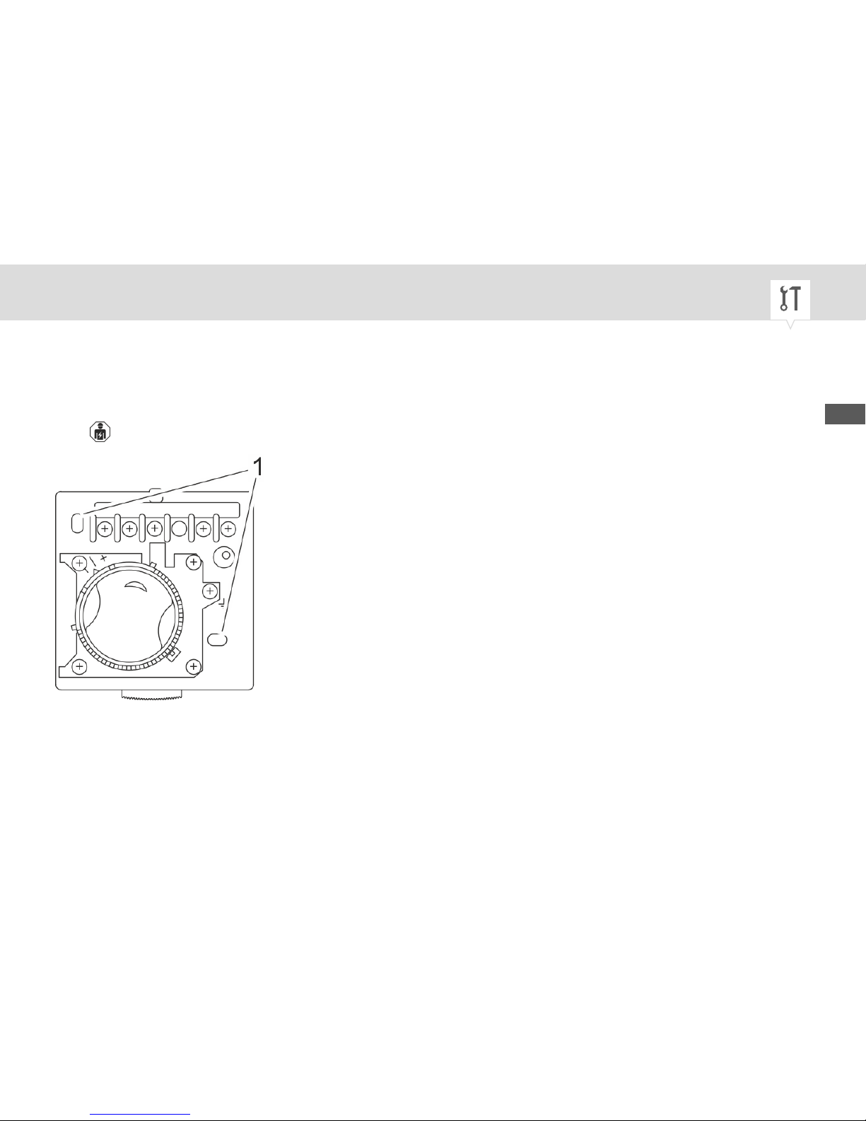
On-wall mounting
Personnel:
• Qualified electrician
Fig. 10: Transferring the hole pattern
1. Mark the hole pattern of the housing base (Fig. 10/1) onto the wall and drill holes at the points you
marked (5 mm diameter and at least 25 mm deep).
EN
19
Page 20
2. Insert suitable wall-plugs into the holes.
Electric connections
3. Strip the connection wires to a length of 8 mm (cross-section between 1 mm² and 3.5 mm²).
4. Thread the connection wires into the device through the cable feed-through (Fig. 7/1).
To ensure that the wiring is correct, consult the operating manual for the
heating system in use.
The devices have protection class 1, so earthing is essential. Connect the
earth correctly.
5. Insert the connection wires into the corresponding terminal (Fig. 7/2) in accordance with the wiring
diagram (Fig. 8) and tighten them with 0.6 Nm.
Installing the housing base
6. Fasten the housing base to the wall-plugs with the screws (3.0 x 20 mm).
7. Place the housing cover on the housing base and engage the engagement hook.
20
Page 21
Operation
Switching on the frost thermostat
Personnel:
• User
1. To switch on the device, turn the manual switch (Fig. 1/5) to ON.
Setting the temperature setpoint
The temperature setpoint can only be adjusted or modified if the temperature
adjustment knob was not locked during installation Ä Chapter "Setting up
the device" on page 9.
Personnel:
• User
1. Turn the temperature adjustment knob (Fig. 1/1) so that the indicator marker (Fig. 1/2) points to the
temperature setpoint.
EN
21
Page 22
Switching off the frost thermostat
Personnel:
• User
1. To switch off the device, turn the manual switch (Fig. 1/5) to OFF.
22
Page 23
Disposal
Improper disposal
ENVIRONMENT!
Incorrect disposal presents an environmental danger.
Incorrect disposal could result in environmental dangers.
− Electric scrap and electronic components must be disposed of correctly,
i.e. the parts for disposal must be sorted into material groups.
− Disposal must be environmentally responsible and must employ stateof-the-art environmental protection, recycling and disposal technology.
EN
23
Page 24

80.10.1471.7/0417/V01
Grässlin GmbH
Bundesstrasse 36
78112 St. Georgen
GERMANY
Telephone: +49 7724 933-0
Fax: +49 7724 933-240
Email: [email protected]
Internet: www.graesslin.de
 Loading...