

Page 1
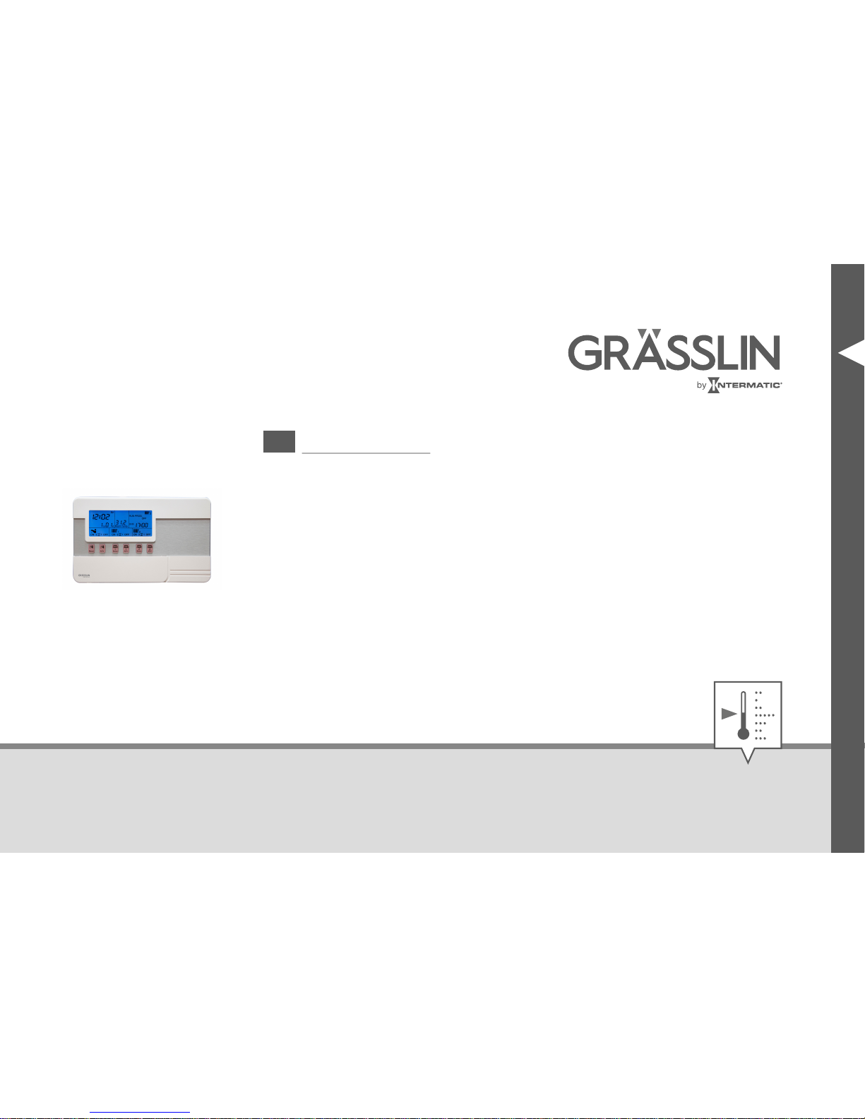
thermio™ eco C3
EN
Operating manual
Page 2
This manual ensures safe and efficient use of the “thermio™ eco C3” thermostat (referred to as
“device” in the following). This manual is a component of the device and must remain accessible at all
times for everyone who uses the device.
Everyone who uses the device must have read and understood this manual before commencing any
work. The basic prerequisite for working safely is compliance with all safety instructions and usage
instructions specified in this manual. Furthermore, the local accident prevention regulations and the
general safety regulations in the area in which the device is operated apply.
Copyright
This manual is copyright protected.
Handover of this manual to third parties, reproductions of any type and form – including excerpts – and
use and/or disclosure of the content without the written permission of Grässlin GmbH (referred to as
“manufacturer” in the following), except for internal purposes, is not permitted. Violations will result in
liability for compensation. The manufacturer reserves the right to assert additional claims.
The copyright is held by the manufacturer.
2
Page 3
© Grässlin GmbH
Bundesstr. 36
78112 St. Georgen
GERMANY
Declaration of conformity and download instructions
The declaration of conformity for the device described in this manual, and a download of this manual,
can be found at
www.graesslin.de
.
EN
3
Page 4
Overview................................................................................................. 6
Design and function.............................................................................................................. 6
Contents............................................................................................................................. 15
Safety................................................................................................... 16
Installation............................................................................................ 21
On-wall mounting............................................................................................................... 22
Inserting the battery............................................................................................................ 31
Operation............................................................................................. 36
Prior to operation................................................................................................................ 36
Setting the frost protection temperature.............................................................................. 39
Setting the temperature setpoint......................................................................................... 40
Setting the date/time.......................................................................................................... 42
Programming periods.......................................................................................................... 43
Selecting the operating mode.............................................................................................. 46
4
Page 5
Activating/deactivating the holiday function......................................................................... 47
Selecting the background lighting....................................................................................... 47
Replacing the battery.......................................................................... 49
Disposal................................................................................................ 55
Technical data...................................................................................... 57
123
%
456
α
789
λ
123
Ω
EN
5
Page 6
Overview
Design and function
Design
Fig. 1: Front and side view
6
Page 7
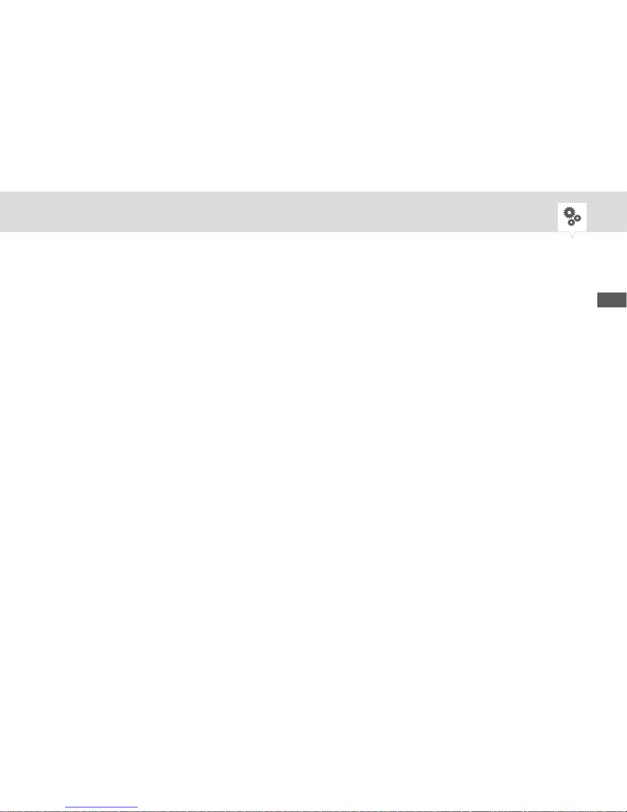
1 SELECT button
2 Boost button
3 ADV. button
4 Holiday button
5 Plus/minus buttons
6 MODE button
7 RESET button
8 Selection switch for operation, time and
programming
9 Cover
The “thermio™ eco C3” thermostat is used to regulate three heating circuits. Hot water or heating circuits can be connected and regulated independently of each other. Individual regulation of, for example,
two independent heating zones (living and sleeping areas) and hot water is implemented using three
independent switching outputs.
In the standard method, the water or room temperature is regulated by switching the device on and off
for periods of time. The on and off times for these periods can be programmed individually. In addition,
you can set a setpoint for the room temperature if the temperature regulation function is activated. An
additional frost protection function protects the device or the connected pipelines against frost when the
device is switched off.
EN
7
Page 8
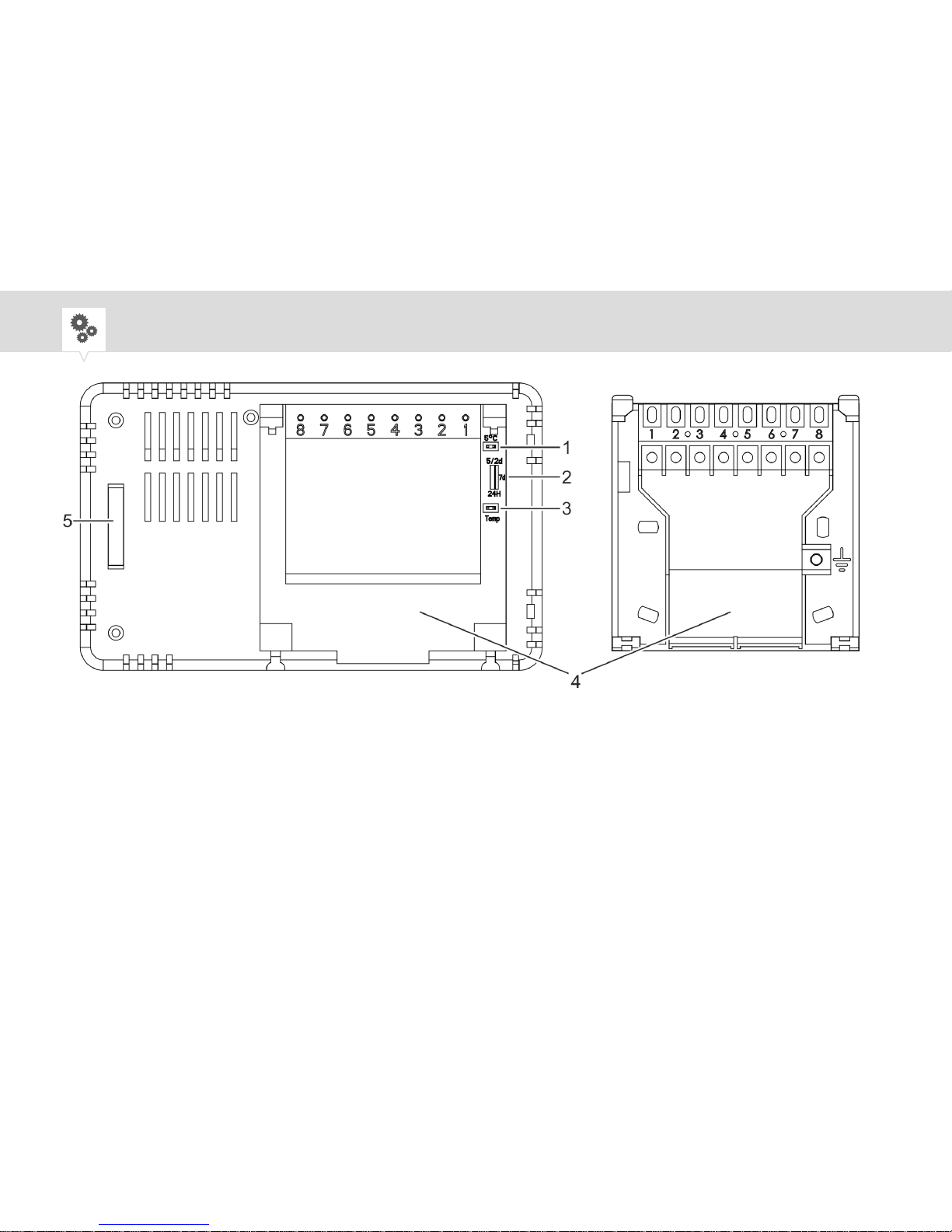
Fig. 2: Rear view (without mounting plate) and mounting plate
1 Frost protection function (jumper)
2 Programming mode
3 Temperature regulation function
(jumper)
4 Mounting plate
5 Battery compartment
8
Page 9
Temperature regulation function (for heating systems only)
If the temperature regulation function (Fig. 2/3) is activated, the device measures the room temperature
and regulates to an individually adjustable temperature setpoint Ä Chapter "Prior to operation"
on page 36.
The temperature regulation function (Fig. 2/3) and the frost protection function (Fig. 2/1) are activated
and deactivated by means of what are known as jumpers. The jumpers are included in the contents. If
the jumper is inserted in an opening, the corresponding function is activated. If the jumper is removed
from the opening, the corresponding function is deactivated.
Programming mode
To keep the water and/or room temperature at a constant level, the system is switched on and off for
periods of time. You set the desired programming mode using the switch on the back of the device
(Fig. 2/2). You can program periods of different lengths and at different intervals for each day of the
week Ä Chapter "Programming periods" on page 43.
EN
9
Page 10
24 h - Use the same programming for each day
7 d - Days are programmed independently of each other
5/2 d - Use two programs, one for weekdays (Monday to Friday) and one for the weekend (Saturday,
Sunday)
The following periods are pre-installed on delivery:
P1 On P1 Off P2 On P2 Off P3 On P3 Off
24 h 06:30 08:30 12:00 14:00 16:30 22:30
7 d 06:30 08:30 12:00 14:00 16:30 22:30
5/2 d (Mon –
Fri)
5/2 d (Sat –
Sun)
06:30 08:30 12:00 14:00 16:30 22:30
07:30 10:00 12:00 14:00 17:00 22:30
10
Page 11
On delivery, the 7 d programming for all seven days of the week is used.
The active temperature regulation function takes the programmed periods into consideration, provided
that the temperature setpoint is maintained. If the room temperature deviates from the temperature setpoint, the temperature regulation function switches on and overrides the programmed periods once for
the deviation.
Period selection
The device has a total of five different operating modes: ON, 3, 2, 1 and OFF. You can switch between
the different operating modes by pressing the SELECT button (Fig. 1/1).
Info on display Function
ON 3 2 1 OFF The device is permanently on.
ON 3 2 1 OFF The device switches 3 periods each day.
EN
11
Page 12

Info on display Function
ON 3 2 1 OFF The device switches 2 periods each day. P1 and
P3 are executed, P2 is ignored.
ON 3 2 1 OFF The device switches 1 period each day, from the
first on-period to the last off-period (P1 On – P3
Off).
ON 3 2 1 OFF The device is permanently off.
Boost function
The Boost button (Fig. 1/2) enables a short on-period lasting one to three hours. The programmed
periods are not affected.
• Boost during on-period: extends the active on-period by one to three hours
• Boost during off-period: activates a short on-period for one to three hours
12
Page 13
Pressing the Boost button once extends/activates the period for one hour.
Additional function
The ADV. button (Fig. 1/3) inverts the active period. The programmed periods are not affected.
• ADV. during on-period: switches the active period off until the next programmed on-period
• ADV. during off-period: switches the active period on ahead of schedule until the next pro-
grammed off-period
Holiday function
The Holiday button (Fig. 1/4) activates the holiday function. The device is switched off for the holiday
period set by the user Ä Chapter "Activating/deactivating the holiday function" on page 47.
Frost protection function
The frost protection (Fig. 2/1) protects the heating system water pipes connected to the device against
freezing when the device is in an off-period or has been switched off manually.
EN
13
Page 14
On delivery, the frost protection function is activated and set to a temperature of +10°C. The frost protection function can be deactivated on the rear of the device. The temperature of the frost protection
function can be set to between +5°C and +20°C Ä Chapter "Setting the frost protection temperature"
on page 39.
The frost protection function can only be set for heating systems. The device
only measures the temperature of the room in which it is installed.
Battery
In the event of a power failure, the battery provides the electricity to prevent loss of the stored date, time
and programming. When the power supply is switched back on, the stored data is retrieved and the
device continues to operate as normal.
If the device is operated on the battery for more than 30 days, the data have to be reprogrammed.
14
Page 15
Contents
The following components are included in the contents:
Number Designation
1 Thermostat thermio™ eco C3
2 Screws (3.5 x 25 mm)
2 Screws (3.5 x 20 mm)
2 Wall-plugs (5 x 25 mm)
2 Jumpers
1 Lithium battery of type 3V CR2032
EN
15
Page 16

Safety
Safety instructions
Safety instructions are indicated in this manual by symbols. The safety instructions are introduced by
signal words that express the extent of the danger.
WARNING!
This combination of symbol and signal word indicates a potentially dangerous
situation that may result in death or severe injuries if the situation is not
avoided.
NOTICE!
This combination of symbol and signal word indicates a potentially dangerous
situation that may result in material damage if the situation is not avoided.
16
Page 17
ENVIRONMENT!
This combination of symbol and signal word indicates potential dangers for
the environment.
Tips and recommendations
This symbol highlights useful tips and recommendations, as well as information for efficient and fault-free operation.
Intended use
The thermostat may only be used for timer regulation (optionally for temperature regulation) of heating
systems and hot water circuits in a temperature range from +5°C to +35°C.
Areas of application
• Boiler
• Combination boiler
EN
17
Page 18
• Domestic heating technology for heating and water heating
• Pump-controlled central heating systems
• Gravity heating systems
• The multi-channel capability enables compliance with Part L England, Part J Scotland and Part F
Northern Ireland of the building regulations for homes exceeding 150 m².
The intended use also includes compliance with all information specified in this manual.
Any use other than the intended use is considered incorrect use. The legal warranty is voided by any
interference with, or modifications to, the device.
WARNING!
Danger due to insufficient wire cross-section!
If wires with an insufficient cross-section are used, a short circuit or fire may
occur.
− Only use terminals with a cross-section between 1 mm² and 2.5 mm²
for flexible wires.
18
Page 19
Residual risks
The device is state-of-the art and designed in accordance with current safety requirements. However,
residual risks remain that require caution when using the device. The residual risks, and the conduct
and measures they require, are listed in the following.
WARNING!
Danger to life due to electric shock!
Improper assembly and installation of the device may result in life-threatening electrical voltages.
− Have assembly and connection performed by a qualified electrician only.
EN
19
Page 20
Personnel requirements
Qualified electrician
Professional training, knowledge and experience, and knowledge of the relevant standards and regulations allows the qualified electrician to perform work on electrical systems and to identify, and avoid,
potential dangers of their own accord.
A qualified electrician is specifically trained for the work environment in which they work, and are
familiar with the relevant standards and regulations.
User
The user is the person who uses and operates the device in compliance with proper use, without any
prior knowledge.
20
Page 21
Installation
Installation location
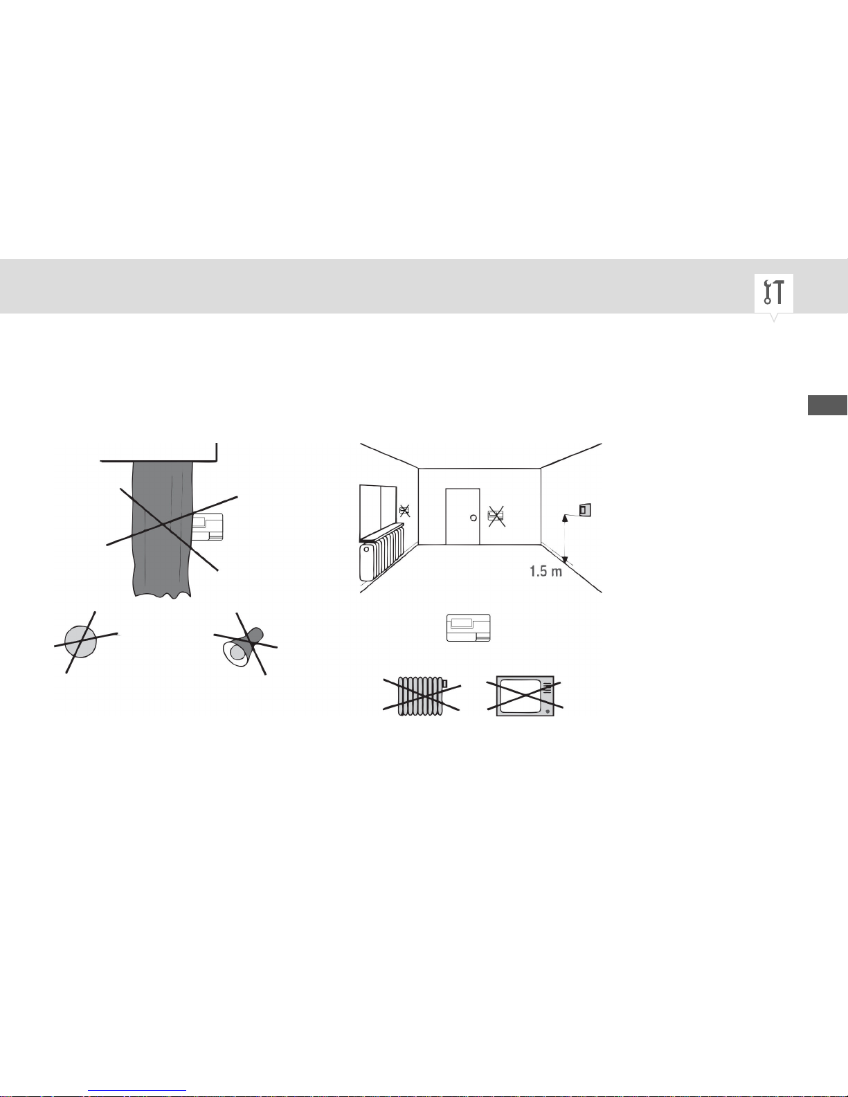
In order to ensure fault-free measurement by the room thermostat, choose the right installation location.
Fig. 3: Installation location requirements
EN
21
Page 22
On-wall mounting
The device can be mounted on the wall or in a flush-mounted socket. If installed in a flush-mounted
socket, no holes are drilled and the mounting plate is attached directly onto the flush-mounted socket
with the screws.
WARNING!
Danger to life due to electric shock!
Improper assembly and installation of the device can lead to life-threatening
electrical voltages.
− Have assembly and connection performed by a qualified electrician only.
22
Page 23
NOTICE!
Danger of material damage to the wires in the wall!
Selecting the wrong installation position can result in material damage to the
wires in the wall.
− Make sure that there are no wires in the wall at the installation position.
Personnel:
• Qualified electrician
Special tool:
• Power drill
• 5 mm drill bit
• Phillips screwdriver
Materials:
• Mounting plate
• Wall-plugs (5 x 25 mm)
• Screws (3.5 x 25 mm)
EN
23
Page 24
Prerequisite:
• The terminals for the flexible wires must have a cross-section between 1 mm² and 2.5 mm².
• If installing in a flush-mounted socket, make sure that the flush-mounted socket has been installed
correctly and is dust-free.
24
Page 25
Installing the mounting plate
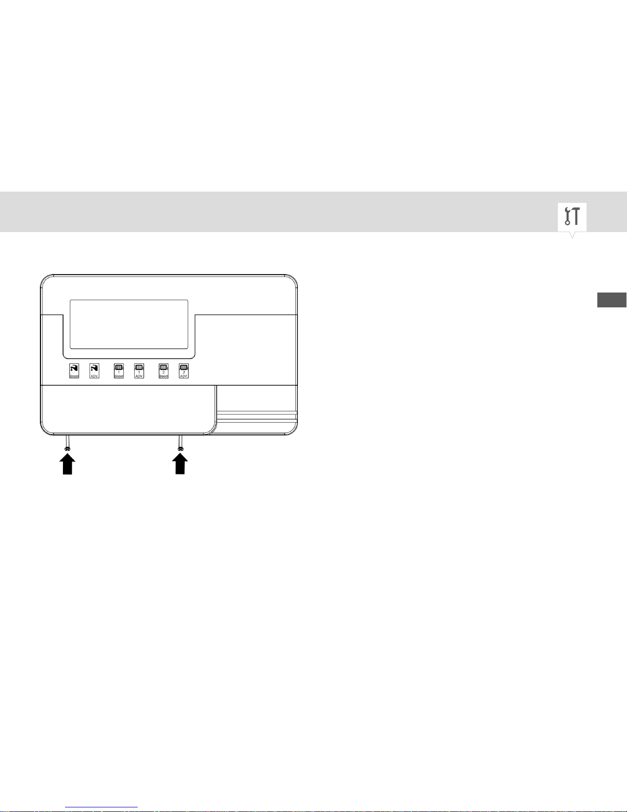
Fig. 4: Removing the mounting plate from the housing
1. Undo the screws (3.5 x 20 mm) on the housing.
EN
25
Page 26
The screws in the housing are captive, in other words you can loosen
them but you cannot remove them.
2. Remove the mounting plate.
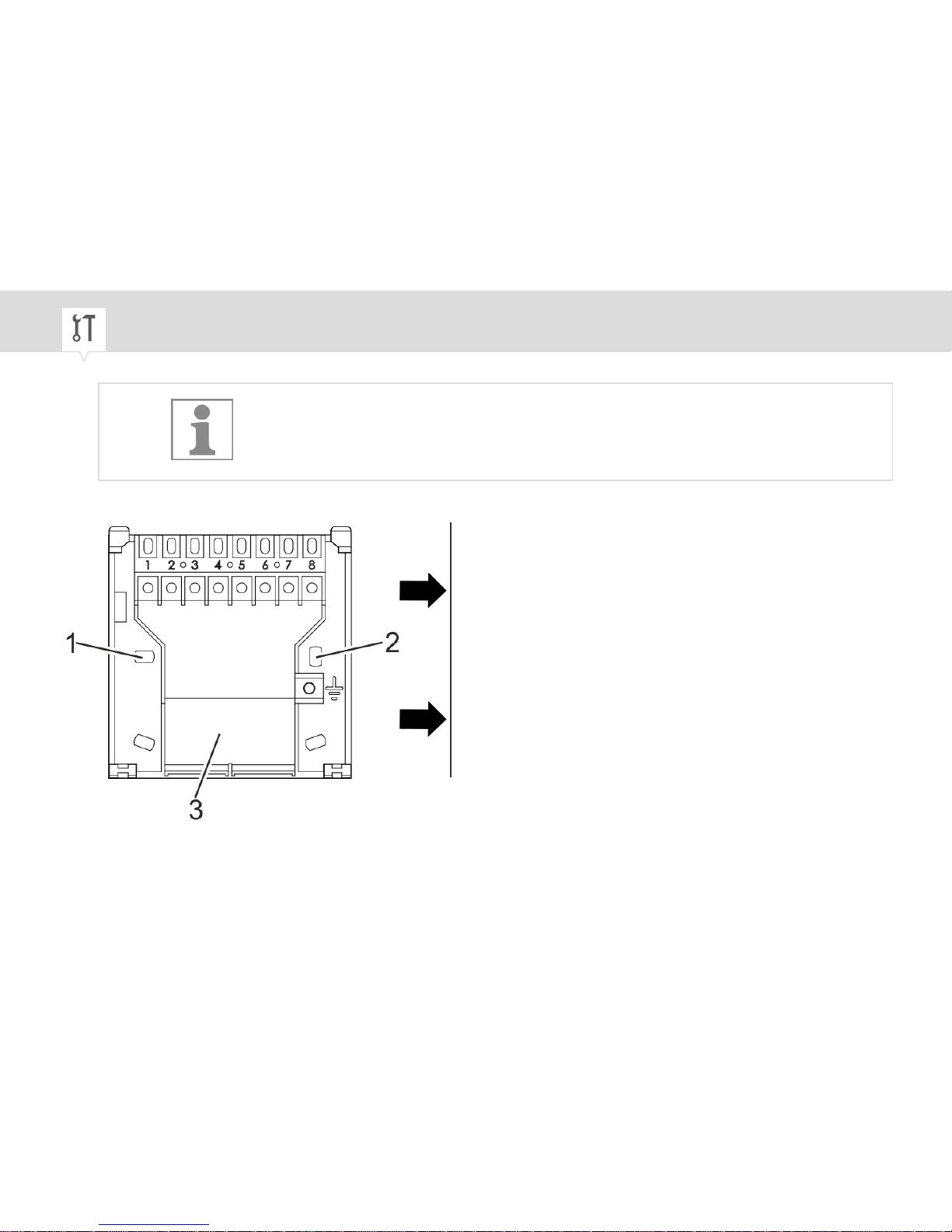
Fig. 5: Cable feed-through
26
Page 27
3. Mark the hole pattern from the mounting plate (Fig. 5/1 and 2) onto the wall.
4. Drill holes at the points you marked (5 mm diameter and at least 25 mm deep).
5. Insert the wall-plugs provided into the holes.
Electric connections
6. Strip the insulation from the connection wire.
• Stripping length: 8 mm
7. Thread the connection wire into the device through the cable feed-through (Fig. 5/3).
EN
27
Page 28
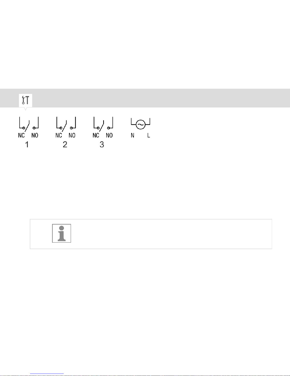
Fig. 6: Wiring diagram
1 Heating circuit 2
2 Heating circuit 1
3 Hot water
NC Normally closed contact
NO Normally open contact
N Neutral conductor
L Live conductor
8.
To ensure wiring is correct, consult the operating manual for the heating
system in use.
Insert the connection wire into the corresponding terminal in accordance with the wiring diagram
(Fig. 6).
28
Page 29
9.
NOTICE!
Tightening torques
To avoid damage and faulty contacts, tighten the terminals using a
torque of 0.6 Nm.
Tighten all terminals using the Phillips screwdriver.
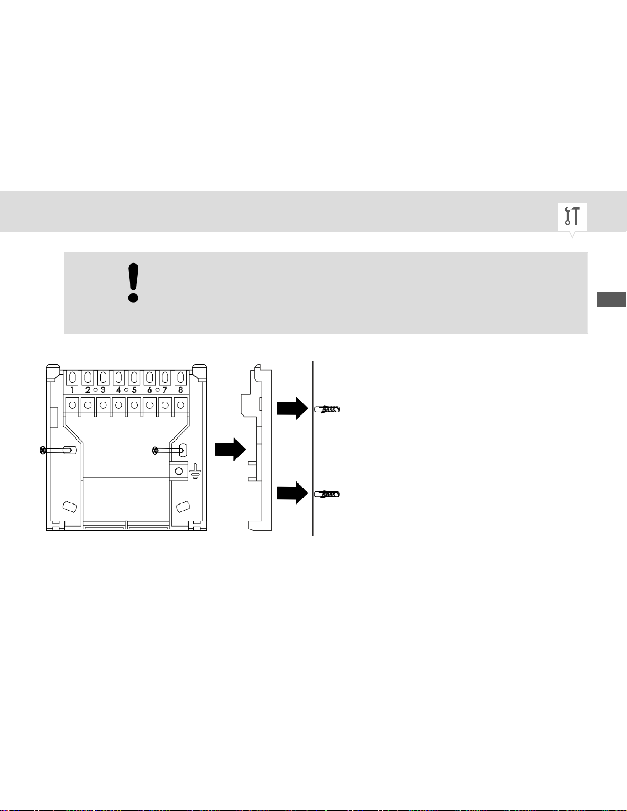
Fig. 7: On-wall mounting
10. Attach the mounting plate to the wall-plugs with screws (3.5 x 25 mm).
EN
29
Page 30
ð
The mounting plate is now installed.
30
Page 31
Inserting the battery
Handling batteries
WARNING!
Risk of injury if batteries are handled incorrectly!
Incorrect handling of batteries can result in a risk of batteries exploding or
harmful liquids escaping from the batteries.
− Never attempt to charge batteries.
− Never damage or deform batteries.
− Never short-circuit the contacts (plus and minus poles) of the batteries.
− Never use or store in locations with a potentially explosive atmosphere
or where high temperatures may occur.
− Keep batteries out of the reach of children. There is a risk of swallowing.
− Avoid skin contact with escaped liquid. In the event of accidental contact
with the skin, rinse the affected area with clear water for at least 15
minutes. Seek medical assistance immediately.
− Only use batteries of the same or equivalent type.
EN
31
Page 32

− Make sure that batteries are inserted with the correct polarity.
32
Page 33
Inserting the battery
Personnel:
• User
Special tool:
• Flat-head screwdriver
Materials:
• 1 lithium battery of type 3V CR2032
EN
33
Page 34

Fig. 8: Lifting up the battery compartment
1. On the rear of the device, carefully lift up the battery compartment with a flat-head screwdriver
(Fig. 11/1).
2. Pull the battery compartment out with your finger.
34
Page 35
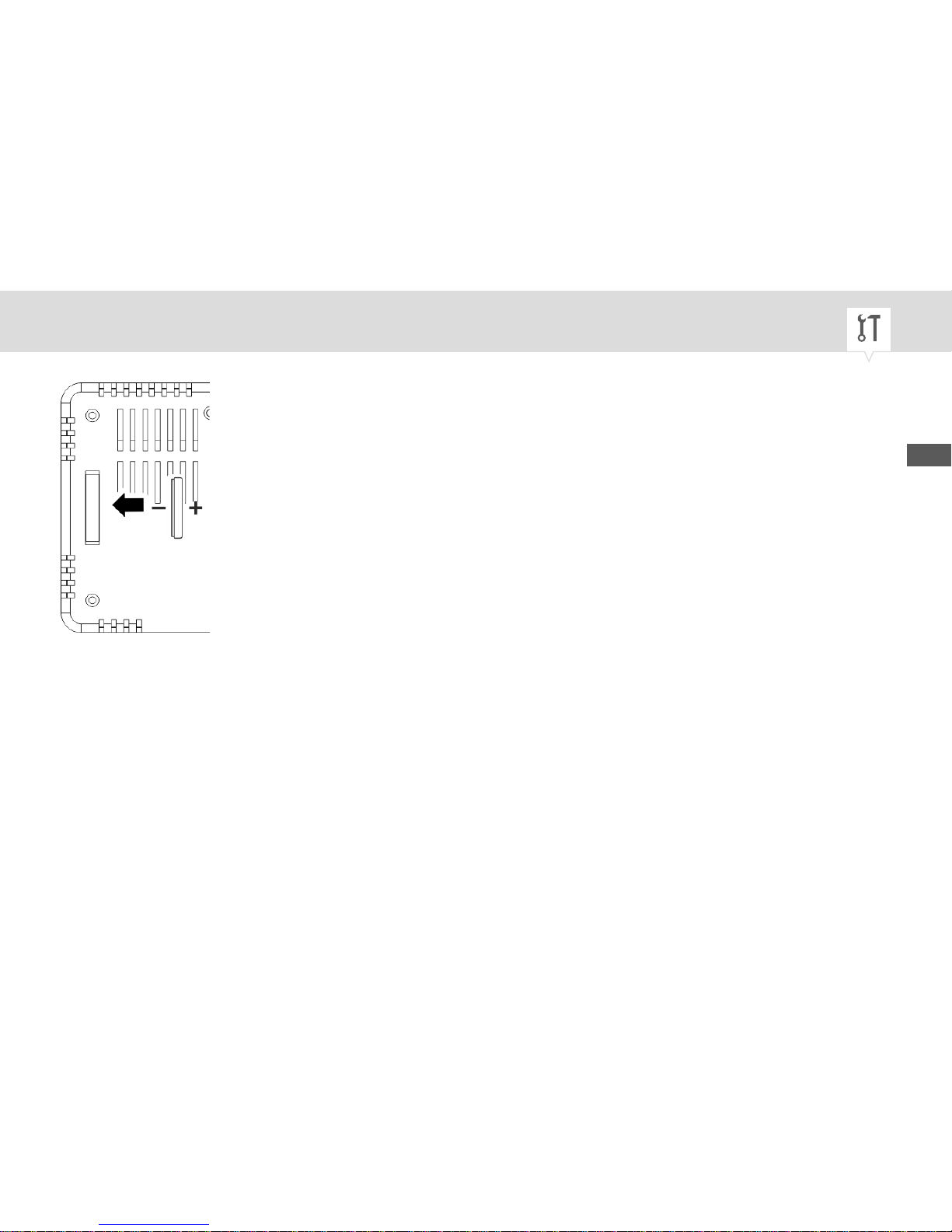
Fig. 9: Inserting the battery
3. Insert a battery with the correct polarity (Fig. 12).
4. Re-insert the battery compartment.
EN
35
Page 36
Operation
Prior to operation
Prior to operation and programming, the following three functions must be preset:
• Programming mode (Fig. 2/2)
• Frost protection function (Fig. 2/1)
• Temperature regulation function (Fig. 2/3)
On delivery, the jumpers for the frost protection function and temperature
regulation function are already inserted.
Personnel:
• User
Selecting the programming mode
1. Slide the programming mode switch (Fig. 2/2) on the rear of the device to the desired position.
36
Page 37
Personnel:
• Qualified electrician
Special tool:
• Phillips screwdriver
Materials:
• Jumper
• Screws (3.5 x 20 mm)
Deactivate frost protection (optional):
1. Remove jumper from the opening for the frost protection function (Fig. 2/1).
ð
Frost protection function is deactivated.
Deactivate frost protection (optional):
2. Remove jumper from the opening for the temperature regulation function (Fig. 2/3).
ð
Temperature regulation function is deactivated. The device now only regulates according to
the programmed times.
EN
37
Page 38
Installing the housing
NOTICE!
Danger of material damage to the wires!
When closing the housing, there is a risk of pinching wires. This results in
material damage to the wires.
− To avoid damage and faulty contacts, make sure that the wires are not
pinched when the you close the housing.
3. Place the housing on the mounting plate.
4. Attach the housing to the mounting plate with screws (3.5 x 20 mm).
ð
The device is now fully installed.
Activating the settings
5.
Do not use a pencil or similarly fragile object to press the RESET
button.
Use a thin, non-metallic blunt object to press the RESET button.
38
Page 39
ð
The device starts automatically.
You have to reset the device with the RESET button each time you remove
or insert a jumper.
Depending on which jumpers are inserted, the frost protection temperature and the temperature of the
temperature regulation function are set. For example, if the frost protection function is activated (jumper
inserted) and the temperature regulation function is deactivated (jumper removed), only the temperature
of the frost protection function is displayed for setting. If, however, both functions are activated (as they
are on delivery), both temperatures are displayed for setting.
Setting the frost protection temperature
Personnel:
• User
Prerequisite:
EN
39
Page 40
• Selection switch (Fig. 1/8) is set to RUN.
• A jumper is inserted in the opening for the frost protection function (Fig. 2/1).
1. Open the cover and fold it down.
2. Press , and multiple times in succession until all the circuits are set to
OFF.
3. Press and hold simultaneously for at least five seconds.
4. Set the desired frost protection temperature using
.
5. Press to save the frost protection temperature.
Setting the temperature setpoint
Personnel:
• User
Prerequisite:
40
Page 41
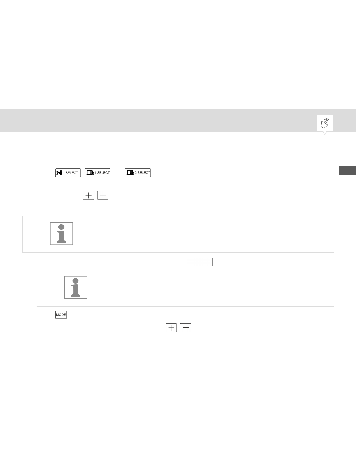
• Cover is open.
• A jumper is inserted in the opening for the temperature regulation function (Fig. 2/3).
1. Press , and multiples times in succession until one of the operating
modes ON, 1, 2 or 3 is selected.
2. Press and hold simultaneously for at least five seconds.
ð
The temperature flashes on the display.
If the frost protection function is active (jumper inserted), the temperature for
the frost protection function is set first, followed by the temperature setpoint.
3. Set the desired frost protection temperature using .
The frost protection temperature can be set to between +5°C and
+20°C.
4. Press to save the frost protection temperature.
5. Set the desired temperature setpoint using
.
EN
41
Page 42
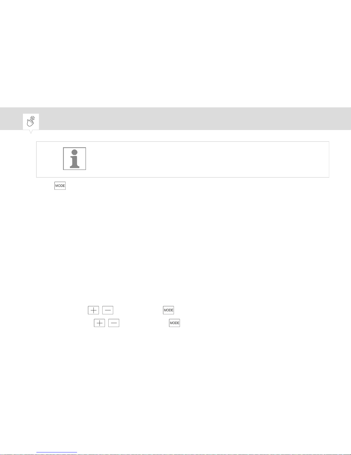
The temperature setpoint can be set to between +5°C and +35°C.
6. Press to save the temperature setpoint.
Setting the date/time
For the device to execute the programming correctly, you first have to set the date and time.
Personnel:
• User
Prerequisite:
• Cover is open.
1. Slide the selection switch (Fig. 1/8) to
CLOCK SET.
ð
The display turns on.
2. Set the year with
and save it with .
3. Set the month with and save it with .
42
Page 43
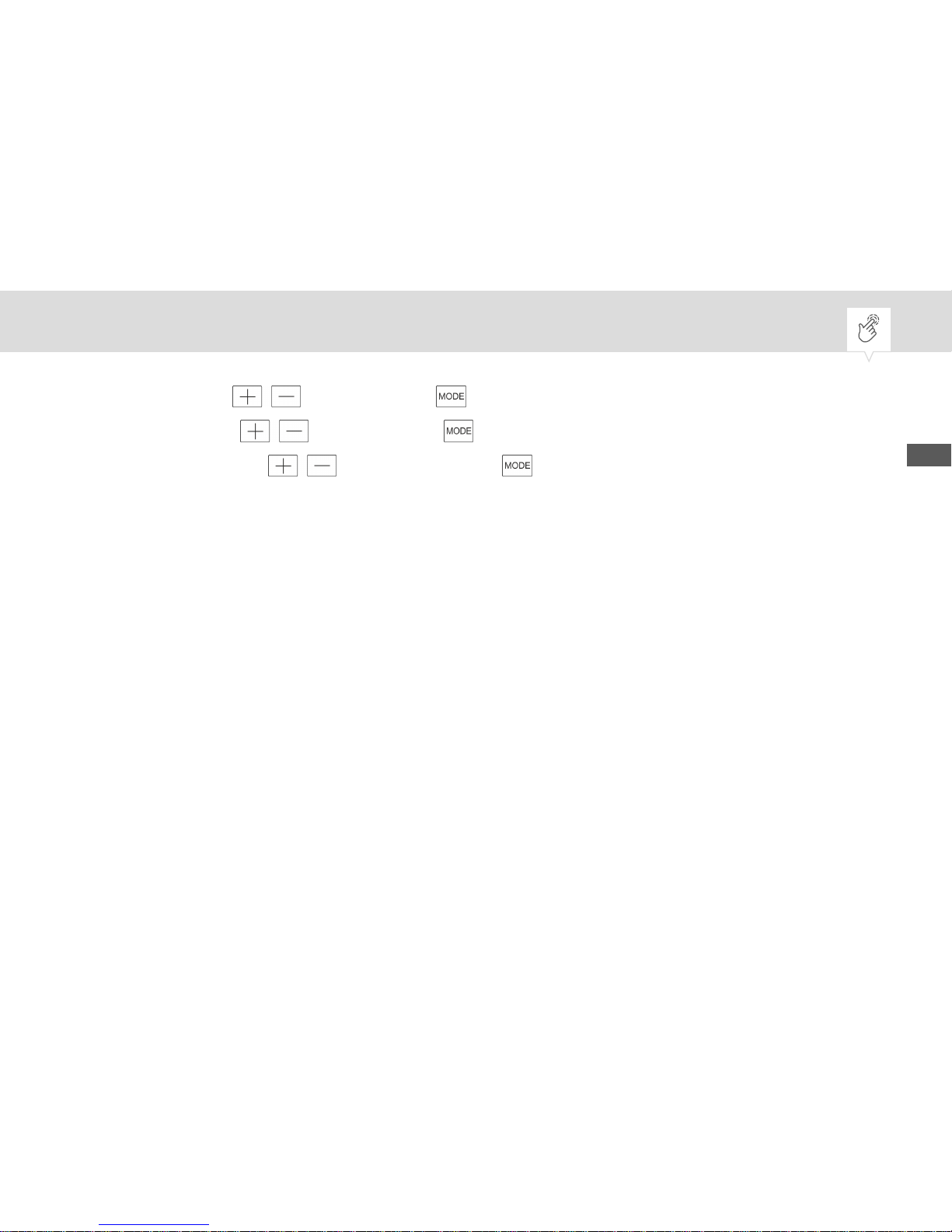
4. Set the day with and save it with .
5. Set the hour with and save it with .
6. Set the minutes with and save them with .
ð
The date and time are now set.
7. Slide the selection switch (Fig. 1/8) to RUN to operate the device or slide it to PROG SET to program the device.
Programming periods
To keep the water and room temperature at a constant level, the system is switched on and off for
periods of time. There are a total of three periods available for each day, and each can be programmed
individually. You specify the switch-on time and switch-off time for each period.
Personnel:
• User
Prerequisite:
• Cover is open.
1. Slide the selection switch (Fig. 1/8) to PROG SET.
EN
43
Page 44
ð
The display turns on.
Periods for water temperature
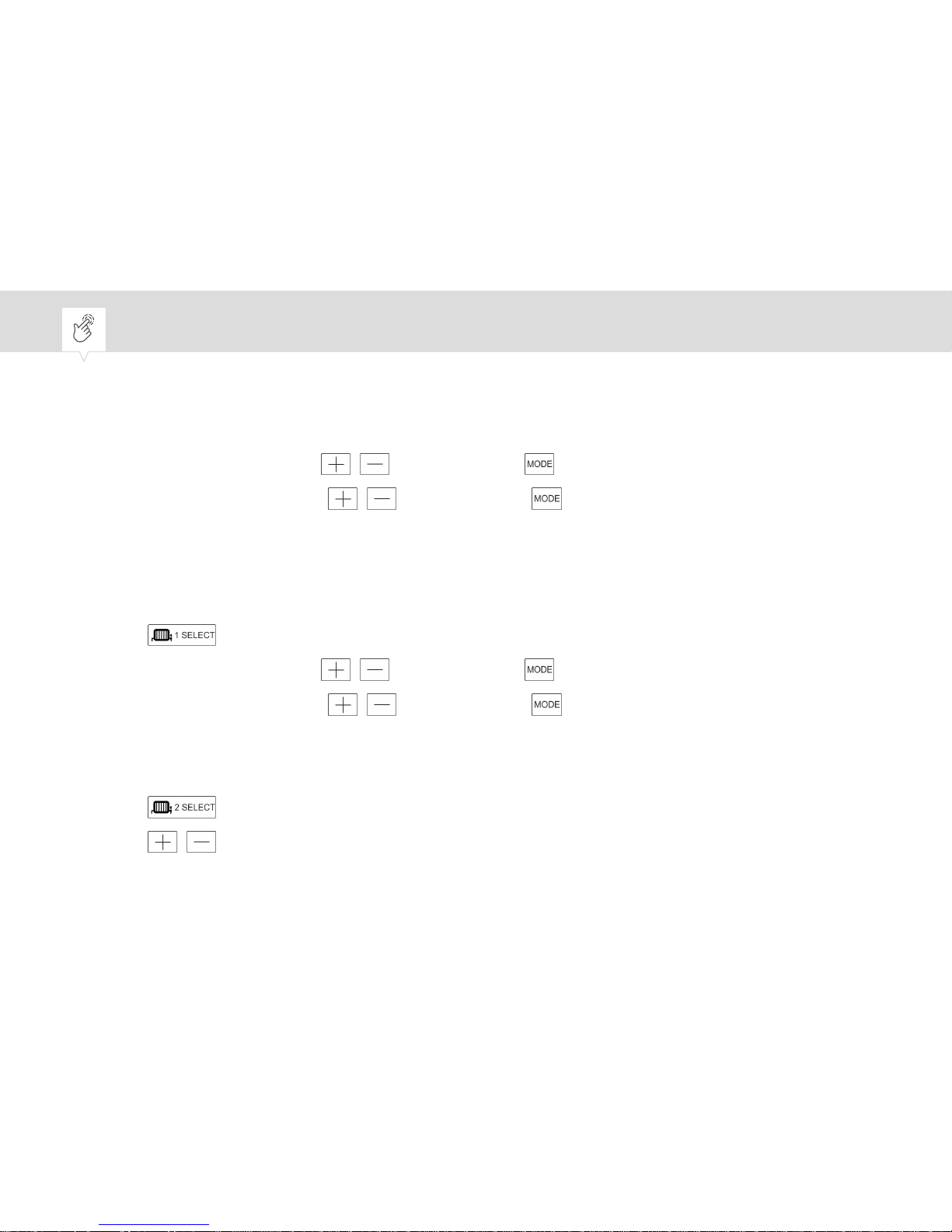
2. Set the time for P1 ON with and save it with .
3. Set the time for P1 OFF with and save it with .
4. Repeat steps 2 and 3 for the following two periods.
ð
Three periods are programmed for regulating the water temperature.
Periods for heating circuit
5. Press to program periods for the first heating circuit.
6. Set the time for P1 ON with and save it with .
7. Set the time for P1 OFF with and save it with .
8. Repeat steps 6 and 7 for the following two periods.
ð
Three periods are programmed for regulating the first heating circuit.
9. Press
to program periods for the second heating circuit.
10. Press
to set the desired times for the periods.
ð
Three periods are programmed for regulating the second heating circuit.
44
Page 45
Checking the programming
11. Press the SELECT button for the relevant circuit.
ð
The periods for the relevant circuit are shown on the display.
12. Press to check the next period.
13. Slide the selection switch (Fig. 1/8) to RUN.
ð
The device regulates according to the times entered.
If the temperature regulation function is active, the device regulates according to the temperature setpoint set by the user. If the
room temperature deviates from the temperature setpoint, the
temperature regulation function switches on and overrides the
programmed periods once for the deviation.
EN
45
Page 46
Selecting the operating mode
Personnel:
• User
Prerequisite:
• Cover is open.
1. Press the SELECT button for the circuit in question multiple times until the desired operating
mode is selected on the display.
Press the SELECT button once to switch to the next operating mode,
e.g.:
In operating mode ON 1 2 3 OFF ð press the SELECT button twice to
activate operating mode ON 1 2 3 OFF
.
ð The device regulates according to the selected operating mode
Ä "Period selection"
on page 11
.
46
Page 47
Activating/deactivating the holiday function
Personnel:
• User
Prerequisite:
• Cover is open.
• Selection switch (Fig. 1/8) is set to RUN.
1. Press .
2. Set the length of the holiday with
and save it with .
ð
The device is switched off for the specified period.
Selecting the background lighting
There are two setting options for the background lighting.
AUTO - Background lighting automatically switches on for ten seconds when any button is pressed.
ON - The background lighting is on permanently.
EN
47
Page 48
Personnel:
• User
Prerequisite:
• Cover is open.
• Selection switch (Fig. 1/8) is set to RUN.
1. Press and hold for five seconds.
2. Press to select the setting option.
3. Press .
ð
The selected background lighting is now activated.
48
Page 49
Replacing the battery
Handling batteries
WARNING!
Risk of injury if batteries are handled incorrectly!
Incorrect handling of batteries can result in a risk of batteries exploding or
harmful liquids escaping from the batteries.
− Never attempt to charge batteries.
− Never damage or deform batteries.
− Never short-circuit the contacts (plus and minus poles) of the batteries.
− Never use or store in locations with a potentially explosive atmosphere
or where high temperatures may occur.
− Keep batteries out of the reach of children. There is a risk of swallowing.
− Avoid skin contact with escaped liquid. In the event of accidental contact
with the skin, rinse the affected area with clear water for at least 15
minutes. Seek medical assistance immediately.
− Only use batteries of the same or equivalent type.
EN
49
Page 50
− Make sure that batteries are inserted with the correct polarity.
Replacing the battery
If the batteries are flat, the battery symbol appears on the display.
• Replace the batteries as soon as they are flat or after a longer period of non-use.
• When you replace the batteries, the data is temporarily stored for 10 minutes by gold foil capacitors.
50
Page 51
Personnel:
• User
Special tool:
• Flat-head screwdriver
Materials:
• 1 lithium battery of type 3V CR2032
EN
51
Page 52
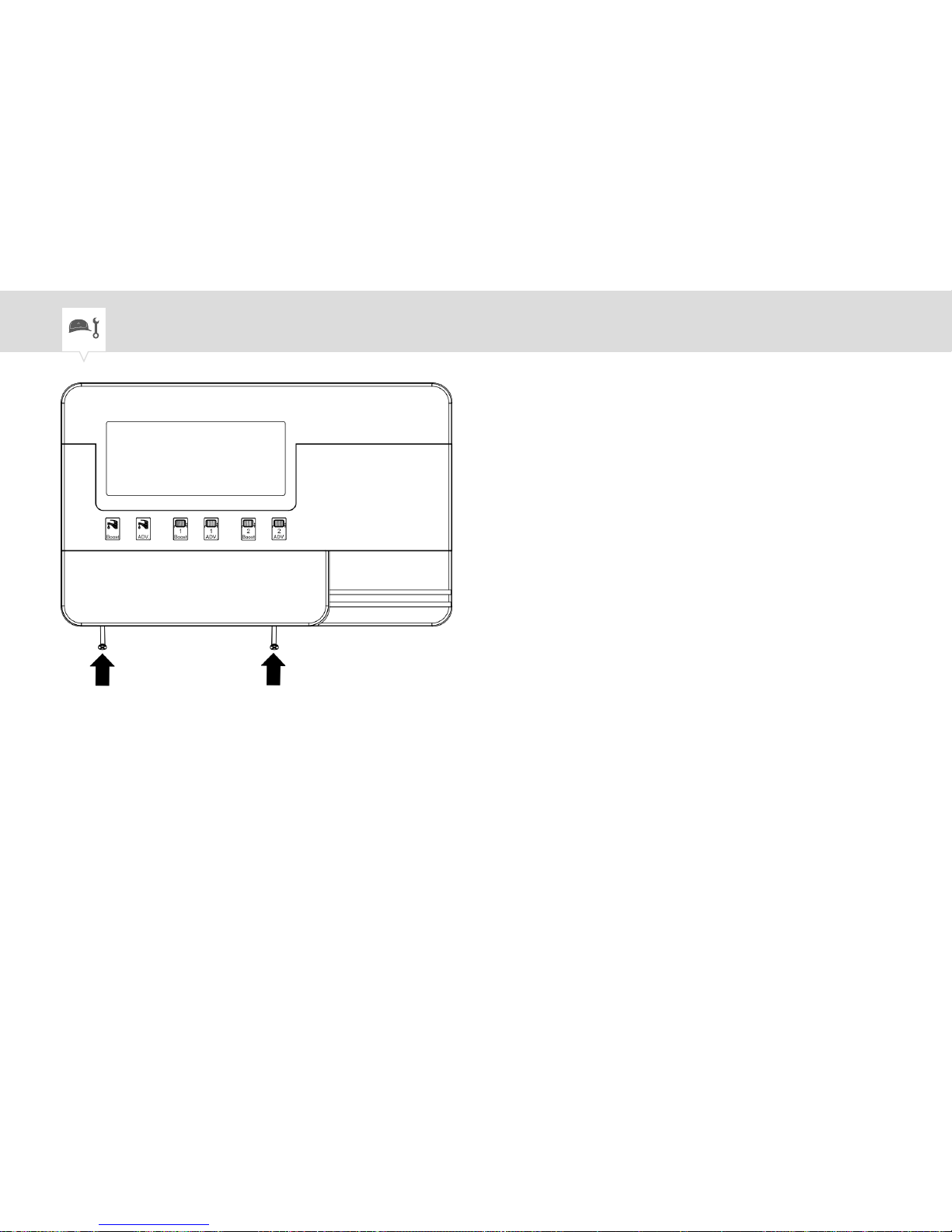
Fig. 10: Removing the housing from the mounting plate
1. Undo the screws on the housing.
2. Remove the housing from the mounting plate.
52
Page 53
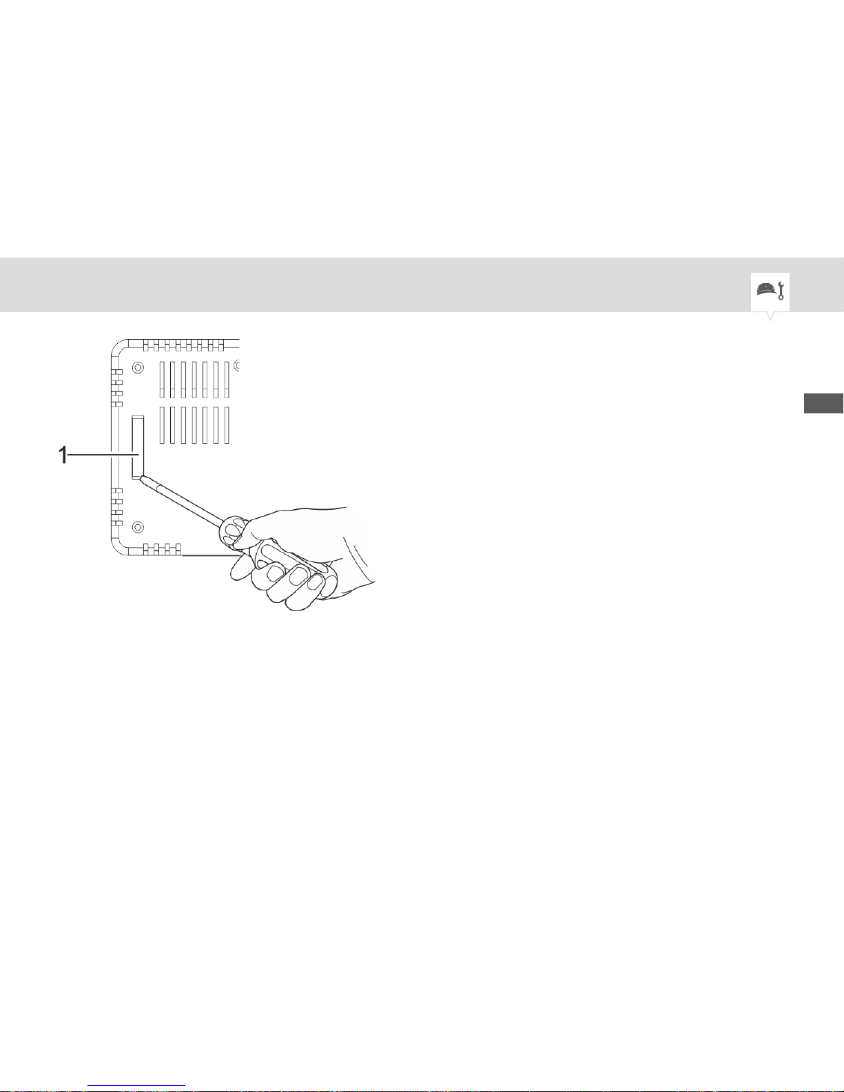
Fig. 11: Lifting up the battery compartment
3. On the rear of the device, carefully lift up the battery compartment with a flat-head screwdriver
(Fig. 11/1).
4. Pull the battery compartment out with your finger.
5. Remove used batteries and dispose of correctly.
EN
53
Page 54
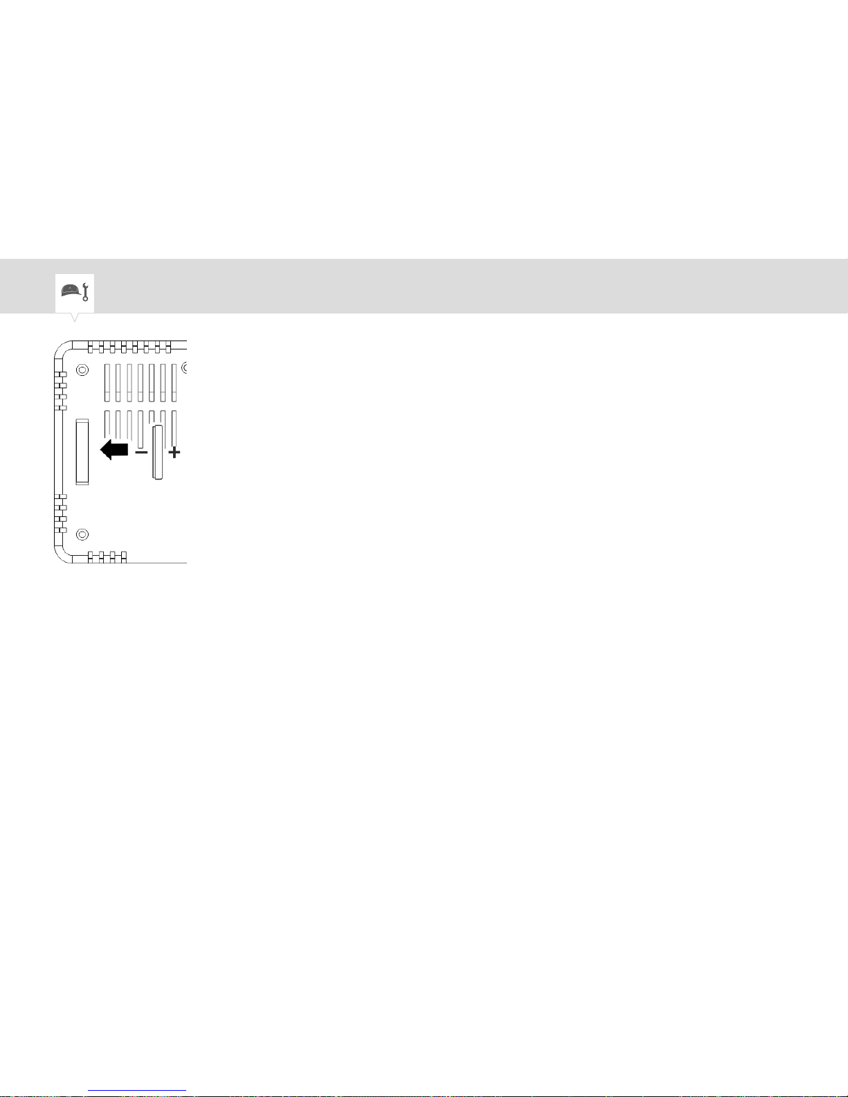
Fig. 12: Replacing the battery
6. Insert a new battery with the correct polarity (Fig. 12).
7. Re-insert the battery compartment.
8. Place the housing on the mounting plate and screw it on tight.
54
Page 55
Disposal
Improper disposal
ENVIRONMENT!
Incorrect disposal presents an environmental danger.
Incorrect disposal could result in environmental dangers.
− Electric scrap and electronic components must be disposed of correctly,
i.e. the parts for disposal must be sorted into material groups.
− Batteries/rechargeable batteries (Directive 2006/66/EC) and electrical or
electronic scrap must under no circumstances be disposed of with general waste. If in doubt, please obtain information about environmentally
responsible disposal from specialist disposal companies.
− Disposal must be environmentally responsible and must comply with the
current status of environmental protection, recycling and disposal technology.
EN
55
Page 56

Recycling
If no agreement has been made covering return or disposal, ensure that the dismantled components are
recycled:
• Scrap metals.
• Ensure plastic elements are recycled.
• Dispose of other components after sorting them according to material properties.
56
Page 57
Technical data
Electrical data
Supply voltage AC 230 V ±10% 50 – 60 Hz
Battery replacement time (power reserve) > 30 days (programs saved in EEPROM)
Switching output Changeover contact, potential-free
Switching capacity – resistive load 3 A/ 250 V AC
Switching capacity – inductive load cos. phi 0.6 1 A/ 250 V AC
Accuracy ±1 second/day at 20°C
Battery CR2032
Control function Heating
Control type Two-point (ON/OFF)
Hysteresis ±0.5 K / ±1 K
123
%
456
α
789
λ
123
Ω
EN
57
Page 58

Electrical data
Control range +10°C (frost protection +5°C to +20°C)
+5°C to +35°C
Control accuracy ±0.5°C
Sensor (thermistor) 100 K (at 25°C) NTC
Rated impulse voltage strength (Uimp) 4 kV
Electrical connection
Device Screw terminals with wire protection, max.
2.5 mm²
123
%
456
α
789
λ
123
Ω
58
Page 59
Operating data
Operating mode RUN/AUTO
Manual switch Boost time
Channels 3
Programs 7 days
5/2 days
1 – 7 days
Advance
Boost
Holiday program
Individual programming (max. 3 ON/OFF
switching times)
123
%
456
α
789
λ
123
Ω
EN
59
Page 60

Operating data
Daily program (ON/OFF)
Weekly program (ON/OFF)
Display and format
Resolution Room temperature: 0.1°C
Temperature setpoint: 1°C
Time of day: 1 minute
Display lighting Light blue
Time display format 12 h format (AM/PM)
24 h format
Shortest switching time Boost: 1, 2, 3 hours
123
%
456
α
789
λ
123
Ω
60
Page 61
Display and format
ON/OFF: 10 minutes
Programming time: 10 minutes
Room temperature display +10°C to +50°C
Summer/winter time Automatic summer/winter clock change
Time Digital
Status display Operating mode
Status display for heating (lamp)
Ambient conditions
Humidity (in operation) 10% to 90% relative humidity, condensation-free
Humidity (storage) 10% to 90% relative humidity, condensation-free
123
%
456
α
789
λ
123
Ω
EN
61
Page 62

Ambient conditions
Temperature (in operation) +0°C to +50°C
Temperature (storage) -20°C to +50°C
General data
Colour White/grey
Weight 330 g
Material ABS plastic
Size 125 x 89 x 35 mm
Installation Wall-mounted or flush-mounted socket
123
%
456
α
789
λ
123
Ω
62
Page 63
Compliance with standards
ErP class I
ErP function ON/OFF room thermostat
ErP description Room thermostat that regulates the on/off state of
a heating device
ErP contribution to seasonal space heating energy
efficiency
1%
IP code IP20
Protection class II, when installed accordingly
Certification mark CE
Energy Saving Trust
123
%
456
α
789
λ
123
Ω
EN
63
Page 64

Compliance with standards
Pollution degree 2
Standards and directives Mode of operation and additional properties: Type
1.B
123
%
456
α
789
λ
123
Ω
64
Page 65
EN
65
Page 66

66
Page 67
EN
67
Page 68

80.10.1495.7/0217/V01
Grässlin GmbH
Bundesstrasse 36
78112 St. Georgen
GERMANY
Telephone: +49 7724 933-0
Fax: +49 7724 933-240
Email: [email protected]
Internet: www.graesslin.de
 Loading...