

Page 1
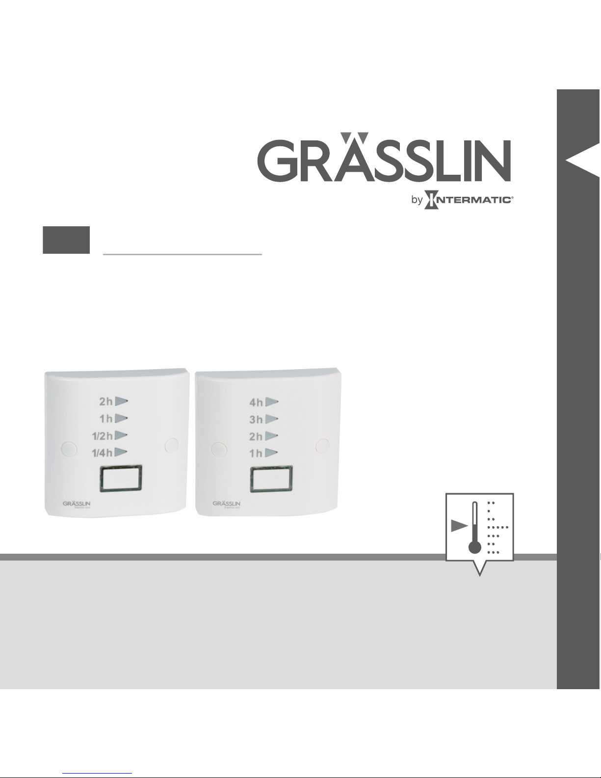
thermio™ eco B2B/B4B
EN
Operating manual
Page 2
This manual ensures safe and efficient use of the
“thermio™ eco B2B” or “thermio™ eco B2B B4B”
countdown timer (referred to as “device” in the following). This manual is a component of the device and
must remain accessible at all times for everyone who
uses the device.
2
Page 3
Everyone who uses the device must have read and
understood this manual before commencing any work.
The basic prerequisite for working safely is compliance
with all safety instructions and usage instructions specified in this manual. Furthermore, the local accident prevention regulations and the general safety regulations in
the area in which the device is operated apply.
Copyright
This manual is copyright protected.
EN
3
Page 4

Handover of this manual to third parties, reproductions of
any type and form – including excerpts – and use and/or
disclosure of the content without the written permission
of Grässlin GmbH (referred to as “manufacturer” in the
following), except for internal purposes, is not permitted.
Violations will result in liability for compensation. The
manufacturer reserves the right to assert additional
claims.
The copyright is held by the manufacturer.
© Grässlin GmbH
Bundesstr. 36
78112 St. Georgen
GERMANY
4
Page 5
Declaration of conformity and download instructions
The declaration of conformity for the device described in
this manual, a download of this manual, and the technical data can be found at
www.graesslin.de
.
EN
5
Page 6
Overview................................................ 7
Safety................................................... 11
Installation............................................ 21
Operation............................................. 28
Disposal............................................... 32
6
Page 7
Overview
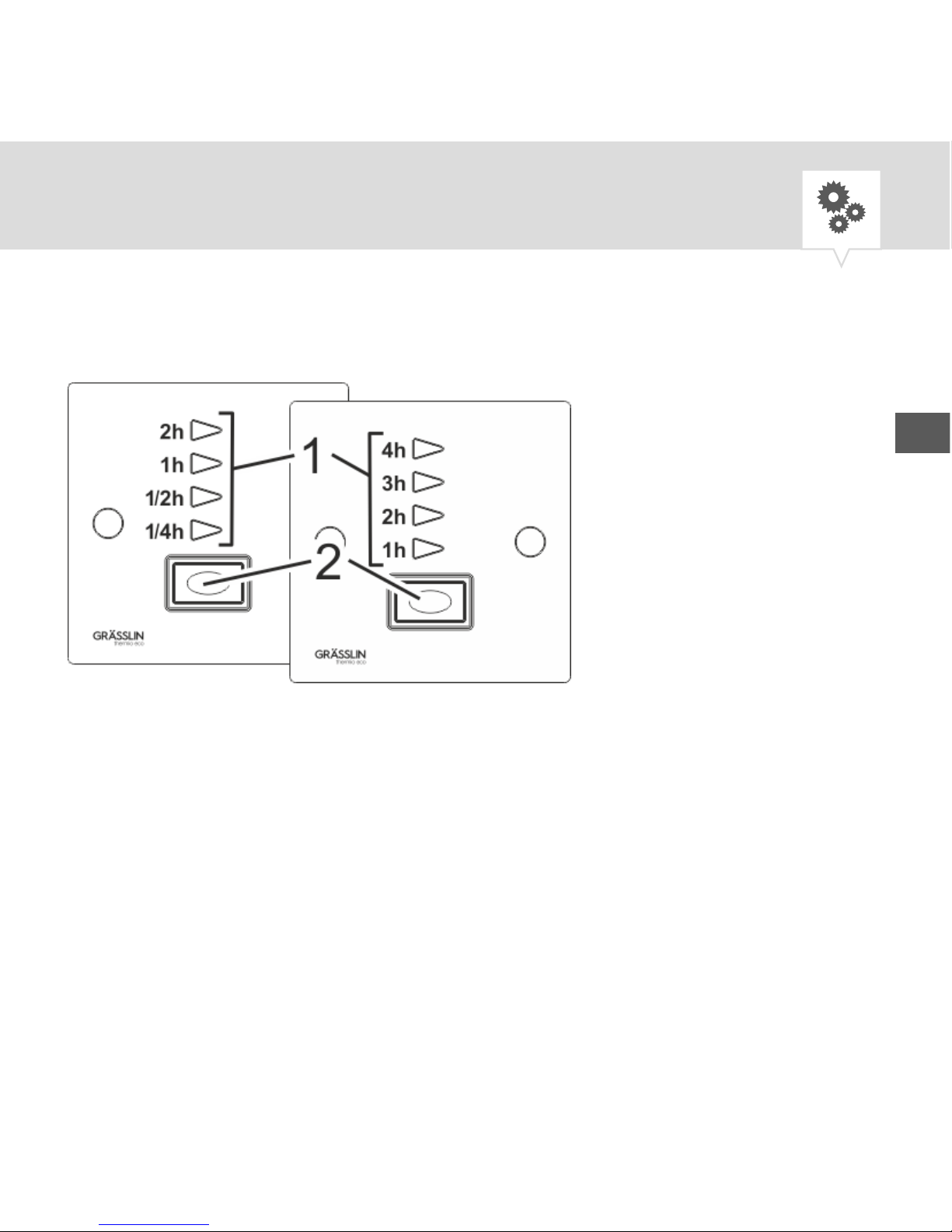
Fig. 1: Overview of “thermio™ eco B2B” (left) and
“thermio™ eco B4B” (right)
1 LEDs for time intervals
2
[Boost]
button
EN
7
Page 8
Description of function
“thermio™ eco B2B” and “thermio™ eco B4B” are
countdown timers with selectable, predefined periods.
The connected devices are supplied with electricity
during the set periods. When the period ends, the connected device is switched off.
The set periods are displayed by LEDs (Fig. 1/1) and can
be selected using the
[Boost]
button.
Adjustable periods
• “thermio™ eco B2B” countdown timer
− 1/4 h (15 min), 1/2 h (30 min), 1 h and 2 h
• “thermio™ eco B4B” countdown timer
− 1 h, 2 h , 3 h and 4 h
8
Page 9
Elements Function
LEDs Display the selected period that is cur-
rently counting down
[Boost]
button
Select and activate the period
EN
9
Page 10
The following components are included in the contents:
Number Designation
1 Countdown timer “thermio™ eco B2B”
or “thermio™ eco B4B”
2 3.5 mm screws
1 Strain relief clamps
2 Screw covers
1 Screw terminal (optional)
10
Page 11

Safety
Safety instructions
Safety instructions are indicated in this manual by symbols. The safety instructions are introduced by signal
words that express the extent of the danger.
WARNING!
This combination of symbol and signal word
indicates a potentially dangerous situation that
may result in death or severe injuries if the situation is not avoided.
EN
11
Page 12
NOTICE!
This combination of symbol and signal word
indicates a potentially dangerous situation that
may result in material damage if the situation
is not avoided.
ENVIRONMENT!
This combination of symbol and signal word
indicates potential dangers for the environment.
12
Page 13
Tips and recommendations
This symbol highlights useful tips and recommendations, as well as information for efficient
and fault-free operation.
Intended use
“thermio™ eco B2B” and “thermio™ eco B4B” are
countdown timers with selectable, predefined periods for
supplying power to connected devices in private and
commercial areas. The connected devices must comply
with the limits specified in the technical data.
EN
13
Page 14
Areas of application:
• Electric radiators and heating elements
• Oil radiators
• Electric towel rails
• Heating systems
• Hotplates
• Fan heaters
• Lighting (not discharge lamps)
The intended use also includes compliance with all information specified in this manual.
Any use other than the intended use is considered incorrect use.
14
Page 15
Wire cross-section
WARNING!
Danger due to insufficient wire cross-section!
If wires with an insufficiently large cross-section are used, short circuits or fires may occur.
− Only use terminals with a cross-section
between 1 mm² and 2.5 mm² for flexible
wires.
EN
15
Page 16
WARNING!
Risk of injury due to uncontrolled behaviour of connected loads!
− Before starting the device, check whether
the connected load could cause hazardous situations for persons.
NOTICE!
Damage to the device due to unsuitable
installation location!
Installation at an unsuitable location can cause
damage to the device.
16
Page 17
− Only use the device in dry rooms and do
not install close to devices with inductive
discharge (motors, transformers, etc.).
Residual risks
The device is state-of-the art and designed in accordance with current safety requirements. However, residual
risks remain that require caution when using the device.
The residual risks, and the conduct and measures they
require, are listed in the following.
EN
17
Page 18
WARNING!
Danger to life due to electric shock!
Improper assembly and installation of the
device can lead to life-threatening electrical
voltages.
− Have assembly and connection performed
by a qualified electrician only.
18
Page 19
Personnel requirements
Qualified electrician
Professional training, knowledge and experience, and
knowledge of the relevant standards and regulations
allows the qualified electrician to perform work on electrical systems and to identify, and avoid, potential dangers of their own accord.
A qualified electrician is specifically trained for the work
environment in which they work, and are familiar with
the relevant standards and regulations.
EN
19
Page 20
User
The user is the person who uses and operates the device
in compliance with proper use, without any prior knowledge.
20
Page 21
Installation
Electric connection and installation
The device is installed on a flush-mounted socket (BS
4662 or BS 5733). The connection wire is either routed
out of the flush-mounted socket or it is routed to the
device on the wall.
In general, the following instructions apply to
both installation types. Where there are difference, the corresponding installation type is
specified before the instructions.
EN
21
Page 22
WARNING!
Danger to life due to electric shock!
Improper assembly and installation of the
device can lead to life-threatening electrical
voltages.
− Have assembly and connection performed
by a qualified electrician only.
Personnel:
• Qualified electrician
Special tool:
• Flat-head screwdriver
Materials:
22
Page 23
• 3.5 mm screws
Prerequisite:
• The terminals for the flexible wires must have a
cross-section between 1 mm² and 2.5 mm².
• Make sure that the flush-mounted socket has been
installed correctly and is dust-free.
1. On-wall connection wires: Undo the strain relief
screws (Fig. 2/4) on the rear of the device and place
to one side.
2. Remove the plastic cover.
3. Strip the insulation from the connection wire.
• Stripping length: 8 mm
EN
23
Page 24
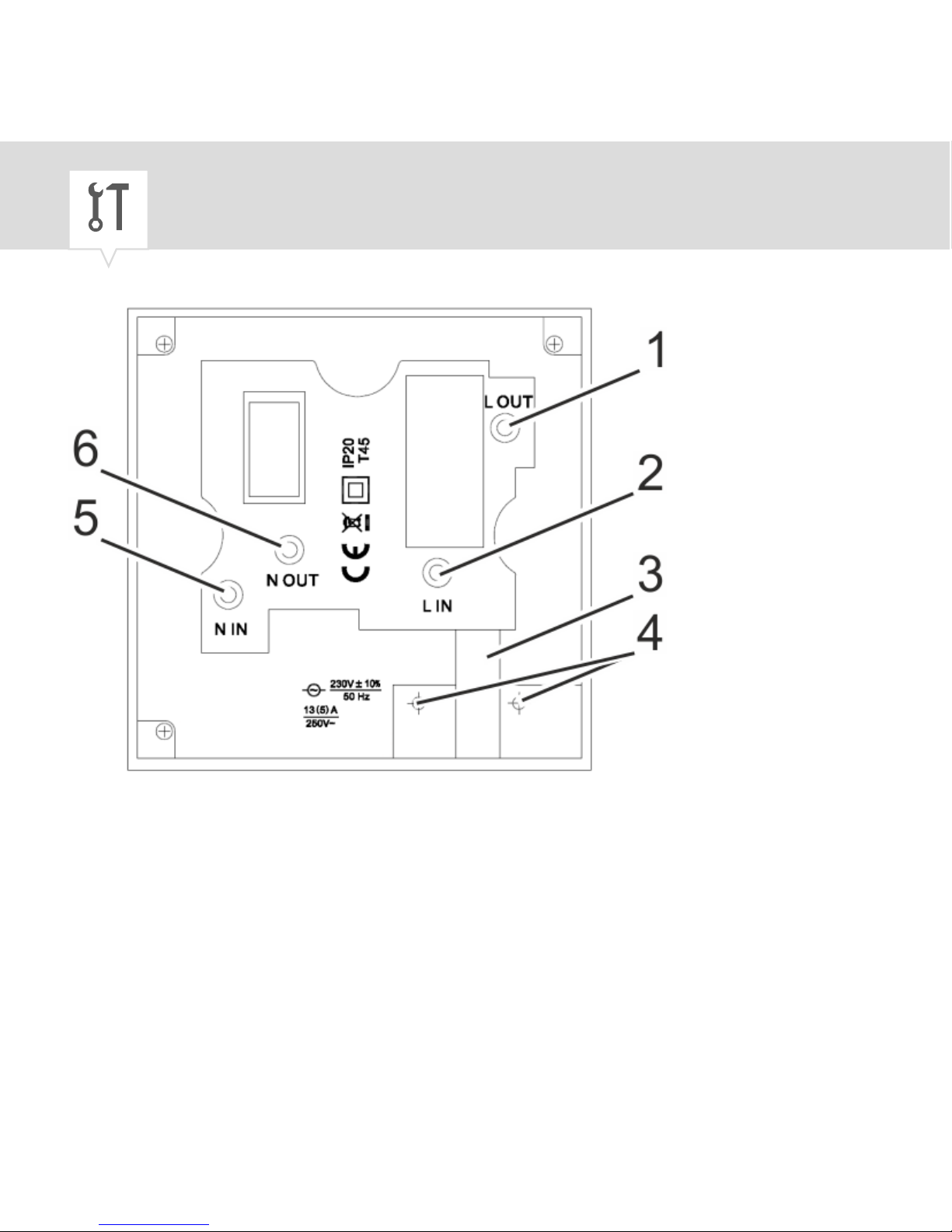
Fig. 2: Wiring diagram
24
Page 25
1 Switchable live wire (OUT)
2 Live wire (IN)
3 Cable feed-through
4 Screws for strain relief clamp
5 Neutral (IN)
6 Neutral (OUT)
4. Insert the connection wires into the corresponding
terminals in accordance with the wiring diagram
(Fig. 2).
EN
25
Page 26
5.
NOTICE!
Tightening torques
To avoid damage and faulty contacts,
tighten the terminals using a torque of
0.6 Nm.
Tighten all the terminals.
6. On-wall connection wires: Thread the connection
wires into the device through the cable feed-through
(Fig. 2/3).
7. On-wall connection wires: Tighten the strain relief
clamp from the contents using the screws for the
strain relief clamp (Fig. 2/4).
26
Page 27
NOTICE!
Danger of material damage to the wires!
When screwing the device tight, there is a risk
of pinching wires. This results in material
damage to the wires.
− To avoid damage and faulty contacts,
make sure that the wires are not pinched
when you insert the device into the flushmounted socket.
8. Fasten the device onto the flush-mounted socket
using the screws (3.5 mm).
9. Insert the screw covers.
EN
27
Page 28
Operation
You can use the
[Boost]
button to select a period in
which the connected loads are switched on.
Personnel:
• User
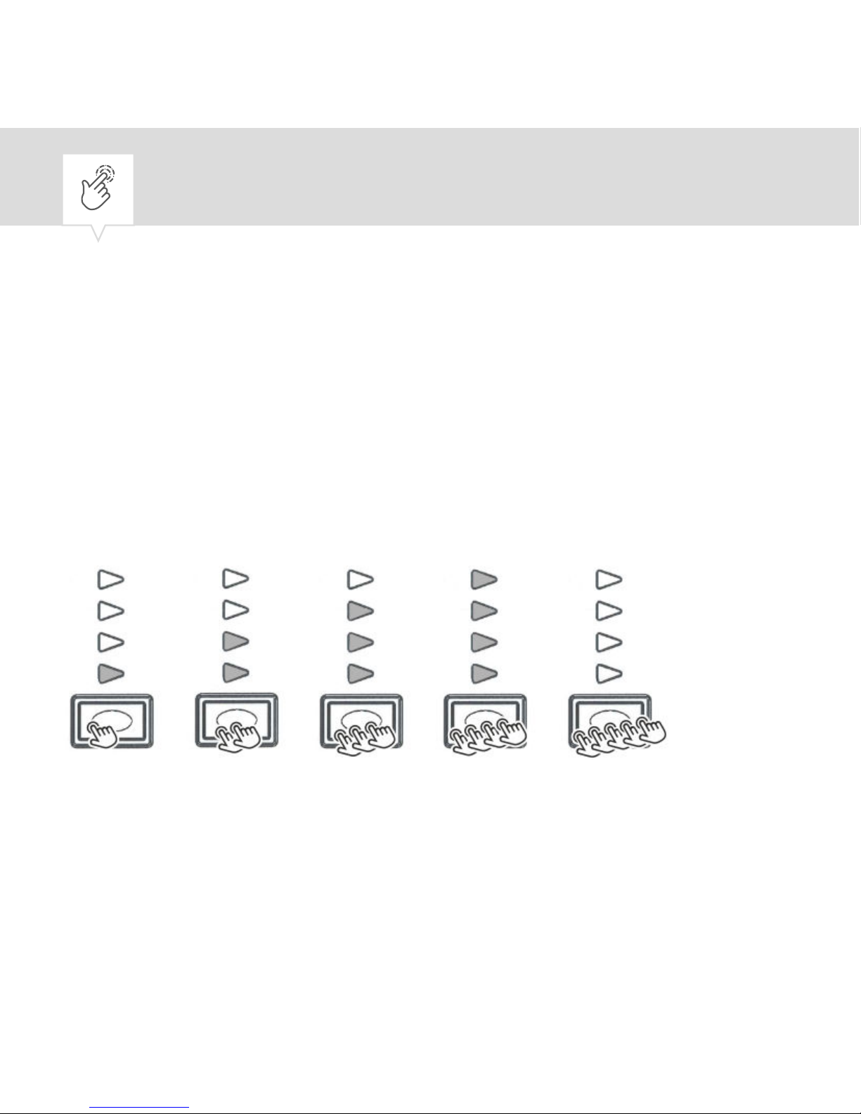
Fig. 3: LED display
[Boost]
button
1. Press the
[Boost]
button until your desired period is
set (Fig. 3).
28
Page 29
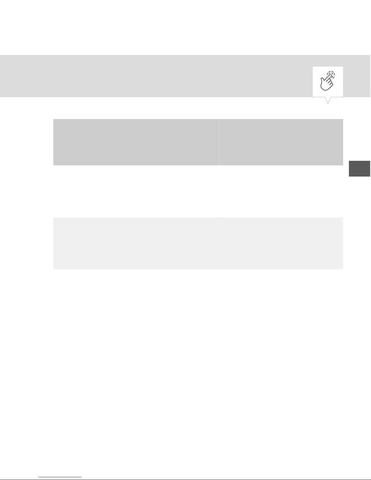
[Boost]
button
Period
(B2B)
Period (B4B)
Press first
time
1/4 h
(15 min)
1 h
Press
second time
1/2 h
(30 min)
2 h
Press third
time
1 h 3 h
EN
29
Page 30
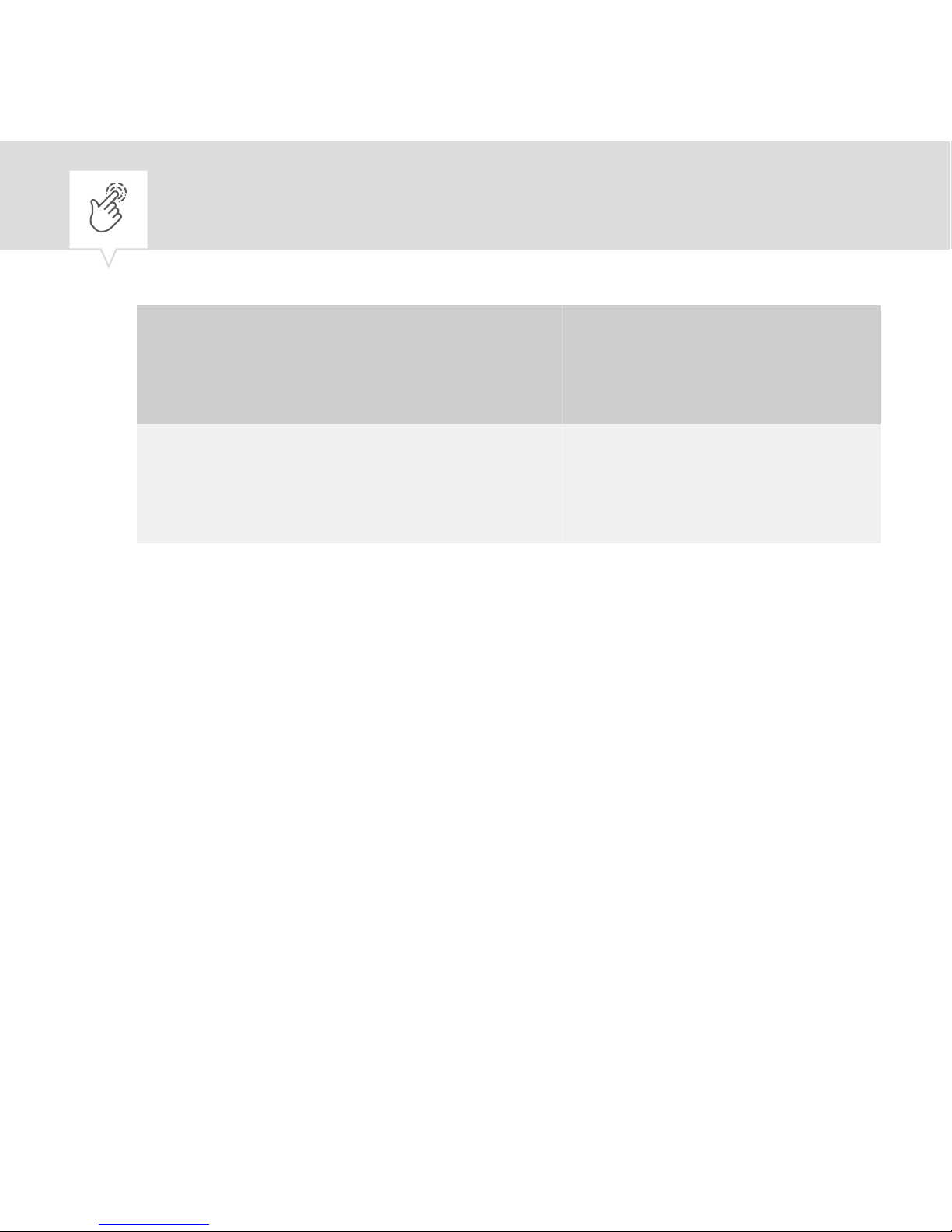
[Boost]
button
Period
(B2B)
Period (B4B)
Press fourth
time
2 h 4 h
Press fifth
time
No period
set
No period set
ð
The LEDs display the set period and the
power supply to the load is switched on. The
preselected time until the automatic switchoff begins to count down.
30
Page 31
The illuminated LEDs provide information
about the remaining time. In the final 2
minutes of a period, the corresponding LED
flashes and then goes out once the period has
expired completely.
EN
31
Page 32
Disposal
ENVIRONMENT!
Incorrect disposal presents an environmental danger.
Incorrect disposal could result in environmental dangers.
− Electric scrap and electronic components
must be disposed of correctly, i.e. the
parts for disposal must be sorted into
material groups.
32
Page 33
− Disposal must be environmentally responsible and must employ state-of-the-art
environmental protection, recycling and
disposal technology.
EN
33
Page 34

34
Page 35
EN
35
Page 36
80.10.1478.7/0217/V01
Grässlin GmbH
Bundesstrasse 36
78112 St. Georgen
GERMANY
Telephone: +49 7724 933-0
Fax: +49 7724 933-240
www.graesslin.de
 Loading...