

Page 1
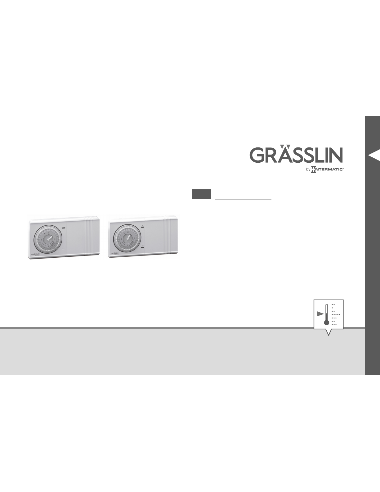
thermio™ eco B1 and B2
EN
Operating manual
Page 2
This manual ensures safe and efficient use of the timers “thermio™ eco B1” and “thermio™ eco B2”
(referred to as “device” in the following). This manual is a component of the devices and must remain
accessible at all times for everyone who uses the devices.
Everyone who uses the devices must have read and understood this manual before commencing any
work. The basic prerequisite for working safely is compliance with all safety instructions and usage
instructions specified in this manual. Furthermore, the local accident prevention regulations and the
general safety regulations in the area in which the device is operated apply.
Illustrations in this manual are intended to provide a general understanding and may differ from the
actual design.
Copyright
This manual is copyright protected.
Handover of this manual to third parties, reproductions of any type and form – including excerpts – and
use and/or disclosure of the content without the written permission of Grässlin GmbH (referred to as
“manufacturer” in the following), except for internal purposes, is not permitted. Violations will result in
liability for compensation. The manufacturer reserves the right to assert additional claims.
2
Page 3
The copyright is held by the manufacturer.
© Grässlin GmbH
Bundesstr. 36
78112 St. Georgen
GERMANY
Declaration of conformity and download instructions
The declaration of conformity for the device described in this manual, a download of the manual, and
the technical data can be found at
www.graesslin.de
.
EN
3
Page 4
Overview................................................................................................. 5
Safety................................................................................................... 11
Installation............................................................................................ 16
Electric connection and installation..................................................................................... 16
Other wiring diagrams (B1)................................................................................................. 28
Other wiring diagrams (B2)................................................................................................. 37
Operation............................................................................................. 47
Setting the time.................................................................................................................. 47
Setting the on/off time........................................................................................................ 49
Selecting the operating mode.............................................................................................. 50
Disposal................................................................................................ 53
4
Page 5
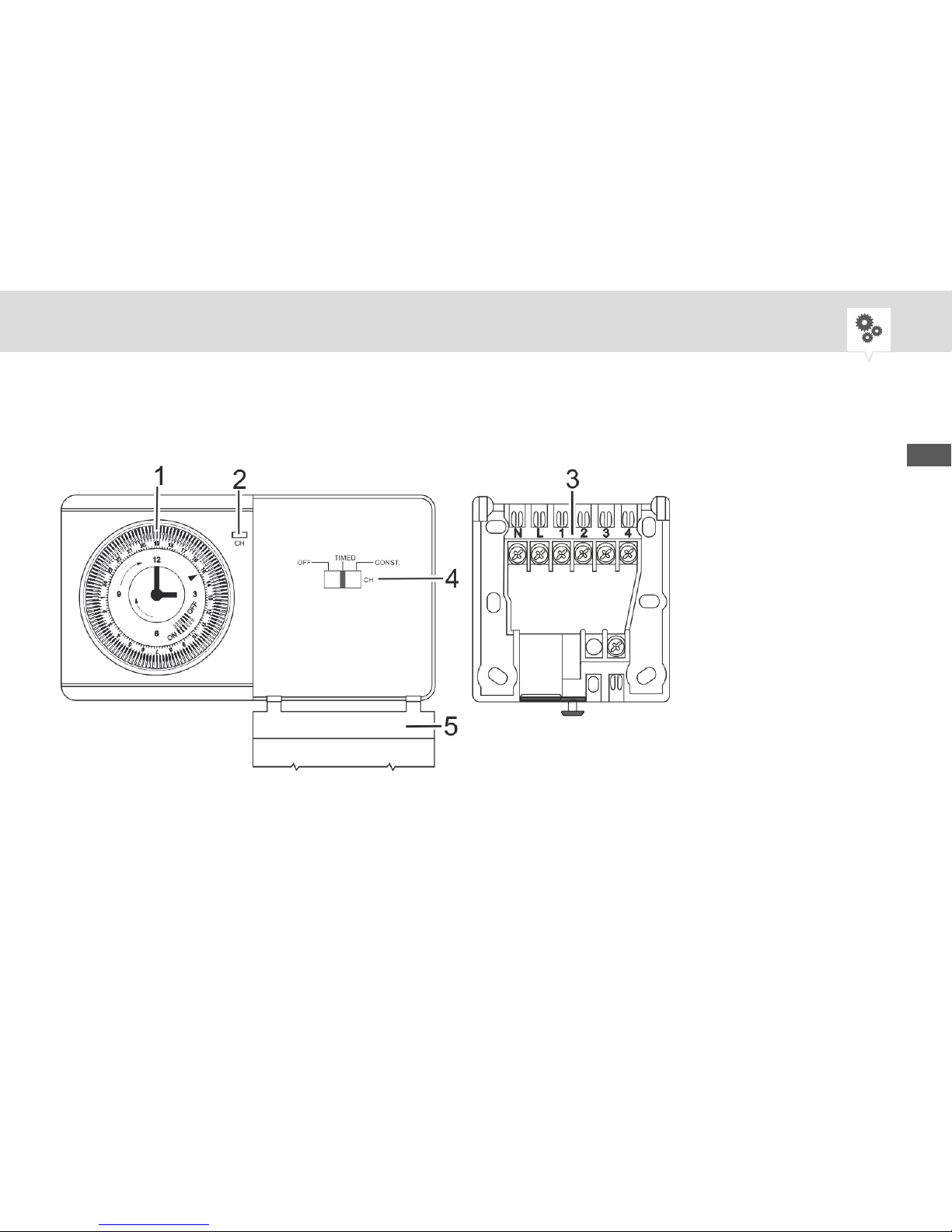
Overview
thermio™ eco B1 and mounting plate
Fig. 1: Front and side view
EN
5
Page 6

1 Dial with tappets
2 Channel 1 LED: lights up if channel is active (CH)
3 Mounting plate
4 Channel 1 manual switch (CH)
5 Cover
The “thermio™ eco B1” timer is an analogue single-channel synchronous timer that switches connected loads on and off at defined times.
The “thermio™ eco B1” timer is used to regulate a heating circuit. It can be connected to a water circuit, a heating circuit or a joint water/heating circuit. A joint water/heating circuit is then regulated
jointly. Simultaneous regulation of, for example, central heating and hot water is implemented using just
one switching output.
6
Page 7
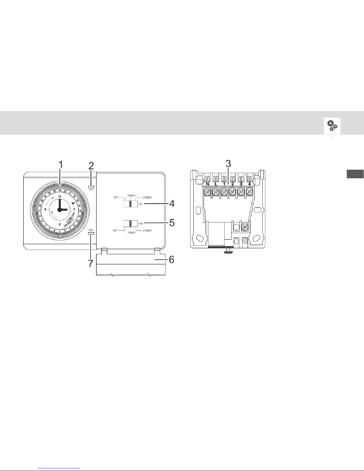
thermio™ eco B2 and mounting plate
Fig. 2: Front and side view
EN
7
Page 8

1 Dial with tappets
2 Channel 1 LED: lights up if channel is active (CH)
3 Mounting plate
4 Channel 1 manual switch (CH)
5 Channel 2 manual switch (HW)
6 Cover
7 Channel 2 LED: lights up if channel is active (HW)
The “thermio™ eco B2” timer is an analogue two-channel synchronous timer that switches connected
loads on and off at defined times.
The “thermio™ eco B2” timer is used to regulate two heating circuits. Hot water or heating circuits can
be connected and regulated independently of each other in the OFF and CONST. operating mode. In
TIME operating mode, the two heating circuits are regulated together, according to the setting of the ON
or OFF tappets. Individual regulation of, for example, central heating and hot water is implemented using
two independent switching outputs.
Abbreviations
• CH = Central Heating
• HW = Hot Water
8
Page 9
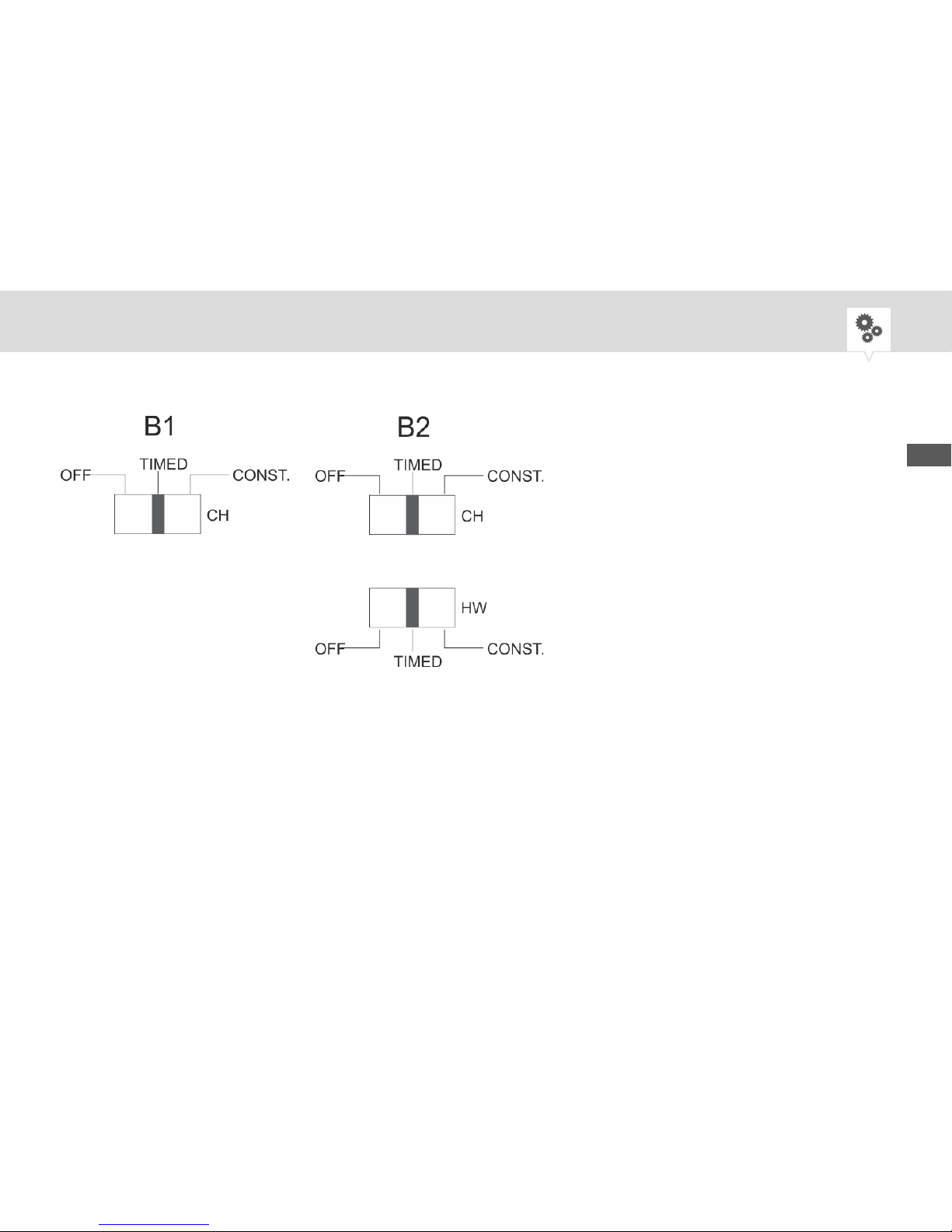
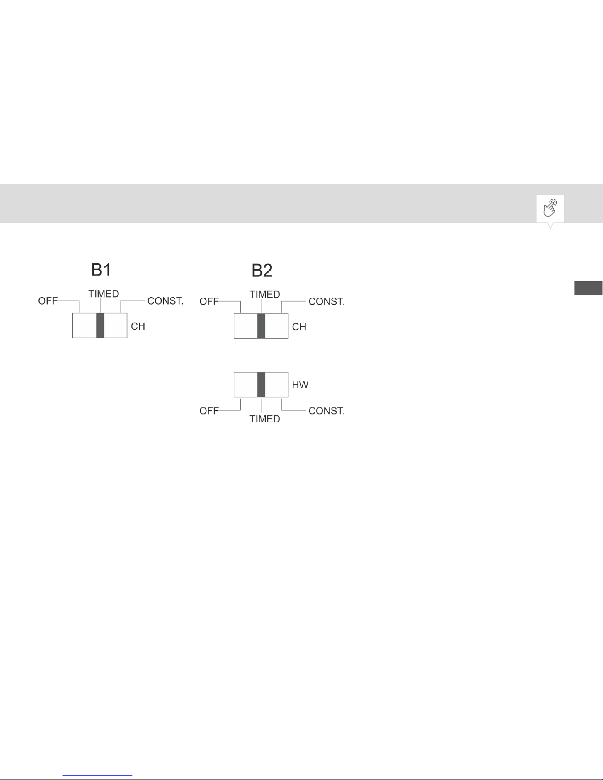
Manual switch
Fig. 3: Manual switch
The “thermio™ eco B1” single-channel timer has one manual switch and the “thermio™ eco B2” twochannel timer has two manual switches, one for each channel.
In the “thermio™ eco B2” two-channel timer, the two channels can be set independently of each other.
If a channel is switched on, the corresponding LED lights up (Fig. 1/2 and Fig. 2/2, 7).
EN
9
Page 10

Positions Effects
OFF Permanently switched off.
TIMED Automatic mode, switches according to the set-
ting of the ON or OFF tappets.
CONST. Permanently switched on.
10
Page 11
Safety
Safety instructions
Safety instructions are indicated in this manual by symbols. The safety instructions are introduced by
signal words that express the extent of the danger.
WARNING!
This combination of symbol and signal word indicates a potentially dangerous
situation that may result in death or severe injuries if the situation is not
avoided.
NOTICE!
This combination of symbol and signal word indicates a potentially dangerous
situation that may result in material damage if the situation is not avoided.
EN
11
Page 12
ENVIRONMENT!
This combination of symbol and signal word indicates potential dangers for
the environment.
Tips and recommendations
This symbol highlights useful tips and recommendations, as well as information for efficient and fault-free operation.
Intended use
The “thermio™ eco B1” and “thermio™ eco B2” timers are used exclusively for timer regulation of
heating systems and hot water circuits in a temperature range from -10°C to +50°C. The connected
devices must comply with the limits specified in the technical data.
12
Page 13
Areas of application:
• Boiler
• Combination boiler
• Domestic heating technology for heating and water heating
• Pump-controlled central heating systems with two-way spring-loaded check valves
• Pump-controlled central heating systems with three-way valves
• Gravity heating systems with or without valves
• Gravity heating with room thermostat
The intended use also includes compliance with all information specified in this manual.
Any use other than the intended use is considered incorrect use. The legal warranty is voided by any
interference with, or modifications to, the device.
Residual risks
The device is state-of-the art and designed in accordance with current safety requirements. However,
residual risks remain that require caution when using the device. The residual risks, and the conduct
and measures they require, are listed in the following.
EN
13
Page 14
WARNING!
Danger to life due to electric shock!
Improper assembly and installation of the device may result in life-threatening electrical voltages.
− Have assembly and connection performed by a qualified electrician only.
WARNING!
Danger due to insufficient wire cross-section!
If wires with an insufficiently large cross-section are used, short circuits or
fires may occur.
− For the flexible wires, only use terminals with a maximum cross-section
of 4 mm².
14
Page 15
Personnel requirements
Qualified electrician
Professional training, knowledge and experience, and knowledge of the relevant standards and regulations allows the qualified electrician to perform work on electrical systems and to identify, and avoid,
potential dangers of their own accord.
A qualified electrician is specifically trained for the work environment in which they work, and are
familiar with the relevant standards and regulations.
User
The user is the person who uses and operates the device in compliance with proper use, without any
prior knowledge.
EN
15
Page 16

Installation
Electric connection and installation
The device is mounted on the wall. If mounted on the wall, the connection wires either come directly out
of the wall or they are routed to the device on top of the wall.
In general, the following instructions apply to both connection wire options.
Where there are differences, the corresponding installation type is specified
before the instructions.
WARNING!
Danger to life due to electric shock!
Improper assembly and installation of the device can lead to life-threatening
electrical voltages.
− Have assembly and connection performed by a qualified electrician only.
16
Page 17

NOTICE!
Danger of material damage to wires in the wall!
Selecting the wrong installation position can result in material damage to any
wires in the wall.
− Make sure that there are no wires in the wall at the installation position.
Personnel:
• Qualified electrician
Special tool:
• Power drill
• Drill
• Flat-head screwdriver
• Phillips screwdriver
Prerequisite:
• The terminals for the flexible wires have a maximum cross-section of 4 mm².
EN
17
Page 18
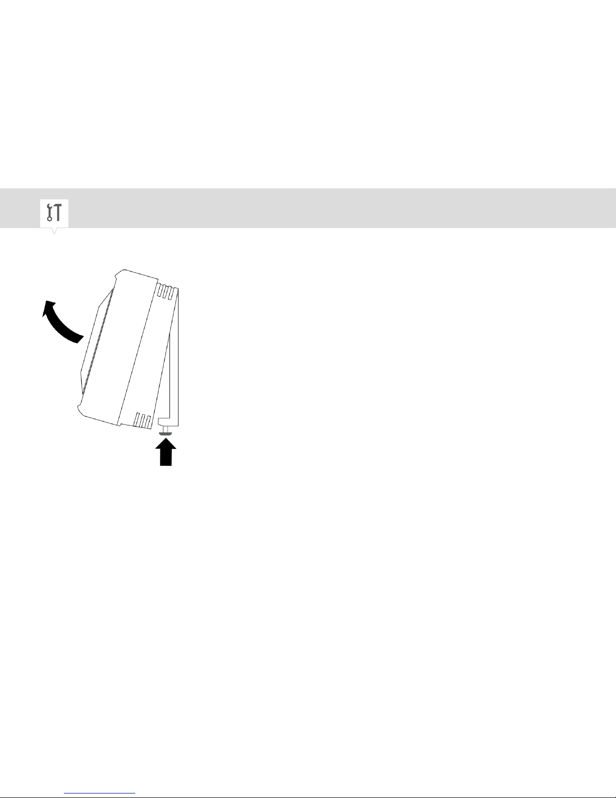
Removing the mounting plate
Fig. 4: Undo the mounting plate from the device housing
1. Undo the safety screw on the device housing (Fig. 4) with the flat-head screwdriver.
18
Page 19
The screw in the mounting plate is captive, in other words you can
loosen it but you cannot remove it.
EN
19
Page 20
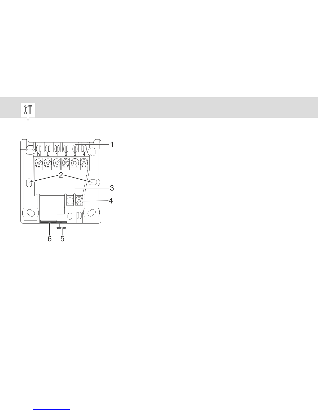
2. Remove the mounting plate.
Fig. 5: Mounting plate
1 Connection terminal strip
2 Mounting holes
3 Cable feed-through
4 Earth contact
5 Safety screw
6 Defined breaking point for cable feed-
through
20
Page 21
3.
When selecting the installation position, make sure that a distance of at
least 4 cm is left free below the mounting plate to leave space to open
the cover and undo the safety screw.
Mark the hole pattern from the mounting plate (Fig. 5/2) onto the wall.
4. Drill holes at the points you marked.
5. Insert suitable wall-plugs for the screws into the holes.
6. Connection wires directly out of the wall: Thread the connection wire into the device through the
cable feed-through (Fig. 5/3).
7. On-wall connection wires: Break out the necessary defined breaking point (Fig. 5/6) and thread
through the connection wires.
EN
21
Page 22
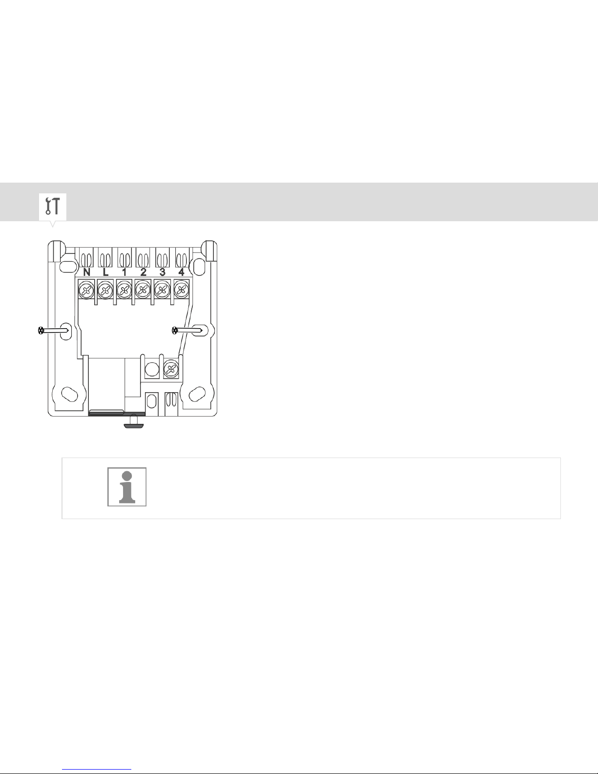
Fig. 6: Installing the mounting plate
8.
If installing in a flush-mounted socket, use machine screws.
Use wood screws for on-wall mounting,
Fasten the mounting plate with the screws (Fig. 6).
22
Page 23
Connecting
9. Strip insulation from the connection wires.
• Stripping length: 8 mm
10.
The housing is doubly insulated (protection class 2) so no earthing con-
nection is necessary. To improve the appearance, insert the earth connection into the earth terminal.
Insert the earth connection wires into the earth contact (Fig. 5/4).
To ensure that the wiring is correct, consult the operating manual for the
heating system in use.
EN
23
Page 24
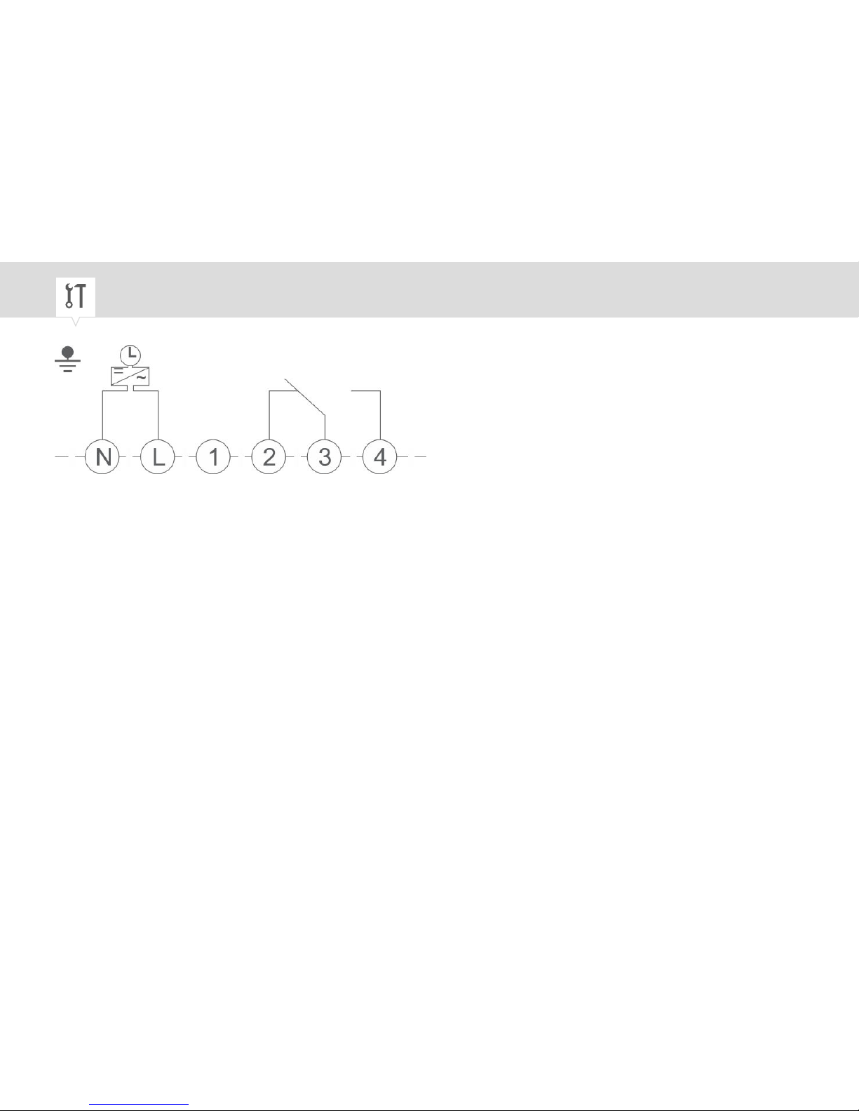
Fig. 7: “thermio™ eco B1” wiring diagram
N Neutral conductor
L Live conductor
1 Not assigned
2 NC (normally closed contact) (OFF)
3 COM (changeover contact, common conductor contact)
4 NO (normally open contact) (ON)
24
Page 25
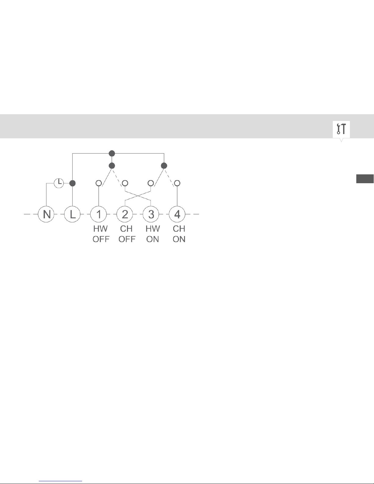
Fig. 8: “thermio™ eco B2” wiring diagram
N Neutral conductor
L Live conductor
1 NC (normally closed contact) (HW) (OFF)
2 NC (normally closed contact) (CH) (OFF)
3 NO (normally open contact) (HW) (ON)
4 NO (normally open contact) (CH) (ON)
11. Insert the connection wires for the device into the corresponding terminals (Fig. 5/1) in accordance
with the wiring diagram (Fig. 8 or Fig. 7).
EN
25
Page 26

12.
NOTICE!
Tightening torques
To avoid damage and faulty contacts, tighten the terminals using a
torque of 0.6 Nm.
Tighten all terminals using the Phillips screwdriver.
26
Page 27
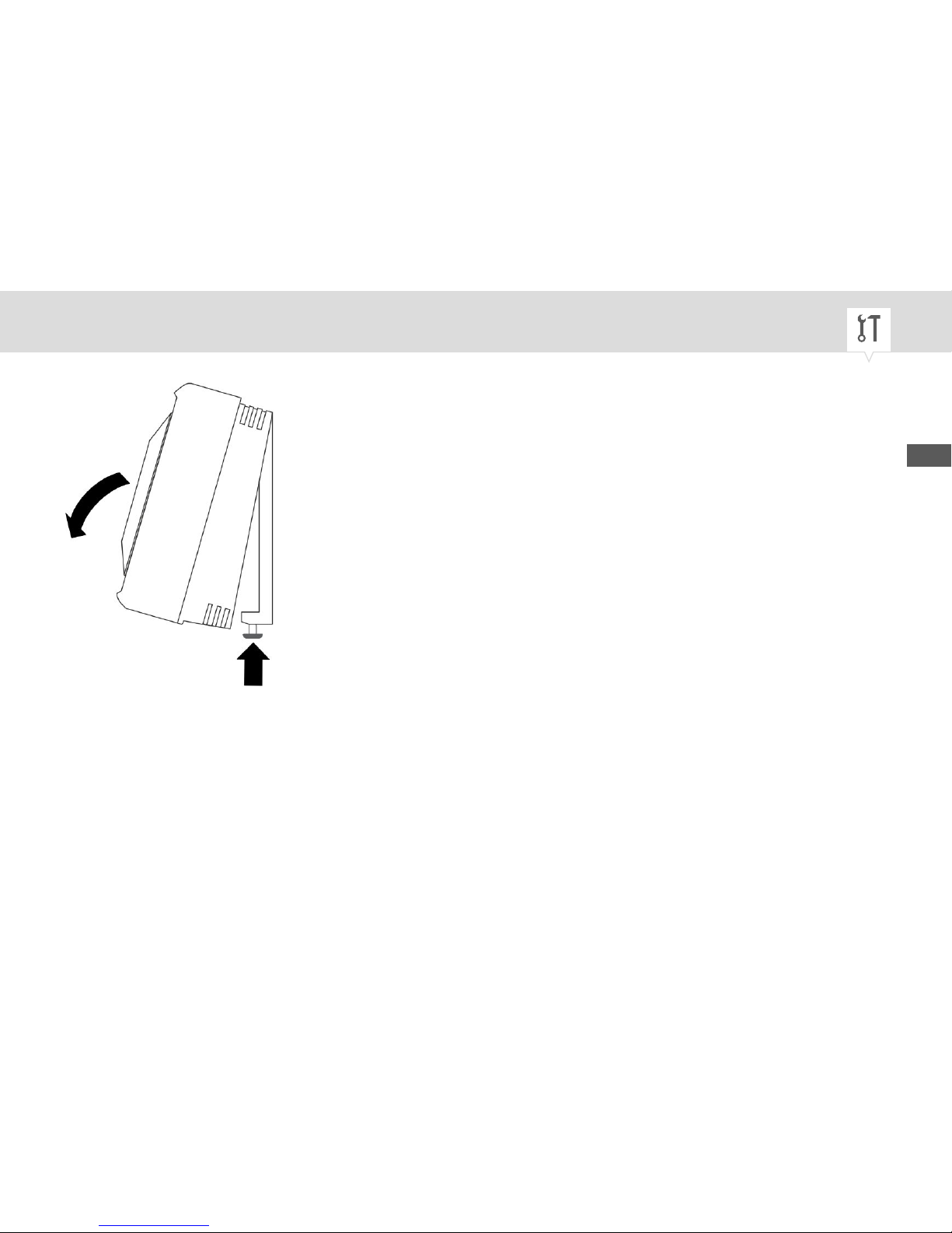
Fig. 9: Installing the housing on the mounting plate
13. Clip on the device housing and place it on the mounting plate (Fig. 9).
14. Tighten the safety screw on the device housing (Fig. 9) with the flat-head screwdriver.
ð
The device is now fully installed.
EN
27
Page 28
Other wiring diagrams (B1)
The wiring diagram for the lines depends on the heating system (central heating systems, gravity
heating systems etc.). The wires need to be connected according to the components that are to be connected (room thermostat, contact thermostat etc.) and the installation type of the heating system.
To ensure that the wiring is correct, consult the operating manual for the
heating system in use.
Personnel:
• Qualified electrician
28
Page 29
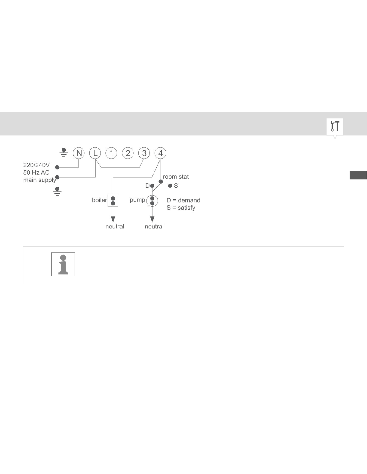
Fig. 10: Pump-controlled central heating systems
This diagram is suitable for mains connection; connection wire L – 3 has to
be connected here.
EN
29
Page 30

Room thermostat table
Model E N common demand satisfy
Tower SS E 4 1 2 –
Tower SSTRS E 4 1 3 –
ACL TS 142 E 4 1 2 –
Drayton RTE E 4 1 2 3
Honeywell T 6160B – 2 1 3 4
Landis&Gyr RAD 5 – 4 6 2 –
Switchmaster SRT2 5 – 1 3 2
Sunvic TLX2259 E 4 3 1 –
30
Page 31
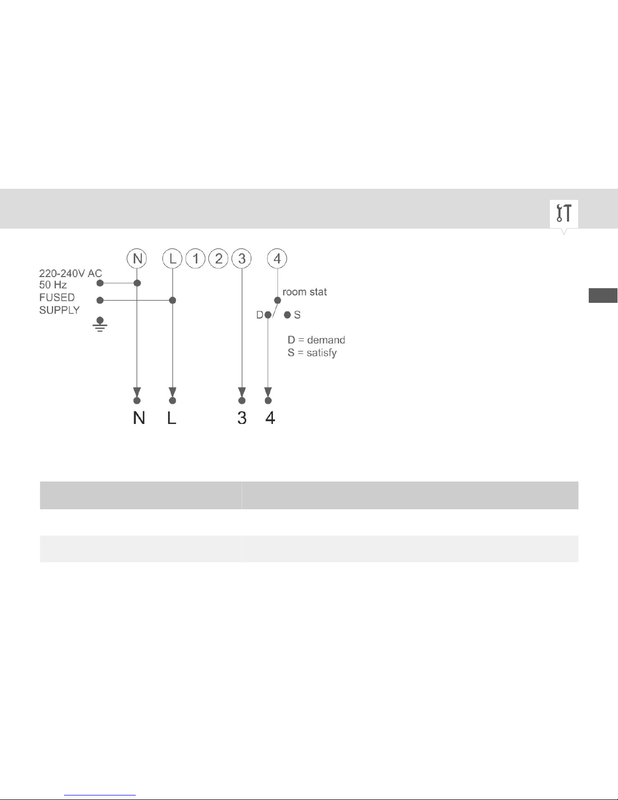
Fig. 11: Combination boiler
Combination boiler table
Model
Fig. 11/N Fig. 11/L Fig. 11/3 Fig. 11/4
Chaffoteux Celtix 2.20 OFF N PH 7 6
EIM Leblanc GVM 420 see Fig. 13
EN
31
Page 32

Model
Fig. 11/N Fig. 11/L Fig. 11/3 Fig. 11/4
Glowworm Fuelsaver N L 8 7
Ravenheat N L C D
Saunier Duval SD 620 F N L 2 3
Saunier Duval SD 123C N L 2 1
Saunier Duval SD 235C N L 2 1
Saunier Duval SD 135C N L 2 1
Saunier Duval SD 625M see Fig. 12
Vaillant VCW 20/1 T3W 1MP 2R 3 4
Vaillant VCW 25/1 T3W 1MP 2R 3 4
Vaillant VCW Sine 18 T3W 1MP
N
2R
L
3 4
32
Page 33

Model
Fig. 11/N Fig. 11/L Fig. 11/3 Fig. 11/4
Vaillant VCW GB 182 EH 1 2 3 4
Vaillant VCW GB 242 EH 1 2 3 4
Vokera 18/72 MCF N L 4 5
Vokera 21/84 MCF N L 4 5
Vokera 21/84 TURBO N L 4 5
Vokera 18/72 DMCF N L 3 4
Vokera 21/84 DMCF N L 3 4
Vokera 21/84 DC TURBO N L 3 4
Vokera 20/80 RS TURBO N L 3 4
Worcester Heatslave Senior 12 N L 2 4
Worcester Heatslave Senior 20430 N L 2 4
EN
33
Page 34
Model
Fig. 11/N Fig. 11/L Fig. 11/3 Fig. 11/4
Worcester Heatslave Senior 6 N L 2 6
Worcester Heatslave 9-24 RSF N L 1 2
Worcester Heatslave 9-24 BF N L 1 2
Worcester Heatslave 9-24 OF N L 1 2
Worcester Heatslave High Flow BF N L 2 2
Worcester Heatslave High Flow OF N L 2 3
Saunier Duval SD 625M
Always use the special 24 V thermostat that is delivered together with this
boiler, and complete the wiring as specified in the manual for the boiler, but
exchange timer terminals A and B for connection terminals 3 or 4 to B1.
34
Page 35
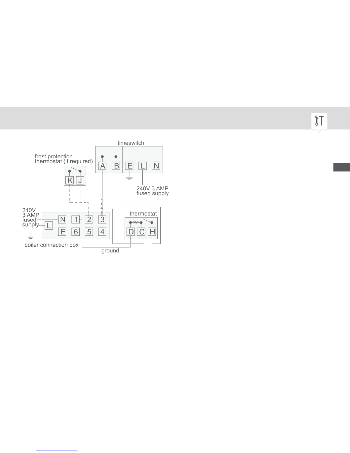
Fig. 12: Saunier Duval SD 625M
EN
35
Page 36
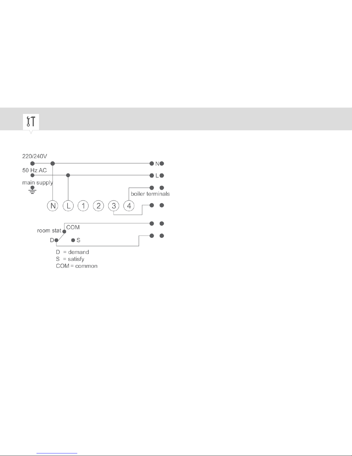
ElM Leblanc GVM 420
Fig. 13: ElM Leblanc GVM 420
36
Page 37
Other wiring diagrams (B2)
The following circuit diagrams are not complete (the earth and neutral conductors have been omitted to
aid clarity). When connecting the systems, we recommend using a suitable cable junction box. For connection information, consult the documentation from the manufacturer of the cable junction box.
To ensure that the wiring is correct, consult the operating manual for the
heating system in use.
EN
37
Page 38
For the (B2) wiring diagrams, the following combinations of manual switch
position and effect on the system cannot be assigned:
− OFF
− Permanently switched off.
− TIMED
− Automatic mode, switches according to the setting of the ON or OFF
tappets.
− CONST.
− Permanently switched on.
38
Page 39
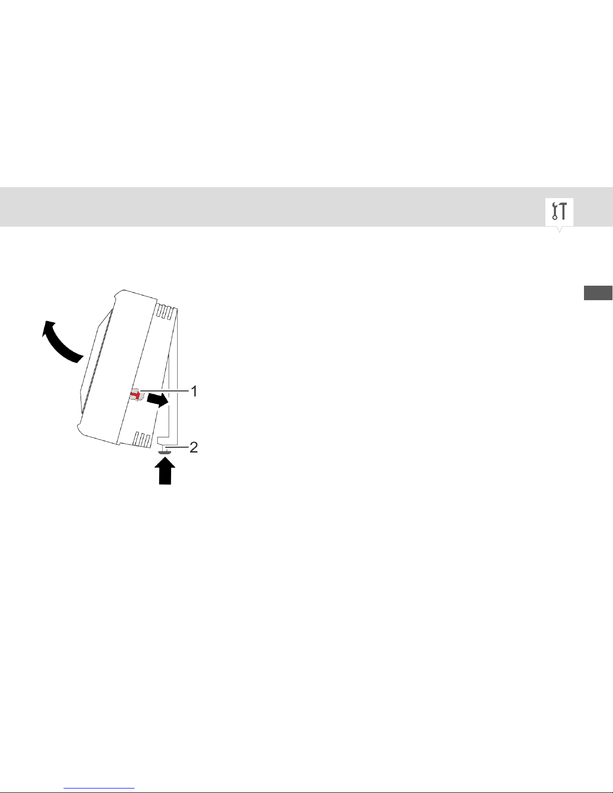
Gravity heating
To control a gravity heating system, the red pin on the timer has to be removed.
Fig. 14: Removing the red pin
1. Undo the safety screw on the device housing (Fig. 14/2) with the flat-head screwdriver.
2. Remove the device housing from the mounting plate.
EN
39
Page 40
3. Pull the red pin (Fig. 14/1) out of the device housing.
Keep the red pin (Fig. 14/1) in a safe place for future use.
4. Clip on the device housing and place it on the mounting plate.
5. Tighten the safety screw (Fig. 14/2) on the device housing using a flat-head screwdriver.
40
Page 41
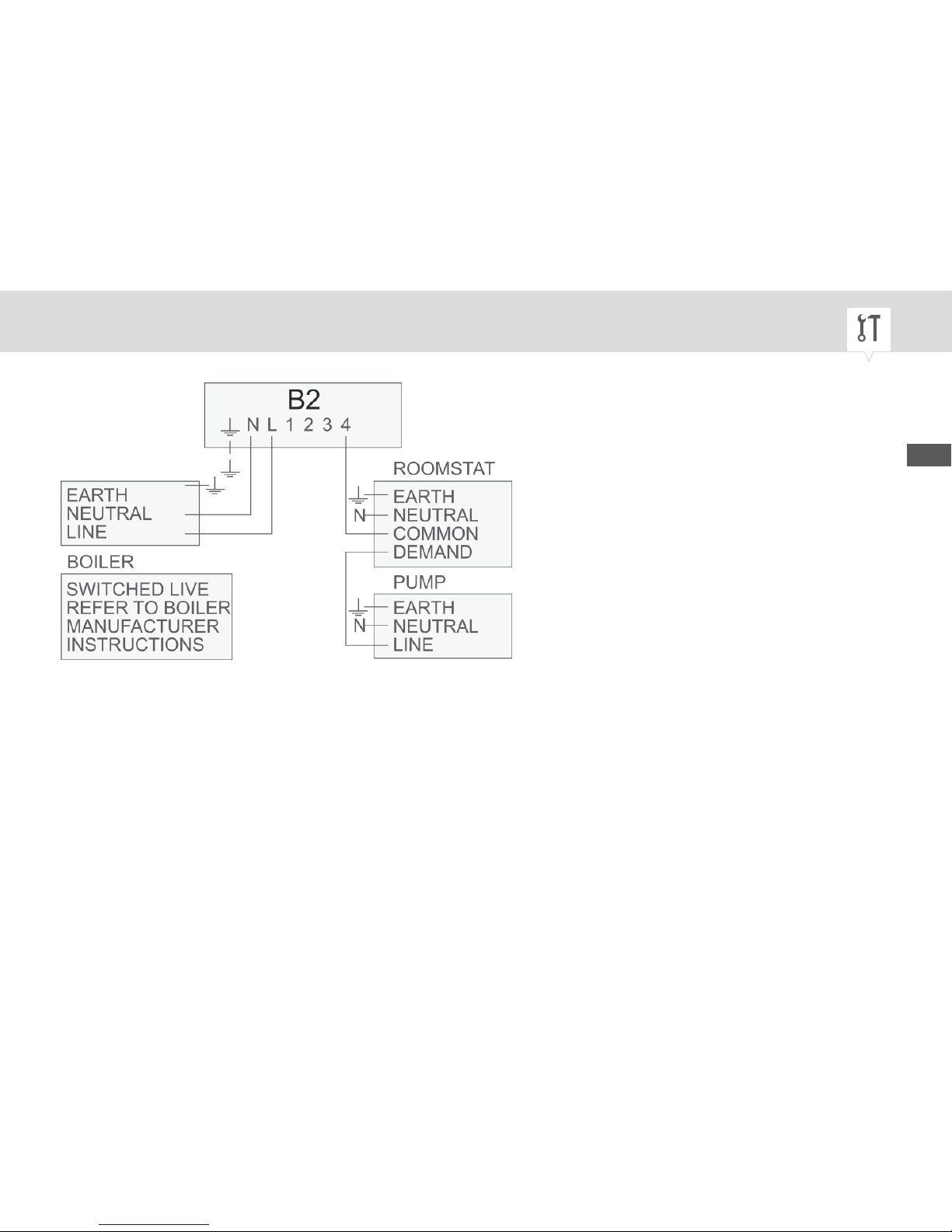
Fig. 15: Gravity heating with room thermostat
EN
41
Page 42
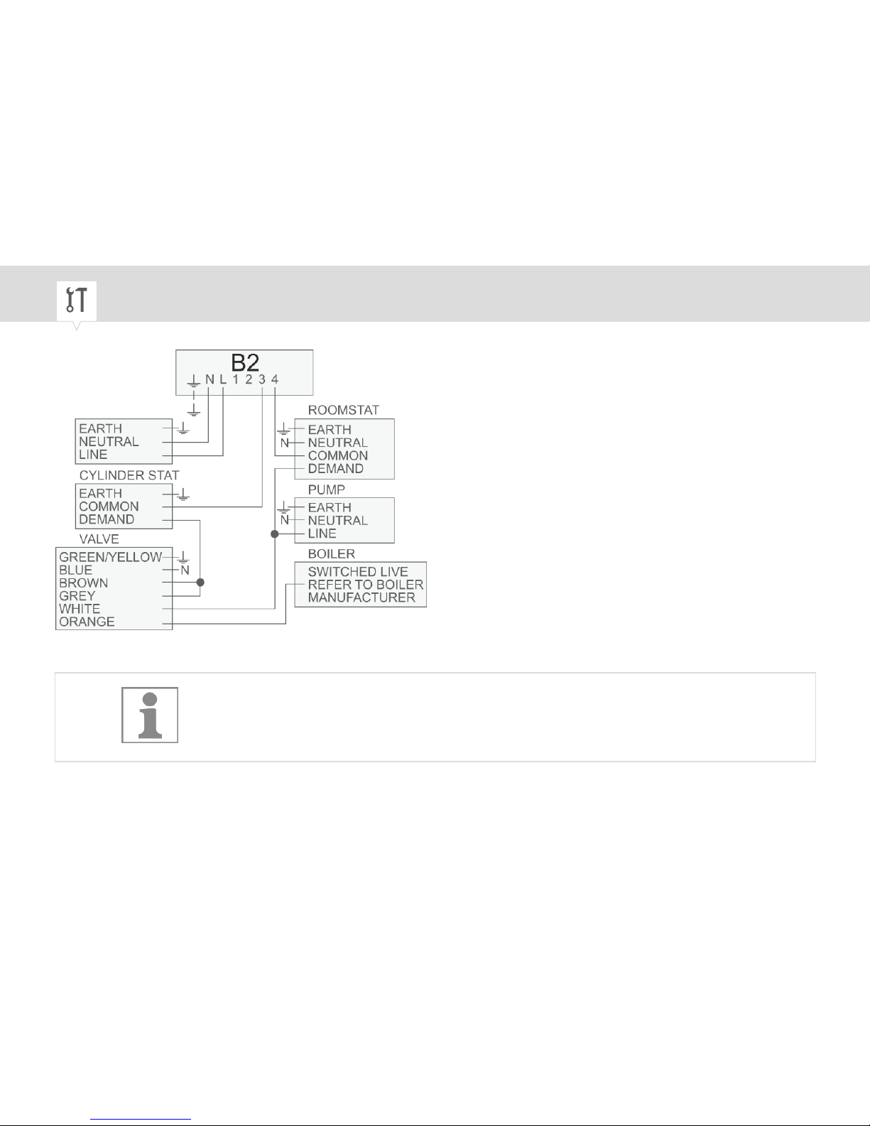
Fig. 16: Gravity heating with valves
Only valves with switch-over limit switches are suitable.
42
Page 43
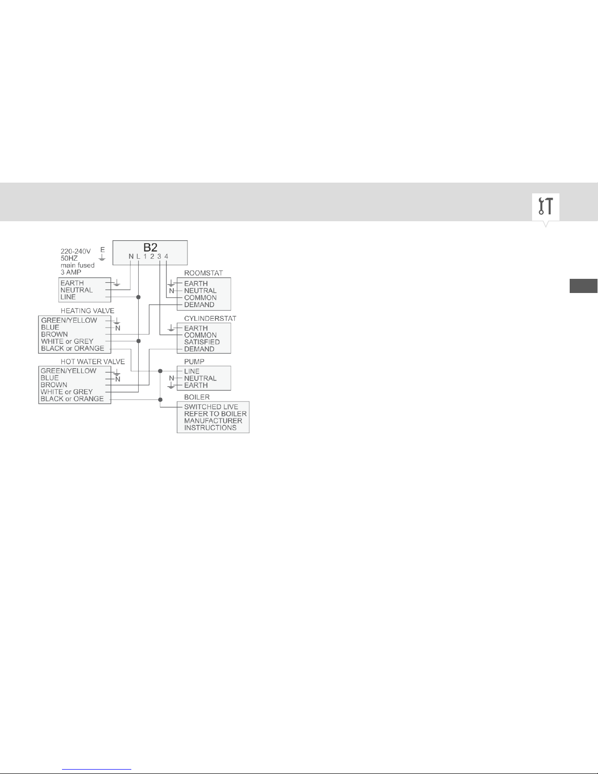
Fig. 17: Pump-controlled central heating systems with two-way spring-loaded check valves
EN
43
Page 44
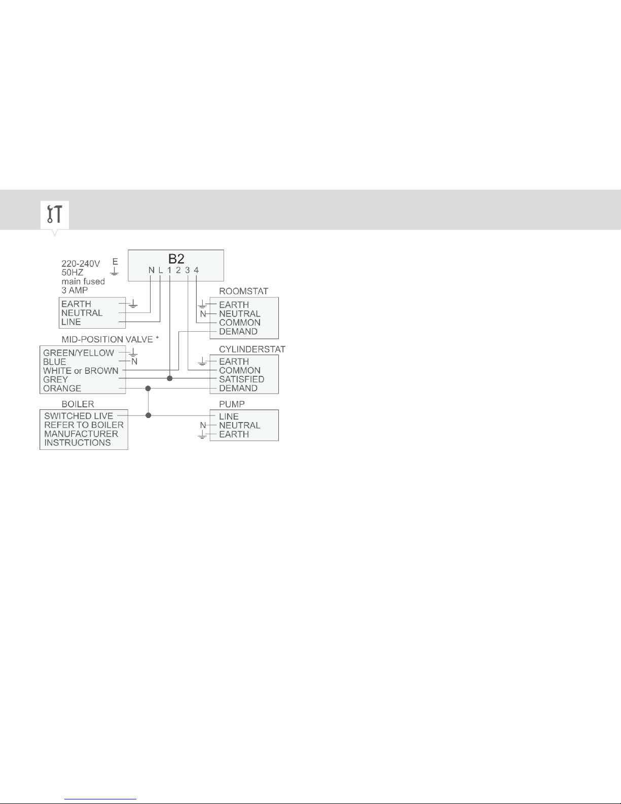
Fig. 18: Pump-controlled central heating systems with three-way valves
* TOWER MP322C, ACL 697B340, DRAYTON FLOW SHARE 2, HONEYWELL V4073A, LANDIS &
GYR SK 3L, SUNVIC SD 1701
44
Page 45
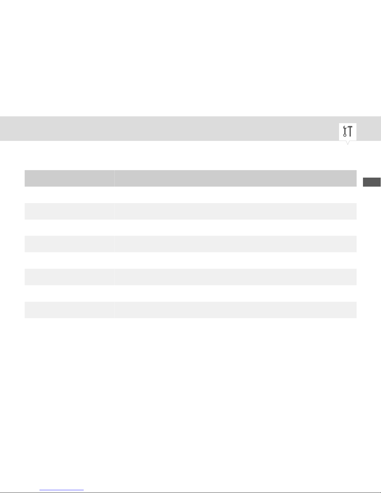
Room thermostat table
Model E N common demand satisfy
Tower SS E 4 1 2 –
Tower RS E 4 1 3 –
ACL TS 142 E 4 1 2 –
Drayton RTE E 4 1 2 3
Honeywell T 6160B – 2 1 3 4
Landis&Gyr RAD 5 – 4 6 2 2
Switchmaster SRT2 5 – 1 3 –
Sunic TLX2259 E 4 3 1 –
EN
45
Page 46

Contact thermostat table
Model E common demand satisfy
Tower CS1 – Red Black Yellow
ACL HTS 2 –
Drayton CS1 E 1 2 3
Honeywell L641 A – C 1 2
Landis&Gyr RAM 21 – 1 2 3
Switchmaster SCT – 1 2 3
Sunvic SA 2451 E 3 1 2
46
Page 47
Operation
Setting the time
Personnel:
• User
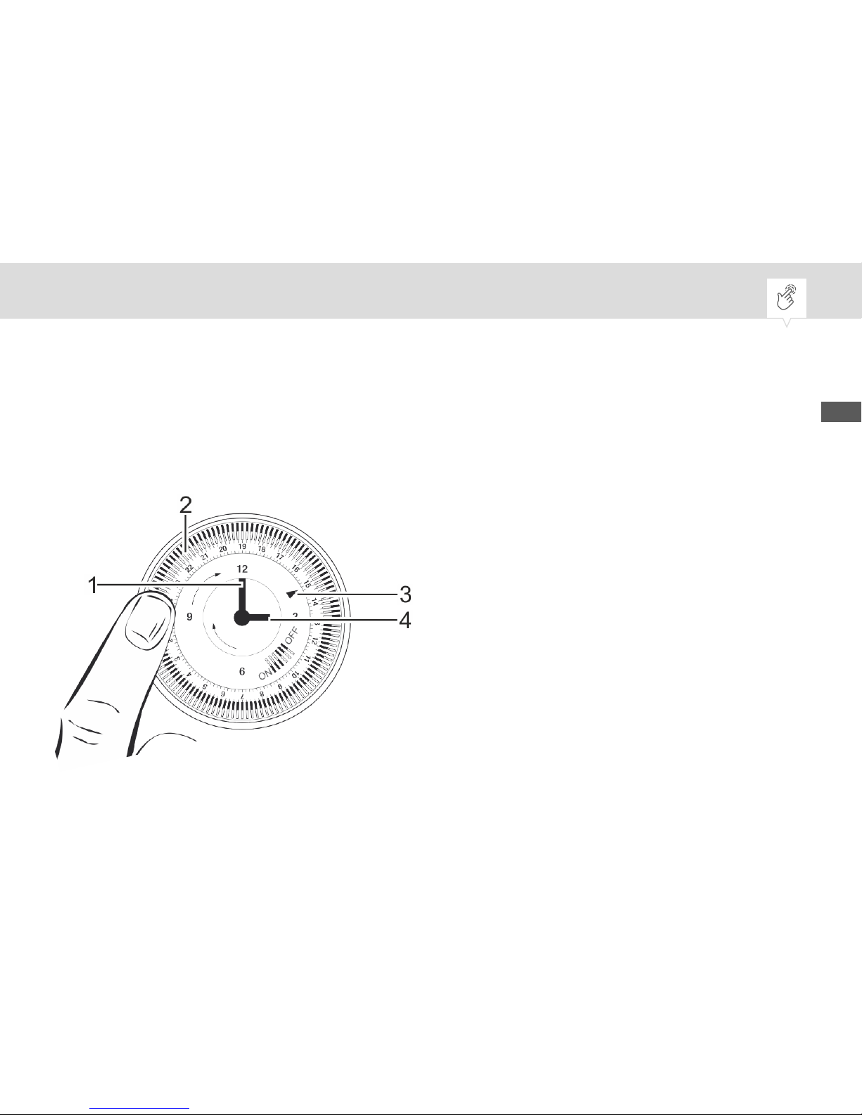
Fig. 19: Setting the time
EN
47
Page 48
1 Minute hand
2 Dial with tappets
3 Indicator marker
4 Hour hand
1.
NOTICE!
Risk of material damage due to turning anti-clockwise!
Turning the dial or the clock hand anti-clockwise can result in material
damage to the timer.
− Make sure to turn the dial and clock hand clockwise only.
To roughly set the time, turn the dial (Fig. 19/2) clockwise until the indicator marker (Fig. 19/3)
points to the current time.
In 12 hour display: 6:00 = 6.00 (a.m.) and 16:00 = 4.00 (p.m.)
The timer does not distinguish between summer and winter time. As a
result, you have to set the summer and winter time manually by
adjusting the current time.
48
Page 49
2. To finely adjust the time, turn the minute hand (Fig. 19/1) clockwise until the time indicated by the
indicator marker (Fig. 19/3) matches the current time.
ð
The dial and the clock hand rotate together with the current time.
Setting the on/off time
Personnel:
• User
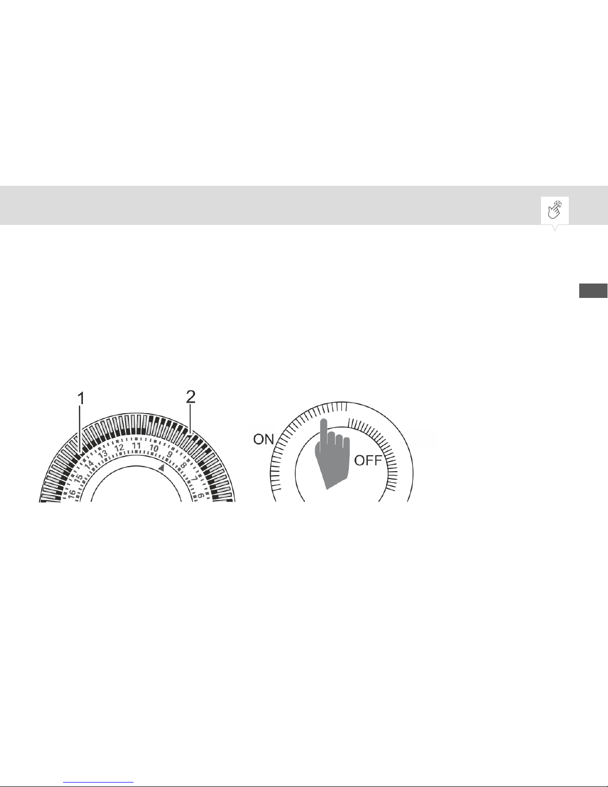
Fig. 20: Setting the tappets
EN
49
Page 50
1.
Each tappet represents 15 minutes of switching time.
If the tappets are pushed inwards, the heating system is switched off
during that time; if the tappets are pushed outwards, the heating system
is switched on during that time.
Push the tappets to OFF (Fig. 20/1) or ON (Fig. 20/2), according to your desired switching times.
2. To activate the timer, switch the manual switch to the TIMED operating mode.
Selecting the operating mode
Personnel:
• User
Prerequisite:
50
Page 51
• Cover is open.
Fig. 21: Manual switch
1. Switch the manual switch to the desired position.
ð
The device reacts according to the position.
EN
51
Page 52

Positions Effects
OFF Permanently switched off.
TIMED Automatic mode, switches according to the set-
ting of the ON or OFF tappets.
CONST. Permanently switched on.
52
Page 53
Disposal
ENVIRONMENT!
Environmental hazard!
Incorrect disposal could result in environmental dangers.
− Electric scrap and electronic components must be disposed of correctly,
i.e. the parts for disposal must be sorted into material groups.
−
Disposal must be environmentally responsible and must employ stateof-the-art environmental protection, recycling and disposal technology.
EN
53
Page 54

54
Page 55

EN
55
Page 56

80.10.1476.7/0217/V01
Grässlin GmbH
Bundesstrasse 36
78112 St. Georgen
GERMANY
Telephone: +49 7724 933-0
Fax: +49 7724 933-240
www.graesslin.de
 Loading...