

Page 1
Die Montage/Installation muß
von einer Fachkraft oder unter
deren Leitung und Aufsicht
durchgeführt und geprüft
werden.
Hinweise zur Montage:
– nur PVC-Mantelleitung
(Massivdraht) für die
Installation verwenden
– nur auf nicht leitfähigem,
ebenem und festem Untergrund montieren
– nur für den Einsatz bei Um-
gebungsbedingungen mit
üblicher Verunreinigung
geeignet
– bei sachgemäßer Montage
nach VDE 0100 Teil 40,
können die dann noch berührbaren Teile als doppelt
isoliert (Schutzklasse II) angesehen werden
Hinweise für den Betrieb:
Die Elektronik dieses Gerätes
ist gegen Störungen von außen
weitgehend geschützt.
Es ist jedoch zu beachten – je
nach Montageart – daß der
Netzspannung extrem starke
Störspannungsspitzen überlagert sein können.
Auch beim Schalten von Spulen,
z. B. Magnetventile, Schütze,
treten Störungen auf, die ein
elektronisches Gerät trotz aller
internen Schutzmaßnahmen
beeinflußen können.
Um größtmögliche Betriebssicherheit zu gewährleisten, müssen
beim Anschluß folgende Details
beachtet werden:
– bei größeren Anlagen ist es
erforderlich, Spulen, z. B.
Magnetventile, Schütze, die
direkt vom Gerät geschaltet werden, mit einem passenden Varistor oder RCGlied zu entstören
– werden induktive Gleich
spannungsverbraucher
geschaltet, muß eine Löschdiode dazugeschaltet werden
– Leuchtstofflampen, sowohl
induktive wie auch kapazitive
Lasten, stellen für die Ausgangskontakte eine beson-
dere Beanspruchung dar.
Prüfen Sie im Einzelfall, ob
der Einbau einer weiteren Baugruppe angebracht ist.
– Trennrelais oder Schütz bzw.
– Netz-Entstörfilter
Installationshinweise
thermio
WA-EKF 3641/03.00/S:MMS/D:Str/99/00794/80.10.0872.7
Montage/Anschluß – Assembly/Operation – Montage/Fonctionnement – Montaje/Conexión – Montage/Bediening – Montaz/Obsługa – Montáz/Obsluha – Szerelés/Kezelés
1
4
2 3
5
6 7 8
Bedienung – Operation – Fonctionnement – Conexión – Bediening – Obsługa – Obsluha – Kezelés
a)a)
b)
c)
d)
Page 2
1
2
3
4
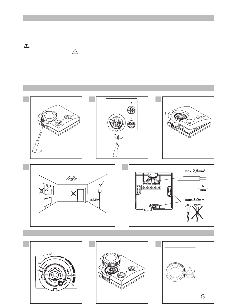
Montage/Anschluß
D
Einstellknopf mit geeignetem Werkzeug abheben
Befestigungsschraube lösen
Gehäuseoberteil abnehmen
Geeigneten Montageort bestimmen
5
– Der Anschluß muß von einer Fachkraft mit entsprechender
Sorgfalt durchgeführt werden
– Vor der Montage Heizungsanlage ausschalten
– Überprüfen und sicherstellen, daß die Anschlußdrähte keine
Spannung führen.
– Anschlußleitungen durch die Öffnung im Gerätesockel führen
– Sockel auf festen, ebenen Grund oder UP-Dose montieren
– Anschlußdrähte fachgerecht abisolieren und dem Schaltbild
entsprechend anschließen, siehe Geräteaufkleber.
Die Regelgenauigkeit wird nur erreicht, wenn die angegebene
Stromaufnahme eingehalten wird.
Kennen Sie die Stromaufnahme des Verbrauchers?
Im Zweifelsfalle prüfen!
Wählen Sie beim Anschluß die richtige Anschlußklemme!
6
7
8
Bedienung
D
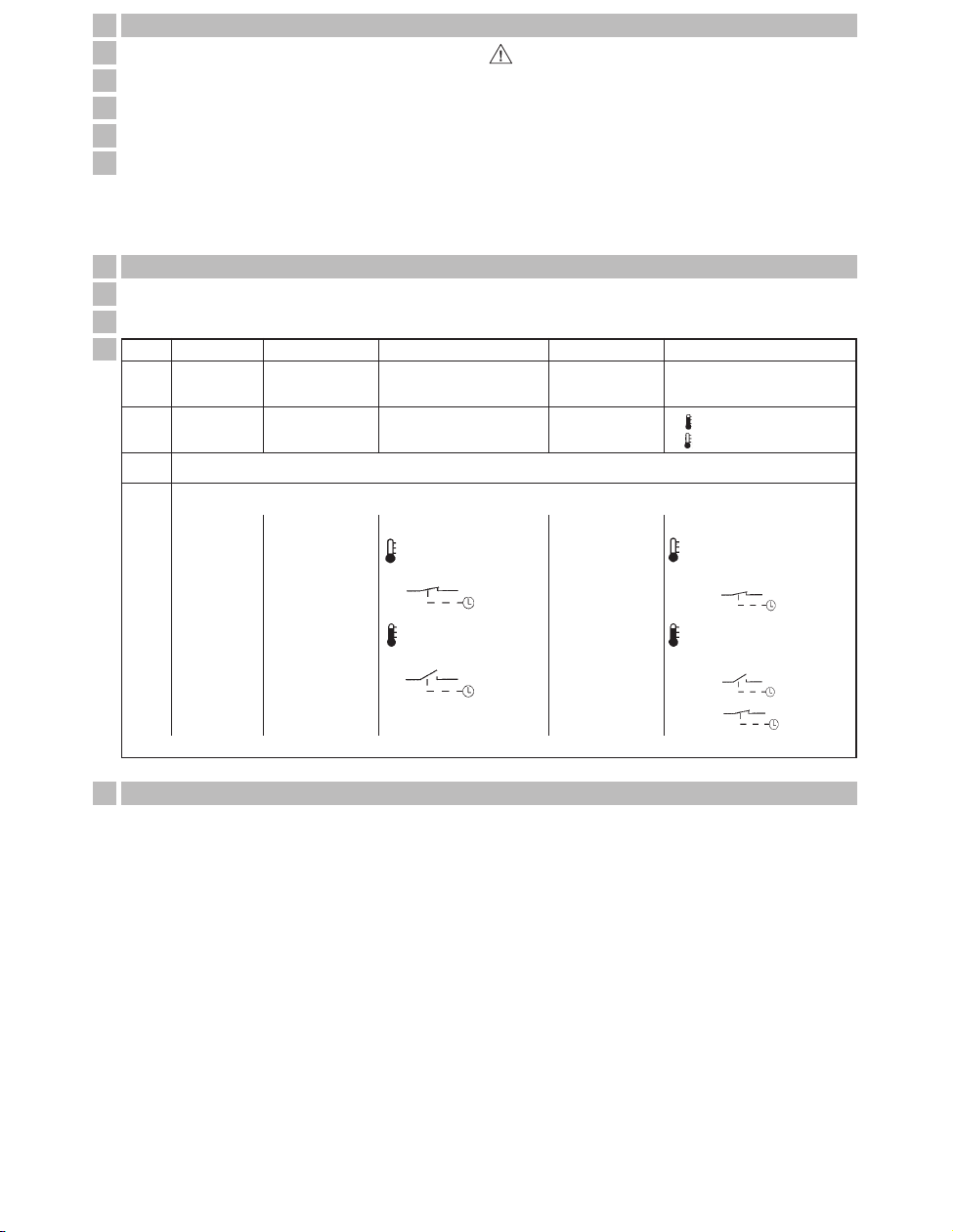
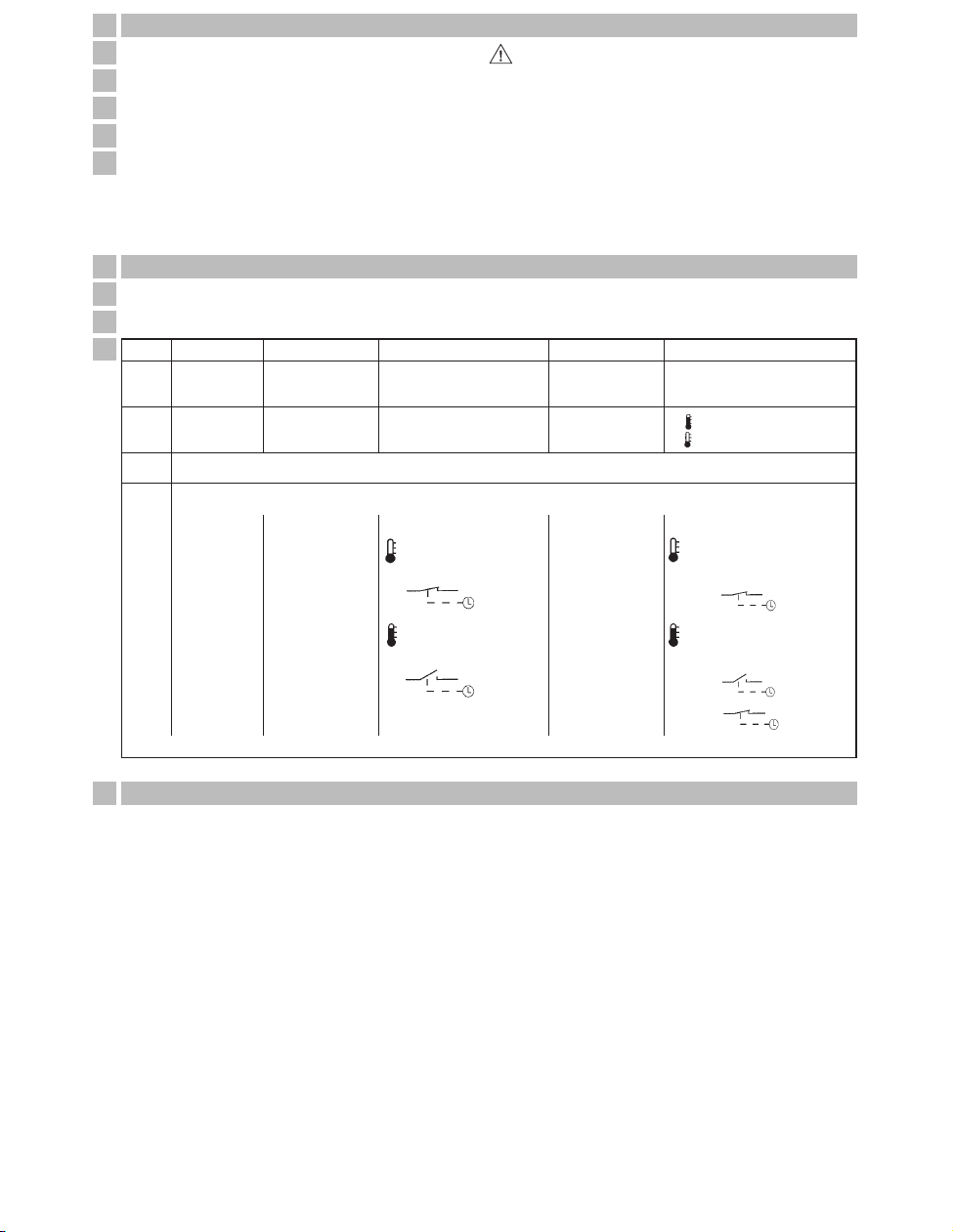
Technische Daten
D
Temperaturbereich festlegen
thermio 102
a)
b)
c)
d)
thermio 402 thermio 103 thermio 403 thermio 513
–– – –
– – Klemme 3 Klemme 3–
LED AUS = Komforttemperatur
LED EIN = Absenktemperatur
––
Temperaturwert einstellen
Anschluß einer Schaltuhr
2 = Komforttemperatur
1 = Absenktemperatur
1 = Heizung EIN
0 = Heizung AUS
1 = Heizung EIN
0 = Heizung AUS
Einstellknopf auf Achse aufstecken. Markierungen beachten!
thermio 102
75 x 71 x 21
2-Draht
ca. 200 mW
0,5/5 A/250 V~
0,5/4 A/250 V~
0,5/1 A/24 V–
Öffner bei steigender Temperatur
Ag Ni
T 30
II nach entspr. Montage
–
–
–
Aufputz
Schraubklemme mit Drahtschutz
+5 °C bis +30 °C
–
ca. 1 K
thermisch
-20 °C bis +70 °C
IP 20
nach EN 55014
Maße H x B x T mm
Gewicht
Anschluß
Leistungsaufnahme
Schaltleistung
- bei ohmscher Last
- bei induktive Last cos. ϕ 0,6
- minimal
Schaltausgang
Schaltkontakte
Umgebungstemperatur
Schutzklasse
Schaltzustands-Anzeige
- Regler
- Wahlschalter
Montageart
Anschlußart
Tagtemperaturregelbereich
Nachtabsenkung
Temperaturschaltdifferenz
Rückführung
Lagertemperatur
Schutzart
Funkentstörung
thermio 402
75 x 71 x 21
2-Draht
ca. 200 mW
0,5/5 A/250 V~
0,5/4 A/250 V~
0,5/1 A/24 V–
Öffner bei steigender Temperatur
Ag Ni
T 30
II nach entspr. Montage
ja
–
Heizung Ein/Aus
Aufputz
Schraubklemme mit Drahtschutz
+5 °C bis +30 °C
–
ca. 1 K
thermisch
-20 °C bis +70 °C
IP 20
nach EN 55014
thermio 103
75 x 71 x 21
3-Draht
ca. 200 mW
10 A/250 V~
4 A/250 V~
0,1 A/230 V–
Öffner bei steigender Temperatur
Ag Ni
T 30
II nach entspr. Montage
–
–
–
Aufputz
Schraubklemme mit Drahtschutz
+5 °C bis +30 °C
ca. 4 K
ca. 0,5 K
thermisch
-20 °C bis +70 °C
IP 20
nach EN 55014
thermio 403
75 x 71 x 21
3-Draht
ca. 200 mW
10 A/250 V~
4 A/250 V~
0,1 A/230 V–
Öffner bei steigender Temperatur
Ag Ni
T 30
II nach entspr. Montage
ja
–
Heizung Ein/Aus
Aufputz
Schraubklemme mit Drahtschutz
+5 °C bis +30 °C
–
ca. 0,5 K
thermisch
-20 °C bis +70 °C
IP 20
nach EN 55014
thermio 513
75 x 71 x 21
3-Draht
ca. 200 mW
10 A/250 V~
4 A/250 V~
0,1 A/230 V–
Öffner bei steigender Temperatur
Ag Ni
T 30
II nach entspr. Montage
ja
LED grün
Nachtabsenkung Ein/Aus
Aufputz
Schraubklemme mit Drahtschutz
+5 °C bis +30 °C
ca. 4 K
ca. 0,5 K
thermisch
-20 °C bis +70 °C
IP 20
nach EN 55014
Absenktemperatur EIN
Raumtemperatur einstellen
z. B. 22 °C
=
^
18°C
Absenktemperatur AUS
Raumtemperatur einstellen
z. B. 22 °C
=
^
22°C
EIN
AUS
Absenktemperatur EIN
Raumtemperatur einstellen
z. B.22 °C
LED EIN +
=
^
18°C
Absenktemperatur AUS
Raumtemperatur einstellen
z. B.22 °C
LED AUS +
=
^
22°C
LED AUS +
=
^
22°C
EIN
AUS
EIN
* Absenktemperatur = Komforttemperatur minus 4° (Kelvin)
Page 3
1
2
3
4
Assembly/Installation
GB
Lift the adjusting knob with a suitable tool
Release the fastening screw
Remove the upper part of the case
Determine the appropriate type of installation
5
– The unit must be connected by a qualified person exercising
due care
– Switch off the heating system before assembly
– Check and make sure that the connecting wires are not
live
–
Guide the connecting wires through the opening in the unit’s base
– Mount the base on a flat, firm surface or flush-mounted socket
–
Strip the connection wires properly and connect as shown in
the circuit diagram, see the circuit diagrams on the following
pages
Accuracy of control is only achieved if the stated current
values are adhered to.
Do you know how much current is drawn by the consumer?
If in doubt, check!
Select the right type of connection terminals when making the
connection!
6
7
8
Connection/Operation
GB
Technical data
GB
Determine the temperature range
thermio 102
a)
b)
c)
d)
thermio 402 thermio 103 thermio 403 thermio 513
–– – –
– – Connect terminal 3 Connect terminal 3–
LED OFF =
Comfort temperature
LED ON =
Lower temperature
––
Set temperature value
Connection of a time switch
2 =
Comfort temperature
1 =
Lower temperature
1=
Heating ON
0=
Heating OFF
1=
Heating ON
0=
Heating OFF
Put the setting knob on the shaf. Note the markings!
thermio 102
75 x 71 x 21
2-wire
approx. 200 mW
0,5/5 A/250 V~
0,5/4 A/250 V~
0,5/1 A/24 V–
Opens (with increasing temperature)
Ag Ni
T 30
II after suitable installation
–
–
–
Surface mounting
Screw terminal with wire fuse
+5 °C to +30 °C
–
approx. 1 K
Thermal
-20 °C to +70 °C
IP 20
as per EN 55014
Dimensions H x W x D mm
Weight g (approx.)
Connection
Power consumption
Switching capacity
- with ohmic load
-
with inductive load cos. ϕ 0,6
- minimum
Switching output
Switching contact
Ambient temperature
Protection class
Switching status indication
- thermostat
- selector switch
Type of installation
Type of connection
Day temperature regulation range
Overnight temperature drop
Temperature switching differential
Feedback
Storage temperature
Type of protection
Radio interference suppression
thermio 402
75 x 71 x 21
2-wire
approx. 200 mW
0,5/5 A/250 V~
0,5/4 A/250 V~
0,5/1 A/24 V–
Opens (with increasing temperature)
Ag Ni
T 30
II after suitable installation
yes
–
Heating On/Off
Surface mounting
Screw terminal with wire fuse
+5 °C to +30 °C
–
approx. 1 K
Thermal
-20 °C to +70 °C
IP 20
as per EN 55014
thermio 103
75 x 71 x 21
3-wire
approx. 200 mW
10 A/250 V~
4 A/250 V~
0,1 A/230 V–
Opens (with increasing temperature)
Ag Ni
T 30
II after suitable installation
–
–
–
Surface mounting
Screw terminal with wire fuse
+5 °C to +30 °C
approx. 4 K
approx. 0,5 K
Thermal
-20 °C to +70 °C
IP 20
as per EN 55014
thermio 403
75 x 71 x 21
3-wire
approx. 200 mW
10 A/250 V~
4 A/250 V~
0,1 A/230 V–
Opens (with increasing temperature)
Ag Ni
T 30
II after suitable installation
yes
–
Heating On/Off
Surface mounting
Screw terminal with wire fuse
+5 °C to +30 °C
–
approx. 0,5 K
Thermal
-20 °C to +70 °C
IP 20
as per EN 55014
thermio 513
75 x 71 x 21
3-wire
approx. 200 mW
10 A/250 V~
4 A/250 V~
0,1 A/230 V–
Opens (with increasing temperature)
Ag Ni
T 30
II after suitable installation
yes
LED green
Overnight temperature drop On/Off
Surface mounting
Screw terminal with wire fuse
+5 °C to +30 °C
approx. 4 K
approx. 0,5 K
Thermal
-20 °C to +70 °C
IP 20
as per EN 55014
Lower temperature O
N
Set the room temperature
e. g. 22 °C
=
^
18°C
Lower temperature OFF
Set the room temperature
e. g. 22 °C
=
^
22°C
ON
OFF
Lower temperature O
N
Set the room temperature
e. g.22 °C
LED ON +
=
^
18°C
Lower temperature OFF
Set the room temperature
e. g.22 °C
LED OFF +
=
^
22°C
LED OFF +
=
^
22°C
ON
OFF
ON
* Lower temperature = Comfort temperature minus 4 K (Kelvin)
Page 4

1
2
3
4
Montage/Installation
F
Soulever le bouton de réglage avec un outil adéquate
Dévisser la vis de serrage
Soulever le capot de l’appareil
Définir l’endroit d’installation adapté
5
–
Le montage/installation doit être réalisé(e) avec soin par
un spécialiste.
–
Avant le commencer le montage il faut couper l’installation électrique
– Vérifier et s’assurer que les fils de raccordement ne sont pas
sous tension.
–
Passer les câbles de raccordement au travers de l’ouverture
dans le socle de l’appareil.
–
Fixer le socle sur une base solide ou sur un boîtier de raccordement
–
Séparer les fils à raccorder. Connecter les fils suivant le
schéma de montage figurant sur les pages suivantes.
La précision de réglage ne sera atteinte que si la consommation est respectée.
Connaissez-vous la consommation de l’utilisateur?
En cas de doute vérifiez la!
Nous recommandons un appareil avec réglage électronique
pour branchement 2 fils.
6
7
8
Raccordement/Fonctionnement
F
Caractéristiques techniques
F
Régler, définir la zone de température
thermio 102
a)
b)
c)
d)
thermio 402 thermio 103 thermio 403 thermio 513
–– – –
– – Contact 3 Contact 3–
LED OFF = temp. confort
LED ON = temp. réduite
––
Régler la valéur de température
Raccordement d’une horloge
2 =
temp. confort
1 =
temp. réduite
1=
Chauffage ON
0=
Chauffage OFF
1=
Chauffage ON
0=
Chauffage OFF
Mettre le bouton de réglage sur l’axe. Respecter les marques!
thermio 102
75 x 71 x 21
2 fils
environ 200 mW
0,5/5 A/250 V~
0,5/4 A/250 V~
0,5/1 A/24 V–
ouverture quand la température augmente
Ag Ni
T 30
II suivant montage
–
–
–
en saillie sans socle
avec bornes à vis
+5 °C à +30 °C
–
env. 1 K
thermique
-20 °C à +70 °C
IP 20
suivant EN 55014
Dimensions h x l x p mm
Poids en g (env.)
Raccordement
Consommation
Pouvoir de coupure
– charge ohmique
–
charge inductive cos. ϕ 0,6
– minimal
Contact de sortie
Contact
Temp. de fonctionnement
Classe de protection
Indicateur de l’état du contact
– régulateur
– sélecteur
Type de montage
Type de raccordement
Plage de réglage des temp.
Abaissement réduit
Différentiel de temp.
Asservissement
Temp. de fonctionnement
Type de protection
Perturbations
thermio 402
75 x 71 x 21
2 fils
environ 200 mW
0,5/5 A/250 V~
0,5/4 A/250 V~
0,5/1 A/24 V–
ouverture quand la température augmente
Ag Ni
T 30
II suivant montage
oui
–
abaissement EN/HORS
en saillie sans socle
avec bornes à vis
+5 °C à +30 °C
–
env. 1 K
thermique
-20 °C à +70 °C
IP 20
suivant EN 55014
thermio 103
75 x 71 x 21
3 fils
environ 200 mW
10 A/250 V~
4 A/250 V~
0,1 A/230 V–
ouverture quand la température augmente
Ag Ni
T 30
II suivant montage
–
–
–
en saillie sans socle
avec bornes à vis
+5 °C à +30 °C
env. 4 K
env. 0,5 K
thermique
-20 °C à +70 °C
IP 20
suivant EN 55014
thermio 403
75 x 71 x 21
3 fils
environ 200 mW
10 A/250 V~
4 A/250 V~
0,1 A/230 V–
ouverture quand la température augmente
Ag Ni
T 30
II suivant montage
oui
–
abaissement EN/HORS
en saillie sans socle
avec bornes à vis
+5 °C à +30 °C
–
env. 0,5 K
thermique
-20 °C à +70 °C
IP 20
suivant EN 55014
thermio 513
75 x 71 x 21
3 fils
environ 200 mW
10 A/250 V~
4 A/250 V~
0,1 A/230 V–
ouverture quand la température augmente
Ag Ni
T 30
II suivant montage
oui
symbole diode vert
abaissement EN/HORS
en saillie sans socle
avec bornes à vis
+5 °C à +30 °C
env. 4 K
env. 0,5 K
thermique
-20 °C à +70 °C
IP 20
suivant EN 55014
Temp. réduite ON
Régler la température
ex. 22°C
=
^
18°C
Absenktemperatur AUS
Raumtemperatur einstellen
ex. 22°C
=
^
22°C
ON
OFF
Temp. réduite ON
Régler la température
ex. 22°C
LED ON +
=
^
18°C
Temp. réduite OFF
Régler la température
ex. 22°C
LED OFF +
=
^
22°C
LED OFF +
=
^
22°C
ON
OFF
ON
* Température réduite = température confort moins 4°
Page 5

1
2
3
4
Installazione
I
Estraete la manopola di regolazione del termostato con un utensile adeguato
Svitate la vite di fissaggio (parte superiore-parte inferiore)
Togliete la parte superiore della custodia
Installate l’apparecchio in una posizione adeguata
5
L’installazione deve essere effettuata da personale professionalmente qualificato
–
Prima di installare il termostato spegnete l’impianto di riscaldamento e
disinserite l’interruttore di comando dell’impianto elettrico.
–
Verificate e accertateVi che i fili di collegamento non siano sotto tensione.
– Fate passare i fili attraverso le aperture poste alla base del
termostato.
– Installate la base su un piano stabile
–
Isolate i fili di collegamento a regola d’arte e collegateli secondo il relativo
schema elettrico, vedi etichetta adesiva posta sull’apparecchio.
La precisione nella regolazione viene raggiunta solo se si
mantiene il minimo della corrente assorbita indicata.
Se non conoscete l’assorbimento di corrente dell’apparecchio
utilizzatore (es. caldaia) verificatelo prima di procedere
all’installazione del termostato.
Controllate che il collegamento elettrico sia stato effettuato ai
morsetti appropriati!
6
7
8
Istruzioni di funzionamento
I
Dati tecnici
I
Stabilite l’ambito di temperatura
thermio 102
a)
b)
c)
d)
thermio 402 thermio 103 thermio 403 thermio 513
–– – –
– – Morsetto 3 Morsetto 3–
LED SPENTO = Temperatura di comfort
LED ACCESO = Temperatura ridotta
––
Impostare i valori di temperatura
Collegamento di un programmatore orario
2 = Temperatura di comfort
1 = Temperatura ridotta
1 =Riscaldamento ACCESO
0 =Ridcaldamento SPENTO
1 =Riscaldamento ACCESO
0 =Ridcaldamento SPENTO
Inserite la manopola di regolazione in corrispondenza del riferimento posto sul perno di regolazione del termostato
thermio 102
75 x 71 x 21
2 fili
ca. 200 mW
0,5/5 A/250 V~
0,5/4 A/250 V~
0,5/1 A/24 V–
aperta con temperatura in aumento
Ag Ni
T 30
II dopo il relativo montaggio
nessuna
–
–
a parete
morsetto a vite con protezione del filo
da +5 °C a +30 °C
–
ca. 1 K
termica
da -20 °C a +70 °C
IP 20
secondo EN 55014
Dimensioni H x I x P mm
Peso
Collegamento
Corrente assorbita
Portata contatti
- carico ohmico
- carico induttivo cos ϕ 0,6
- minima
Uscita
Tipo contatti
Temperatura ambiente
Classe di protezione
Indicazione stato di comando
- regolazione
- selettore
Tipo di montaggio
Tipo di collegamento
Campo di regolazione temperatura
Abbassamento notturno
Campo di intervento temperatura
Controreazione
Temperatura di immagazzinaggia
Tipo di protezione
Schermatura contro i radiodisturbi
thermio 402
75 x 71 x 21
2 fili
ca. 200 mW
0,5/5 A/250 V~
0,5/4 A/250 V~
0,5/1 A/24 V–
aperta con temperatura in aumento
Ag Ni
T 30
II dopo il relativo montaggio
si
–
Riscaldamento ON/OFF
a parete
morsetto a vite con protezione del filo
da +5 °C a +30 °C
–
ca. 1 K
termica
da -20 °C a +70 °C
IP 20
secondo EN 55014
thermio 103
75 x 71 x 21
3 fili
ca. 200 mW
10 A/250 V~
4 A/250 V~
0,1 A/230 V–
aperta con temperatura in aumento
Ag Ni
T 30
II dopo il relativo montaggio
nessuna
–
–
a parete
morsetto a vite con protezione del filo
da +5 °C a +30 °C
ca. 4 K
ca. 0,5 K
termica
da -20 °C a +70 °C
IP 20
secondo EN 55014
thermio 403
75 x 71 x 21
3 fili
ca. 200 mW
10 A/250 V~
4 A/250 V~
0,1 A/230 V–
aperta con temperatura in aumento
Ag Ni
T 30
II dopo il relativo montaggio
si
–
Riscaldamento ON/OFF
a parete
morsetto a vite con protezione del filo
da +5 °C a +30 °C
–
ca. 0,5 K
termica
da -20 °C a +70 °C
IP 20
secondo EN 55014
thermio 513
75 x 71 x 21
3 fili
ca. 200 mW
10 A/250 V~
4 A/250 V~
0,1 A/230 V–
aperta con temperatura in aumento
Ag Ni
T 30
II dopo il relativo montaggio
si
LED verde
Abbassamento notturno ON/OFF
a parete
morsetto a vite con protezione del filo
da +5 °C a +30 °C
ca. 4 K
ca. 0,5 K
termica
da -20 °C a +70 °C
IP 20
secondo EN 55014
Riduzione di temp. attiva
Impostare la temp. ambiente
p. es. 22°C
=
^
18°C
Riduzione di temperatura
inattiva
p. es. 22°C
=
^
22°C
ON
OFF
Riduzione di temp. attiva
Impostare la temp. ambiente
p. es. 22°C
LED ON +
=
^
18°C
Riduzione di temperatura
inattiva – Impostare la temp. ambiente
p. es. 22°C
LED OFF +
=
^
22°C
LED OFF +
=
^
22°C
EIN
OFF
ON
* Temperatura ridotta = Temperatura di comfort meno 4° (Kelvin)
Page 6

1
2
3
4
Montaje/conexión
E
Levante la rueda de ajuste con la herramienta apropiada
Saque el tornillo de cierre
Levante la parte superior de la carcasa
Busque un lugar apropiado para su colocación
5
–
La conexión de la unidad debe realizarla personal
cualificado
–
Apague el sistema de calefacción antes de colocar el aparato
–
Compruebe y asegúrese que los cables de conexión no
están bajo tensión
–
Introduzca los cables por la apertura de la base de la unidad
– Coloque la base sobre una superficie lisa y firme o sobre una
caja de mecanismo
–
Pele los cable de conexión y conectelos según se indica en los
diagramas eléctricos que se muestran el las páginas siguientes
Solo se puede conseguir la máxima precisión de control si los
valor de corriente son ajustados.
¿Sabe cuanta corriente se va a consumir?
Si no está seguro, compruébelo!
Elija los terminales apropiados para realizar la conexión.
6
7
8
Montaje/conexión
E
Datos técnicos
E
Determine el rango de temperaturas
thermio 102
a)
b)
c)
d)
thermio 402 thermio 103 thermio 403 thermio 513
–– – –
– – terminale 3 terminale 3–
LED apagado = Temperatura de confort
LED encendido = Temperatura de ahorro
––
Ajustar los valores de temperatura
Conexión de un interruptor horario
2 =
Temperatura de confort
1 =
Temperatura de ahorro
1=
Calefacción encendida
0=
Calefacción apagada
1=
Calefacción encendida
0=
Calefacción apagada
Coloque la rueda de ajuste en su sitio atendiendo a los topes.
thermio 102
75 x 71 x 21
2 hilos
aprox. 200 mW
0,5/5 A/250 V~
0,5/4 A/250 V~
0,5/1 A/24 V–
Abre al subir la temperatura
Ag Ni
T 30
II tras una instalación correcta
–
–
–
Montaje en superficie
Terminales de tornillo con hilo fusible
+5 °C a +30 °C
–
aprox. 1 K
Térmica
-20 °C a +70 °C
IP 20
Ségun EN 55014
Dimensíones A x A x P mm
Peso (aprox.)
Conexión
Consumo
Capacidad de corte
- con carga óhmica
-
con carga inductiva (cos. ϕ 0,6)
- carga mínima
Salida
Contactos de salida
Temperatura ambiente
Clase de protección
Indicación de estado
- Termostato
- Interruptor de selección
Forma de instalación
Forma de conexión
Rango de temperaturas de regulación
Bajada de temperatura nocturna
Diferencial de temperatura de conmutación
Realimentación
Temperatura de almacenamiento
Grado de protección
Supresor de interferencias de radio
thermio 402
75 x 71 x 21
2 hilos
aprox. 200 mW
0,5/5 A/250 V~
0,5/4 A/250 V~
0,5/1 A/24 V–
Abre al subir la temperatura
Ag Ni
T 30
II tras una instalación correcta
si
–
Calefacción ON/OFF
Montaje en superficie
Terminales de tornillo con hilo fusible
+5 °C a +30 °C
–
aprox. 1 K
Térmica
-20 °C a +70 °C
IP 20
Ségun EN 55014
thermio 103
75 x 71 x 21
3 hilos
aprox. 200 mW
10 A/250 V~
4 A/250 V~
0,1 A/230 V–
Abre al subir la temperatura
Ag Ni
T 30
II tras una instalación correcta
–
–
–
Montaje en superficie
Terminales de tornillo con hilo fusible
+5 °C a +30 °C
aprox. 4 K
aprox. 0,5 K
Térmica
-20 °C a +70 °C
IP 20
Ségun EN 55014
thermio 403
75 x 71 x 21
3 hilos
aprox. 200 mW
10 A/250 V~
4 A/250 V~
0,1 A/230 V–
Abre al subir la temperatura
Ag Ni
T 30
II tras una instalación correcta
si
–
Calefacción ON/OFF
Montaje en superficie
Terminales de tornillo con hilo fusible
+5 °C a +30 °C
–
aprox. 0,5 K
Térmica
-20 °C a +70 °C
IP 20
Ségun EN 55014
thermio 513
75 x 71 x 21
3 hilos
aprox. 200 mW
10 A/250 V~
4 A/250 V~
0,1 A/230 V–
Abre al subir la temperatura
Ag Ni
T 30
II tras una instalación correcta
ja
LED verde
Bajada de temperatura nocturna ON/OFF
Montaje en superficie
Terminales de tornillo con hilo fusible
+5 °C a +30 °C
aprox. 4 K
aprox. 0,5 K
Térmica
-20 °C a +70 °C
IP 20
Ségun EN 55014
Temperatura de ahorro activada
Seleccione la temperatura de la habitación
ejem.
.22°C
=
^
18°C
Temperatura de ahorro desactivada
Seleccione la temperatura de la habitación
ejem.
.22°C
=
^
22°C
Encendido
Apagado
Temperatura de ahorro activada
Seleccione la temperatura de la habitación
ejem.
22°C
LED +
=
^
18°C
Temperatura de ahorro desactivada
Seleccione la temperatura de la habitación
ejem
.22°C
LED +
=
^
22°C
LED +
=
^
22°C
Encendido
Apagado
Encendido
* Temperatura a ahorro = temperatura de confort – 4° K (kelvin)
Page 7

1
2
3
4
Montage
NL
Instelknop met een daarvoor bestemd gereedschap verwijderen
Bevestigingsschroeven verwijderen
Bovendeel behuizing wegnemen
Geschikte montageplaats bepalen
5
–
De montage/aansluting moet door een vakman met
zorgvuldigheid uitgevoerd worden.
–
Voor de montage verwarming uitschakelen
–
Controleren en zekerstellen dat de aansluitdraden geen
spanning meer voeren
–
Aansluitingen door de opening in de sokkel van het apparaat steken
–
Sokkel op een stevige ondergrond of een UP-doos monteren
–
Aansluitdraden vakbekwaam isoleren en het schakelbeeld
bevoegd aansluiten, zie schakelbeelden op de volgende pagina
De regelnauwkeurigheid wordt alleen bereikt, als de aangegeven stroomopname gehanteerd word.
Kent u de stroomopname van de verbruiker?
In twijfelgevallen controleren!
Kies bij montage de juiste aansluitklem.
6
7
8
Bediening
NL
Technische gegevens
NL
Temperatuurbereik vastleggen
thermio 102
a)
b)
c)
d)
thermio 402 thermio 103 thermio 403 thermio 513
–– – –
– – Klem 3 Klem 3–
LED Uit = comforttemperatuur
LED Aan = dalingstemperatuur
––
Temperatuurwarde instellen
Aansluiten van een schakelklok
2 =
comforttemperatuur
1 =
dalingstemperatuur
1=
Verwarming Aan
0=
Verwarming Uit
1=
Verwarming Aan
0=
Verwarming Uit
Instelknop op as bevestigen. Markering in acht nemen!
thermio 102
75 x 71 x 21
2-draads
ca. 200 mW
0,5/5 A/250 V~
0,5/4 A/250 V~
0,5/1 A/24 V–
opent bij stijgende temperatuur
Ag Ni
T 30
II na zorgvuldige montage
–
–
–
opbouw
schroefklemmen met draadbescherming
+5 °C tot +30 °C
–
ca. 1 K
thermisch
-20 °C tot +70 °C
IP 20
volgens EN 55014
Grootte H x B x D mm
Gewicht gr. (ca.)
Aansluiting
Vermogensopname
Schakelvermogen
- bij ohmse belasting
-
bij induktieve belasting cos. ϕ 0,6
- minimaal
Schakeluitgang
Schakelkontakt
Omgevingstemperatuur
Beschermingsklasse
Aanduiding schakeltoestand
- regelaar
- keuzeschakelaar
Montage
Aansluiting
Dagtemperatuurregelbereik
Nachtdaling
Temperatuurschakeldifferentie
Terugkoppeling
Magazijntemperatuur
Bescherming
Antenne-ontstoring
thermio 402
75 x 71 x 21
2-draads
ca. 200 mW
0,5/5 A/250 V~
0,5/4 A/250 V~
0,5/1 A/24 V–
opent bij stijgende temperatuur
Ag Ni
T 30
II na zorgvuldige montage
ja
–
verwarming AAN/UIT
opbouw
schroefklemmen met draadbescherming
+5 °C tot +30 °C
–
ca. 1 K
thermisch
-20 °C tot +70 °C
IP 20
volgens EN 55014
thermio 103
75 x 71 x 21
3-draads
ca. 200 mW
10 A/250 V~
4 A/250 V~
0,1 A/230 V–
opent bij stijgende temperatuur
Ag Ni
T 30
II na zorgvuldige montage
–
–
–
opbouw
schroefklemmen met draadbescherming
+5 °C tot +30 °C
ca. 4 K
ca. 0,5 K
thermisch
-20 °C tot +70 °C
IP 20
volgens EN 55014
thermio 403
75 x 71 x 21
3-draads
ca. 200 mW
10 A/250 V~
4 A/250 V~
0,1 A/230 V–
opent bij stijgende temperatuur
Ag Ni
T 30
II na zorgvuldige montage
ja
–
verwarming AAN/UIT
opbouw
schroefklemmen met draadbescherming
+5 °C tot +30 °C
–
ca. 0,5 K
thermisch
-20 °C tot +70 °C
IP 20
volgens EN 55014
thermio 513
75 x 71 x 21
3-draads
ca. 200 mW
10 A/250 V~
4 A/250 V~
0,1 A/230 V–
opent bij stijgende temperatuur
Ag Ni
T 30
II na zorgvuldige montage
ja
LED groen
nachtdaling AAN/UIT
opbouw
schroefklemmen met draadbescherming
+5 °C tot +30 °C
ca. 4 K
ca. 0,5 K
thermisch
-20 °C tot +70 °C
IP 20
volgens EN 55014
Dalingstemperatuur Aan
Kamertemperatuur instellen
bijv. 22 °C
=
^
18°C
Dalingstemperatuur Uit
Kamertemperatuur instellen
bijv. 22 °C
=
^
22°C
Aan
Uit
Dalingstemperatuur Aan
Kamertemperatuur instellen
bijv.
22°C
LED Aan
+
=
^
18°C
Dalingstemperatuur Uit
Kamertemperatuur instellen
bijv.
22°C
LED Uit
+
=
^
22°C
LED Uit
+
=
^
22°C
Aan
Uit
Aan
* Dalingstemperatuur = comforttemperatuur minus 4° (Kelvin)
Page 8

1
2
3
4
Szerelés/telepítés
H
A beállító gombot megfelelő szerszámmal le kell emelni
A rögzítő csavart ki kell csavarni
A ház felső részét le kell venni
A szerelésre megfelelő helyet meg kell határozni
5
–
A csatlakoztatást hozzáértő szakembernek megfelelő
gondossággal kell elvégeznie
–
A szerelés előtt ki kell kapcsolni a fűtőberendezést
–
Ellenőrizni és biztosítani kell, hogy a csatlakozó
huzalok ne álljanak feszültség alatt
–
A csatlakozó vezetékeket át kell vezetni a készülék aljzatának nyílásán.
–
A foglalatot szilárd, sík alapra vagy süllyesztett dobozba kell szerelni
–
A csatlakozó huzalokatszakszerűen kell lecsupaszítani
és a kapcsolási rajznak megfelelően kell bekötni, ld. a
további oldalak kapcsolási rajzait
A szabályozási pontosságot csak akkor érhetjük el, ha a
mega-dott áramfelvételt betartjuk. Ismeri a fogyasztó
áramfelvételét?
Kétség esetén mérje meg!
Csatlakoztatáskor a megfelelő csatlakoztató kapcsot
válassza!
6
7
8
Csatlakoztatás/kezelés
H
Műszaki adatok
H
A hőmérséklettartomány meghatározása
thermio 102
a)
b)
c)
d)
thermio 402 thermio 103 thermio 403 thermio 513
–– – –
– – Kapoc 3 Kapoc 3–
LED kikapcsolva = komfort hőmérséklet
LED bekapcsolva = lecsökkentett hőmérséklet
––
Hömérsékleti értéket beállítani
Kapcsolóóra csatlakoztatása
2 =
lecsökkentett hőmérséklet
1 =
komfort hőmérséklet
1=
Fűtés be
0=
Fűtés ki
1=
Fűtés be
0=
Fűtés ki
A beállító gomb felültetése a tengelyre. Ügyeljünk a jelölésekre!
thermio 102
75 x 71 x 21
2 vezetékes
kb.
200 mW
0,5/5 A/250 V~
0,5/4 A/250 V~
0,5/1 A/24 V–
Érintkező nyitás (növekvő hőmérséklet esetén)
Ag Ni
T 30
II, megfelelő szerelés után
–
–
–
Vakolat fölötti szerelés
+5
-tól
+30
˚C-ig
–
kb.
1 K
termikus
-20-tól +70˚C-ig
IP 20
az EN 55014 szerint
Mért H x SZ x M mm
Súly g (kb)
Csatlakozás
Teljesítményfelvétel
Kapcsolási teljesítmény
- ohmos terhelés esetén
-
induktív terhelés esetén cos ϕ 0,6
- minimálisan
Kapcsoló kimenet
Kapcsolóérintkezők
Környezeti hőmérséklet
Védelmi osztály
Kapcsolóállapot jelzés
- szabályozó
- választókapcsoló
Szerelési mód
Napi hőmérsékletszabályozási tart.
Éjszakai hőmérsékletcsökkenés
Kapcsolási hőmérséklet különbsége
Visszacsatolás
Raktározási hőmérséklet
Védettség
Rádió zavarszűrés
thermio 402
75 x 71 x 21
2
vezetékes
kb.
200 mW
0,5/5 A/250 V~
0,5/4 A/250 V~
0,5/1 A/24 V–
Érintkező nyitás (növekvő hőmérséklet esetén)
Ag Ni
T 30
II, megfelelő szerelés után
igen
–
Fűtés be/ki
Vakolat fölötti szerelés
+5
-tól
+30
˚C-ig
–
kb.
1 K
termikus
-20-tól +70˚C-ig
IP 20
az EN 55014 szerint
thermio 103
75 x 71 x 21
3
vezetékes
kb.
200 mW
10 A/250 V~
4 A/250 V~
0,1 A/230 V–
Érintkező nyitás (növekvő hőmérséklet esetén)
Ag Ni
T 30
II, megfelelő szerelés után
–
–
–
Vakolat fölötti szerelés
+5
-tól
+30
˚C-ig
kb.
4 K
kb.
0,5 K
termikus
-20-tól +70˚C-ig
IP 20
az EN 55014 szerint
thermio 403
75 x 71 x 21
3
vezetékes
kb.
200 mW
10 A/250 V~
4 A/250 V~
0,1 A/230 V–
Érintkező nyitás (növekvő hőmérséklet esetén)
Ag Ni
T 30
II, megfelelő szerelés után
igen
–
Fűtés be/ki
Vakolat fölötti szerelés
+5
-tól
+30
˚C-ig
–
kb.
0,5 K
termikus
-20-tól +70˚C-ig
IP 20
az EN 55014 szerint
thermio 513
75 x 71 x 21
3
vezetékes
kb.
200 mW
10 A/250 V~
4 A/250 V~
0,1 A/230 V–
Érintkező nyitás (növekvő hőmérséklet esetén)
Ag Ni
T 30
II, megfelelő szerelés után
igen
LED grün
éjszakai hőmérsékletcsökkentés be/ki
Vakolat fölötti szerelés
+5
-tól
+30
˚C-ig
kb.
4 K
kb.
0,5 K
termikus
-20-tól +70˚C-ig
IP 20
az EN 55014 szerint
Lecsökkentett hőmérséklet bekapcsolása
Szobahőmérséklet beállítása
pl. 22˚C
LED bekapcsolva
=
^
18˚C
Lecsökkentett hőmérséklet kikapcsolása
szobahőmérséklet beállítása
pl. 22˚C
LED kikapcsolva
=
^
22˚C
Lecsökkentett hőmérséklet bekapcsolása
Szobahőmérséklet beállítása
pl. 22˚C
LED bekapcsolva
=
^
18˚C
Lecsökkentett hőmérséklet kikapcsolása
szobahőmérséklet beállítása
pl. 22˚C
LED kikapcsolva
=
^
22˚C
LED kikapcsolva
=
^
22˚C
* Lecsökkentett hőmérséklet = Komfort hőmérséklet mínusz 4˚ (Kelvin)
Page 9

1
2
3
4
Montaż/Instalacja
PL
Pokrętło temperatury podważyć i wyjąć z obudowy regulatora
Odblokować zapadki we wskazanych miejscach
Zdjąć górną część obudowy
Wybrać odpowiednie miejsce do zamontowania urządzenia
5
–
Montaż musi być przeprowadzony przez fachowca
–
Przed montazem wyłączyć ogrzewanie
–
Sprawdzić czy przewody nie są pod napięciem.
–
Przewody połączeniowe poprowadzić przez otwory w
ramce urządzenia
–
Ramkę zamontować na pewnym, równym i suchym
podłożu lub na puszce elektrycznej
– Zdająć izolację z przewodów podłączyć je zgodnie ze
schematem (patrz str. 7)
Regulator będzie prawidłowo funkcjonował tylko w
przypadku kiedy płynący prąd przez jego styki będzie
większy od 0,5 A.
Jeżeli pobór prądu jest < 0,5 A, proponujemy urządzenie z
elektronicznym regulatorem dła połączeń 2-przewodowych.
6
7
8
Podłączenie/obsługa
PL
Dane technicane
PL
Ustalić zakres temperatur
thermio 102
a)
b)
c)
d)
thermio 402 thermio 103 thermio 403 thermio 513
–– – –
– – Zaciski 3 Zaciski 3–
Dioda LED wył = temperatura komfortowa
Dioda LED zał. = temp. obniżona
––
Nastawić temperaturę
Podłączanie wyłącznika zegarowego
2 =
temp. obniżoną
1 =
temp. komfortową
1=
Ogrzewanie włączone
0=
Ogrzewanie wyłączone
1=
Ogrzewanie włączone
0=
Ogrzewanie wyłączone
Pokrętło nałożyć na oś regulatora. Uważać na oznaczenia !
thermio 102
75 x 71 x 21
2-przewodowy
ok.
200 mW
0,5/5 A/250 V~
0,5/4 A/250 V~
0,5/1 A/24 V–
przy wzrastającej temp.
Ag Ni
T 30
Klasa II wg odp. montażu
–
–
–
natynkowy
listwa zaciskowa
+5
˚C do
+30
˚C
–
ok.
1 K
termisch
–20 ˚C do +70 ˚C
IP 20
według
EN 55014
Wymiary wys x szer x glęb (w mm)
Waga w gramach (ok.)
Połączenie
Pobór mocy
Obciążalność styków:
- omowa
- indukcyjna
- minimalna
Styki rozwarte
Styki przełączeniowe
Temperatura otoczenia
Klasa zabezpieczenia
Wskażnik stanu
przełącznika
- regulator
- przełącznik wyboru
Sposób montażu
Sposób podłączenía
Zakres regulacji temp. w ciagu dnia
Zabezpieczenie przed mrozem
Róznica przełączania temp.
Temperatura pracy
Sposób zabezpieczenia
Eliminator zakłóceń
thermio 402
75 x 71 x 21
2
-przewodowy
ok.
200 mW
0,5/5 A/250 V~
0,5/4 A/250 V~
0,5/1 A/24 V–
przy wzrastającej temp.
Ag Ni
T 30
Klasa II wg odp. montażu
tak
–
ogrzewanie zał/wył
natynkowy
listwa zaciskowa
+5
˚C do
+30
˚C
–
ok.
1 K
termisch
–20 ˚C do +70 ˚C
IP 20
według
EN 55014
thermio 103
75 x 71 x 21
3
-przewodowy
ok.
200 mW
10 A/250 V~
4 A/250 V~
0,1 A/230 V–
przy wzrastającej temp.
Ag Ni
T 30
Klasa II wg odp. montażu
–
–
–
natynkowy
listwa zaciskowa
+5
˚C do
+30
˚C
kb.
4 K
ok.
0,5 K
termisch
–20 ˚C do +70 ˚C
IP 20
według
EN 55014
thermio 403
75 x 71 x 21
3
-przewodowy
ok.
200 mW
10 A/250 V~
4 A/250 V~
0,1 A/230 V–
przy wzrastającej temp.
Ag Ni
T 30
Klasa II wg odp. montażu
tak
–
ogrzewanie zał/wył
natynkowy
listwa zaciskowa
+5
˚C do
+30
˚C
–
ok.
0,5 K
termisch
–20 ˚C do +70 ˚C
IP 20
według
EN 55014
thermio 513
75 x 71 x 21
3
-przewodowy
ok.
200 mW
10 A/250 V~
4 A/250 V~
0,1 A/230 V–
przy wzrastającej temp.
Ag Ni
T 30
Klasa II wg odp. montażu
tak
LED zielona
nocne obniżenie temp. zał/wył
natynkowy
listwa zaciskowa
+5
˚C do
+30
˚C
ok.
4 K
ok.
0,5 K
termisch
–20 ˚C do +70 ˚C
IP 20
według
EN 55014
Włączenie temp. obniżonej
Ustawić temperaturę
np.22˚C
=
^
18˚C
Wyłączenie temp. obniżonej
Ustawić temperaturę
np.22˚C
=
^
22˚C
Temp. obniżona zał
Ustawić temperaturę
np. 22˚C
LED zał +
=
^
18˚C
Temp. obniżona wył
Ustawić temperaturę
np. 22˚C
LED wył +
=
^
22˚C
LED wył +
=
^
22˚C
* Lecsökkentett hőmérséklet = Komfort hőmérséklet mínusz 4˚ (Kelvin)
zał
wył
zał
zał
wył
Page 10

1
2
3
4
Montáž/instalace
CZ
Pomocí vhodného nástroje vysunout nastavovací knoflík
Povolit upevňovací šrouby
Sejmout horní část skříňky
Určit vhodné místo k montáži
5
– Připojení musí provést odborník s patřičnou pečlivostí
– Před montáží je třeba topný systém vypnout
– Musí se zajistit a vyzkoušet, že připojovací vodiče nemají
žádné napětí
– Připojovací vodiče protáhnout otvorem v soklu přístroje
– Sokl namontovat na pevný rovný podklad nebo na
podomítkovou krabici
–
Připojovací dráty odborně odizolovat a připojit podle
schematu, viz obrázky na následujících stranách
Přesnost regulace bude dosažena pouze tehdy, když bude
dodržen udaný příkon proudu.
Znáte příkon spotřebiče ?
Jste-li na pochybách, ověřte jej!
Při připojování zvolte správné připojovací svorky.
6
7
8
Připojení/obsluha
CZ
Technické údaje
CZ
Stanovit teplotní rozsah
thermio 102
a)
b)
c)
d)
thermio 402 thermio 103 thermio 403 thermio 513
–– – –
– – Svorky 3 Svorky 3–
LED vyp =
komfortní teplota
LED zap = s
nížená teplota
––
Nastavit hodnotú teploty
Připojení spínacích hodin
2 =
sníženou teplotou
1 =
komfortní teplotou
1=
Topení zapnout
0=
Topení vypnout
1=
Topení zapnout
0=
Topení vypnout
Nastavovací knoflík zasunout zpět do otvoru. Dbát na označení!
thermio 102
75 x 71 x 21
2-vodiče
asi
200 mW
0,5/5 A/250 V~
0,5/4 A/250 V~
0,5/1 A/24 V–
rozpíná při rostoucí teplotě
Ag Ni
T 30
II podle montáže
–
–
–
na omítku
chráněná svorkovnice
+5
˚C až+30
˚C
–
asi
1 K
termická
–20 ˚C až+70 ˚C
IP 20
dle EN 55014
Rozměry V x Š x H mm
Váha g (ca.)
Připojení
Příkon
Spínaný výkon
- při ohmické zátěži
-
při induktivní zátěži cos. ϕ 0,6
- minimálně
Spínaný výstup
Kontakt spínače
Teplota okolí
Ochranná třída
Stav spínače – indikace
- regulátor
- přepínač volby
Místo montáže
Způsob připojení
Regulační rozsah teploty
Noční pokles teploty
Teplotní hystereze
Zpětná vazba
Skladovací teplota
Třída ochrany
Radiové odrušení
thermio 402
75 x 71 x 21
2
-vodiče
asi
200 mW
0,5/5 A/250 V~
0,5/4 A/250 V~
0,5/1 A/24 V–
rozpíná při rostoucí teplotě
Ag Ni
T 30
II podle montáže
ja
–
topení zap/vyp
na omítku
chráněná svorkovnice
+5
˚C až+30
˚C
–
asi
1 K
termická
–20 ˚C až+70 ˚C
IP 20
dle EN 55014
thermio 103
75 x 71 x 21
3
-vodiče
asi
200 mW
10 A/250 V~
4 A/250 V~
0,1 A/230 V–
rozpíná při rostoucí teplotě
Ag Ni
T 30
II podle montáže
–
–
–
na omítku
chráněná svorkovnice
+5
˚C až+30
˚C
asi
4 K
asi
0,5 K
termická
–20 ˚C
až
+70 ˚C
IP 20
dle EN 55014
thermio 403
75 x 71 x 21
3
-vodiče
asi
200 mW
10 A/250 V~
4 A/250 V~
0,1 A/230 V–
rozpíná při rostoucí teplotě
Ag Ni
T 30
II podle montáže
ja
–
ogrzewanie zał/wył
na omítku
chráněná svorkovnice
+5
˚C až+30
˚C
–
asi
0,5 K
termická
–20 ˚C
až
+70 ˚C
IP 20
dle EN 55014
thermio 513
75 x 71 x 21
3
-vodiče
asi
200 mW
10 A/250 V~
4 A/250 V~
0,1 A/230 V–
rozpíná při rostoucí teplotě
Ag Ni
T 30
II podle montáže
ja
zelená LED
noční pokles zap/vyp
na omítku
chráněná svorkovnice
+5
˚C až+30
˚C
asi
4 K
asi
0,5 K
termická
–20 ˚C
až
+70 ˚C
IP 20
dle EN 55014
Snížená teplota zapnuta
Nastavit teplotu v místnosti
např.
22˚C
=
^
18˚C
Wyłączenie temp. obniżonej
Ustawić temperaturę
např.
22˚C
=
^
22˚C
Snížená teplota zapnuta
Nastavit teplotu v místnosti
např.
22˚C
LED zap+
=
^
18˚C
Temp. obniżona wył
Ustawić temperaturę
např.
22˚C
LED vyp +
=
^
22˚C
LED vyp +
=
^
22˚C
* Snížená teplota = komfortní teplota minus 4˚ (Kelvin)
zap
vyp
zap
zap
vyp
 Loading...