


OPERATOR’S
MANUAL & PARTS LIST
Price $7.00
RIDING MOWER
MODELS
6
723T & 727T
THE GRASSHOPPER COMPANY
Moundridge, Kansas 67107 U.S.A.
Phone (620) 345-8621
Fax (620) 345-2301
Form 172217-090508
Printed in U.S.A.

INTRODUCTION
Congratulations on your selection of Grasshopper equipment. We believe you have exercised
excellent judgment in the purchase of Grasshopper equipment. We are most appreciative of
your patronage.
We recommend that you carefully read this entire manual before operating the unit. Time
spent becoming fully acquainted with its performance features, adjustments and maintenance
will add a longer and more satisfactory life to
your Grasshopper.
The Grasshopper equipment you have purchased has been carefully engineered and
manufactured to provide dependable and satisfactory use. Like all mechanical products it will
require cleaning and upkeep. Lubricate it as
specified in the manual. Observe all safety information in this manual and all safety decals on
the tractor and attachments.
The illustrations and data used in this manual
were current at the time of printing, but due to
possible in-line production changes your machine may vary slightly in detail. The
manufacturer reserves the right to make changes
or add improvements to its products at any time
without incurring any obligation to make such
changes to products manufactured previously.
ATTENTION:
• Read the instructions and warnings carefully before using this machine.
• Read your Grasshopper warranty enclosed
with the tractor manual. To validate warranty, fill in the required information and
return the warranty form within 10 days of
purchase to:
THE GRASSHOPPER CO.
P.O. Box 637
Moundridge, Kansas 67107
Use only genuine Grasshopper service parts.
Substitute parts will void the warranty and may
not meet standards required for safe and satisfactory operation. Record the model and serial
number of your mower.
MODEL:
SERIAL NUMBER:
(Serial tag is located under seat on tractor
frame by throttle.)
Provide this information to your dealer to obtain
correct repair parts.
As with all lawn and grounds equipment, if
handled carelessly this machine is a dangerous
piece of equipment. If used incorrectly this
machine can cause severe injury. You, the operator, are responsible when operating it.
Therefore, safety is of the utmost importance.
Copyright © 2008 & 2007 by The Grasshopper Company.
All rights reserved.
WARNING
The engine exhaust from this product
contains chemicals known to the State
of California to cause cancer, birth
defects or other reproductive harm.
2

TABLE OF CONTENTS
PAGE
SPECIFICATIONS 5
SAFETY SYMBOLS 6
SAFETY DECALS 7
SAFETY INFORMATION
Training .................................................................................................................................... 8
Preparation ................................................................................................................................. 8
Fuel Handling Safety ................................................................................................................ 8-9
Operational Safety ................................................................................................................. 9-10
Maintenance Safety .................................................................................................................. 10
Storing Safely ........................................................................................................................... 10
GENERAL INFORMATION
General Information .................................................................................................................. 11
Measurement Conversion ......................................................................................................... 12
Bolt Size and Tightening Recommendations ............................................................................... 12
OPERATION
Controls and Switches .............................................................................................................. 13
Pre-start Check List ............................................................................................................ 13-14
Mounting and Dismounting the Tractor - with Mower Deck ....................................................... 14
Mounting and Dismounting the Tractor - with All Other Attachments .......................................... 14
Starting the Engine .................................................................................................................... 15
Cold Weather Starting Tips ....................................................................................................... 15
Uneven Terrain .................................................................................................................... 15-16
Stopping Engine ........................................................................................................................ 16
Moving Unit Without Power ..................................................................................................... 16
Steering Lever Operation ..................................................................................................... 17-18
LUBRICATION AND MAINTENANCE
Lubrication ............................................................................................................................... 19
Capacities ................................................................................................................................ 19
Tire Air Pressure ...................................................................................................................... 19
Drive System ............................................................................................................................ 19
Crankcase Oil and Air Filter ..................................................................................................... 19
Cooling System ........................................................................................................................ 19
Battery Maintenance ................................................................................................................. 20
Checking Drive System Fluid Level ........................................................................................... 20
Changing Drive System Fluid and Filters .................................................................................... 20
ADJUSTMENTS AND TROUBLESHOOTING
Loss of Power in the Drive System ............................................................................................ 21
No Positive Neutral Position ..................................................................................................... 21
Neutral Adjustment ................................................................................................................... 21
Rev. 10-08
3
(continued)

TABLE OF CONTENTS - (CONTINUED)
Parking Brake Adjustment ........................................................................................................ 21
Clutch Removal / Replacement ............................................................................................. 21-22
Clutch / Brake Burnishing .......................................................................................................... 22
Engine Troubleshooting ............................................................................................................. 22
Wiring Circuit Board Removal .................................................................................................. 22
Steering Lever Adjustment ........................................................................................................ 23
Foot Rest Block Installation ...................................................................................................... 23
TRACTION KIT INSTALLATION
Adjusting Traction Spring Tension ............................................................................................. 24
Removing Mower Deck From Traction Kit Equipped Tractor ................................................... 24
Rear Weight Requirements ........................................................................................................ 24
PARTS LIST AND ILLUSTRATION
Tractor Assembly 723T ....................................................................................................... 26-27
Tractor Assembly 727T6...................................................................................................... 28-29
Drive Assembly ................................................................................................................... 30-31
Brake Assembly .................................................................................................................. 32-33
ROPS & Seat Assembly ...................................................................................................... 34-35
PTO Shaft & Clutch Assembly ................................................................................................. 36
Steering Assembly .................................................................................................................... 37
Wiring Diagram ................................................................................................................... 38-39
Tail Wheel Options .............................................................................................................. 40-41
Traction Kit .............................................................................................................................. 42
Counterweight Mount Kit ......................................................................................................... 43
Limited Universal Harness (all Non-Hydraulic Lift Models) ........................................................ 44
Hydraulic Lift Wiring Assembly ................................................................................................. 45
Hydraulic Lift Assembly ....................................................................................................... 46-47
Standard Universal Harness (all Hydraulic Lift Models) ............................................................. 48
4
Rev. 01-08

SPECIFICATIONS
723T 727T
6
Engine Kohler Command, two cylinder, Kohler Command, two cylinder,
4 cycle, air cooled 4 cycle, air cooled
Model No. CH23 CH740
Horsepower (G.I.H.P.) 23 (17.2 kw) 27 (20.2 kw)
Displacement 41 cu. in. (674 cc) 44 cu. in. (725cc)
No-load r.p.m. 3600 3600
Charging System 12VDC 15 amp. negative ground 12VDC 15 amp. negative ground
Starter Electric Electric
Electrical System Safety interlocked Safety interlocked
PTO 3100 r.p.m. (max) 3100 r.p.m. (max)
Electric clutch Electric clutch
Drive System Tandem hydrostatic T
6
hydrostatic transmission
transmission direct drive direct drive
Steering Dual levers independently control speed and direction of travel.
Zero turning radius (center of machine is pivot point)
Speed
Forward (variable) 0 to 9 mph (14.5 km/h) 0 to 10 mph (16.1 km/h)
Reverse (variable) 0 to 6 mph (9.6 km/h) 0 to 6 mph (9.6 km/h)
Fuel Tank Capacity 4.3 U.S. gal. (16.3 l) 8.0 U.S. gal. (30.2 l)
Tire Sizes
Front Drive Wheels
Standard 22 x 11 x 10 - 4 ply rated
Optional 22 x 10 x 10 - 4 ply rated
Tail Wheel 13 x 6.50 x 6 rib - 4 ply rated
Dimensions of Tractor
Seat Back Height 46" (1.17 m)
Seat Cushion Height 30.5" (.78 m)
Tractor Width 50" (1.26 m)
Tractor Length 79.5" (2.02 m)
Wheel Base 51.5" (1.31 m)
Weight - Uncrated 850 lbs (385.6 kg) 875 lbs (396.9 kg)
Weight - Crated 1020 lbs (462.7 kg) 1060 lbs (480.8 kg)
Hour Meter Standard
Rev. 01-08
5

SAFETY SYMBOLS
This Safety Alert Symbol means ATTENTION!
BECOME ALERT! YOUR SAFETY IS INVOLVED!
Throughout this manual the term IMPORTANT
is used to indicate that failure to observe can cause
damage to equipment. The terms CAUTION,
WARNING and DANGER are used in conjunction with the Safety Alert Symbol [a
triangle with an exclamation mark] to indicate
the degree of hazard for items of personal safety.
CAUTION
Is used for general reminders of good
safety practices or to direct attention
to unsafe practices.
WARNING
Denotes a specific potential hazard.
DANGER
Denotes the most serious specific
potential hazard.
6

SAFETY DECALS
Replace Immediately If Damaged
CAUTION
TO AVOID SERIOUS INJURY,
READ MANUAL BEFORE OPERATING & FOLLOW ALL
*
SAFETY AND OPERATING INSTRUCTIONS.
KEEP FEET FORWARD ON FOOT REST TO AVOID
*
HEEL PINCHING.
BEFORE DISMOUNTING, STOP ENGINE & REMOVE KEY.
*
ALLOW NO RIDERS.
*
AVOID OPERATING NEAR DROP-OFFS, EMBANKMENTS,
*
AND HOLES.
Part No. 165024
WARNING
THE ENGINE EXHAUST FROM THIS
PRODUCT CONTAINS CHEMICALS KNOWN
TO THE STATE OF CALIFORNIA TO
CAUSE CANCER, BIRTH DEFECTS OR
OTHER REPROCUCTIVE HARM
Part No. 165300
WARNING
ROPS AND
SEATBELT
WERE
SUPPLIED
WITH THIS
MACHINE &
MUST BE
INSTALLED
BEFORE
OPERATION.
165090
165300
165024
CAUTION
FAN BLADE
KEEP HANDS CLEAR
FAN CAN CAUSE PERSONAL INJURY
Part No. 165345
165345
WARNING
TO AVOID SERIOUS INJURY OR DEATH
DO NOT OPERATE ON STEEP SLOPES:
•
SEE OPERATOR'S MANUAL FOR DETAILS.
•
NEVER OPERATE WITHOUT ROPS DEPLOYED.
WEAR SEATBELT WHEN ROPS IS DEPLOYED.
•
OPERATE CONTROLS SMOOTHLY AND
•
SLOWLY, ESPECIALLY ON SLOPES.
MACHINE MAY ROLL ON SLOPES WHEN
•
NOT UNDER POWER. ALWAYS SET PARK
BRAKE.
DO NOT OPERATE WHEN ATTACHMENT
•
IS REMOVED.
Part No. 165661
DO NOT ALTER ELECTRICAL SYSTEM.
WRONG WIRING CONNECTIONS WILL DAMAGE
ELECTRICAL COMPONENTS AND MAY MAKE
THE SAFETY SWITCHES INOPERATIVE.
WARNING
Part No. 165340
165661
165340
Part No. 165090
WARNING
ROTATING SCREEN AND
SHAFT. DO NOT CLEAN
OR SERVICE WHILE
ENGINE IS RUNNING.
Part No. 165629
Fig. 1
165629
07068
CAUTION
SHUT OFF ENGINE BEFORE REFUELING.
NEVER FILL FUEL TANK INDOORS OR
WHEN ENGINE IS HOT.
WIPE UP ALL SPILLED GASOLINE BEFORE
STARTING ENGINE.
DO NOT SMOKE WHILE REFUELING.
165720
Part No. 165679
Part No. 165720
7

WORK SAFELY - FOLLOW THESE RULES
CAUTION
The designed and tested safety of this
equipment depends on it being
operated within the limitations as
explained in this manual. Read manual
before operating.
TRAINING
• Safety instructions are important! READ
THIS MANUAL AND ALL SAFETY
RULES.
• Know your equipment’s controls and how to
stop tractor, engine and attachments quickly
in an emergency.
• To avoid accident or injury, do not allow anyone to operate this equipment without proper
instruction. Any person who operates this
equipment MUST be instructed in and capable of the safe operation of the unit, its
attachments and all controls.
• Do not allow children or unqualified individuals to operate equipment.
PREPARATION
• Ensure either the discharge shield, restriction
plate, or complete vacuum attachment is installed.
• Ensure all safety decals are installed and in
good condition.
• Use correct counterweights when certain attachments are installed (see specific
accessory installation instructions).
• Inspect area to be cut removing stones,
branches and other debris that might be
thrown causing injury or damage.
• Evaluate the terrain to determine what accessories and attachments are needed to
properly and safely perform the job.
• Low-hanging branches and similar obstacles
can injure the operator or interfere with mowing operation. Before mowing, identify
potential obstacles such as low-hanging
branches, and trim or remove those obstacles.
• Never permit any person, other than the operator, to ride or board the tractor or
implements at any time.
• Operate only in daylight or good artificial
light.
• Always wear relatively tight and belted clothing to avoid entanglement in moving parts.
Wear sturdy, rough soled work shoes. Never
operate tractor or implements in bare feet,
sandals or sneakers.
• This machine produces sound levels in excess
of 85 dBA at the operator ear and can cause
hearing loss through extended periods of exposure. Wear hearing protection when
operating this machine.
• Ensure attachments are properly mounted,
adjusted and in good operating condition.
• Make sure driveline spring-activated locking
collar slides freely and is seated firmly in the
tractor PTO groove.
• Check brake action before you operate. Adjust or service brakes as necessary.
• Ensure all safety switches function properly.
See Operation section for details.
• Remove accumulated debris from attachment
and tractor to avoid fire hazard.
• Ensure all safety shielding is in good condition
and properly installed.
FUEL HANDLING SAFETY
• In certain conditions, gasoline, ethanol, diesel
and other types of fuel are extremely flammable
and highly explosive. A fire or explosion from
fuel can burn you and others and can damage
property.
• Fill the fuel tank outdoors, in an open area,
when the engine is cold. Wipe up any fuel that
spills.
• Do not remove the fuel cap if the engine or
fuel tank is hot. Allow several minutes to
cool.
• Remove the fuel cap slowly to release any
pressure from the fuel tank.
• Do not fill the fuel tank completely full. Add fuel
to the tank until the level is 6 mm to 13 mm below the bottom of the filler neck. This empty
space in the tank allows fuel to expand.
• Never smoke when handling fuel, and stay
away from an open flame or where fuel fumes
may be ignited by a spark.
• Store fuel in an approved container and keep it
8
Rev. 10-08

out of the reach of children. Never buy more
than a 30-day supply of fuel.
• Always place fuel containers on the ground
away from your vehicle before filling.
• Do not fill fuel containers inside a vehicle or on a
truck or trailer bed because interior carpets or
plastic truck bed liners may insulate the container and slow the loss of any static charge.
• When practical, remove equipment from the
truck or trailer and refuel the equipment with its
wheels on the ground.
• If this is not possible, then refuel such equipment
on a truck or trailer from a portable container,
rather than from a fuel dispenser nozzle.
• If a fuel dispenser nozzle must be used, keep the
nozzle in contact with the rim of the fuel tank or
container opening at all times until fueling is
complete.
• Never use cellular phones or other portable
electronic devices when handling fuel.
OPERATIONAL SAFETY
• Read “Operation” section of this manual be-
fore attempting to operate this unit.
• Do not operate without ROPS deployed.
• Fenders serve as shields. Do not operate
without them.
• Keep bystanders away from equipment while
it is in operation.
• Keep children and pets a safe distance away.
Never direct discharge toward anyone.
• Start engine from operator’s seat after disengaging tractor power takeoff and placing
steering levers into the neutral swing-out position.
• Keep hands and feet away from underneath
mower while engine is running. Stay clear of
all moving parts on tractor and attachments.
• Wear suitable hearing protection when operating this machine.
• Never allow anyone behind tractor or in front
of implements when operating.
• Do not operate in reverse unless absolutely
necessary and then only after careful observation of the entire area behind you.
• If operator must dismount to make adjustments the engine must not be running.
• If machine is equipped with a fixed ROPS, al-
ways wear seatbelt.
• If machine is equipped with a foldable ROPS,
always wear seatbelt when ROPS is deployed.
• When foldable ROPS must be down (i.e. loading or unloading on an enclosed trailer), DO
NOT use seatbelt and drive with extra care.
• Do not move steering levers from forward to
reverse or reverse to forward position rapidly. The sudden change could cause loss of
control and/or damage to equipment.
• Do not operate on steep slopes.
• Do not stop, start or change directions sud-
denly on slopes.
• Use extreme care and maintain minimum
ground speed when traveling or operating on
a hillside, over rough ground, or when operating close to ditches and fences.
• Reduce speed on slopes and sharp turns to
minimize tipping and avoid loss of control. Be
careful when changing directions on slopes.
• Stay alert for holes, rocks, roots and other
hidden hazards in the terrain. Keep away
from drop-offs.
• Stop mower or other attachment and tractor
immediately upon striking an obstruction.
Turn engine off, inspect attachment and tractor. Repair any damage before resuming
operation.
• Disengage power to attachment, stop engine,
remove key and wait for all movement to stop
before dismounting, making adjustments,
cleaning, or unclogging the machine.
• Never transport attachments with PTO running.
• Watch for traffic when operating near or
crossing roadways.
• This unit is not equipped for highway use, especially when safety lighting and marking is
required. It is not a recreational vehicle.
• This unit is not equipped with a drawbar. Do
not pull loads.
• Take all possible precautions when leaving
tractor unattended: disengage PTO, lower attachment, place controls in neutral, set
parking brake, stop engine and remove key
from ignition.
• Move very slowly when attachment is removed. Never carry passengers.
9Rev. 10-08

• Do not run engine in an enclosed area without
adequate ventilation. Exhaust gases contain
carbon monoxide, an odorless and deadly
poison.
MAINTENANCE SAFETY
• Always perform maintenance with the machine
parked on a hard level surface; with the engine
stopped and the PTO disengaged; with the park
brake set; and with the key removed from the
ignition.
• Always remove the grounded (-) clamp from
the battery when performing maintenance on the
engine, clutch, or any other electrical system.
• Never work under the machine without jack
stands or other equivalent safety blocks. Do
NOT rely solely on mechanical or hydraulic
jacks or lifts for support. Always use adequate wheel chocks on tires remaining on
the ground.
• Hydraulic hoses can fail due to physical damage, kinks, age, and exposure. Check hoses
regularly. Replace damaged hoses.
• Escaping fluid under pressure can penetrate
the skin causing serious injury. Avoid the
hazard by relieving pressure before disconnecting hydraulic or other lines. Tighten all
connections before applying pressure. If an
accident occurs, see a doctor immediately.
Any fluid injected into the skin must be surgically removed within a few hours or gangrene
may result.
• Search for leaks with a piece of cardboard.
Protect hands and body from high pressure
fluids.
• If it is necessary to run an engine in an enclosed area, remove the exhaust fumes from
the area with an exhaust pipe extension. If an
exhaust pipe extension is not available, work
near open doors and get outside air into the
area.
• Waste products such as used oil, fuel, coolant, and batteries can harm the environment
and people. Dispose of waste products
properly.
• Never attempt to disconnect or alter any part
of the safety interlock systems.
• Keep engine free of grass, leaves, or excess
grease to reduce fire hazard and minimize engine overheating.
• Do not change engine governor settings.
• Keep tractor and attachments in good oper-
ating condition and all safety devices in place.
• Periodically tighten all bolts, nuts and screws.
Check that all cotter pins are properly installed to ensure equipment is in a safe
condition.
• Check brake operation frequently. Adjust
and service as required.
STORING SAFELY
• Never store equipment with fuel in the tank
inside a building where fumes may reach an
open flame, spark or pilot light as on a furnace, water heater, clothes dryer, or other
gas appliance. Allow engine to cool before
storing in an enclosure.
• If engine is to be unused for 30 days or more,
add a fuel stabilizer to the fuel system. Fuel
stabilizer (such as STA.BIL®) is an acceptable additive in minimizing the formation of
fuel gum deposits during storage. Add stabilizer to fuel in fuel tank or storage container.
Always follow mix ratio found on stabilizer
container. Run engine at least 10 minutes after adding stabilizer to allow it to reach the
carburetor or injectors.
• If draining fuel tank, drain fuel into an approved container outdoors and away from
open flame.
• Always provide adequate ventilation when
running engine indoors. Exhaust gases contain
carbon monoxide, an odorless and deadly
poison.
• Remove attachments from tractor. Remove
all accumulated debris from attachments and
tractor.
• Sand areas where paint is chipped and repaint to prevent rust. Lubricate all locations
to prevent moisture damage during storage.
10 Rev. 10-08

GENERAL INFORMATION
The purpose of this manual is to assist the operator
in maintaining and operating GRASSHOPPER
tractors. Read it carefully. It furnishes information and instructions that will help you achieve
years of dependable performance.
These operating and maintenance instructions
have been compiled from extensive field experience and engineering data. Some information
may be general in nature due to unknown and
varying conditions. However, through experience and these instructions you should be able to
develop operating procedures suitable to your
particular situation.
The illustrations and data used in this manual
were current at the time of printing, but due to
possible in-line production changes your machine may vary slightly in detail.
GRASSHOPPER reserves the right to redesign
and change the machine as necessary without
notification.
LEFT RIGHT
07068
WARNING
Some illustrations in this manual show
the equipment with safety shields
removed to provide a better view. The
mower should never be operated with
any safety shielding removed.
Fig. 2
Throughout this manual, references are made to
right and left directions. These are determined
by standing at the rear of the equipment and facing the direction of forward travel.
Mower blade rotation is clockwise as viewed
from the top of mower.
11
MEASUREMENT CONVERSION
Measurements expressed in this manual are
decimal values. Use the chart below if you are
unsure of a measurement to obtain the fractional
equivalent.
Conversion Table - Inches
Decimal
0.062
0.125
0.187
0.250
0.312
0.375
0.437
0.500
Fraction
1/16
1/8
3/16
1/4
5/16
3/8
7/16
1/2
BOLT SIZE AND TIGHTENING
RECOMMENDATIONS
The chart below lists the correct tightening
torque for bolts used on Grasshopper equipment. When bolts are to be tightened or replaced
refer to this chart to determine the grade of bolt
and proper torque (except when specific torque
values are assigned in the manual text).
Decimal Fraction
0.562
0.625
0.687
0.750
0.812
0.875
0.937
1.000
9/16
5/8
11/16
3/4
13/16
7/8
15/16
1
Bolt Head Markings
SAE Grade 2
(no dashes)
Recommended Torque in Foot Pounds
Bolt Diameter in Inches
FractionDecimal SAE Grade 2 SAE Grade 5 SAE Grade 8
0.250
0.312
0.375
0.437
0.500
0.562
0.625
0.750
0.875
1.000
1/4
5/16
3/8
7/16
1/2
9/16
5/8
3/4
7/8
1
SAE Grade 5
(3 radial dashes)
6
13
23
37
57
82
111
200
280
350
SAE Grade 8
(6 radial dashes)
11
21
38
55
85
125
175
300
450
680
14
25
55
80
120
180
230
440
720
1035
12

OPERATION
The safe operation of this machine is the responsibility of the operator. The operator should be familiar
with the tractor and all attachments that will be used
before starting operation. Read all safety information on pages 6 through 10.
CONTROLS AND SWITCHES
Know your controls and how to stop tractor, engine and attachments quickly in an emergency.
CAUTION
Never attempt to check oil while engine
is running.
• Clean rotating air intake screen. When mow-
ing in dusty conditions, dry grass or long
grass it may be necessary to frequently clean
rotating air intake screen to prevent engine
overheating.
• Stop tractor by moving steering levers to
neutral position (refer to section on steering
lever operation, page 17-18).
• Stop engine by turning key to “OFF”
position.
• Disengage power to attachments by moving
PTO switch to “OFF” (down) position.
Operating this unit is not difficult once you master the use of the controls. We recommend you
equip the tractor with the attachment you will be
using and practice in a flat open area at a medium throttle setting until you are comfortable
with the controls.
WARNING
Before operating this machine be sure
the operator-presence safety system
works. Do not run the engine without
an operator in the seat if the PTO
switch is “ON” or either steering lever
is in the run position.
Several safety switches are incorporated in the
unit’s design to prevent it from being started out
of neutral or with the PTO engaged. All controls
must be in the “OFF” or neutral position before
the unit can be started. There is a safety switch
under the operator’s seat that will cause the engine to stop, should the operator leave the seat
with any control engaged.
WARNING
Never attempt to clean rotating air
intake screen while engine is running.
• Check for grass wrapped around PTO shaft.
When mowing long grass, turn off key and
check for grass wrapped around PTO shaft
every 30 minutes of operation.
WARNING
Remove spark plug wire to prevent
accidentally starting engine before
attempting to remove grass from
around PTO shaft.
• Check air cleaner (refer to “Engine
Manual”). When mowing in dusty conditions, dry grass or long grass it may be
necessary to frequently clean the air
cleaner.
• Check to be sure engine is free of dirt and debris.
• Check fuel level. Refer to “Engine Manual”
for correct fuel for your requirements.
DANGER
Do not fill fuel tank while engine is
running. Allow engine to cool two
minutes before refueling. If fuel is
spilled, do not start engine and avoid
creating any source of ignition until
the fuel has evaporated.
PRE-START CHECK LIST
• Place tractor on level surface.
• Check crankcase oil level (refer to “Engine
Manual” for proper level and type of oil used).
• Check tire pressure (see page 19). Improper
pressure will adversely affect traction, steering and level cutting height.
• Check that cooling fins on the transmissions
are clean.
13

Test Safety Interlock System Daily
Action
Try starting engine
Try starting engine
Try starting engine
Try starting engine
Raise off seat
Raise off seat
Raise off seat
Raise off seat
Move left steering
lever in
Move right steering
lever in
Left
Steering
Lever
Out
In
Out
Out
Kill Circuits (with engine running at 1/2 throttle)
Out
In
Out
Out
Out
Right
Steering
Lever
MOUNTING AND DISMOUNTING
THE TRACTOR - WITH MOWER
DECK
Start Circuits
Out
Out
In
Out
Out
Out
In
Out
Out
PTO
Switch
Off
Off
Off
On
Off
Off
Off
On
Off
Off
Parking
Brake
On
On
On
On
On
Off
Off
On
On
On
Proper
Result
Engines Cranks
Engine will not crank
Engine will not crank
Engine will not crank
Engine does not stop
Engine Stops
Engine Stops
Engine Stops
Engine Stops
Engine Stops
MOUNTING AND DISMOUNTING
THE TRACTOR - WITH ALL
OTHER ATTACHMENTS
Always mount and dismount the mower from the
left side, with the brake on, the PTO disengaged
(down), the engine off, and the steering levers in
their swung out (neutral lock) position. Mount
the mower by stepping from the ground to the left
side of the deck with your left foot, then step over
the deck frame to the footrest with your right
foot. Anti-skid material is provided on the top of
the deck and footrest. Always keep these surfaces clean and dry. Replace anti-skid material
when necessary. Wait for all moving parts to
stop before dismounting. Dismount the mower
by standing up on the footrest, then turn to the left
and step from the footrest, over the deck frame,
to the left side of the deck with your right foot,
and then step to the ground with your left foot.
The left steering lever can be used to stabilize
your movement; however, it is not strong enough
to support all your weight. Never leave the
mower unattended with the key in the ignition.
Always mount and dismount the mower from the left
side, with the brake on, the PTO disengaged
(down), the engine off, and the steering levers in
their swung out (neutral lock) position. Mount the
mower by stepping from the ground to the footrest
with your right foot. Anti-skid material is provided
on the top of the footrest. Always keep these surfaces clean and dry. Replace anti-skid material
when necessary. Wait for all moving parts to stop
before dismounting. Dismount the mower by standing up on the footrest, then turn to the left, and step
from the footrest to the ground with your right foot.
The left steering lever can be used to stabilize your
movement; however, it is not strong enough to support all your weight. Never leave the mower
unattended with the key in the ignition.
14
Rev. 01-08

STARTING THE ENGINE
COLD WEATHER STARTING TIPS
DANGER
Never start the engine in confined
rooms. Exhaust gases contain carbon
monoxide, an odorless and deadly
poison.
Do not allow children to approach the
machine while the engine is running.
Do not operate the machine around
open flames, i.e., trash fires.
Do not operate the engine when an
odor of fuel is present or other
explosive conditions exist.
• Position yourself on the tractor seat.
• Place both steering levers in swing-out neu-
tral position.
• Place electric clutch switch in “OFF”
(down) position.
• Set the throttle at 1/3 open.
• Insert the key into the ignition switch and turn
to “RUN” position.
• Check to see that the oil lamp is on.
• Turn the key to “START” position. Choke as
necessary to start. When engine starts release
key immediately. Push choke in gradually until choke is completely in and engine is running
smoothly.
• Check to see that the oil lamp is off. If the
lamp remains lit a problem exists in that system.
• Warm the engine up at medium speed for
several minutes.
You will enhance the starter life by using short
starting cycles of several seconds. Engaging
starter motor more than 15 seconds per minute
can result in damage to starter.
Use proper viscosity oil for temperature expected
(see “Engine Manual”).
Set throttle at half open.
A warm battery has better starting capacity than
a cold one.
Use fresh winter grade fuel. It is better for winter
starting than leftover summer grade fuel.
UNEVEN TERRAIN
WARNING
Be careful when operating machine on
uneven ground.
WARNING
Do not operate on steep slopes.
Operation on a steep slope could cause
loss of control, machine to overturn and
personal injury or death.
nn
n Do not operate on steep slopes. This ma-
nn
chine was not specifically designed to
operate on steep slopes.
nn
n The operator is responsible for safe opera-
nn
tion on slopes. Only the operator can
determine the stability of the machine on a
given slope based on existing conditions
like: machine speed and direction, slope
variation, slipperiness, drop-offs, holes,
obstacles, etc.
nn
n To determine stability on a slope, start at
nn
the bottom and try to drive the machine up
the slope slowly. If you cannot drive up
the slope or if you feel uneasy on it, do not
operate on it.
nn
n Always start mowing at the bottom of
nn
slopes. Traveling up slopes, this machine
has more traction traveling in reverse than
forward. Be careful on slopes to avoid
driving into a position where there is not
enough traction to enable driving out or
15

stopping.
nn
n Tires may lose traction on slopes even
nn
though the brakes are functioning properly.
nn
n Avoid sudden stops and deceleration when
nn
traveling forward downhill as mower may
tip forwards.
nn
n Do not mow slopes when grass is wet be-
nn
cause slippery conditions will reduce
traction and braking which in turn affects
steering.
nn
n Use caution when making turns. Slow the
nn
mower down before making sharp turns.
Unit can spin very rapidly by positioning
one lever too much ahead or behind the
other.
nn
n Look around you to be sure the area is
nn
clear before turning or backing up.
nn
n Avoid starting or stopping on a slope. If
nn
tires lose traction, disengage the blades
and proceed slowly straight down the
slope.
nn
n Keep all movement on slopes slow and
nn
gradual. Do not make sudden changes in
speed or direction.
nn
n Pass diagonally through sharp dips and
nn
avoid sharp drops.
nn
n Follow manufacturer’s recommendation
nn
for counterweights for added stability
when operating on slopes or using front or
rear mounted attachments. Remove
weights when not required.
nn
n Use extra care with grass catchers or other
nn
attachments. These can change the stability of the machine. Do not use grass
catcher on steep slopes.
nn
n Do not operate without ROPS deployed.
nn
nn
n If machine is equipped with a fixed ROPS, al-
nn
ways wear seatbelt.
nn
n If machine is equipped with a foldable ROPS,
nn
always wear seatbelt when ROPS is deployed.
nn
n Be certain that the seatbelt can be released
nn
quickly if the machine is driven or rolls into
ponds or water.
nn
n Check carefully for overhead clearances
nn
such as, branches, doorways, or electrical
wires, before driving under any objects
and do not contact them.
STOPPING THE ENGINE
• Set the throttle at idle. Allow engine to idle
for several minutes.
• Move ignition switch to “OFF” position and
remove key.
• Never use the carburetor choke to stop engine.
• Turn engine off at half throttle to prevent "runon" when engine is hot.
CAUTION
Always remove key from ignition
switch when leaving unit unattended
or when not in use.
MOVING UNIT WITHOUT POWER
The tandem hydro pump is equipped with bypass
valves that allow the unit to be moved without
power by deactivating the pump. With the bypass
valves in normal operating position, the fluid in the
pump will make it difficult to move the unit (even
with the steering levers in neutral position). The bypass valves are located on the right side of the
pump. Activate each bypass valve by rotating one
revolution counter-clockwise with a .625 inch
socket. When BOTH bypass valves are activated
the unit becomes “freewheeling”, allowing it to be
moved. Before the hydro pump becomes operational, the bypass valves must be returned to their
normal operating position. Do not tighten above
120 in lbs (10 ft lbs) maximum.
06080
RIGHT BYPASS VALVE
LEFT BYPASS VALVE
Fig. 3
16

STEERING LEVER OPERATION
(refer to Fig. 4)
WARNING
Do not move steering levers from
forward to reverse or reverse to
forward position rapidly. The sudden
change could cause loss of control or
damage to equipment.
The Grasshopper tractor is very
unstable without an attachment.
Move very slowly when attachment is
removed. Never carry passengers.
Steering levers control speed and direction of
movement. Pushing the levers forward will
move the tractor forward. Pulling levers to the
rear will move tractor in reverse. The further forward or rearward the steering levers are moved,
the faster the machine will move.
At half throttle move both steering levers from
swing-out neutral inward. Move both steering
levers forward. To turn right, advance left lever
further forward than right lever. To turn left, advance right lever further forward than left lever.
If you leave one steering lever in neutral and advance the other lever, the tractor will turn a
complete circle. Move the levers to the rear and
practice turning and maneuvering in reverse.
Once you learn how the controls operate, practice until you become proficient and are
comfortable with the unit before you begin operation with an attachment.
IMPORTANT
If you become confused during
operation release both steering levers,
they will automatically return to the
centered neutral position and the
tractor will stop.
17
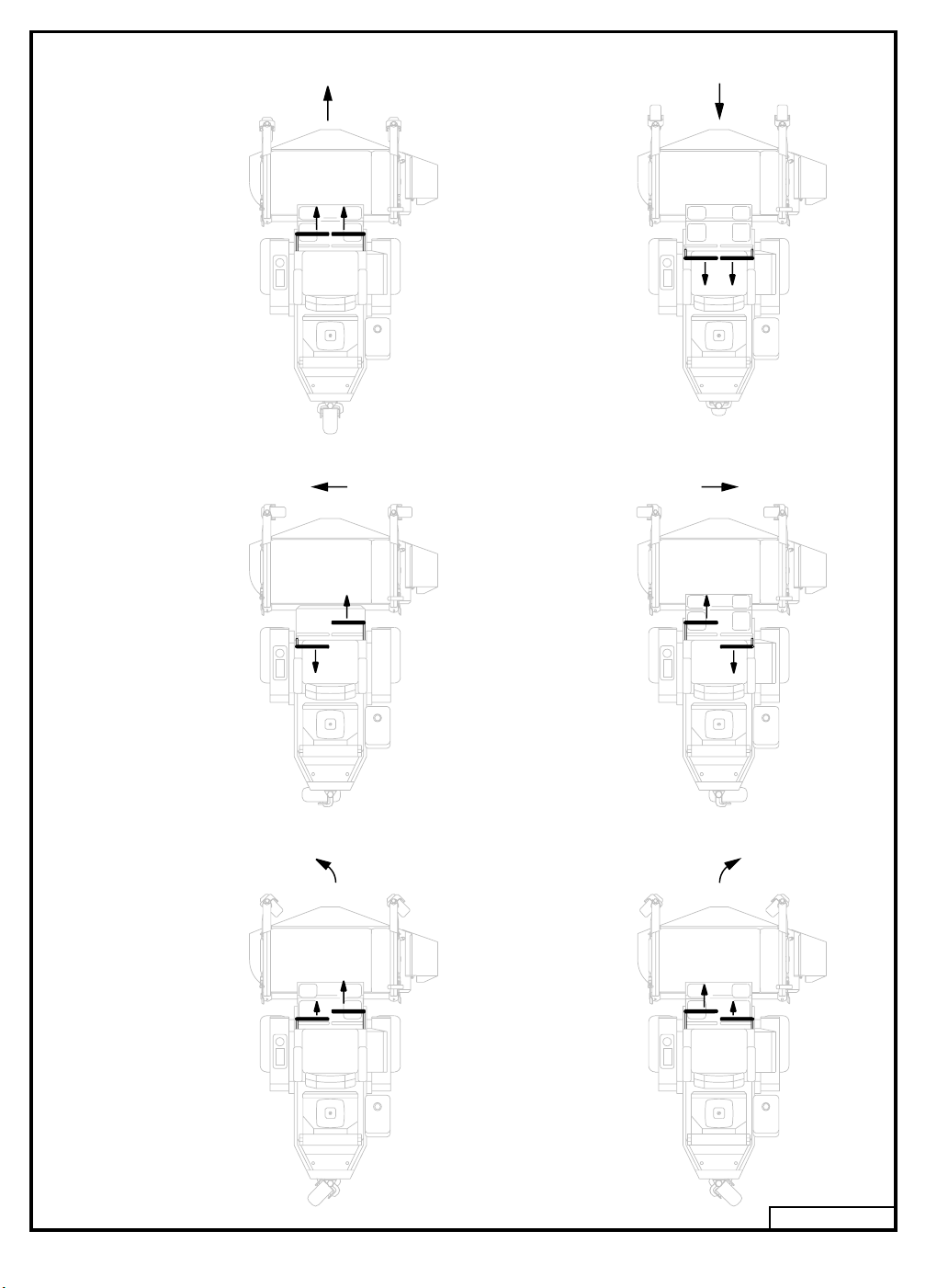
STEERING LEVER OPERATION
FORWARD
SHARP
LEFT
REVERSE
SHARP
RIGHT
GENTLE
LEFT
GENTLE
RIGHT
93052A
Fig. 4
18

LUBRICATION AND MAINTENANCE
CAUTION
Always wear safety glasses and ear
protection when performing any
maintenance function that could
cause injury to eyes or ears.
Read all safety information on pages 6 through 10.
CAPACITIES
Fuel Tank 723T ................... 4.3 U.S. gal. (16.3 l)
Fuel Tank 727T6................ 8.0 U.S. gal. (30.2 l)
Drive System .......................... 2.7 U.S. qt. (2.6 l)
Drive System Fluid Change
approx ...................... 2.2 U.S. qt. (2.08 l)
Optional Hydraulic Lift Capacity and
Fluid Change ............... 0.9 U.S. qt (.85 l)
WARNING
Lower attachment to ground, shut off
tractor engine, remove key and wires
to spark plugs before performing any
maintenance.
LUBRICATION
Do not let excess grease collect on or around parts,
particularly when operating in sandy areas.
The chart gives the frequency of lubrication in
operating hours based on normal operating conditions. Severe or unusual conditions may require
more frequent lubrication.
Use an SAE multipurpose type grease for all locations shown. Be sure to clean fitting thoroughly
before using grease gun.
For Drive System, use Hydro-Max Fluid, part no.
345050 for 1 quart (.94 l) container or part no.
345055 for 1 gallon (3.76 l) container.
TIRE AIR PRESSURE
Drive Tires
Standard 22 x 11 x 10 ............... 8 psi (55 kPa)
Optional 22 x 10 x 10 ................ 8 psi (55 kPa)
(refer to decal on wheel for correct tire air pressure)
Rear Tires ............... 12 to 15 psi (83 to 103 kPa)
DRIVE SYSTEM
Fluid Change ...................................... 500 hours
Filter Change ...................................... 500 hours
CRANKCASE OIL AND AIR FILTER
Refer to the “Engine Manual” for the time table
for changing or service.
COOLING SYSTEM
Inspect the engine cooling fins periodically for
buildup of grass and debris. Buildup on the cooling fins will cause the engine to overheat.
Removal of engine cowling may be required to
clean the fins, especially if cleaned infrequently.
Lubricate Every Lubricate Every
8 Hours of Usage 80 Hours of Usage
Rear Wheel Bearings Clutch Power Shaft
(one fitting) (two fittings)
Universal Half Shaft
(one fitting)
Rev. 08-08
CAUTION
Do not use high pressure water or
steam to clean the engine or drive
compartment. Water and cleaning
detergent may damage electrical
components and terminals, possibly
leading to component and safety
circuit failure.
Use a vacuum cleaner or air blower to remove
foreign material from the engine and drive compartment.
19

BATTERY MAINTENANCE
Follow the procedure below for battery maintenance.
• Clean battery.
• Inspect cables for loose connection.
• Clean terminals.
• Inspect battery tray and hold-down.
• Inspect battery case for cracks or leaks.
WARNING
Batteries contain sulfuric acid. Avoid
contact with skin, eyes, and clothing.
Batteries produce a highly explosive
hydrogen gas while being charged.
Always keep cigarettes, sparks, open
flame, and other sources of ignition
away from battery. Always shield
eyes and face from battery. In the
event of accident, flush with water and
call a physician immediately. Keep
batteries and acid out of the reach of
children.
CHECKING DRIVE SYSTEM FLUID
LEVEL
Check fluid level with the engine turned off. The
expansion tank is located on the right side under the
seat. To check the fluid level, place unit on level
surface and look through the side of the expansion
tank. The fluid level should be equal to the full mark
on the reservoir decal (Refer to Fig. 5). If fluid is
required, make certain that expansion tank plug and
the area around it is clean and free of any foreign
matter before adding fluid. Use Hydro-Max Fluid
(Grasshopper part number 345050 for 1 quart [.94
l] container).
CHANGING DRIVE SYSTEM FLUID
AND FILTER
(Refer to illustration page 31)
Change fluid and filter every 500 hours. To drain
fluid, remove drain plug from the bottom of tandem
hydro pump. Allow fluid to drain completely. Reinstall plug and tighten.
To replace filter (item 3), which is located in the bottom of tandem hydro pump, make certain that the
area around filter is clean and free of any foreign
matter. Remove the filter and replace with a new filter (Grasshopper part number 130505).
To refill the system with fluid, make certain that the
area around the expansion tank adapter (item 70) is
clean and free of any foreign matter. Disconnect the
hose (item 64) from the adapter and remove
adapter from tandem hydro pump. Refill the pump
with Hydro-Max Fluid (Grasshopper part number
345050 for 1 quart [.94 l] container). Reinstall
adapter in pump and reconnect hose to adapter.
Refill expansion tank with Hydro-Max Fluid to the
proper level (Refer to Fig. 5). Run engine and
check that fluid level in expansion tank is at the
proper level.
Note: No air bleeding is necessary since the
system is self-bleeding.
Fig. 5
20

ADJUSTMENTS AND TROUBLESHOOTING
CAUTION
Never make adjustments with the
engine running.
LOSS OF POWER IN THE DRIVE
SYSTEM
a straight line, adjust the steering lever
stop on the side that is the fastest i.e.: if machine goes to the left, adjust the right
steering stop to slow down the right transmission until travel is straight ahead.
PARKING BRAKE ADJUSTMENT
Check the fluid level and be sure the proper amount
of fluid is in the expansion tank. The cooling
fins and fan blades should be clean and free of
foreign matter.
NO POSITIVE NEUTRAL POSITION
If drive wheels travel forward or backward when
the steering lever is in swing-out position (neutral), adjustment is required.
NEUTRAL ADJUSTMENT
(Refer to illustration page 31)
1. Block up under tractor frame so both drive
wheels are off the ground.
2. Make sure parking brake is released.
3. Remove linkage rod (item 28 or 29) from
transmission control arm (item 17).
4. Place steering levers in the neutral swing-out
position and start engine.
5. If either of the drive wheels turn, proceed
with the following adjustment.
6. Loosen locking nut (item 20) and rotate
pivot bolt (item 18) until neutral is achieved.
Tighten locking nut.
(Refer to Fig. 6 and illustration on page 33)
Adjust the right and left brake individually. Disconnect the right brake linkage rod (item 25). Adjust
the linkage pin (item 27) to the left brake until it
takes 14 lbs of pull at the top of the hand lever to
apply the parking brake. Adjustment of brake linkage rod (item 22) may also be required. Connect
the right brake linkage.
Disconnect the left brake linkage rod and adjust the
linkage pin attached to the right brake until it takes
14 lbs of pull at the top of the hand lever to apply the
parking brake. Connect the left brake linkage.
With both brakes connected it should take 28 lbs of
pull at the top of the hand lever to apply the parking
brake. Adjust the brake linkage rod (item 22) if
necessary.
40 50
102030
0
97069A
NOTE: Pivot bolt roller is mounted off center
and works as an eccentric when the bolt is
turned.
7. Repeat procedure for other side transmission.
8. Reinstall linkage rod in control arm. If ball
stud does not reinstall into control arm without moving the control arm, adjust length of
linkage rod until it slides into control arm to
assure neutral adjustment will be maintained
when linkage is connected.
9. Test drive machine for straight line travel
with both levers full forward. If travel is not in
Fig. 6
CLUTCH REMOVAL /
REPLACEMENT
(Refer to page 27 or 29)
• Remove two carriage bolts (item 42). Lift out
weight cover and rear weights.
(Refer to page 36)
• Remove anti-rotation bracket (item 19).
• Using a 15/16 inch wrench, rotate the idler arm
(item 23) with idler pulley (item 30) away from
belts and remove drive belts (item 37).
21

• Unplug wires from clutch and remove center
bolt (item 18). Slide clutch off engine crankshaft.
• Reverse order to install new clutch.
• Torque clutch bolt to 50 ft lbs. Run clutch 15
minutes, then torque to 50 ft lbs again.
CLUTCH / BRAKE BURNISHING
IMPORTANT
A new clutch, or one that has not been
used for three months, will require
burnishing to dress drive surfaces.
The clutch could fail if you do not
accomplish the following procedure.
Place tractor in neutral and start engine. Turn
clutch switch on 30 seconds and off 30 seconds,
five times at half-throttle and repeat five times at
full throttle. The time interval allows the clutch
surface to cool.
ing. Make sure the parking brake is released.
The steering levers cannot be engaged with
the parking brake on. With the key switch
“ON” and the seat switch engaged, check for
ground at the two yellow wires on the seat
switch. If there is ground at one wire but not
the other, either the seat switch is defective or
it is not being activated properly.
• If there is ground at both yellow wires on the
seat switch, check for ground at the yellow
wire on the parking brake switch. If there is
no ground, the wire between the seat switch
and the parking brake switch is broken. If
there is ground at the yellow wire, check for
ground at the white wire. If there is no
ground at the white wire, the parking brake
switch is defective and must be replaced.
NOTE: These tests must be performed with an
accurate voltmeter. Do not use a test light; the
amperage in this circuit is too low to light a test
light properly. This circuit is the ground side of
relay A.
ENGINE TROUBLESHOOTING
Should you experience trouble in starting the engine,
use the following guide to locate possible causes.
Engine will not crank:
• Battery is discharged.
• Blown starter fuse.
• PTO switch is “ON”.
• Steering levers are not out in neutral.
• Steering lever switches are out of adjustment
(listen for the switch “click”).
• A loose wire or connection.
Engine cranks, but will not start:
• Fuel tank is empty.
• Restricted fuel line or fuel filter.
• Blown ignition fuse.
• A loose wire or connection.
If the above points do not locate the problem, contact your authorized Grasshopper dealer for repair.
Engine dies when steering levers are engaged:
• If engine starts and runs but dies when either
steering lever is engaged, check the follow-
WIRING CIRCUIT BOARD REMOVAL
Remove the circuit board from the console by compressing the keeper in each of the three circuit board
support spacers with needle nose pliers (refer to
Fig. 7). Slide the board past each keeper when it is
compressed.
Spacer - Circuit Board Support
Part no. 423690
Keeper
Needle Nose
Pliers
Circuit Board
Console Side
22
Fig. 7
95040

Foot Rest Block
Tap Screw
98035
33, 34 or 95
Series Decks
STEERING LEVER ADJUSTMENT
FOOT REST BLOCK INSTALLATION
To adjust steering levers, loosen adjustable nuts
that secure the levers to the lever mounts. This
allows the levers to be moved forwards or backwards (refer to Fig. 8). Set levers to a comfortable
position for the operator. Hold levers in an outward
position and tighten adjustable nuts. The levers
must line up when in neutral position and maintain
one inch of clearance between end of levers. If the
levers are allowed to lean toward center when the
adjustable nuts are tightened, free play in the mounting holes may allow the levers to hit each other.
1"
Adjustable
Nut
If installing a 33, 34 or 95 series deck on a 700 series tractor, install the foot rest blocks with the wide
end of block toward the front (refer to Fig. 9).
Fig. 9
If installing an SL96, SL98 series or 9772 deck on
a 700 series tractor, install the foot rest blocks with
the narrow end of block toward the front (refer to
Fig. 10).
Adjustable
Nut
99071
Fig. 8
SL96, SL98 Series
or 9772 Decks
Tap Screw
Foot Rest Block
98036
Fig. 10
23

TRACTION KIT INFORMATION
CAUTION
Always wear safety glasses and ear
protection when performing any
maintenance function that could
cause injury to eyes or ears.
Read all safety information on pages 6 through 10.
ADJUSTING TRACTION SPRING
TENSION
WARNING
Do not over extend springs. Over
extension will cause loss of weight to
rear of tractor. This could cause
operator to lose control of the
machine, particularly while going
down hill.
Set deck at a mid-height cutting position. Remove fender. Tighten adjusting bolt (refer to Fig.
11) until a distance of 1.25 inches is between
spring bracket and end of spring assembly. This
setting applies to all deck models. Tighten locking nut against end of spring and install wheel and
fender. Repeat on other side.
1.25"
Locking Nut
Adjusting Bolt
Spring Assembly
07084
Fig. 11
REMOVING MOWER DECK FROM
TRACTION KIT EQUIPPED
TRACTOR
Refer to mower deck manual and reverse attaching
procedure.
REAR WEIGHT REQUIREMENTS
WARNING
Additional weight may be required on
the rear of the Grasshopper tractor
when certain attachments are used.
See Weight Chart below.
Weight kits are available from your Grasshopper
dealer.
50 lb. (22.68 kg.) Weight ........ Part No. 503218
Weight Mount Kit................... Part No. 503220
COUNTERWEIGHT REQUIREMENTS - 700 SERIES
COUNTERWEIGHT NOT REQUIRED ON UNITS EQUIPPED WITH COLLECTION SYSTEM
Single Tail Wheel
w/o Grasscollector
Mower Deck
Model
9544 / SL9644 / 3344
9548 / SL9648 / 3348
9552 / SL9852* / 3452
9561 / SL9861* / 3461
9772
9772 w/ Elect. Height Adj.
9772 w/ Hyd. Deck Lift
AERA-vator 40"
AERA-vator 60"
Brooms: Bidirectional
Fixed Angle
Snowthrowers, 48" & 60"
* Deck Tilt Assist Kit: Requires an additional 50 lbs. of counterweight, unless unit is already equipped with
150 lbs. of counterweight.
This chart applies to both the standard single tail wheel and the optional dual tail wheel.
50 lbs. (22.68 kg.)
100 lbs. (45.36 kg.)
100 lbs. (45.36 kg.)
100 lbs. (45.36 kg.)
0
0
0
Not recommended
Not recommended
Includes Max Trax
of 150# counterweight with 72" deck.
50 lbs. (22.68 kg.)
50 lbs. (22.68 kg.)
w/ 4 Post Rated ROPS
or Enclosure
50 lbs. (22.68 kg.)
50 lbs. (22.68 kg.)
50 lbs. (22.68 kg.)
100 lbs. (45.36 kg.)
and 50# counterweight. Requires an additional 100# for a total
150 lbs. (68.04 kg.)
150 lbs. (68.04 kg.)
150 lbs. (68.04 kg.)
150 lbs. (68.04 kg.)
150 lbs. (68.04 kg.)
Other Than Single Tail Wheel
w/o Grasscollector
w/ 4 Post Rated ROPS
0
0
0
50 lbs. (22.68 kg.)
100 lbs. (45.36 kg.)
100 lbs. (45.36 kg.)
50 lbs. (22.68 kg.)
100 lbs. (45.36 kg.)
100 lbs. (45.36 kg.)
50 lbs. (22.68 kg.)
100 lbs. (45.36 kg.)
50 lbs. (22.68 kg.)
50 lbs. (22.68 kg.)
50 lbs. (22.68 kg.)
50 lbs. (22.68 kg.)
150 lbs. (68.04 kg.)
150 lbs. (68.04 kg.)
150 lbs. (68.04 kg.)
150 lbs. (68.04 kg.)
150 lbs. (68.04 kg.)
150 lbs. (68.04 kg.)
150 lbs. (68.04 kg.)
or Enclosure
24

PARTS LISTS AND ILLUSTRATIONS
When ordering parts, use the description and
part number as stated in this manual. Also
include the serial number of the tractor or
attachment on which the parts are to be used.
25

TRACTOR ASSEMBLY - 723T
ItemItem
Item
ItemItem
No.No.
No.
No.No.
10 603821 Throttle Assembly
11 422150 Handle Grip
12 902280 Spacer
13 422040 Tool Box
14 693210 Fender Rt.
15 693211 Fender Lt.
16 822635 Trim – Fender Edge
17 722062 Cover Panel - Right Fender
18 483942 Wheel & Tire 22 x 11 x 10
19 483943 Wheel & Tire 22 x 11 x 10
20 100156 Engine – 23 HP Kohler
21 100802 Oil Filter
22 100936 Air Filter – Outer Element
23 722975 Shield – Coupler
24 101217 Muffler
25 101001 Fuel Filter
26 605125 Bracket – Shield Mount
27 729270 Bracket – Lower Muffler
28 722309 Inner Panel – Shield
29 722391 Muffler Shield
30 693100 Console
31 721152 Console Fill Panel
32 142233 Mechanical Choke Cable
33 604835 Fuel Tank Assembly
OrderOrder
Order
OrderOrder
No.No.
No.
No.No.
1 644873 Lower Frame
2 644874 Upper Frame
3 253192 Whiz Bolt .312-18 x .75
4 253035 Whiz Nut .312-18
5 780900 Tension Rod
6 253200 Whiz Bolt .375-16 x .75
7 182253 Work Lamp
8 182251 Bezel – Snap Mount
9 253203 Whiz Bolt .375-16 x 1 Lg. Flange
323655 Cable Assembly
722009 Throttle Lever Stop
243335 Bolt .375-16 x 1.25
257040 Washer .375
482483 Tire 22 x 11 x 10 Bar Tread
483420 Wheel 10.00
483946 Wheel & Tire 22 x 10 x 10
482473 Tire 22 x 10 x 10 Turf Tread
900117 Engine Shim (as required)
100937 Air Filter – Inner Element
101041 Exhaust Gasket
DescriptionDescription
Description
DescriptionDescription
(includes cable assembly)
Bar Tread Rt.
Bar Tread Lt.
Turf Tread (optional)
(includes item 73)
ItemItem
Item
ItemItem
No.No.
No.
No.No.
34 141142 Gauge – Fuel
35 100210 Cap - Fuel
36 101875 Bushing – Fuel Tube
37 363925 Fuel Tube .25
38 821710 Fuel Line Hose
39 280260 Hose Clamp .25
40 323933 Counterweight – 34 #
41 729514 Weight Cover Plate
42 247325 Bolt .375 x 5.5 Carriage
43 643092 Deck Mount Rt.
44 643093 Deck Mount Lt.
45 247280 Bolt .375-16 x 2.75 Carriage Special
46 282575 Deck Mount Bushing
47 282576 Deck Mount Bushing – Floating (opt.)
48 253460 Nut .375-16 Nylon Insert
49 604346 Foot Rest w/Tread, Bearing, & Blocks
50 420905 Foot Platform Tread
51 422615 Nylon Bushing
52 780673 Threaded Rod – Foot Platform
53 253470 Nut .5-13 Nylon Insert
54 424052 Rubber Bumper
55 603301 Foot Platform Extension
56 420904 Foot Platform Extension Tread
57 247130 Carriage Bolt .312-18 x .75
58 643144 Fuel Tank Mounting Bracket
59 721123 Heat Shield
60 283312 Compression Spring
61 424100 Foot Rest Block
62 243026 Tap Screw .25 x 1
63 253043 Whiz Nut .375-16
64 644099 Battery Box
65 644162 Battery Cover
66 427273 Pad – Battery Tray
67 729001 Battery Clamp
68 257020 Washer .25
69 253175 Whiz Bolt .25-20 x .75
70 253025 Whiz Nut .25-20
71 253173 Whiz Bolt .25-20 x .5 Hex
72 253176 Whiz Bolt .25-20 x .5 Truss
73 254431 Speed Nut .25-20
74 424015 Rubber Bumper
75 422065 Square Plug 1"
76 364518 Nipple .375 x 2.5
77 143610 Valve – Oil Drain
78 363855 Fitting .375 NPT Female .375 Barb 90°
Item not pictured:
OrderOrder
Order
OrderOrder
No.No.
No.
No.No.
424275 Grommet – Fuel Gauge
253440 Nut .25-20 Nylon Insert
79 248565 Lug Bolt .5-20 x .875
605333 Decal Set - 723T Tractor
DescriptionDescription
Description
DescriptionDescription
26
02-07060
Rev. 01-08
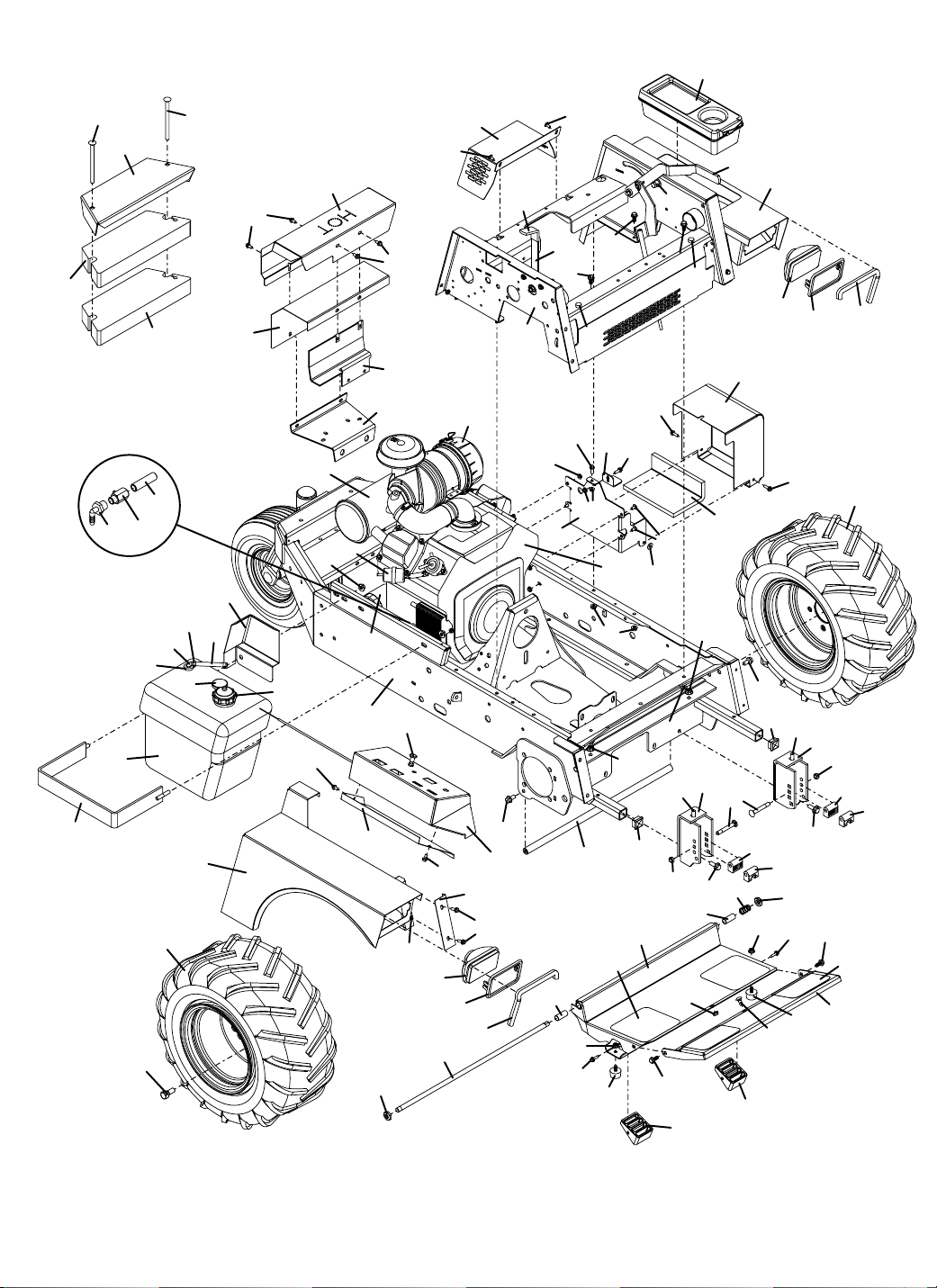
TRACTOR ASSEMBLY - 723T
13
40
58
42
41
78
33
79
77
36
40
76
37
18
07060
34
39
42
14
38
59
28
71
35
71
24
63
29
25
21
1
31
53
27
71
26
32
73
72
7
52
71
23
11
22
6
30
17
69
8
16
72
11
15
12
3
10
3
2
70
64
51
69
74
67
70
20
4
5
50
4
62
54
69
63
75
49
69
68
72
4
3
48
9
3
4
61
74
51
63
43
7
65
69
66
6
75
9
45
46
47
9
60
61
53
4
62
54
57
16
8
19
44
48
46
47
9
3
56
55
27

TRACTOR ASSEMBLY - 727T
6
ItemItem
Item
ItemItem
No.No.
No.
No.No.
10 603821 Throttle Assembly
11 422150 Handle Grip
12 902280 Spacer
13 422040 Tool Box
14 693210 Fender Rt.
15 693211 Fender Lt.
16 822635 Trim – Fender Edge
17 722062 Cover Panel - Right Fender
18 483942 Wheel & Tire 22 x 11 x 10
19 483943 Wheel & Tire 22 x 11 x 10
20 100190 Engine - 27 HP Kohler
21 100802 Oil Filter
22 100936 Air Filter – Outer Element
23 722975 Shield – Coupler
24 101217 Muffler
25 101001 Fuel Filter
26 605125 Bracket – Shield Mount
27 729270 Bracket – Lower Muffler
28 722309 Inner Panel – Shield
29 722391 Muffler Shield
30 693100 Console
31 721152 Console Fill Panel
32 142233 Mechanical Choke Cable
33 604844 Fuel Tank Assembly
34 141144 Gauge – Fuel
OrderOrder
Order
OrderOrder
No.No.
No.
No.No.
1 644873 Lower Frame
2 644874 Upper Frame
3 253192 Whiz Bolt .312-18 x .75
4 253035 Whiz Nut .312-18
5 780900 Tension Rod
6 253200 Whiz Bolt .375-16 x .75
7 182253 Work Lamp
8 182251 Bezel – Snap Mount
9 253203 Whiz Bolt .375-16 x 1 Lg. Flange
323655 Cable Assembly
722009 Throttle Lever Stop
243335 Bolt .375-16 x 1.25
257040 Washer .375
482483 Tire 22 x 11 x 10 Bar Tread
483420 Wheel 10.00
483946 Wheel & Tire 22 x 10 x 10
482473 Tire 22 x 10 x 10 Turf Tread
900117 Engine Shim (as required)
100937 Air Filter – Inner Element
101041 Exhaust Gasket
424275 Grommet – Fuel Gauge
DescriptionDescription
Description
DescriptionDescription
(includes cable assembly)
Bar Tread Rt.
Bar Tread Lt.
Turf Tread (optional)
(includes item 73)
ItemItem
Item
ItemItem
No.No.
No.
No.No.
35 100210 Cap - Fuel
36 101875 Bushing – Fuel Tube
37 363928 Fuel Tube .25
38 821710 Fuel Line Hose
39 280260 Hose Clamp .25
40 323933 Counterweight – 34 #
41 729514 Weight Cover Plate
42 247325 Bolt .375 x 5.5 Carriage
43 643092 Deck Mount Rt.
44 643093 Deck Mount Lt.
45 247280 Bolt .375-16 x 2.75 Carriage Special
46 282575 Deck Mount Bushing
47 282576 Deck Mount Bushing – Floating (opt.)
48 253460 Nut .375-16 Nylon Insert
49 604346 Foot Rest w/Tread, Bearing, & Blocks
50 420905 Foot Platform Tread
51 422615 Nylon Bushing
52 780673 Threaded Rod – Foot Platform
53 253470 Nut .5-13 Nylon Insert
54 424052 Rubber Bumper
55 603301 Foot Platform Extension
56 420904 Foot Platform Extension Tread
57 247130 Carriage Bolt .312-18 x .75
58 644826 Tank Mount - 8 Gallon
59 721181 Heat Shield - 8 Gallon
60 283312 Compression Spring
61 424100 Foot Rest Block
62 243026 Tap Screw .25 x 1
63 253043 Whiz Nut .375-16
64 644099 Battery Box
65 644162 Battery Cover
66 427273 Pad – Battery Tray
67 729001 Battery Clamp
68 257020 Washer .25
69 253175 Whiz Bolt .25-20 x .75
70 253025 Whiz Nut .25-20
71 253173 Whiz Bolt .25-20 x .5 Hex
72 253176 Whiz Bolt .25-20 x .5 Truss
73 254431 Speed Nut .25-20
74 424015 Rubber Bumper
75 422065 Square Plug 1"
76 364518 Nipple .375 x 2.5
77 143610 Valve – Oil Drain
78 363855 Fitting .375 NPT Female .375 Barb 90°
Item not pictured:
OrderOrder
Order
OrderOrder
No.No.
No.
No.No.
253440 Nut .25-20 Nylon Insert
79 248565 Lug Bolt .5-20 x .875
80 723339 Tank Shield - 8 Gallon
605335 Decal Set - 727T6 Tractor
DescriptionDescription
Description
DescriptionDescription
28
08004
Rev. 01-08

TRACTOR ASSEMBLY - 727T
6
13
6
58
40
42
78
33
41
80
36
79
77
40
37
18
08004
76
39
14
42
34
59
38
6
28
71
35
71
24
63
25
29
25
23
72
11
71
26
27
21
1
32
31
73
53
7
52
71
22
6
30
17
69
8
16
72
11
15
12
3
10
3
2
70
64
51
69
74
67
70
20
4
5
50
4
62
54
69
63
75
49
69
68
72
4
48
3
9
3
61
74
7
65
69
66
63
6
75
9
43
45
46
47
9
60
51
4
61
53
4
62
54
57
16
8
19
44
48
46
47
9
3
56
55
29

DRIVE ASSEMBLY
ItemItem
Item
ItemItem
No.No.
No.
No.No.
10 424385 Hose Assembly .5 x 23
11 424386 Hose Assembly .5 x 25
12 424070 Vibration Isolator – Flange
13 603611 Wheel Motor w/Hub (723T)
14 360063 Adapter Fitting 8MJ-10MB
15 243622 Sq Head Bolt .5-13 x 4
16 902299 Spacer – Wheel Motor
17 644862 Neutral Return Arm
18 603729 Roller Assembly – Eccentric
19 257410 External Star Washer
20 254450 Nut .375-16
21 257019 Washer .25 Hard
22 270832 Flange Bolt M6 x 1 x 40
23 253025 Whiz Nut .25-20
24 783730 Spacer – Neutral Return
25 253186 Whiz Bolt .312-24 x .75
26 265615 Ball Joint .312-24 RH Thread
27 265616 Ball Joint .312-24 LH Thread
28 780154 Rod – Steering Linkage 7.625
29 780156 Rod – Steering Linkage 13.0
30 254441 Nut .312-24 RH Thread
31 254444 Nut .312-24 LH Thread
32 253038 Whiz Nut .312-24
33 422039 Spacer – Return Plastic
34 775123 Spacer – Pump Mount
35 283823 Extension Spring
36 243030 Bolt .25-20 x 1.25
37 729542 Mount - Return
38 729639 Return Arm - Front
39 729398 Return Arm - Rear
40 424073 Vibration Isolator .375-16
41 725522 Front Mount – Tandem 700T
42 253192 Whiz Bolt .312-18 x .75
OrderOrder
Order
OrderOrder
No.No.
No.
No.No.
1 644875 Mount – Drive Train
2 391467 Hydro Pump - Tandem (723T)
391470 Hydro Pump - Tandem (727T6)
3 130505 Filter
4 130431 Fan (723T)
130434 Fan (727T6)
5 130432 Retainer - Fan
6 253461 Nut – Nylon Insert
7 360061 Adapter Fitting 8MB-8MJ 90°
8 360064 Adapter Fitting 8MB-10MJ
9 424384 Hose Assembly .5 x 22
603614 Wheel Motor w/ Hub (727T6)
DescriptionDescription
Description
DescriptionDescription
(includes items 19 & 20)
ItemItem
Item
ItemItem
No.No.
No.
No.No.
43 243215 Bolt .312-18 x 1.5
44 257030 Washer .312
45 243570 Bolt .5-13 x 1.5
46 257060 Washer .5
47 253066 Whiz Nut .5-13
48 774175 Washer – DD
49 388577 Coupler Hub – DD Bore
50 424150 Stabilizer - Coupling
51 253043 Whiz Nut .375-16
52 243206 Bolt .312-24 x 1
53 774176 Washer – 1 x 3
54 388560 Coupler Sleeve
55 281580 Sq. Key .25 x .690
56 388578 Coupler Hub 1"
57 774020 Washer - .406 x 1.25
58 243330 Bolt .375-16 x 1
59 253035 Whiz Nut .312-18
60 644094 Bracket – Expansion Tank
61 422033 Expansion Tank
62 365516 Plastic Plug - .375
63 423154 Tie .25 x 15
64 821709 Hydraulic Hose
65 280261 Clamp – Spring .312
66 821723 Vent Hose – Clear
67 722976 Shroud – Fan
68 722975 Shield – Coupler
69 130430 Fan Hub (723T)
70 130510 Expansion Tank Adapter
71 243350 Bolt .375-16 x 2.25
72 257412 Lock Washer .375
73 243045 Bolt .25-20 x 2.25
74 257392 Lock Washer .25
75 822304 Pivot Bearing – Neutral Return
76 257044 Washer – Fender
77 243335 Bolt .375-16 x 1.25
78 253890 Lock Nut .375-16
79 274114 Whiz Nut M6 x 1
80 253203 Whiz Bolt .375-16 x 1
81 243475 Bolt .437-14 x 3
82 253465 Nut .437-14 Nylon Insert
83 902548 Spacer 1 x 2
OrderOrder
Order
OrderOrder
No.No.
No.
No.No.
130433 Fan Hub (727T6)
84 424383 Hose Assembly .5 x 19.5
85 257025 Washer .257
86 253179 Whiz Bolt .25-20 x .75 Phil Truss
DescriptionDescription
Description
DescriptionDescription
30
01-07061A
Rev. 01-08

DRIVE ASSEMBLY
14
13
84
16
07061A
16
14
15
16
86
63
64
9
23
15
6
15
60
86
23
5
62
61
66
65
65
67
44
69
4
81
42
43
59
41
59
23
23
8
8
7
7
2
3
26
42
30
26
22
33
17
70
32
30
20
47
28
48
12
80
19
18
21
29
68
31
49
22
27
RIGHT
SIDE
52
57
20
24
25
77
76
59
82
27
75
50
18
31
51
39
79
42
77
59
17
85
74
75
23
76
73
42
39
38
58
37
72
74
57
75
15
40
73
35
36
76
15
16
51
38
23
71
78
35
56
76
14
36
75
34
55
1
10
78
46
11
14
16
45
46
40
LEFT
SIDE
13
53
83
54
45
59
51
Rev. 01-08
15
16
31

BRAKE ASSEMBLY
ItemItem
Item
ItemItem
No.No.
No.
No.No.
10 776274 Mount – Brake & Traction Kit
11 644588 Mount – Brake Caliper
12 481102 Caliper Brake Assembly – CW*
13 481103 Caliper Brake Assembly – CCW*
14 247130 Carriage Bolt .312-18 x .75
15 253035 Whiz Nut .312-18
16 644539 Brake Pivot Tube
17 732617 Mount – Brake Pivot
18 253200 Whiz Bolt .375-16 x .75
OrderOrder
Order
OrderOrder
No.No.
No.
No.No.
1 603611 Wheel Motor Assembly (723T)
603614 Wheel Motor Assembly (727T6)
2 604442 Hub & Rotor Assembly
775192 Brake Rotor – 8.0
259592 Socket Head Screw
3 254522 Jam Nut 1-20 w/Nylok
4 281860 Woodruff Key .312 x 1
5 248565 Lug Bolt .5-20 x .875
6 902299 Spacer – Wheel Motor
7 243622 Sq Head Bolt .5-13 x 4
8 257432 Lock Washer .5
9 254470 Nut .5-13
603150 Brake Pad Kit
603150 Brake Pad Kit
DescriptionDescription
Description
DescriptionDescription
(includes items 2 - 4)
ItemItem
Item
ItemItem
No.No.
No.
No.No.
19 253043 Whiz Nut .375-16
20 644035 Brake Lever
21 422150 Handle Grip
22 644036 Arm – Brake Linkage
23 265537 Clevis Yoke .312-24 x 2.5
24 254441 Nut .312-24
25 780158 Linkage Rod – Brake
26 265615 Ball Joint .312-24 RH Thread
27 880926 Linkage Pin – Brake
28 260606 Ring Cotter .047 x .312
29 243030 Bolt .25-20 x 1.25
30 243340 Bolt .375-16 x 1.5
31 257040 Washer .375
32 902280 Spacer
33 183894 Brake Switch
34 261284 Clevis Pin .312-18 x 1
35 257020 Washer .25
36 253038 Whiz Nut .312-24
37 881130 Spacer – Brake Lever
38 257063 Nylon Washer .50 ID
39 257030 Washer .312
40 253025 Whiz Nut .25-20
41 782851 Brake Strap
42 243195 Bolt .312-18 x .75
OrderOrder
Order
OrderOrder
No.No.
No.
No.No.
DescriptionDescription
Description
DescriptionDescription
*To determine CW or CCW, hold the brake assembly in hand with the ribs on brake facing
toward you and the lever in the disengaged position. The direction of rotation of lever, when
engaging brake, determines CW or CCW.
32
01-07062
Rev. 01-08

BRAKE ASSEMBLY
2
9
8
1
4
6
7
6
7
6
1
19
7
6
7
32
31
29
28
39
24
27
24
34
36
4
15
8
9
2
3
5
LEFT
8
9
8
9
14
10
15
42
21
40
38
20
35
28
6
37
38
41
SIDE
14
13
11
19
15
25
24
26
30
24
23
35
7
28
35
22
28
6
7
42
33
36
16
28
15
19
9
8
8
10
12
41
24
25
07062
9
15
17
18
3
5
RIGHT
SIDE
14
14
11
24
27
24
26
17
18
33

ROPS & SEAT ASSEMBLY
ItemItem
Item
ItemItem
No.No.
No.
No.No.
10 253191 Whiz Bolt .312-18 x .625
11 183871 Seat Switch - Twist
12 424095 Seat Isolator
13 644618 Seat Hinge Pin
14 253192 Whiz Bolt .312-18 x .75
15 253035 Whiz Nut .312-18
16 754240 Seat Handle – Dual Latch
17 754226 Reinforcement – Seat Handle
18 730230 Pivot Pin - Seat
19 284408 Torsion Spring
20 260606 Ring Cotter .047 x .312
OrderOrder
Order
OrderOrder
No.No.
No.
No.No.
1 321518 Seat Cushion
2 321519 Back Cushion
3 321523 Arm Rest
4 723386 Side Member – Rt.
5 723387 Side Member – Lt.
6 822630 Seat Edge Trim
7 644816 Seat Bottom
8 253193 Whiz Bolt .312-18 x 1
9 722388 Seat Panel
DescriptionDescription
Description
DescriptionDescription
ItemItem
Item
ItemItem
No.No.
No.
No.No.
21 253043 Whiz Nut .375-16
22 253176 Whiz Bolt .25-20 x .5
23 253025 Whiz Nut .25-20
24 324200 Seat Belt – Non Retract
25 243551 Bolt .5-13 x .75
26 257063 Nylon Washer .5
27 257062 Washer .5 SAE
28 253470 Nut .5-13 Nylon Insert
29 324103 ROPS Tube
30 901645 Spacer - ROPS
31 243840 Bolt .625-11 x 3.5
32 424176 Flap – Seat Panel
33 253970 Lock Nut .625-11
34 283516 Spring – Compression
35 422127 Cap – Seat Spring
36 253203 Whiz Bolt .375-16 x 1
37 774046 Bracket – Wiring Mount
38 722776 Clamp – Wiring Mount Bracket
39 253173 Whiz Bolt .25-20 x .5
OrderOrder
Order
OrderOrder
No.No.
No.
No.No.
DescriptionDescription
Description
DescriptionDescription
34
07063

29
ROPS & SEAT ASSEMBLY
9
2
1
28
27
3
31
31
30
30
31
31
28
8
11
16
23
35
22
17
8
12
35
34
33
25
36
20
6
34
24
19
22
7
8
8
8
27
4
3
26
10
22
8
23
14
8
36
18
32
39
26
22
8
8
13
38
10
5
25
14
13
15
23
37
10
6
24
12
35
21
33
07063

PTO SHAFT & CLUTCH ASSEMBLY
21
30
32
31
19
20
15
3
40
37
23
27
35
24
37
24
11
29
35
38
10
26
25
2
28
39
36
40
35
29
18
28
39
36
33
17
22
35
16
29
13
35
29
14
1
12
2
28
28
39
36
9
8
7
9
39
36
35
34
4
4
5
29
35
07064D
6
29
ItemItem
Item
ItemItem
No.No.
No.
No.No.
10 415650 Sheave
11 281588 Gib Key .25 x 1.5
12 388771 Electric Clutch
13 388875 Field Assembly w/Brake
14 388866 Armature & Rotor Assembly
15 902586 Spacer – 1.125 x .720
16 883803 Washer .312 x 11MM x 1.625
17 257422 Lock Washer .437
18 243456 Bolt .437-20 x 1.5
19 732407 Anti-Rotation Bracket
OrderOrder
Order
OrderOrder
No.No.
No.
No.No.
1 393759 Power Shaft
2 122044 Pillowblock Bearing
3 398914 Universal Half Sleeve – QD
4 401019 Splined Yoke - Quick Disconnect
5 121010 Cross & Bearing
6 401017 Yoke with Sleeve
7 263660 External Retainer
8 283525 Compression Spring
9 300014 Steel Ball
DescriptionDescription
Description
DescriptionDescription
(includes items 4 – 6)
(includes items 7-9)
ItemItem
Item
ItemItem
No.No.
No.
No.No.
20 422087 Clutch Bracket Cover
21 253192 Whiz Bolt .312-18 x .75
22 253035 Whiz Nut .312-18
23 824471 Idler Arm (includes items 24-26)
24 121756 Flange Bearing - Oilite
25 121651 Bearing Pedestal
26 257319 Washer - Spring
27 243365 Bolt .375-16 x 3
28 257040 Washer .375
29 253043 Whiz Nut .375-16
30 415610 Idler Pulley
31 243805 Bolt .625-11 x 1.75
32 257452 Lock Washer .625
33 644422 Sheave Guard
34 729287 Shield – PTO Shaft
35 253203 Whiz Bolt .375-16 x 1
36 243340 Bolt .375-16 x 1.5
37 381914 Belt
38 284428 Torsion Spring
39 257412 Lock Washer .375
40 774020 Washer .406
OrderOrder
Order
OrderOrder
No.No.
No.
No.No.
DescriptionDescription
Description
DescriptionDescription
36
05-07064D
Rev. 10-08

STEERING ASSEMBLY
5
6
1
5
20
21
16
15
20
14
21
22
3
1
3
3
19
2
23
10
9
18
17
9
8
24
10
4
18
3
15
16
9
11
12
11
13
22
2
23
10
7
4
18
13
9
24
12
11
13
10
18
17
07065A
ItemItem
Item
ItemItem
No.No.
No.
No.No.
1 604778 Steering Lever Assembly
2 643926 Steering Lever Mount
3 253195 Whiz Bolt .312-18 x 1.5 Hex
4 253035 Whiz Nut .312-18
5 422179 Handle Grip - Foam
6 422095 Vinyl Cap
7 604832 Pivot w/Stop & Bearings Rt.
8 604833 Pivot w/Stop & Bearings Lt.
9 422559 Sleeve Bearing w/Flange
10 243197 Stop Bolt .312-18 x .75
11 257063 Nylon Washer
07065A
Rev. 08-07
OrderOrder
Order
OrderOrder
No.No.
No.
No.No.
DescriptionDescription
Description
DescriptionDescription
(includes items 5 & 6)
(includes items 9, 10, 23 & 24)
(includes items 9, 10, 23 & 24)
ItemItem
Item
ItemItem
No.No.
No.
No.No.
12 283324 Compression Spring
13 253470 Nut .5-13 Nylon Insert
14 644601 Steering Pivot
15 253179 Whiz Bolt .25-20 x .75 Truss
16 253025 Whiz Nut .25-20
17 285032 Damper with Ball Socket
18 265680 Ball Stud
19 729404 Support – Steering Rod
20 254438 Nut .312-16 Adjustable Lever
21 257019 Washer .25 Hard
22 253450 Nut .312-18 Nylon Insert
23 422557 Sleeve Bearing
24 422556 Sleeve Bearing w/Flange
OrderOrder
Order
OrderOrder
No.No.
No.
No.No.
DescriptionDescription
Description
DescriptionDescription
37

WIRING DIAGRAM
ItemItem
Item
ItemItem
No.No.
No.
No.No.
OrderOrder
Order
OrderOrder
No.No.
No.
No.No.
DescriptionDescription
Description
DescriptionDescription
604967 Wiring Assembly
161128 Decal - Console
1 183806 Ignition Switch
254498 Nylon Nut - Ignition Switch
2 182326 Brake Indicator Light
3 182327 Oil Indicator Light
4 184179 Light Switch
5 183925 Clutch Switch
6 183860 Safety Switch - Rt. Steering
720160 Rt. Steering Switch Mount
7 183860 Safety Switch - Lt. Steering
720161 Lt. Steering Switch Mount
8 183871 Seat Safety Switch
9 182253 Worklamp Assembly
(includes item 10)
10 182005 Light Bulb
11 182251 Bezel
ItemItem
Item
ItemItem
No.No.
No.
No.No.
OrderOrder
Order
OrderOrder
No.No.
No.
No.No.
DescriptionDescription
Description
DescriptionDescription
12 181735 Fuse Holder
181470 Fuse 30 Amp. Auto
13 184271 Relay w/Mount
14 180315 Battery Cable 16"
425219 Battery Terminal Boot
15 180276 Ground Cable 16"
16 180125 Battery - 12V
17 181722 Fuse Block
184458 1 Wire Clip
184460 2 Wire Clip
184472 Double Clip
18 181470 Fuse 30 Amp. Auto
181462 Fuse 10 Amp. Auto
181460 Fuse 7.5 Amp. Auto
19 141551 Hour Meter
20 183894 Brake Switch
21 423690 Spacer - PC Board Support
1
2
BRAKE
P
OFF
IGNITION
3
OIL
RUN
START
FAST SLOW
PTO CLUTCH
THROTTLE
PULL
OUT TO
ENGAGE
5
LIGHTS
4
OFFON
CHOKE
19
HOURS
93046A
38
93046A / 03066D

WIRING DIAGRAM
YELLOW
RED W/WHITE
L
S
M
G
B
1
BLACK
7
LT
STRG
GREEN/YELLOW
BLUE
BLACK W/WHITE
BLACK
18
17
BLACK
11
21
11
BROWN
19
0
0
4
6
RT
STRG
BLACK
GREEN
BROWN
10
9
YELLOW
BROWN
5
BROWN
YELLOW W/BROWN
BROWN
13
10
9
BLACK
GREEN
BLACK
YELLOW
2
BRAKE
WHITE
21
BLACK
WHITE
WHITE
3
OIL
0
0
0
17
NO
NC
GREEN/YELLOW
20
LIGHT/AUX FUSE
GREEN
WHITE
YELLOW
YELLOW
7.5 AMP.
PTO FUSE
10 AMP.
START FUSE
7.5 AMP.
BLUE
RED W/WHITE
BLACK
YELLOW
REGULATOR FUSE
30 AMP.
17
21
YELLOW/BROWN
GREEN
30 AMP.
BLUE
13
BLUE
12
YELLOW
GREEN
SEAT
BLACK
GREEN
STARTER
YELLOW
8
RED
PURPLE
16
15
-
+
14
MAG.
OIL
SOLENOID
CLUTCH
GROUND
TO
ENGINE
REG.
ACCESSORY FUSES
03066D
GREEN
39

TAIL WHEEL OPTIONS
ItemItem
Item
ItemItem
No.No.
No.
No.No.
OrderOrder
Order
OrderOrder
No.No.
No.
No.No.
1 604366 Dual Fork With Nut
2 243922 Bolt .625-11 x 14
3 253970 Lock Nut .625-11
4 902425 Axle Spacer
5 604595 Pivot Housing - Rear Dual Fork
6 125855 Seal
7 122522 Tapered Bearing
8 123522 Bearing Cup
9 122523 Bearing Taper
10 123521 Bearing Cup
11 257320 Washer - Spring
12 254505 Jam Nut .75-16 Nylon Toplock
13 604596 Pivot Housing - Rear Fork
14 481434 Dust Cap
15 253243 Whiz Bolt .5-13 x 1
16 257061 Washer .5 x 2.25
17 833275 Oilite Bearing Reamed
18 243334 Bolt .375-16 x 1.25 Grade 8
19 824508 Axle Beam W/Bushing - Dual
20 830420 Spacer .375 x 1.156
DescriptionDescription
Description
DescriptionDescription
(includes items 18 & 32)
(includes items 18 & 32)
ItemItem
Item
ItemItem
No.No.
No.
No.No.
OrderOrder
Order
OrderOrder
No.No.
No.
No.No.
21 483865 Wheel & Tire Assembly
482355 Tire 13 x 6.50 x 6
483306 Wheel without Tire 6 x 4.5
22 902475 Bearing Spacer
23 120050 Wheel Bearing
24 247725 Bolt .625 x 7 Carriage
25 604365 Rear Fork With Nut
26 282615 Spacer .375 x 1.031
27 125855 Seal
28 604597 Rear Axle Pivot
29 824510 Axle Beam W/Bushing
30 902427 Axle Spacer
31 723008 Bolt Lock
32 257412 Lock Washer .375
33 481432 Dust Cap
11
11
11
7
8
32
DescriptionDescription
Description
DescriptionDescription
13 x 6.5 x 6 w/Bearing & Spacer
(includes items 18 & 32)
14
12
40
18
18
32
18
27
4
23
21
13
8
7
3
22
23
01089A / 01090A / 01091A / 01092A
26
25
24
4
01089A

TAIL WHEEL OPTIONS
14
12
29
28
32
18
11
16
17
17
11
11
7
8
8
7
27
01091A
18
11
33
12
11
11
7
8
32
15
26
25
3
4
23
18
18
32
10
5
20
21
21
9
6
3
24
22
23
4
30
4
14
1
01090A
2
31
21
12
15
16
17
19
17
18
32
28
10
11
11
11
7
8
20
21
21
9
6
3
4
30
1
01092A
2
31
41

TRACTION KIT
8
9
7
9
19
3
2
18
23
12
22
5
6
7
4
1
3
9
8
12
9
18
23
10
19
22
20
NOTE: Item 13 is not used with
33, 34, 96, 97 & 98 series decks;
use with all other decks and
attachments requiring traction
kit or hydraulic lift.
Not included with tractor assembly.
18
21
11
19
14
15
23
13
07066
17
16
16
17
21
14
20
15
19
18
11
04061
23
ItemItem
Item
ItemItem
No.No.
No.
No.No.
10 253192 Whiz Bolt .312-18 x .75
11 820320 Lift Chain (5 links)
OrderOrder
Order
OrderOrder
No.No.
No.
No.No.
1 603699 Rocker w/Bearing Rt.
121764 Oilite Bearing
2 603700 Rocker w/Bearing Lt.
121764 Oilite Bearing
3 644635 Pin
4 604803 Spring Assembly - Offset
5 243395 Bolt .375-16 x 4.5 Full Thread
6 254450 Nut .375-16
7 247254 Carriage Bolt .375 x 1.375 Special
8 253890 Lock Nut .375-16
9 732410 Lift Strap
DescriptionDescription
Description
DescriptionDescription
ItemItem
Item
ItemItem
No.No.
No.
No.No.
12 253035 Whiz Nut .312-18
13 604708 Rocker Arm Extension Kit (opt.)
14 260523 Hair Pin .094 x 2
15 257040 Washer .375
16 261362 Clevis Pin .375 x 1.75
17 262950 Push-on Retainer
18 261339 Clevis Pin .375 x .875 Sq. Shank
19 260648 Cotter Pin .125 x .5
20 644706 Extension - Rocker Arm
21 253203 Whiz Bolt .375-16 x 1
22 253043 Whiz Nut .375-16
23 820317 Lift Chain (3 Links)
OrderOrder
Order
OrderOrder
No.No.
No.
No.No.
DescriptionDescription
Description
DescriptionDescription
(includes 2 each of items 11 & 18-22)
42
04061 / 07066

COUNTERWEIGHT MOUNT KIT
5
2
5
4
3
4
6 *
3
ItemItem
Item
ItemItem
No.No.
No.
No.No.
OrderOrder
Order
OrderOrder
No.No.
No.
No.No.
DescriptionDescription
Description
DescriptionDescription
95043
4
ItemItem
Item
ItemItem
No.No.
No.
No.No.
1
OrderOrder
Order
OrderOrder
No.No.
No.
No.No.
5
DescriptionDescription
Description
DescriptionDescription
503220 Counterweight Mount Kit
1 643915 Weight Mount
2 729691 Weight Cover
3 240151 Hook Bolt .375-16 x 6
95043
4 253203 Whiz Bolt .375-16 x 1
5 253043 Whiz Nut .375-16 Lg Flange
*6 503218 Counterweight - 50#
* Not Included in Kit
43

LIMITED UNIVERSAL HARNESS
(OPTIONAL ON ALL NON-HYDRAULIC LIFT MODELS)
BLACK
6 WAY WEATHER-PACK
CONNECTOR
MALE TERMINALS
GROUND
TO
ENGINE
GREEN/YELLOW
RED/WHITE
40
1
THIS CONNECTOR
STAYS WITH TRACTOR
A
B
DF
CE
THIS CONNECTOR
COMES
WITH THE
ACCESSORY HARNESS
6 WAY
F
E
B
CD
A
WEATHER-PACK
CONNECTOR
FEMALE TERMINALS
BROWN
2
GREEN/YELLOW
RELAY MOUNTS IN LEFT
REAR CORNER OF FRAME
BROWN
TO PTO CLUTCH SWITCH
EXISTING CONNECTOR
FROM WIRING HARNESS
ItemItem
Item
ItemItem
No.No.
No.
No.No.
OrderOrder
Order
OrderOrder
No.No.
No.
No.No.
DescriptionDescription
Description
DescriptionDescription
605957 Limited Universal Harness
1 181475 Fuse Auto - 40 Amp.
2 184271 Relay
GREEN
BROWN
BROWN
GREEN
CLUTCH
EXISTING PTO CLUTCH
CONNECTOR
05066
05066
44

HYDRAULIC LIFT WIRING ASSEMBLY
6
2
RED
BLACK
YELLOW
1
YELLOW/BROWN
CAB
FUSE BLOCK
4
PURPLE
3
CBA
GREEN
GROUND TO ENGINE
ItemItem
Item
ItemItem
No.No.
No.
No.No.
OrderOrder
Order
OrderOrder
No.No.
No.
No.No.
DescriptionDescription
Description
DescriptionDescription
1 144950 Hydraulic Solenoid
2 183710 Tilt Switch
3 183940 Push Button Switch
4 184973 Weather Pack Connector
5 181460 Accessory Fuse - 7.5 amp Auto
6 722747 Mount - Tilt Switch
BLACK
5
BLACK
45

HYDRAULIC LIFT ASSEMBLY
ItemItem
Item
ItemItem
No.No.
No.
No.No.
10 100728 Dipstick
11 603330 Fitting with Strainer
12 363826 Fitting - Barb
13 821724 Hose – Vent
14 360062 Adapter Adj. Stem 90°
15 360080 Adapter Fitting
16 360053 Adapter
17 363846 Fitting Stem Swivel 90°
18 360082 Adapter Adj. Stem 90°
19 360048 Adapter O-Ring 90°
20 360005 Adapter Tee NPT/Flare
21 360045 Adapter M NPT/F O-Ring
22 780507 Flow Restrictor
23 424301 Hose Assembly .25 x 13 MB
24 821783 Hose – Hydraulic .375 x 13.5
25 821776 Hose – Hydraulic .375 x 11
26 821797 Hose – Hydraulic .5 x 10
OrderOrder
Order
OrderOrder
No.No.
No.
No.No.
1 290074 Pump – Hydraulic CCW w/Solenoid
144950 Solenoid Valve
2 281540 Square Key .125 x 1
3 775049 Spacer
4 725504 Mount – Hydraulic Pump
5 831436 Sheave
6 381886 Belt
7 902546 Spacer 1 x 1.25
8 831443 Sheave
9 644845 Oil Tank – Aux.
DescriptionDescription
Description
DescriptionDescription
ItemItem
Item
ItemItem
No.No.
No.
No.No.
27 280264 Hose Clamp – Spring .375 TOC
28 280266 Hose Clamp – Spring .5 TOC
29 290021 Cylinder – Hydraulic
30 360052 Adapter M O-Ring/M Flare
31 424310 Hose Assembly .25 x 32.5
32 424550 Hose Assembly .25 x 27
33 887119 Pin – Cylinder Mount
34 257062 Washer .5 SAE
35 253066 Whiz Nut .5-13
36 263500 Retainer – External .5 x .042
37 261339 Clevis Pin .375 x .875 Sq. Shank
38 260648 Cotter Pin .125 x .5
39 253193 Whiz Bolt .312-18 x 1
40 253035 Whiz Nut .312-18
41 643915 Mount – Weight
42 323951 Counterweight
43 729691 Weight Cover
44 240151 Hook Bolt .375-16 x 6
45 253043 Whiz Nut .375-16
46 253203 Whiz Bolt .375-16 x 1
47 604779 Steering Lever Assembly w/Switch
48 422095 Vinyl Cap
49 422179 Handle Grip
50 604799 Switch/Mount Assembly
OrderOrder
Order
OrderOrder
No.No.
No.
No.No.
290096 Cylinder Seal Kit
DescriptionDescription
Description
DescriptionDescription
(includes items 48-50)
46
07067A

HYDRAULIC LIFT ASSEMBLY
45
44
43
46
46
45
RIGHT
SIDE
36
41
6
45
47
50
42
49
46
7
39
5
39
4
35
34
33
39
29
45
30
44
46
17
8
32
16
40
3
2
37
40
38
19
16
17
LEFT
SIDE
1
18
27
27
25
23
22
27
27
24
17
28
35
34
15
26
21
33
14
20
40
28
39
40
36
9
10
48
29
38
30
37
31
12
13
11
07067A
47
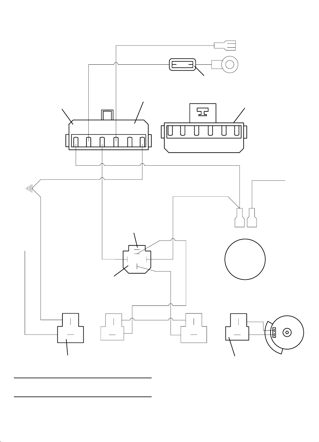
STANDARD UNIVERSAL HARNESS
(ALL HYDRAULIC LIFT MODELS)
BLACK
6 WAY WEATHER-PACK
CONNECTOR
MALE TERMINALS
GROUND
GREEN/YELLOW
TO
ENGINE
RED/WHITE
40
1
THIS CONNECTOR STAYS
WITH TRACTOR
THIS CONNECTOR COMES
WITH THE
ACCESSORY HARNESS
A
CE
B
FD
F
DE
B
C
A
6 WAY WEATHER-PACK
CONNECTOR
FEMALE TERMINALS
BROWN
PURPLE
EXISTING WIRE
BROWN
TO DECK LIFT
SWITCH
2
GREEN/YELLOW
RELAY MOUNTS IN LEFT
REAR CORNER OF FRAME
BROWN
TO PTO CLUTCH SWITCH
EXISTING CONNECTOR
FROM WIRING HARNESS
ItemItem
Item
ItemItem
No.No.
No.
No.No.
OrderOrder
Order
OrderOrder
No.No.
No.
No.No.
DescriptionDescription
Description
DescriptionDescription
605959 Universal Harness
1 181475 Fuse Auto - 40 Amp.
2 184271 Relay
GREEN
HYDRAULIC DECK
LIFT SOLENOID
BROWN
BROWN
GREEN
CLUTCH
EXISTING PTO CLUTCH
CONNECTOR
05065
05065
48


 Loading...