

The star in your cabinet
Grass
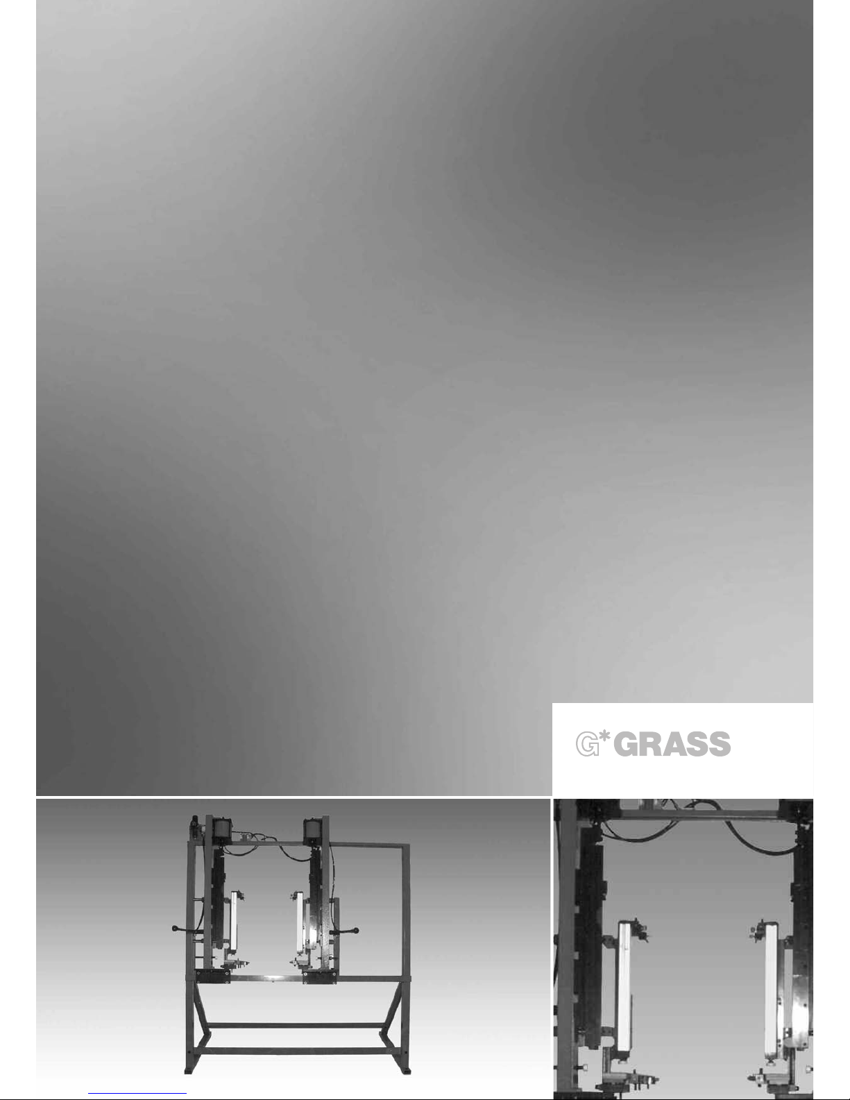
ZPM
OPERATING INSTRUCTIONS

TECHNICAL DATA
The star in your cabinet
2
Dimensions:
M
achine’s width for standard model 1600 mm
Machine’s total height @ 1800 mm
Machine’s depth @ 1000 mm
Other Specifications:
Insertion force of each side with 0.6 MPa (6 bar) @ 650 KP
Maximum total width for standard model 1000 mm
(Maximum floor width 936 mm)
Maximum front height for standard model 700 mm
Maximum back wall height for standard model 350 mm
Maximum lateral front overhang on the standard model 20 mm
Maximum lower front overhang on the standard model 100 mm
Zargen slides which can be used: 6035, 6036, 6136, 6236, 6436
Zargen lengths which can be used: 270, 350, 400, 440, 470, 510, 550
Weights:
Total weight of the basic equipment 185.00 kg
Weight of the change-over insert, length = 270 3.79 kg
Weight of the change-over insert, length = 350 3.97 kg
Weight of the change-over insert, length = 400 4.13 kg
Weight of the change-over insert, length = 440 4.31 kg
Weight of the change-over insert, length = 470 4.43 kg
Weight of the change-over insert, length = 510 4.61 kg
Weight of the change-over insert, length = 550 4.79 kg
Pneumatic Connections:
Dust-, water- and oil free air pressure at least 5.5 bar
Maximum allowable setting of pressure reducer 6.5 bar
Maximum pressure in supply line 10 bar
Pneumatic air used per stroke with 6 bar 1.2 l
Pneumatic air used per stroke, suction capacity for compressor 7.2 l

TABLE OF CONTENTS
The star in your cabinet
3
Page
1
. General 5-6
1-001 List of illustrations 5
1-002 Manufacturer information 6
1
-003 Copyright information 6
1-004 Terms of the guarantee 6
2. Safety Information 7-9
2-001 Safety information 7
2-002 Usage, according to regulations 7
2-003 Other risks, according to EN 292-2 8
2-004 Safety devices 8
2-005 Description of stickers 9
2-006 Danger- and safety measures 9
3. Description of Products 10-11
3-001 Usage 11
3-002 Identification of products 11
3-003 Basic equipment 11
3-004 Standard accessories 10-11
3-005 Special accessories 11
4. Description of Machine Components 12-17
4-001 Overview of numbered individual parts 12-13
4-002 Description of individual assembly parts 14-15
4-003 Description of operating elements 16
4-004 Functions of the ZPM - Producing drawers with the ZPM 16-17
5. Shipping and Installation of Machines, Service Personnel 18-19
5-001 Shipping and storage requirements, Center of gravity 18
5-002 Space and environment requirements 19
5-003 Assembly at the final installation site 19
5-004 Requirements of operating personnel 19
6. Start-Up 20-21
6-001 Pneumatic connection 20
6-002 Pneumatic diagram 20-21

TABLE OF CONTENTS
The star in your cabinet
4
7. Changing Over and Adjusting the ZPM 22-23
7
-001 Checking the wood parts 22-23
7-002 Mounting the index stops 24-25
7-003 Setting the drawer width 24-25
7-004 Changing to another drawer width 26-27
7
-005 Changing to another Zarge slide height 26-27
7-006 Changing to another Zarge slide length 26-27
7-007 Setting the back wall height stops 26-27
7-008 Setting the front height stops 28-29
7-009 Setting the front side stops 28-29
7-010 Setting the back wall thickness 30-31
7-011 Setting the bottom thickness 30-31
7-012 Setting the angles between the drawer front and drawer bottom 32-33
8. Trouble Shooting and Problem Solving 34-35
8-001 Gap between the drawer front and Zargen slide 34
8-002 Gap between the drawer bottom and bottom support with Zargen slide 34
8-003 Gap between the drawer bottom and drawer back wall 34
8-004 Gap between the Zargen slide and back wall inside the drawer 34
8-005 Gap between the Zargen slide and bottom inside the drawer 35
8-006 Correcting the angle between the drawer bottom and drawer front 35
8-007 Back wall dowel not inserted properly / Gap between the back wall and
Zargen slide 35
8-008 Drawer cannot be removed easily from the Zargen press ZPM 35
9. Maintenance and Care 36
9-001 Maintenance plan 36
9-002 Care information 36
10. Miscellaneous 37-51
10-001 Guarantee certificate 37-38
10-002 Disposal form 39-40
10-003 Resale form 41-42
10-004 Questionnaire 1 43-44
10-005 Questionnaire 2 45-46
10-006 List of Grass distributors 47

LIST OF ILLUSTRATIONS
The star in your cabinet
5
1-001 List of Illustrations
Illustration Description page
3-006 Miscellaneous standard accessories 10
4-001-01 General overview of the ZPM 12
4-002-01 Sectional view of the ZPM 14
4-002-02 Sectional view of the ZPM 14
4-004-01/.../06 Producing a drawer 16
5-001-01 Center of gravity of the Zargen slide press ZPM 18
6-002-01 Pneumatic diagram 21
7-001-01 Control dimensions for the drawer fronts for 6035 22
7-001-02 Control dimensions for the drawer fronts for
6036 / 6136 / 6236 / 6436 22
7-001-03 Control dimensions for the drawer bottoms for 6035 22
7-001-04 Control dimensions for the drawer bottoms for
6036 / 6136 / 6236 / 6436 22
7-001-05 Control dimensions for the drawer back walls for 6035 22
7-001-06 Control dimensions for the drawer back walls for
6036 / 6136 / 6236 / 6436 22
7-002-01 Mounting the index stops 24
7-003-01 Setting the drawer width 25
7-006-01 Changing to another Zargen slide length 27
7-007-01 Setting the back wall height stops 27
7-008-01 Setting the front height stops 29
7-009-01 Setting the front side stops 29
7-010-01 Setting the back wall thickness 31
7-011-01 Setting the bottom thickness 31
7-012-01 Setting the angles between the drawer front and the drawer bottom 33

1. GENERAL INFORMATION
The star in your cabinet
6
1-002 Manufacturer information
G
rass GmbH Tel. +43/(0)5578/ 701-0
Grass Platz 1 Fax. +43/(0)5578/ 701-59
6973 Höchst Internet: www.grass.at
Austria E-Mail: info@grass.at
1-003 Copyright information
The manufacturer has exclusive copyrights of these documents. Any means of copying is permitted only with
the permission of the manufacturer, unless the operating instructions are copied specifically for the purpose of
utilizing the machine.
1-004 Terms of the Guarantee
The delivered ZPM comes with a guarantee that is within the scope of the „General Terms of Guarantees in the
Association of the Machinery and Steel Construction Industry.“ Misuse of the product, repairs by
unauthorized or untrained personnel, use of unauthorized replacement parts or accessories without written approval from the manufacturer invalidate any guarantee claims.
We reserve the right to make technical modifications for whatever reason. When the machine is shipped from
the manufacturing plant, it meets the latest regulations and technical standards.
The manufacturer is under no obligation to modify machines free of charge because of changed
specifications.
To make a guarantee claim, please contact an authorized Grass representative or an authorized Grass
distributor and give them the machine model and number.
Lists of representatives and distributors can be found in Section 10-006.
Guarantee claims will only be honored if the guarantee certificate was filled out completely and sent to
the manufacturer. The guarantee form is in Section 10-001.
The guarantee and warranty include exclusively the replacement or repair of defective parts.
Not included in the guarantee are:
- shipping damages (These damage claims should be filed with the postal
service, the railway company or the shipping company.),
- natural wear and tear of parts,
- drill bits,
- damages resulting from negligence of safety regulations,
- damages resulting from inappropriate handling or misuse of the ZPM,
- damages to or from the work material,
- reimbursement of down time,
- loss of earnings or wages because of a defective ZPM,
- installation time, driving time or travel expenses.

2. SAFETY INFORMATION
The star in your cabinet
7
2-001 Safety Information
-
It is the responsibility of the owners of the machines to make sure that only properly trained personnel
operate the machine.
- The pneumatic connection lines are to be installed correctly and are to be protected from damaging effects.
(For example, in cable channels, conduits, or something similar).
-
The safety devices, which are included in the shipment, must always be utilized according to Point 2-004 and
must not be by-passed or rendered inoperable.
- During service or maintenance work, the air pressure supply lines must be separated from the machine
(by quick coupling, for example).
- Before operating the machine again, check all safety devices thoroughly to make certain that they are
functioning properly. Replace damaged parts only with authorized parts.
- Keep the workplace and surrounding area clean. Messy and disorganized work places increase the risk
of injury.
- The work area must be completely dry. Do not use the machine outside and, especially, do not leave
the machine out in the rain.
- Keep unauthorized people away from the machine.
- Only one person shall operate the machine at a time.
2-002 Recommended Usage
- The Grass Zargen press, model ZPM, is to be used expressly for the insertion of the Grass Zargen System
6000 on a wooden bottom, wooden back wall and a wooden front. Solid wood and other wood derived
materials can be used.
Other uses are not specified or allowed; thus, the manufacturer is not liable for resulting damages. The user
alone assumes all risks.
- The user must conform to the operating instructions when determining the appropriate usages.
- The machine shall only be operated, serviced and maintained by trained and authorized persons.
- The original set-up may not be modified without the express consent of Grass, Inc.

2. SAFETY INFORMATION
The star in your cabinet
8
2-003 Risks according to EN 292-2
T
he Zargen press, model ZPM, is manufactured in accordance with the present state of technology and current
safety and technical directives. Still, there remain risks to the life and health of the operators or of third parties,
and damages to the machine and other material assets.
Other risks consists of:
-
operation of the machine by unqualified personnel,
- operation of the machine without the required and recommended safety devices,
- additional people being in the work area of the operating machine,
- handling a machine that has not been properly secured and turned off,
- not maintaining the procedural instructions which are described in Section 7-0, which concerns
operating the ZPM,
- the malfunction of control elements.
These risks can be reduced if the operators and owners comply with Section 2-0 and Section 7-0.
2-004 Safety Devices
Safety devices and danger notices, etc. serve to ensure safety and may NOT, in any case, be removed or be
made inoperable.
- The pneumatic-filter-reducing regulator prevents the machine from overloading.
- The 2-handed pneumatic valve prevents an unintentional stroke disengagement or release.
Pneumatic diagram, Section 4-006.
2. SAFETY INFORMATION
The star in your cabinet
9
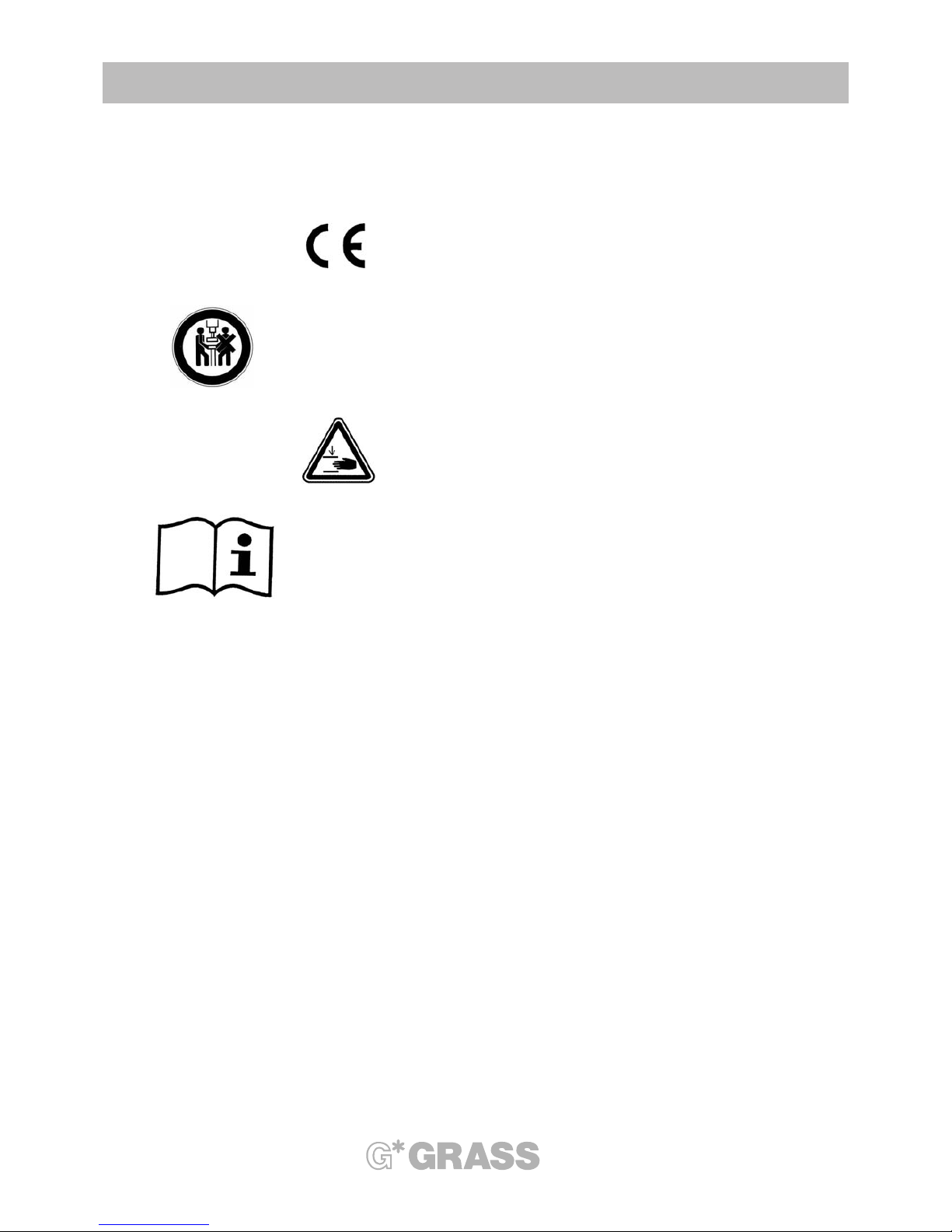
2-005 Description of Stickers
This sticker indicates conformity with the
E
uropean Community agreement.
Prohibitive sign: Only one person shall operate the
machine at a time.
Warning sign: Danger of crushing. Keep hands or
other objects clear.
Operating instructions: Read information thoroughly.
2-006 Dangers and Safety Measures
Dangers Safety Measures
Forward feed mechanism no automatic forwarding feed movement
Risk of impact This is not applicable because the stroke motion
is slow.
Tool unit The forward feed for the stroke motion is activated
by non self-locking buttons with collar. This meets
the safety guidelines EN 294 with regard to the risks.
Control system non self-locking button with collar
unexpected stroke disengagement 2-handed safety control
Control system defect Use only authorized replacement parts
The star in your cabinet
10
3. DESCRIPTION OF PRODUCTS
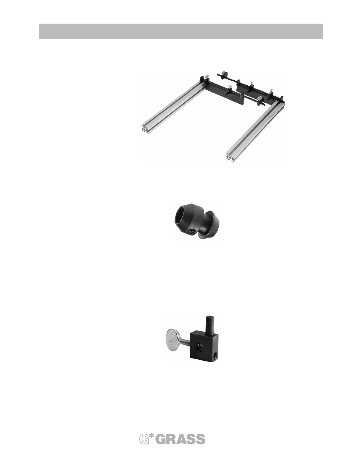
Change-over inserts
Index stop
Front height stop

3. DESCRIPTION OF PRODUCTS
The star in your cabinet
11
3-001 Usage
T
he Zargen press ZPM is designed exclusively for pressing and inserting the Grass Zargen slide with a wood
back wall, a wood bottom and a wood front. Solid wood, other materials derived from wood, such as particle
board, MDF-boards, glued and bonded woods, etc. can be used. The manufacturer guarantees smooth and
problem free operation for these usages with the machine. Violations or misuse may result in injuries to
t
he machine operators or to damages to the machine or work pieces.
3-002 Identification of Products
All machines are provided with an identification plate on which the manufactured year, the machine number and
model, as well as the required pneumatic pressure, are listed. There is also a sticker label on the machine frame
that has the machine identification.
3-003 Basic Equipment
The Zargen press ZPM , completely installed, consists of:
- a stabile durable machine frame,
- a rigid insertion unit, left,
- over the index stops, there is a movable insertion unit, right,
- complete pneumatic control system with 2-handed safety control system,
- complete operating instructions,
- tool kit, consisting of 13 mm and 17 mm open-ended fork wrench, an adjustment gauge for front stops and
one of each of these size Allen key wrenches: 2.5 mm, 3 mm, 4 mm, 5 mm, 6 mm.
3-004 Standard Accessories
Description Article Number
Front height stop ( back wall height stop) 88918
Index stop for drawer width 90651
Change-over insert for Zargen slide length 270 88910
Change-over insert for Zargen slide length 350 88911
Change-over insert for Zargen slide length 400 88912
Change-over insert for Zargen slide length 440 88913
Change-over insert for Zargen slide length 470 88914
Change-over insert for Zargen slide length 510 88915
Change-over insert for Zargen slide length 550 88916
3-005 Special Accessories
Various special accessories are available upon request.
For example: a fence for the Zargen press for the backside to prevent reaching into the ZPM.
Special index stops
Special front side stops
4. DESCRIPTION OF MACHINE COMPONENTS
The star in your cabinet
12
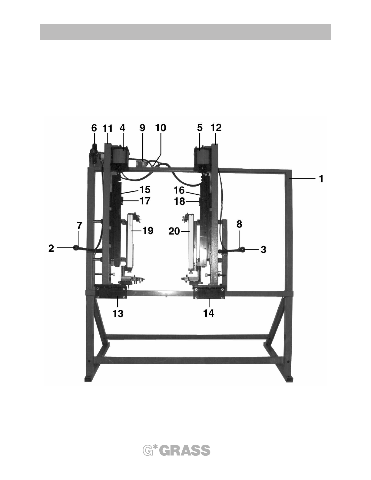
Illustration 4-001-01

4. DESCRIPTION OF MACHINE COMPONENTS
The star in your cabinet
13
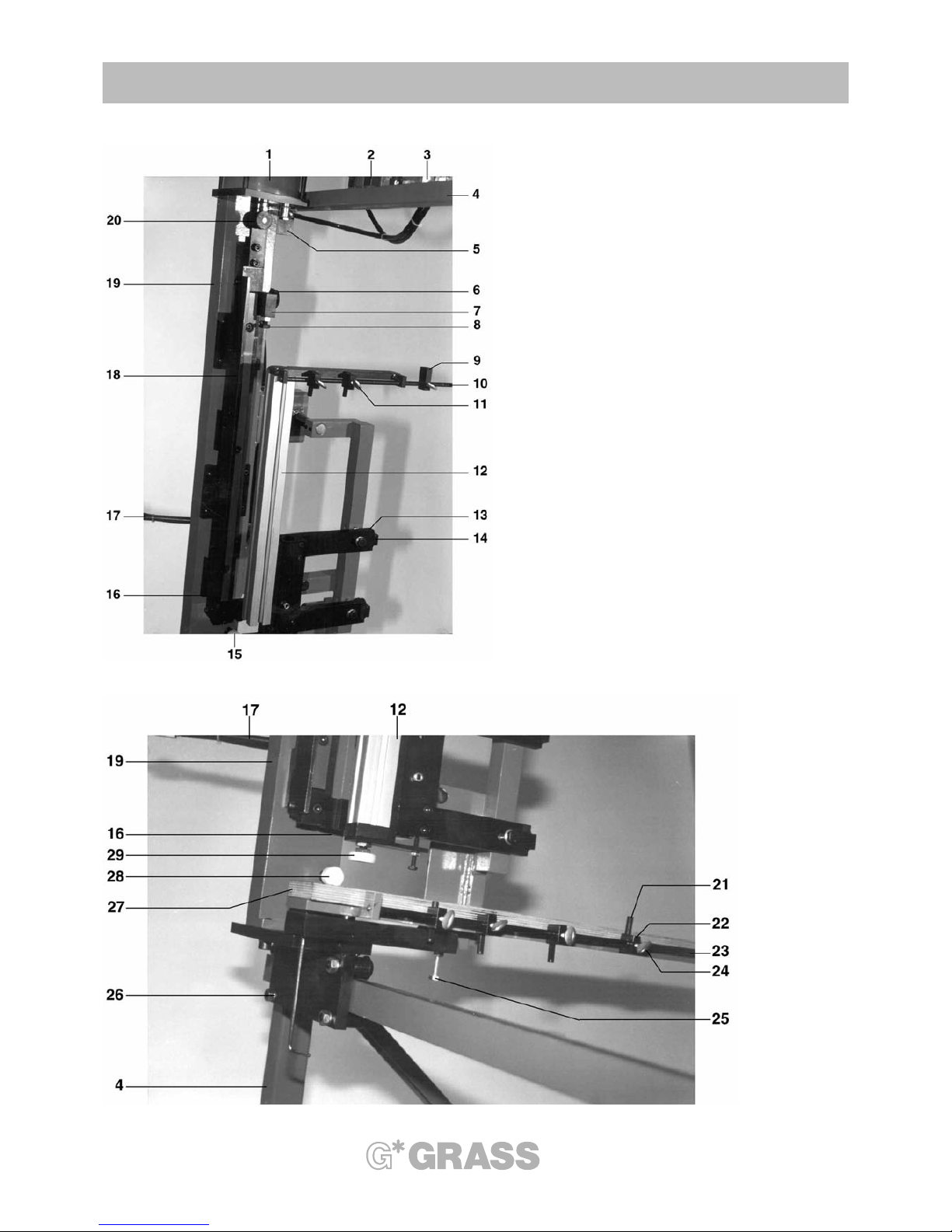
4-001 Overview of numbered individual parts Illustration 4-001-01
1
. Machine frame
2. Left hand lever
3
. Right hand lever
4. Left insertion cylinder
5. Right insertion cylinder
6. Compressed air regulator
7. Left starting valve
8. Right starting valve
9. 2-handed safety control system
10. Pneumatic operating valve
11. Left unit carrier
12. Right unit carrier
13. Left carriage
14. Right carriage
15. Left compression slide
16. Right compression slide
17. Back wall dowel - compression die fence, left
18. Back wall dowel - compression die fence, right
19. Left change-over insert
20. Right change-over insert
4. DESCRIPTION OF MACHINE COMPONENTS
The star in your cabinet
14
Illustration 4-002-01
Illustration 4-002-02

4. DESCRIPTION OF MACHINE COMPONENTS
The star in your cabinet
15
4-002 Description of individual assembly parts Illustration 4-002-01 and 4-002-02
1
. Insertion cylinder, diameter 120 stroke 60 mm
2. 2-handed control valve
3. 5/2 port directional control valve
4. Machine frame
5
. Holding device for upper guiding roller
6. Star screw M8 X 20 - fastener back wall compression die fence
7. Back wall compression die fence
8. Set screw - setting the insertion depth of the back wall dowel
9. Last back wall height stop on change-over insert
10. Bumper bar - back wall support - change-over insert
11. Back wall height stop with retractable stop pin
12. Spacer profile - change-over insert
13. Clamp screw
14. Adjusting screw for bottom thickness
15. Front side stop
16. Compression die fence for front dowel
17. Toggle bar with starting valve
18. Press on rail
19. Unit carrier
20. Set collar Change-over from 6035 to 6036, 6136, 6236, 6436
21. Stop pin for front height stop - retractable
22. Front height stop
23. Stop bar for front height stops
24. Flap screws to adjust the front height stops
25. Adjusting screws for front angle
26. Carriage
27. Front support
28. Front side stop
29. Press on disk to set the bottom length

The star in your cabinet
16
4. DESCRIPTION OF MACHINE COMPONENTS
Illustration 4-004-01 Illustration 4-004-02 Illustration 4-004-03
Illustration 4-004-04 Illustration 4-004-05 Illustration 4-004-06

4. DESCRIPTION OF MACHINE COMPONENTS
The star in your cabinet
17
4-003 Description of Operating Elements
T
oggle lever, left and right
The toggle lever is used to close and open the Zargen press.
Place all the individual parts in the Zargen press, which is in the open position.
Press all the individual parts, which comprise the complete drawer in the Zargen press, which is in the
c
losed position.
Take the finished drawer out of the Zargen press, which is in the open position.
Index pin
The index pin positions the machine for preset drawer widths.
Right and left start buttons
Operating both buttons, left and right, at the same time (within 0.5 second) begins the compression
operating process.
4-004 Functions of the ZPM - Producing Drawers with the ZPM Illustrations 4-004-01, 02, 03, 04, 05, 06
All machines manufactured since 1995 are equipped with a pneumatic 2-handed safety control system. The
compression cycle first begins when both start buttons are operated simultaneously (within 0.5 second). After
one of the start buttons is released, both compression slides return to their starting positions. The start buttons
may only be activated when the toggle lever is completely closed.
Sequence of the operating cycle:
- Pull the index pins. Move the right unit carrier to the drawer width’s corresponding index stop. Release
the index pins. (These must engage in the index stops).
- Open both toggle levers.
- Push the stop pin of the corresponding front height stop „1“ up.
- Push the stop pin of the corresponding back wall height stop „2“ (Illustration 4-004-01) up.
- Load the drawer front with the dowel bore holes up and the front lower edge towards the machine operator.
- Place the drawer bottom with the bottom groove towards the machine operator.
- Place the drawer back wall with the dowel bore holes up and the back wall lower edge
towards the machine operator (Illustration 4-004-02).
- Load both Zargen slides (Illustration 4-004-03).
- Close both toggle levers.
- Press both start buttons on the toggle levers (simultaneously within 0.5 seconds - 2-handed control system).
- Now the compression process begins.
Both compression slides move diagonally towards the bottom and the bottom grip devices are pressed
into the bottom groove.
After the bottom grip devices are pressed in, both compression slides move downward; the back wall
dowel - compression die fence presses on the back wall dowel; the front compression die fence
presses on both front dowels; the Zargen slide is pushed underneath in the bottom groove, until all the
dowels are completely pressed in. (Illustration 4-004-04).
- The compression process has ended. Release both start buttons.
- Wail until both compression slides have reached the highest position (Illustration 4-004-05).
- Open both toggle levers (Illustration 4-004-06).
- Remove the completely assembled drawer.
Note:
If the drawers to be pressed together are using the Grass Railing System 6100, we recommend mounting the
corresponding railing fasteners to the front and back wall before the front and back wall are placed in the
Zargen Press ZPM.

5. SHIPPING AND INSTALLATION OF MACHINES
The star in your cabinet
18
5-001 Shipping and Storage Requirements
T
he Zargen press ZPM is shipped unpacked. The machine is completely assembled.
Protect the unpacked machine during the shipping process and storage from moisture and humidity.
The machine can be transported by both transverse bars about 10 cm above the floor in the center of a
low lift platform truck. The storage temperature range is -20 degrees Celsius to +50 degrees Celsius.
Warning:
This machine’s center of gravity is quite high (see Illustration 5-001-01). During shipping there is the
risk
that the machine may fall over.
This machine must be secured against falling during shipping.
Whenever lifting or shipping the ZPM (with a low lift platform truck or a fork lift truck), extra care
and caution must be used.
about 950
aboutt
300
aboutt
540
= =
Center of gravity

5. SHIPPING AND INSTALLATION OF MACHINES
The star in your cabinet
19
5-002 Space and Environment Requirements
T
he necessary space requirements depend on the quantity of the available individual assembly components
and the quantity of the stored finished drawers.
The minimum depth dimensions required are about 200 cm.
The minimum width dimensions required are about 200 cm.
T
he machine must be kept in a dry room away from humidity and moisture.
The surrounding temperature of the operating machine should be between +10 degrees Celsius and +40
degrees Celsius.
The relative humidity should in the range of 10% to 80% and should be non condensing.
The machine may malfunction or become damaged with large deviations in extreme environmental conditions.
5-003 Assembly at the Final Installation Site
The Zarge press is shipped to its final installation site with a low lift platform truck or a fork lift truck. Once there,
the dual sided shipping security wood beams are dismantled. The machine is placed on the floor. Please make
sure the machine is on a level surface.
If need be, the machine frame can be leveled out under one of the 4 corners. We strongly recommend bolting
or screwing the machine to the floor.
Now both security bands (used for shipping safety), which hold the unit carriers to the machine frame, can be
removed.
Once the machine is installed at the final location, the pilot run operation can be initiated, according to
Section 6.
Note:
In order toa void the dangerous position behind the Zargen press, please comply with the following measures:
Recommended:
a) Place the Zargen press as closely to a wall as possible, or
b) Attach a closure on the side and behind the Zargen press. This is available as a special accessory from
Grass Inc.
Safely securing the ZPM is the responsibility of the Zargen press owner.
5-004 Requirements of Operating Personnel
This machine may only be operated by trained personnel that are familiar with operation of the machine. This
training may come from on-the-job training by a specialist or by thoroughly studying the operating instructions.
The operators must be mentally and physically capable of operating this machine. It is the machine
owner’s responsibility to ensure that the machine operators are capable and knowledgeable about using this
machine.
The machine operators must be responsible and not allow other persons near the machine when it is being
operated.
The machine owner is responsible for making sure compliance of these requirements are met.

6. START-UP
The star in your cabinet
20
6-001 Pneumatic connection
T
he Zargen press ZPM has a 2 meter long air hose that has a diameter of 6/3. A Euro-Quick coupler plug is
installed corresponding to the voltage in the destination country. See Section 6-002 on page 22 for the wiring
diagram.
C
onnection:
Caution:
If the machine is hooked up to pressure, both compression slides can move upward.
a) Lift the adjusting knob of the maintenance unit and turn counterclockwise.
b) Make the air pressure connection by means of a quick coupling or a shut-off valve with an exhaust. It
has to be connected so that the machine operator can disconnect the machine from the air pressure
system at anytime with a distance of maximum 3 meters.
c) Turn the regulator clockwise until the pressure gauge of the maintenance unit indicates about 5.5 - 6 bar
(0.55 - 0.6 MPa). Press the adjusting knob.
Caution: the compression slide can move up.
6-002 Pneumatic diagram of the ZPM
Posi. Model Description Function
1 Hoerb. MKL-08H Filter-pressure-reducer 1/4“ Pressure regulator and
including pressure gauge 1/8“ pneumatic draining
2. Festo SV3-M5-B 3/2 directional key valve M5 Starting valve, left
3. Festo SV3-M5-B 3/2 directional key valve M5 Starting valve, right
4. Bosch 0 820 223 501 2-handed control valve M5 Safety valve
5. Hoerb S8-561RF-1/8-2 Pneumatic 5/2 directional valve 1/8“ Operating valve
6. Grass T.1320.005.01 Pneumatic cylinder, Insertion cylinder,
diameter 120, stroke 40 left / right

6. START-UP
The star in your cabinet
21
4
1
2
3
A
R
P
A
R
P
Maximum:
10 bar
Setting:
5,5-6 bar
A
P
E2
E1
4
2
35
1
1
4
12
6
5
7

6. START-UP
The star in your cabinet
22
All bore holes diameter 10 / 12 deep
12
+0,3
-0
12
+0,3
-0
12
+0,3
-0
12
+0,3
-0
min 14
nin 12
64
min 21
32
Front support + 9 mm
Bottom wide + 13 mm
Bottom wide +13 mm
F
ront support
1x45°
1x45°
min 2,5
min 10
min 4
min 6
12
-0,5
min 2,5
12
-0,5
1x45°
1x45°
37,5
37,5

7-001 Checking the Wood Parts Illustrations 7-001-01, 02, 03, 04, 05
- Check the front part, according to Illustration 7-001-01 for Zargen slide 6035
- Check the front part, according to Illustration 7-001-02 for Zargen slide 6036, 6136, 6236, 6436
- Check the bottom part, according to Illustration 7-001-03 for Zargen slide 6035
- Check the bottom part, according to Illustration 7-001-04 for Zargen slide 6036, 6136, 6236, 6436
- Check the back wall, according to Illustration 7-001-05 for Zargen slide 6035
- Check the back wall, according to Illustration 7-001-06 for Zargen slide 6036, 6136, 6236, 6436
Bottom length = total length = back wall thickness
Zargen Length Total length Total length
variation D1 variation E1
270 267 266.5
350 347 346.5
400 398 396.5
440 437 436.5
470 467 466.5
510 507 506.5
550 547 546.5
7. OPERATING THE ZPM
The star in your cabinet
23

Illustration 7-002-01
Illustration 7-003-01
7. OPERATING THE ZPM
The star in your cabinet
24

7-002 Mounting the Index Stops Illustration 7-002-01
I
ndex stops are included for 5 drawer widths in the standard equipment of the machine. If more than 5 drawer
widths are necessary, additional index stops may be mounted.
Necessary tools: 6 mm Allen key wrench
4
mm Allen key wrench
- Loosen both M8 Allen screws „1“ with the 6 mm Allen key wrench.
- Move the bumper bar „2“ towards the right (seen from behind).
- Tighten both M8 Allen screws „1“ with the 6 mm Allen key wrench.
7-003 Setting the Drawer Width Illustration 7-003-01, 02
Setting the drawer width from the most narrow width to the widest width.
Necessary tool: 4 mm Allen key wrench
- Lift up the index pin „4“. Move the right unit carrier „5“ until the index pin „4“ engages in the outermost left in-
dex stop „6“. Release the index pin „4“.
- Loosen the fixing screw „7“ with a 4 mm Allen key wrench at the outermost left index stop.
- Move the complete right unit carrier „5“ , until the distance „A“ corresponds with the approximate bottom
width. „A“ = the distance from the left edge of the left change-over insert to the right edge of the right
change-over insert.
- Tighten the fixing screw „7“ with the 4 mm Allen key wrench.
- Open both toggle levers by pressing outwardly.
- Place a drawer bottom on both front supports.
- Place the Zargen slide on the left side ( right Zargen ).
- Place the Zargen slide on the right side ( left side ).
- Close the left unit by moving the toggle lever inward.
- Close the right unit by moving the toggle lever inward until some noticeable resistance is met.
- Loosen the fixing screw „7“ in the index stop „6“.
- Move the toggle lever to the stop.
- Forcefully press the whole unit carrier left against the closed left unit, against the drawer bottom and against
both inserted Zarge slides.
- Tighten the fixing screw „7“ in the index stop „6“.
After the resulting setting, the Zargen slides with the closed units must be able to be moved easily without
a lot of effort and should, if at all possible, have no lateral play in the lengthwise direction. Too much play
or too little room for the Zargen could lead to a jam and could, thus, result in damages.
All other drawer widths are set with the same guidelines; only the index stops are set corresponding to the
width desired.
7. OPERATING THE ZPM
The star in your cabinet
25

Illustration 7-006-01
Illustration 7-007-01
7. OPERATING THE ZPM
The star in your cabinet
26

7-004 Changing to Another Drawer Width Illustration 7-006-01
A
fter the drawer width is set according to Section 7-003, the drawer width can be changed without tools.
Pull the index pin „1“. Move the unit carrier „2“ to another index stop „3“. Release the index pin „1“ so that it engages in the index stop „3“.
It is beneficial for the machine operators if the drawer widths are written on the machine frame; especially, if there are a lot of index stops on the Zargen press.
7-005 Changing to Another Zargen slide height Illustration 7-006-01
Such a change is possible only with the low Zargen 6035.
- Disconnect the ZPM from the pneumatic air line supply.
- Pull down both compression slides „4“.
- Twist the set collar „5“ on the piston rod „6“ of both insertion cylinders until the Allen screw „7“ points upward.
- Reconnect the pneumatic air line supply.
Warning: Both compression slides will then move upward!
7-006 Changing to another Zargen slide length Illustration 7-006-01
Changing to another Zargen slide length does not require tools.
- Open both toggle levers.
- Take down the left and right change-over inserts by pulling upward.
- Attach the new left and right change-over inserts.
- Screw down the left and right back wall - compression die fence „10“ with a star screw „9“.
- Mount both back wall dowel - compression die fence „10“ on the respective new positions.
7-007 Setting the Back Wall Height Stops Illustration 7-007-01
There are 3 possible various back wall heights for each change-over insert. If more than 3 back wall heights
are needed, then additional back wall height stops can be mounted.
(Loosen the flap screw „7“ on the back wall height stops „8“. Twist out the bumper bar „2“ counterclockwise.
Attach the additional back wall height stops. Twist in the bumper bar „2“ until it is securely fixed.)
The stop pins „1“ of the back wall height stops can be moved in a vertical direction. With unnecessary back wall
height stops, the stop pins are simply pressed down. When needed, these can be pressed back up without any
problem.
- Move the unit carriers to the front of the respective drawer width.
- Open both toggle levers.
- Place a front panel on both front supports ( with the front bore holes up).
- Place a drawer bottom „3“ (with the bottom groove towards the machine operator).
- Place a drawer back wall „4“ on the back wall support „5“ (with the dowel bore holes up).
- Place a straight piece „6“ on the drawer bottom.
- Slide the drawer back wall „4“ against the component piece „6“.
- Loosen the flap screw „7“. Slide the back wall height stop „8“ against the back wall „4“. Tighten the flap
screw „7“. Repeat on the second side of the Zargen press.
7. OPERATING THE ZPM
The star in your cabinet
27

Illustration 7-008-01 Illustration 7-008-02
Illustration 7-009-01 Illustration 7-009-02
7. OPERATING THE ZPM
The star in your cabinet
28

7-008 Setting the Front Height Stops Illustration 7-008-01, 02
T
he stop pins „1“ of the front height stops „2“ can be moved in a vertical direction. With unnecessary front
height stops „2“, the stop pins are simply pressed down. They can be pushed up whenever they are needed
without any problem.
A
fter the following are correctly set;
- drawer width according to Section 7-203
- drawer length according to Section 7-206
- back wall height according to Section 7-207,
the front height stops can be set.
Start with the lowest drawer front.
- Slide the unit carrier to the front of the respective drawer width.
- Open both toggle levers „8“.
- Place a front panel „3“ on both front supports „4“.
- Place a drawer bottom „8“ (with the bottom groove towards the machine operator).
- Place a drawer back wall „6“ on the back wall support.
- Insert Zargen slides „7“ , left and right
- Close both toggle levers „8“.
- Lift both Zargen slides „7“ so that the Zargen slide dowel is about 30 mm away from the front „3“.
- Hang up the setting gauge „9“ with the respective page ( 6035 = larger distance of Zargen 6035;
6036 = smaller distance for all other Zargen heights) in the drawer bottom’s dowel hole which is closest
to the front.
- Press the setting gauge „9“ (Notch) against the drawer bottom „5“ (corner).
- Loosen the flap screw „10“ of the front height stop „2“. Slide the front height stop against the drawer front
„3“. Tighten the flap screw „10“.
- Repeat the same on the second side of the Zargen press.
Front height stops can be set in desired quantities, but there must be a minimum distance of about 15 mm.
Smaller distances can lead to problems with the flap screws. In this case, the flap screws can be replaced by
Allen screws M6 X 16. Five front height stops are included in the standard equipment. Additional height
stops can be obtained as accessories.
7-009 Setting the Front Side Stops Illustration 7-009-01, 02
After the front height stops are set, according to Section 7-208, the front side stops are set.
- Drawer front, bottom, back wall and both Zargen slides are placed in the machine. Close both toggle levers.
- Hang the setting gauge „9“ with the respective side ( 6035 for Zargen 6035, 6036 for all other Zargen
heights ) in the drawer bottom’s dowel hole, which is closest to the front „3“.
- Press the setting gauge „9“ (notch) against the drawer bottom „3“ ( corner ).
- Loosen the flap screw „11“ of the left front side stop „12“. Slide the stops against the drawer front „3“
(between the front and stop, there should be a gap of 0.2 to 0.5 mm). Tighten the flap screw „11“.
- Loosen the flap screw „15“ of the setting collar „13“ on the right spring loaded front side stop. Slide the
setting collar against the guide tube „14“ of the front side stop.
- Tighten the flap screw „15“. ( There should be a gap of 0.5 mm to 1 mm between the setting collar and the
guide tube. The set gap, left and right, serves to balance out the tolerances of the drawer front production).
Front side stops can only be set for a front overhang.
7. OPERATING THE ZPM
The star in your cabinet
29

Illustration 7-010-01
Illustration 7-011-01
7. OPERATING THE ZPM
The star in your cabinet
30

7-010 Setting the Back Wall Thickness Illustration 7-010-01
T
he Zargen press ZPM is normally set at 16 mm for the drawer back walls.
Necessary tool: Open end fork wrench 17 mm
-
Slide the unit carriers to the front of the respective drawer width.
- Open both toggle levers „1“.
- Place a drawer front „2“ on both front supports „3“.
- Place a drawer bottom „4“ ( with the bottom groove toward the machine operator).
- Place a drawer back wall „5“ on the back wall support „6“.
- Press the drawer back wall down. „5“ the remaining gap „A“ between the drawer front „2“ and the
pressure disk „7“ should be about 0.5 mm. This is necessary so that the drawer can be easily removed from
the Zarge press after the compression.
Caution:
The set dimension „B“ from the lower edge of the pressure disk „7“ to the upper edge of the back
wall support „6“ is extremely important. A wrong setting may result in many possible defects.
„B“ is the bottom length minus the set gap „A“
Bottom length = total length - back wall thickness (see also the section and chart 7-001).
7-011 Setting the Bottom Thickness Illustration 7-011-01
The Zargen press ZPM is normally set for a 16 mm thick drawer bottom.
Necessary tool: 17 mm open-end fork wrench
- Disconnect the Zargen press from the pneumatic compressed air supply.
- Close both toggle levers „1“.
- Pull both compression slides „9“ to the lowest position.
- Measure the distance „A“ between the pressure fence „10“ and the change-over insert „13“. When there
are no drawer components placed in the Zarge press:
A1 = bottom thickness + 1.5 mm
A2 = bottom thickness + 1.2 mm
- Adjust the distances, if necessary.
Loosen both clamp screws „11“ with the 17 mm open-end fork wrench (@ 1/4 turn).
Turn both adjusting screws „12“ clockwise to reduce distance „A“.
Turn both adjusting screws counterclockwise to increase distance „A“.
(1 turn equals 1.5 mm). Tighten the clamp screws.
- Reconnect the machine to the pneumatic compressed air supply.
Caution: The compression slides then move upward.
7. OPERATING THE ZPM
The star in your cabinet
31

Illustration 7-012-01
7. OPERATING THE ZPM
The star in your cabinet
32

7-012 Setting the Angles Between the Drawer Front and the Drawer Bottom Illustration 7-012-01
-
Produce a complete drawer, according to Section 7-3.
- Check the drawer for various defects, according to Section 8.
- Correct the determined deficiency, according to Section 8.
- Produce another complete drawer, according to Section 7-3.
-
Check the new drawer for various defects according to Section 8. If no defects occur, then the angle between
the drawer front and the drawer bottom can be set.
The angles are set by setting both the left and right front supports.
Necessary tools: Open-end fork wrenches, 13 mm and 17 mm
Allen key wrench, 4 mm
- Loosen the lock nut „1“.
- Screw out the hexagon head screw „2“ about 2 mm.
- Adjust the set screw „3“ in the steel component „4“ with an Allen key wrench.
If the angle is less than 90 degrees, then the set screw must be screwed in.
If the angle is more than 90 degrees, then the set screw must be screwed out.
- Tighten the hexagon head screw „2“ manually and then tighten it about 1/4 turn with an open-end fork
wrench.
- Tighten the lock nut „1“.
- Adjust the second side.
- Make another complete drawer, according to Section 7-3.
- Check the new drawer for angle defects.
- If necessary, repeat the angle adjustment until the angles are correct.
7. OPERATING THE ZPM
The star in your cabinet
33

8-001 Gap Between the Drawer Front and Zargen Slide
P
ossible Reasons > Solving the Problem
- The front bore holes are not drilled deeply enough. The dowels stand out from the base of the bore hole. > Drill
the bore holes deeper.
-
The front bore holes are not the in correct position. Space the bore holes correctly from one another.
- The front bore holes are not in the correct position. > Set the front stops.
- The drawer bottom is too long > Correct drawer bottom according to Section 7-001.
- The back wall is too thick. > Set the back wall thickness according to Section 7-010.
- The set gap „A“ on Section 7-010 is too large. > Correct according to Section 7-010.
- The drawer bottom is too thick; the compression slides don’t move to the end. > Set the bottom
thickness according to Section 7-011.
- The size for the bottom groove 12 mm is too large; the machine doesn’t have enough force to move
both Zargen slides lengthwise into the bottom groove. > The specified size should comply with
Section 7-001-04 and 7-001-05.
- The depth of the bottom groove is insufficient; the machine can’t move both Zargen slides lengthwise into
the bottom groove. > Make the grooves deeper.
8-002 Gap Between the Drawer Bottom and Bottom Support with the Zargen Slide
Possible Reasons > Solving the Problem
- The bottom groove is not deep enough; the machine can press both Zargen slides lengthwise into the
drawer bottom. > Make the bottom groove deeper.
- The drawer bottom is too thin. ( The change-over insert is too far away.) > Set the bottom thickness
according to Section 7-001. Deviations from the given dimensions may be necessary.
- The size for the bottom groove 12 mm is too large; the machine can’t press both Zarge slides
lengthwise into the bottom groove. > The specified size should comply with Point 7-001-04 and 7-001-05.
- The bevels are missing underneath the bottom. > Attach bevel.
8-003 Gap Between the Drawer Bottom and the Drawer Back Wall
Possible Reasons > Solving the Problem
- The drawer bottom is too short. > Comply with the dimensions in Section 7-001.
- The drawer back wall is too thin. > Set according to Section 7-010.
8-004 Gap Between the Zargen Slide and Back Wall Inside the Drawer
Possible Reasons > Solving the Problem
- The back wall bore holes are not in the correct position. > Correct the spacing of the bore holes.
Specified size = 12+0.3 mm, Ideal size 12.2 to 12.3 mm
- The insert screws for the back wall dowels are not set correctly. > Back out the screws more.
8. TROUBLE SHOOTING AND PROBLEM SOLVING
The star in your cabinet
34

8-005 Gap Between the Zargen Slide and Bottom Inside the Drawer
P
ossible Reasons > Solving the Problem
- The bottom groove space is too small. > Correct the space.
Specified dimension = 12-0.5 mm, Ideal dimension = 11.7 to 11.8 mm
-
The bevels on the bottom are missing or are too small. > Attach bevels.
8-006 Correcting the Angle Between the Drawer Bottom and the Drawer Front
Possible Reasons > Solving the Problem
Set the angle according to Section 7-012.
8-007 Back Wall Dowel Is Not Inserted Properly / Gap Between the Back Wall and Zargen Slide
Possible Reasons > Solving the Problem
- The screws in the back wall - compression die fence do not press hard enough on the dowels. > Screw the
screws further out.
- The bore holes in the back wall are not deep enough. > Drill the bore holes deeper.
- The bore holes in the back wall are not in the proper position. > Correct the bore holes spacing.
- The set dimension „A“ Section 7-010 is too small. > Correct according to Section 7-010.
8-008 Drawer Cannot Be Removed Easily From the Zarge Press ZPM
Possible Reasons > Solving the Problem
- The set dimensions „A“ Section 7-010 is too small. > Correct according to Section 7-010.
8. TROUBLE SHOOTING AND PROBLEM SOLVING
The star in your cabinet
35

9-001 Maintenance Plan
M
aintenance work should only be done when the machine has been safely secured (turned off) and the
pneumatic compressed air system has been disconnected.
Daily:
B
efore operating the machine: check all safety devices to make sure they are working properly, and clean the
dirt, dust and debris off the entire machine.
Weekly, or as necessary:
Drain the filter-pressure reducer; press the yellow plastic component on the filter-pressure reducer up,
respectively disconnecting the machine from the pneumatic compressed air system (semi-automatic drain).
Monthly:
Clean the guide bars and lubricate them with commercial grease.
Clean the dirt, dust and debris off the sliding rails of the carriage.
Yearly:
The ZPM has proven its stability and reliability in many durability and fatigue tests. In order to keep your ZPM
running smoothly for many years, we recommend having the machine serviced by a Grass Maintenance
Technician or by a Grass Distributor every 1 to 3 years.
9-002 Care Information
The machine should only be cleaned when the machine has been safely secured, turned off, and the pneumatic
compressed air system has been disconnected.
Clean the machine as needed. Clean with a soft dry cloth. Do not use harsh cleaning substances such
as acetone, nitro diluted solutions, gasoline or other similar solutions.
Occasionally lubricate the non enameled steel components with a lightly oiled cloth. Use only non-acid
and non-corrosive oil.
9. MAINTENANCE AND CARE
The star in your cabinet
36

10-001 Guarantee Certificate
B
uyer:
Name:........................................................
S
treet:........................................................
City:........................................................... Zip Code:.....................................................
Country:.....................................................
Telephone #:.............................................. Fax #............................................................
Distributor or Seller:
Name:........................................................
Street:........................................................
City:........................................................... Zip Code:.....................................................
Country:.....................................................
Telephone #:.............................................. Fax #:...........................................................
Date of purchase:.......................................
Machine:
Model :....................................................... ZPM
Machine Number:.......................................
Change-over insert for length 270............. Change-over insert for length 350..............
Change-over insert for length 400............. Change-over insert for length 440..............
Change-over insert for length 470............. Change-over insert for length 510..............
Change-over insert for length 550.............
General information:
The delivered Zargen press ZPM is guaranteed in accordance with the general guarantee terms of the Association of
the Machine and Construction Industry. Any warranty claims are voided in cases of misuse, unauthorized repairs, use
of unauthorized replacement parts or unauthorized accessories without the written permission of Grass. We reserve
the right to make technical modifications for whatever reason. When the machine is shipped from the manufacturing
plant, it meets the latest standards of technology.The manufacturer is not obligated to modify for free of charge any
machines, which were previously delivered, to meet changed specifications.
You must send the manufacturer a completed guarantee form in order to ensure guarantee claims.
The buyer agrees to store this data in an electronic data processing system.
The warranty is for 6 months from the date of purchase, regardless of when the machine is put into operation.
10. MISCELLANEOUS
The star in your cabinet
37

To:
Grass GmbH
Grass Platz 1
6973 Hoechst
Austria
From:
.........................................
.........................................
.........................................
.........................................
.........................................
10. MISCELLANEOUS
The star in your cabinet
38

10-002 Disposal Form
B
uyer:
Name:........................................................
S
treet:........................................................
City:........................................................... Zip Code:.....................................................
Country:.....................................................
Telephone #:.............................................. Fax #............................................................
Machine:
Model :....................................................... ZPM
Machine Number:.......................................
General Information:
The buyer hereby confirms that the machine has been disposed of properly.
The machine consists of the following materials:
Steel / Iron parts:
frame plates and gibs
Non Iron parts:
magnets
Aluminum:
the entire frame
Various plastics:
cover caps, pneumatic hoses, protective guard strips made of PVC
The following parts cannot be categorized with any material group:
pneumatic parts, (maintenance unit, foot pedal)
Please return the completed disposal form to the manufacturer after disposing of the machine.
The buyer agrees to store this data in an electronic data processing system
10. MISCELLANEOUS
The star in your cabinet
39

To:
Grass GmbH
Grass Platz 1
6973 Hoechst
Austria
From:
.........................................
.........................................
.........................................
.........................................
.........................................
10. MISCELLANEOUS
The star in your cabinet
40

1-003 Resale Form
S
eller:
Name:........................................................
S
treet:........................................................
City:........................................................... Zip Code:.....................................................
Country:.....................................................
Telephone #:.............................................. Fax #............................................................
Machine:
Model :....................................................... ZPM
Machine Number:.......................................
Reason for selling the machine:
..................................................................................................................................................................
..................................................................................................................................................................
..................................................................................................................................................................
..................................................................................................................................................................
..................................................................................................................................................................
..................................................................................................................................................................
Buyer:
Name:........................................................
Street:........................................................
City:........................................................... Zip Code:.....................................................
Country:.....................................................
Telephone #:.............................................. Fax #............................................................
After reselling the machine, please return the completed resale form to the manufacturer.
The buyer agrees to store the data in an electronic data processing system.
10. MISCELLANEOUS
The star in your cabinet
41

To:
Grass GmbH
Grass Platz 1
6973 Hoechst
Austria
From:
.........................................
.........................................
.........................................
.........................................
.........................................
10. MISCELLANEOUS
The star in your cabinet
42

10-004 Questionnaire 1: Reasons for Buying the Zargen Press ZPM
B
uyer:
Name:........................................................
S
treet:........................................................
City:........................................................... Zip Code:.....................................................
Country:.....................................................
Telephone #:.............................................. Fax #............................................................
Size of company: ....................................number of personnel
Machine is being used in the area of *Please check the appropriate answer.
Kitchen cabinet manufacturing
General interior design and engineering
General furniture manufacturing
Operating use of the machine:
about ............................sets of Zargen slides per month
What were the reasons for choosing the ZPM over the competitors’ machines?
Price
Appearance
Quality Loyal Grass customer
Cost / Performance ratio Grass manufacturer
Machine’s durability and reliability
How did you find out about the ZPM?
Magazine advertisement
Trade show
Distributor showroom
Distributor or sale visit
After purchasing the machine, please return the completed questionnaire to the manufacturer.
The buyer agrees to store this data in an electronic data processing system.
10. MISCELLANEOUS
The star in your cabinet
43

To:
Grass GmbH
Grass Platz 1
6973 Hoechst
Austria
From:
.........................................
.........................................
.........................................
.........................................
.........................................
10. MISCELLANEOUS
The star in your cabinet
44

10-004 Questionnaire 1: Satisfaction
B
uyer:
Name:........................................................
S
treet:........................................................
City:........................................................... Zip Code:.....................................................
Country:.....................................................
Telephone #:.............................................. Fax #............................................................
Machine:
Model :....................................................... ZPM
Machine Number:.......................................
How do you rate your satisfaction with this machine?*
very good fair
good not at all
Would you purchase this machine again?
yes no because the machine does not meet the requirements
yes no because there are better machines available
yes no because my usage needs have changed
yes no because of price
yes no because of the economic and business situation
yes no because ..............................................................
yes no because ..............................................................
yes no because ..............................................................
yes no because ..............................................................
yes no because ..............................................................
yes no because ..............................................................
* Please check or fill in the appropriate answers.
What would you change about our machine?
.......................................................................................................................................................................................
.......................................................................................................................................................................................
.......................................................................................................................................................................................
.......................................................................................................................................................................................
.......................................................................................................................................................................................
.......................................................................................................................................................................................
Several months after purchasing the machine, please return the completed questionnaire to the manufacturer. This will
enable us to better meet the customer’s needs.
The buyer agrees to store this data in an electronic data processing system.
10. MISCELLANEOUS
The star in your cabinet
45

To:
Grass GmbH
Grass Platz 1
6973 Hoechst
Austria
From:
.........................................
.........................................
.........................................
.........................................
.........................................
10. MISCELLANEOUS
The star in your cabinet
46

47
REPRESENTATIVES AROUND THE WORLD
Austria
GRASS GmbH
G
rass Platz 1, A-6973 Höchst
Tel. +43 / 5578 / 701-0
Fax +43 / 5578 / 701-59
e-mail: info@grass.at
I
nternet: www.grass.at
China
G
RASS GmbH Shanghai Represent
ative
10
th
Floor Shanghaimart
2299 Yanan Road (West) Shanghai,
2
00336 P.R. China
Tel. +86 / 21 / 623 61 141, 623 61
142
Fax +86 / 21 / 623 61 143
e
-mail: grass-cn@online.sh.cn
Germany
Vertrieb durch: GRASS GmbH
Grass Platz 1, A-6973 Höchst
Tel. +43 / 5578 / 701-0
Fax +43 / 5578 / 701-59
e
-mail: info@grass.at
I
nternet: www.grass.at
F
rance
GRASS France S.A.R.L.
429 Av. Roger Salengro
F
-92370 Chaville
Tel. +33 / 1 / 47 50 82 93
Fax +33 / 1 / 47 50 45 06
G
reat Britain
GRASS (U.K.) Limited
4
Shaw House, Wychbury Court
Brierley Hill,West Midlands DY5 1TA
Tel. +44 / 1384 / 48 42 42
Fax +44 / 1384 / 48 57 06
e-mail: grassuk@grassuk.co.uk
Internet: www.grassuk.co.uk
I
taly
DADO TECHNIC Austria
K
asernplatz 5, A-6700 Bludenz
Tel. +43 / 55 52 / 65 689-16
F
ax +43 / 55 52 / 65 689-19
e-mail: franco.brizzante@iplace.at
DADO TECHNIC Italia
Via Amenteressa 4/C
I-33080 San Quirino, Pordenone
Tel. +39 / 04 34 / 91 86 57
Fax +39 / 04 34 / 91 86 57
e-mail: info@dadotech.it
Internet: www.dadotech.it
Canada
GRASS Canada Inc.
7270 Torbram Road
Unit 17, Mississauga, Ontario L4T
3Y7
Tel. +1 / 905 / 678 18 82
Fax +1 / 905 / 678 97 93
e-mail: infocanada@grassusa.com
Internet: www.grassusa.com
USA
GRASS America Inc.
P.O. Box 1019
USA Kernersville, N.C. 27284
Tel. +1 / 336 / 996 40 41
Fax +1 / 336 / 996 51 49
Toll-Free: +1 / 800 / 334 35 12
e-mail: info@grassusa.com
Internet: www.grassusa.com
Europe
Baltic States
AS Savo D&T
Rebase 16
EE-51013 Tartu
Tel. +372 / 7 / 366 040
Fax +372 / 7 / 366 041
e-mail: kaimar@savo.ee
Internet: www.savo.ee
Belgium
Van Opstal & Co.
Boomsesteenweg 34
B-2630 Aartselaar Antwerpen
Tel. +32 / 3 / 88 74 048
Fax +32 / 3 / 88 77 606
info@vanopstal.be
Internet: www.vanopstal.be
Bosnia and Herzegovina
Dragisic i Karlas O. D.
S
imeuna Djaka 3
BIH-51000 Banja Luka
Tel. +387 / 51 / 21 32 85
Fax +387 / 51 / 21 32 85
e
-mail: dikod@inecco.net
Bulgaria
M
AET Ltd.
3
-9 Srebarna Str.
BG-1407 Sofia
Tel. +35 / 92 / 962 11 15, 962 11
1
6
Fax +35 / 92 / 962 58 23
e-mail: maet@mail.bg
D
enmark
Peter Ellemose a/s
Drejoevej 7
Postbox 32
DK-9500 Hobro
Tel. +45 / 98 52 58 88
Fax +45 / 98 51 01 88
e
-mail: ellemose@ellemose.dk
I
nternet: www.ellemose.dk
F
inland
Savo Design & Technic Oy
Muuntotie 1
F
IN-01510 Vantaa
Tel. +358 / 9 / 87 00 81 0
Fax +358 / 9 / 87 00 81 50
e-mail: savo@savodt.fi
I
nternet: www.savodt.fi
G
reek
D. Gallidis & Co
14th km Old National Road
Thessaloniki-Veria
GR-57011 Thessaloniki
Tel. +30 / 2310 / 72 26 10-1
Fax +30 / 2310/71 00 95
e
-mail: gallidis@otenet.gr
I
reland
Springhill Woodcrafts Ltd.
K
ernanstown Ind. Est.
Carlow, Ireland
T
el. +353 / 503 / 42 288
Fax +353 / 503 / 43 230
e-mail: Grass@springhill.ie
Internet: www.springhill.ie
Iceland
Merkúr Ltd.
Baejaflöt 4
IS-112 Reykjavik
Tel. +354 / 594 60 00
Fax +354 / 594 60 02
e-mail: merkur@merkur.is
Internet: www.merkur.is
Israel
H.G. Trading International Ltd.
84, Itzhak Ben Tzvi Road
68104 Tel Aviv, Israel
Tel. +972 / 3 / 681 6289, 681 2164
Fax +972 / 3 / 681 53 08
e-mail: hgisrael@netvision.net.il
Internet: www.h-g-trading.co.il
Serbia Montenegro
Radmilovic i Milijanovic O. D.
Vojni put 532/I
SCG-11080 Beograd / Zemun
Tel. +381 / 11 / 10 67 62, 61 91 82
Fax +381 / 11 /31 63 718
e-mail: yugrass@EUnet.yu
Internet: www.rami.co.yu
Canary Island
Ferrotea, S.L.
C/. Martinez Morales, 10
E-38320 La Cuesta, La Laguna-Tenerife
Tel. +34 / 922 / 66 21 18
Fax +34 / 922 / 66 21 19
Croatia
SIGMA PLUS d.o.o.
Splitska 38
HR-21300 Makarska
Tel. +385 / 21 / 679 246, 679 247
Fax: +385 / 21 / 679 248
e-mail: sigma-plus@st.hinet.hr
Lithuania
JSC Boruna
M
etalo 4
LT-2038 Vilnius
Tel. +370 / 5 / 23 98 800, 23 98
801
F
ax +370 / 5 / 23 06 532
e-mail: boruna@takas.lt
Internet: www.boruna.lt
N
etherlands
Mac Lean Agencies b.v.
Akkerstraat 13a
N
L-5126 PJ Gilze
Tel. +31 / 161 / 45 22 22
Fax +31 / 161 / 45 22 88
e-mail: eric@macleanagencies.nl
I
nternet: www.macleanagencies.nl
Norway
Lundell & Zetterberg
Norges Moebel Beslag AS
Olaf Ingstadtsvei 3, P. Box 35
N-1351 Rud
T
el. +47 / 6717 / 2510
F
ax +47 / 6717 / 2511
e-mail: opalsson@c2i.net
Poland
Jan Wachowiak
u
l. Faustyny 14c / 53
PL 87-100 Torun
Tel. + Fax +48 / 56 / 659 08 44
Mobil +48 / 603 / 67 58 44
e
-mail: grass@grass-pl.com
Internet: www.grass-pl.com
R
umania
MDT Concret S.R.L.
Strada Politehnicii Nr. 4, Bloc 1,
Scara 3, Etaj 2, Apartament 36,
Sector 6
RO-70000 Bucharest
Tel. +40 / 1 / 413 90 88, 413 90 83
F
ax +40 / 1 / 413 90 89
e-mail: office@mdt.ro
I
nternet: www.mdt.ro
R
ussia
CentroKomplect + Ltd.
2
/10, Bolshoy Cherkassky Per.
103012 Moscow, Russia
Tel. +7 / 095 / 921 3811
Fax +7 / 095 / 921 2437
e-mail: ckplus@online.ru
Internet: www.ckplus.ru
Sweden
AB Lundell & Zetterberg
Lindetorpsvagen 25
P.O. Box 5053
S-121 16 Johanneshov/Stockholm
Tel. +46 / 8 / 449 06 30
Fax +46 / 8 / 722 03 15
e-mail: lz@lundell-zetterberg.se
Internet: www.lundell-zetterberg.se
Switzerland
Internationale Agentur für Industrieprodukte
Tscherner H. Georg
Rebhügl 7, A-6911 Lochau
Tel. +43 / 5574 / 58 138-0
Fax +43 / 5574 / 58 138-4
Mobil +41 / 79 / 77 82 335
e-mail: agentur@tscherner.ch
Internet: www.tscherner.ch
Spain
Exclusivas J V F
José Mª Vilajoana Font
Sardenya, 466-468 1°-2°
E-08025 Barcelona
Tel. +34 / 93 / 450 23 84
Fax +34 / 93 / 450 23 91
e-mail: exjvf@telefonica.net
Turkey
Ulpasan Uluslararasi Mobilya Aks.
Paz. San. ve Tic. Ltd. Sti.
Ortabahçe Cad. No. 22/35-36
80690 Besiktas-Istanbul
Tel. +90 / 212 / 227 8220
Fax +90 / 212 / 261 0095
e-mail: ulpasan@ulpasan.com
Internet: www.ulpasan.com
Ukraine
“Mebel-bud” Ltd.
U
l. Alma - atinskaja 2/1
02092 Kiev
Tel.: +380 / 44 / 573 44 96
Fax: +380 / 44 / 573 44 96
e
-mail: mebelbud@ukr.net
Cyprus
P
etoussis Bros. Ltd.
2
5, Pafos Str.
P.O.BOX 53564
3303 Limassol, Cyprus
T
el. +357 / 25 / 572 777
Fax +357 / 25 / 577 723
e-mail: info@petoussis.com
A
ustralia and New Zealand
Australia
Tekform Marketing Pty Ltd.
Unit 4, 110 Bonds Rd., North
Punchbowl, NSW 2196
Tel. +61 / 2 / 958 42 844
Fax +61 / 2 / 953 41 937
e
-mail: sales@tekform.com.au
Western Australia
B
iemel Enterprises Pty Ltd.
Unit 5, 2 Wittenberg Drive
P.O.Box 1126, Canning Vale, WA
6
155
Tel. +61 / 9 / 455 21 22
Fax +61 / 9 / 455 36 80
e-mail: erwin@biemels.com.au
New Zealand
S
cott Panel & Hardware Ltd.
24-26 O’Rorke Road
Penrose / Auckland / New Zealand
Tel. +64 / 9 / 571 4444
Fax +64 / 9 / 571 4490
e-mail: contact@scottpanel.co.nz
Internet: www.scottpanel.co.nz
A
sia
Arabic Gulf Countries
H
ands Trading LLC
Al Ghaith Building, Showroom No. 2
A
bu Dhabi Road, P.O. Box 11873
Dubai/U.A.E.
Tel. +971 / 4 / 338 87 35
Fax +971 / 4 / 338 87 63
e-mail: hands@emirates.net.ae
Hong Kong
Ming Tat Hong
Hardware Supplier Co., Ltd.
Room 03, 6/F., Kinglet Industrial Building
21-23 Shing Wan Road, Tai Wai,
Shatin
New Territories, Hong Kong
Tel. +852 / 2392 / 0602, 2387
Fax +852 / 2789 / 0752
e-mail: mth@hkstar.com
India
Mark Joint Venture Impex Pvt.Ltd.
18, Nutan Jaybharat,
K.G. Marg, Near Silver Apartments
Prabhadevi, Mumbai 400 050
Tel. +91 / 22 / 648 8553, 646 0100
Fax +91 / 22 / 605 2099
e-mail: jvimpx@bom5.vsnl.net.in
Iranian
Noor-saqeb Investment & Commercial Co. 3rd floor No. 14, Ershad
Bldg., Farhad Alley, Khoramshahr
Ave.,
Thran - Iran
Tel. : +98 / 21 / 8500372, 8500373,
8500373
Fax : +98 / 21 / 876 98 79
e-mail: nicc@yanoor.com
Japan
Häfele Japan K. K.
14-17 Kami-Shinano
Totsuka-ku, Yokohama 244-0806
Tel.: +81 / 45 / 828 31-11
Fax: +81 / 45 / 828 31-10
e-mail: info@hafele.co.jp
Korea
Yurim Trading Co., Ltd.
#
214-30, 3GA Taepyong-Ro
Jung-Ku, Taegu
Korea 700-113
Tel. +82 / 53 / 252 33 45
F
ax +82 / 53 / 252 16 23
e-mail: yurim@chollian.net
Internet: www.yu-rim.com
L
ebanon
Allied Trading Est.
Joseph Doumit
R
iad El Solh Beirut 1107 2070
P. O. Box: 11-1189
Beirut, Lebanon
Tel. +961 / 1 / 987 086, 983 394
M
obil: +961 / 3 / 668 575
Fax: +961 / 1 / 983 882, 987 086
e-mail: doumajn@cyberia.net.lb
Malaysia, Singapur
Inter-Oriental (Thomas Lai)
Asia Parcific Pte. Ltd.
1
0 Admiralty Street
#
06-1 North Link Building
Singnapore 757695
T
el. +65 / 6752 8488
Fax +65 / 6752 8478
e-mail: info@iotl.com.sg
Philippines
Haefele Philippines Inc.
103 Central Business Park
A
. Rodriguez Avenue
Managgahan, Pasig City
T
el. +632 / 681 / 53 15
Fax +632 / 681 / 12 14
e-mail: info@haefele.ph
Internet: www.haefele.co.ph
Syria
M. RIAD KANNOUS
M
anakhlia Str.
P.O.Box 36587, Damascus
T
el. +963 / 11 / 224 6393
Fax +963 / 11 / 211 3112
Taiwan
S
ong Shiang Enterprise Co., Ltd.
No. 275 Section 3 Huan Her South
Rd.
Taipei Taiwan
Tel. +886 / 2 / 230 183 93
Fax +886 / 2/ 230 183 92
e-mail: lanshih@ms3.hinet.net
Thailand
UFAM Decorations Co., Ltd.
129 Prachanarumit Road
Bangsue, Bangkok 10800
Tel. +66 / 2 / 911 28 01
Fax +66 / 2 / 911 47 86
e-mail: info@haefele.co.th
Internet: www.haefele.co.th
Africa
South Africa
Stücke Design & Technique CC
P.O.Box 9059, Edleen
84 Loper Street, Spartan Ext. 2, Aeroport
Guateng / South Africa
Tel. +27 / 11 / 392 53 06, 392 53
07
Fax +27 / 11 / 392 53 08
e-mail: grass@global.co.za

Grass GmbH
Furniture Fittings
A-6973 Höchst
Grass Platz 1
Austria
Tel. +43 / 5578 / 701-0
Fax +43 / 5578 / 701- 59
www.grass.at, info@grass.at
Ord. No. 92 281 - 5/02 - 50 (E) - Grass Advertising
All e rro rs an d omi ssi on s e xc ept ed.
The star in your cabinet
 Loading...