

TM262 Menu
Covers Welch Allyn TM262 Auto Tymp
Service Manuals

WARRANTY
We, Grason-Stadler, Inc. warrant that this product is free from defects in material and
workmanship and, when properly installed and used, will perform in accordance with
applicable specifications.
meet this standard, it will be repaired, or at our option, replaced at no charge except
for transportation costs, when returned to an authorized Grason-Stadler service facility.
If field service is requested, there will be no charge for labor or material; however, there
will be a charge for travel expense at the service center’s current rate.
Changes in the product not approved in writing by
Grason-Stadler shall void this warranty. Grason-Stadler
shall not be liable for any indirect, special or
consequential damages, even if notice has been given
in advance of the possibility of such damages.
THIS WARRANTY IS IN LIEU OF ANY OTHER
WARRANTIES, EXPRESS OR IMPLIED, INCLUDING BUT
NOT LIMITED TO,
MERCHANTABILITY OF FITNESS FOR A PARTICULAR
PURPOSE.
If within one year after original shipment it is found not to
NOTE
ANY IMPLIED WARRANTY OF
’
WARNING
The GSI
damage to equipment can result when a three-prong to two-prong adapter is connected
between the GSI 38 power plug and an AC outlet or extension cord. Additionally, those
GSI 38 Auto Tymps that are equipped with power transformers, use a specific
transformer (8000-0260, 800-0261, or 8000-0262) which should not be interchanged
with any other transformer or supply.
The GSI 38 is a specifically calibrated device and the periodic
which the instrument may require should be done only by an authorized Grason-Stadler
service technician.
38
is designed to be used with a hospital grade outlet. Injury to personnel or
service
1
and adjustments

PRODUCT SPECIFICATION
2

GSI 38 PRODUCT SPECIFICATIONS (RI)
CATALOG LISTINGS
1738-9700
1738-9705
1738-9706
1738-9708
1738-9710
1738-9715
1738-9716
1738-9716
1738-9720
1738-9725
1738-9726
1738-9728
1738-9730
1738-9735
1738-9736
1738-9738
GSI 38 Auto Tymp,
GSI
GSI 38 Auto Tymp,
GSI
GSI 38 Auto Tymp, V2,
GSI
GSI 38 Auto Tymp, V2, Export,
GSI 38 Auto Tymp, V2, Export, 240V
GSI 38 Auto Tymp, V3, USA
GSI
GSI 38 Auto Tymp, V3, Export,
GSI 38 Auto Tymp, V3, Export, 240V
GSI 38 Auto Tymp, V4, USA
GSI
GSI 38 Auto Tymp, V4, Export,
GSI 38 Auto Tymp, V4, Export, 240V
DESCRIPTION
38
38
38
38
38
Auto
Auto
Auto
Auto
Auto
Tymp,
Tymp,
Tymp,
Tymp,
Tymp,
Vl,
USA
Vl,
Export
Vi,
Export,
V1,,
Export,
240V
USA
V2,
Export
V3,
Export
V4,
Export
100V
100V
100V
100V
Tymp + lpsi Reflex
Tymp +
Tymp
lpsi/Contra
+Ipsi/Contra
+ Aud.
Tymp + lpsi + Aud.
Reflex
The GSI 38 is an automatic acoustic admittance and reflex measurement system with
a screening audiometer.
The instrument consists of a probe and a desk-to-base
interconnected via a cable. It is a combination of GSI 17 and GSI 37 plus acoustic
reflex testing capabilities, both ipsilateral and contralateral. The audiometric portion is
a single channel pure tone audiometer, with a pair of air-conduction earphones. Int he
tympanometric mode, the measurement of acoustic admittance is corrected for the
acoustic admittance of the external auditory meatius, and the ear canal volume is
displayed. Also a test cavity assembly is provided.
INSTRUCTION MANUAL
The GSI 38 is supplied with an instruction manual which meets the requirements of the
applicable standards.
3

STANDARDS
Acoustic Admittance Accuracy
ANSI S3.39 - 1987
Aural Acoustic Impedance and Admittance Standard Type 3
(Middle Ear)
ANSI S3.6 - 1989
IEC 1027-l 991
IS0 645
IEC 601-l
Audiometric Standard Type 4 (Audiometer)
Aural Acoustic Impedance/Admittance Type 3
Type 4 (Audiometer)
Medical Electrical Equipment General Requirements For
Safety
Designed to Meet International Standards Organization requirements fo r
Magnetic Compatibility and Safety
ACOUSTIC ADMITTANCE MEASUREMENT SYSTEM - AUTO TYMP
Probe Signals
Frequenc y:
Sound Pressure Level :
Harmonic Distortion:
226 Hz,
85.5
d B
(ANSI
<
5%
Spe c
+/-
3%
SPL ,
90
+/-
2.0
d B
SPL Max)
dB,
Measured in a 2. 0
cm3
coupler
Electro-
Acoustic Admittance Range
0.0 to 1.5
cm3 or 0.0 to 3.0
cm
3
-
selected automatically for compensated
tympanogram.
0.2 to 6.0
The 0.2 to 6.0
cm3- ECV/cavity
limits for initiating pressurization (starting test)
cm3 is the sum of the ear canal volume and the middle ear admittance.
(Full pressure sweep for 6 cc up to 7000 ft. altitude with no leak)
3
+/- 5% or
Tvmpanogram Gradient:
Pressure interval at 50% of compensated admittance
+/-
0.1 cm
whichever is greater
peak.

Pneumatic Svstem
Pressure
Pressure sweeps to at least -100 dapa if tymps complete otherwise sweeps to -400
daPa
Pressure Accuracv:
Rate of Sweep:
200
Test Time
Approximately 1
Direction of Sweep:
ACOUSTIC - REFLEX ACTIVATING STIMULUS SYSTEM
Stimulus Frequencies:
Range
daPa/sec -
(corrected for altitude): + 200 to - 400 dapa (1 dapa = 1.02 mm
water)
+/-
15% or
600
daPa/sec -
for tymp slopes
sec
(high relative tymp will take longer).
Positive to Negative
500, 1000, 2000, and 4000 Hz
+/-
10
for tymp slopes of
=,>
0.2 ml per 24
daPa
whichever is greater.
daPa
<0.2
ml per 24
daPa
+/-
Stimulus Freauencv Accuracv:
Stimulus Total Harmonic Distortion:
Stimulus
Output
IPSI:
(Time multiplexed with probe tone, 106 ms On/53 ms Off Cycle)
CONTRA:
(Steady tone, non multiplexed)
Equivalent Hearing Threshold Levels, in DB SPL
Levels:
500, 4000 Hz
1000, 2000 Hz
500, 1000, 2000 and 4000 HZ 90, 100, 110 db HL
3%
<5% measured acoustically
where speaker driving signal
80, 90, 100
85, 95, 105 dB HL
dB
HL
except at 4 khz
is measured

Transducer
TvPe
Stimulus Tone
Frequency (HZ)
Contra (Insert Phone)
(in HA-l Coupler)
IPSI
(in HA-l Coupler)
Contra (Insert Phone)
(in IEC 711 Coupler)
Rise/Fall Time:
Pressure:
Automatically set to the pressure of peak compliance - 20
5 to 10
Reflex Determination:
Test Time:
Approximately 2 -12 seconds, depending on number of test frequency
selections and if tymp only test. (four maximum)
Probe LED indicators:
Green
-
blinking: Ready to test
Green - steady: Test in progress
Orange - steady: leak or other error
Yellow - steady:
500 1000
6.0
7.0
9.5
1.0
4.5 2.0
5.5 11.5
2000
6.0
4000
3.0
3.5
15.0
msec
Minimum compliance change - 0.05
Occlusion
cm
daPa.
3
AUDIOMETER
Test Stimulus
Pure Tone
Specifications:
A pure tone is the only stimulus source for this
audiometer.
Discrete
Frequencies:
125,
250,500.750,
and8000
1000,1500,
Hz.
2000,3000,
Equivalent Hearing Threshold Levels. in dB SPL for TDH 39 Earphones:
Frequency
Reference
Frequency
Reference
Frequency
(Hz) 125 250 500
Threshold
(dB)
(Hz)
Threshold
Accuracy:
(dB) 9.0
+/-
45.0
2000
3%
Total Harmonic Distortion (From
25.5 11.5 7.5
3000
10.0
125Hz
40006000
9.5 15.5
to 3000 Hz, measured Acoustically at the
750
10001500
7.0 6.5
8000
13.0
Maximum HL, measured electrically at 4000 & 6000 Hz) < 3%.
4000,6000
6

Output Hearing Level Control
Calibrated in dB HL.
Measured in increments of 5
Ranges:
Additionally a
"+1
frequencies by IO
Accuracy
of all
125Hz -10to
500
to 6000 Hz
250
and 8000 Hz
0
dB"
Extended Range switch, which extends the Maximum HL at all
dB.
settings
of Hearing Level control:
125
to 4000 Hz
6000 to 8000 Hz
Signal
to Noise ratio (in
1/3
Octave):
(for levels less than 60 dB HL)
Tone Switch:
This electronic switch turns the stimulus signal on/off with minimal
audible distortion.
Modes:
Normal state:
Activated state:
dB
>70 dB
Stimulus Off
Stimulus On
50
dBBHL
-10to90dBB
-10to70dBB
+/-
3
dB
+/- 5
dB
HL
HL
or less than -10 dB HL
Rise/Fall Time:
20-50
msec
Measured at the -1 dB and -20 dB points on the signal envelope.
On/Off Ratio:
Above 60 dB HL
With the tone switch off, the output will be at least -10 dB below
standard reference equivalent threshold with HL setting of 60
setting:
>70
dB
dB.
Cross Channel Leakage: At HL settings of 70 dB or greater, the unwanted signal in
the non test earphone shall be at least 70 dB below the tone
in the test earphone.
Stimulus Signals
Continuous signals
Continuous FM
Pulsed
7

Signal Format
-
Continuous
Signal steady as long as present bar is depressed
Pulsed
Pulse rate:
Duty Cycle:
Rise/Fall Time:
2.5
pulses/sec
50%
20 - 50
msec
On/Off Ration (between pulses): > 20
Frequency Modulation
FM Rate:
FM deviation:
Transducers
Headset:
Insert Phone:
Output
5Hz
+/-
5%
TDH-39 Earphones with 60 ohm impedance
Audiovox Model SM-N Earphone,
impedances and voltages on back
dB
panel
Eartip, Eartip
adapter and cord.
Left
Phone 130 ohm 2.5 volts rms max open circuit
Right Phone 130 ohm 2.5 volts rms max open circuit in Audiometer mode
Insert Phone <1 ohm 2.5 volts rms max open circuit
Subject response input 47 kohm pull up to 5 volts
8
DESK-TOP FRONT PANEL CONTROLS AND BACK PANEL CONNECTORS
FRONT PANEL CONTROLS
CONTROLS
Mode
Stimulus
Frequencies
Intensity
Tone on Stimulus
Extended Range
Left/Right
Recall or Page Memory
Scroll
TYMP & REFLEX
Tymp
Tymp & Reflex
Program
Ipsi, Contra or lpsi
&
Contra
500,
1K,
2K or 4KHz
Autoset
Automatically controlled
N/A
L or R (uses R phone for
contra)
Page (scrolls through
screens)
AUDIOMETER
Audiometer
Pulse, Steady or FM
Frequency Up, Down
250, 500,....or 8KHz
Rotary Knob (numeric)
dBHL
Present Press to turn on
+
10 dB
L or R
Clear
Program Mode
M- Erase Screen
M- Erase All
Save (saves program
M- Erase Screen
M- Erase All
Save
state)
Print
Print Screen
Print All
Print Screen
Print All
Paper Advance (Press to advance paper, or abort print during printing)
-
Power Switch
Subject Response
Power On Switch on Back Panel Green indicator light on Front panel.
-
Subject Response Indicator on LCD screen
9

Display
The display consists of an LCD panel which will display alpha-numeric, icons and
graphics (240 X 64 pixels). Items displayed are:
.
.
.
.
.
.
.
.
.
.
.
.
Frequencies (alpha-numeric) and Intensity (alpha-numeric) in
Tympanogram (graphics)
Ear Canal Volume (alpha-numeric)
Tymp Peak-Admittance (numeric)
Gradient (alpha-numeric)
Tymp Peak-Pressure (numeric)
Left/Right Ear (symbol)
Memory Ml to
IPSI/CONTRA
M8
(alpha-numeric)
Reflex Tracing (graphics)
Reflex with
dBHL/No
Altitude calibration or sea level calibration (icon - only in altitude calibration
mode.
.
.
Generic Error (Error Code)
Audiogram
(dBHL,
format.
Back Panel Connectors
.
.
.
.
Left/Right Earphone
Insert Earphone
Power Cord
Patient Response Switch
dBHL
Reflex (alpha-numeric)
Frequencies, cursor on frequency under test) or tabular
PRINTER
Printer:
Printed Data Format:
Used to provide a hardcopy of the test data.
Graphical area 3.75” horizontal X 6.75” vertical (Audiogram
or Tymp & Reflex for 2 ears), 51 columns/in horizontal
4 0
rows /in vertical
Choice of Audiogram or Audiotable:
Printer
Speed:
approximately 1.5 minutes to print three screens Tymp and reflex
data for each ear and audiogram for both ears.
and
3 choices of reflex printouts
10

Wallmount power supplies of various types with 5 pin DIN connections are available.
Either three prong plugs (grounded) or two prong plugs (ungrounded) are provided
depending upon the safety requirements of the country.
OR
The internal power supply, powered by AC line, 50 or 60 Hz via IEC 320 power inlet
with fuse and on/off switch on the rear panel, is also available, for the countries where
the wallmount power supplies are not available.
Two
voltage ranges are provided 200 to 250 V or 90 115 V.
+/-
Line
Voltage variation
Line
frequency range
Line
Voltage Current
Power Consumption
Line Frequency variation
Low voltage input for Wallmount power supplies 10
10 %
-
60 Hz
50
0.2 amps at 120 V or 0.1 amps at 240 V AC.
15 watts maximum while printing
+/-
5%
-
11 V DC 970
mA.
Hi Pot 3000 volts
SUPPLIED ACCESSORIES
VERSION 1
VERSION 2
VERSION 3
1738-0520
1700-l 030
1700-9622
1738-0100
1738-9600
1738-9610
(1738-0401
‘1738-0520
1700-1030
1700-9622
1700-9660
1738-0100
1738-9610
8000-0079
(1738-0402
1738-0520
1700-1030
1700-9622
1700-9660
1738-0100
1738-9600
1738-9610
8000-0175
8000-0079
(1738-0403
Wall Chart Rolled
Ass'y
Test Cavity (0.5, 2.0 and 5.0 cc)
Eartips
Package (screening)
Instruction Manual
Printer Paper (3 rolls supplied with new unit)
Kit, Grease, 0 Ring
Label Version 1 installed at factory)
Wall Chart Rolled
Ass'y
Test Cavity (0.5, 2.0 & 5.0 cc)
Eartips
Eartips
Package (screening)
Package (Contra Phone / Diagnostic)
Instruction Manual
Kit, Grease, 0 Ring
Contra Insert Phone Ass’y
Label Version 2 installed at factory)
Wall Chart Rolled
Ass’y Test Cavity (0.5, 2.0, & 5.0 cc)
Eartips
Eartips
Package (Screening)
Package (Contra Phone / Diagnostic)
Instruction Manual
Printer Paper (3 rolls supplied with new
unit)
Kit, Grease, 0 Ring
Test Headset Assembly (TDH-39)
Contra Insert Phone Ass’y
Label Version 3 installed at factory)
11

SUPPLIED ACCESSORIES CONT.
VERSION 4
1738-0520
1700-1030
1700-9622
1738-0100
1738-9600
1738-9610
8000-0175
(1738-0404
OPTIONAL ACCESSORIES
1738-9680
1738-9620
4204-0505
7874-0156
8000-0155
1738-0110
1738-9600
8000-0175
Consisting of:
Carrying Case
Dust Cover
Patch Cord
Subject Response Handswitch
Audiocups
Service Manual
Printer Paper Thermal 4” (10.16 cm wide) 5 rolls
Test Headset Ass’y TDH 39
8000-O 142
8000-0046
4204-0147 Earphone Cord Ass’y
8000-0143 Earphone Cushion
8000-0079
Consisting of:
Contra Insert Phone Ass’y
4204-0209 Cable, Coaxial
8000-0037 Earphone, Audiovox, 470 ohm
8000-0255SVC Eartip
1700-9622
Eartips
Contains:
1700-9600
Eartips Package Contra Phone / Diagnostic
Contains:
Wall Chart Rolled
Assembly Test Cavity (0.5, 2.0 & 5.0 cc)
Eartops
Package (Screening)
Instruction Manual
Printer Paper (3 rolls supplied with new unit)
Kit, Grease, 0 Ring
Test Headset Ass’y (TDH-39)
Label Version 4 installed at factory)
(1Ea.)
Head band Ass’y
Earphone, 60 ohm, plastic, TDH 39P
Modified
Package Screening
2 Ea. of
19mm,
8mm 11mm,
size
Eartips
4 Ea. of 7mm Yellow, 8mm Pink,
10mm Green, 1 mm, Pink, 12mm Yellow,
13mm Blue, 14mm Green
(1Ea.) MX41AR
6"
(1Ea.)
13mm, 15mm, 17mm,
9mm
Blue,
12

FUNCTIONAL DESCRIPTION
13
INTRODUCTION
INSTRUMENT DESCRIPTION
The
GSI
38 Auto Tymp is a versatile combination instrument which provides testing
capability for tympanometry alone, tympanometry combined with screening acoustic
reflex measurements, and screening audiometry. Four different versions are available
to meet your individual testing needs.
operation, tympanometry alone and tympanometry plus screening ipsilateral acoustic
reflex testing.
A second version permits tympanometry alone and tympanometry
combined with ipsilateral and contralateral screening acoustic reflex measurements.
The third version provides testing capability for all three test modes, i.e., tympanometry
alone, tympanometry combined with ipsilateral and contralateral screening acoustic
reflex measurements, and screening audiometry.
tympanometry alone, tympanometry combined with ipsilateral acoustic reflex screening
testing and screening audiometry. It is possible to field retrofit versions one, two and
four with the full functionality provided with version number three
original purchase.
The basic version provides two modes of
Finally, the fourth version allows
after
the time of
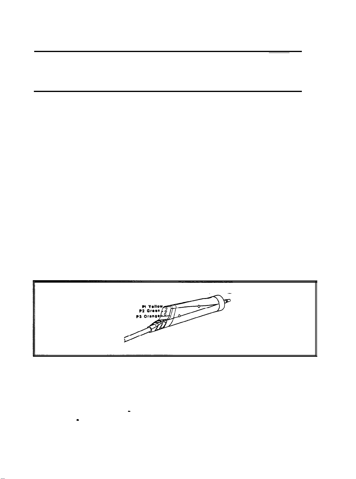
PROBE INDICATORS
The probe indicators are show in Figure
2-1
Figure 2-1: Probe Indicators
PI
Yellow:
the probe is occluded; remove the probe and inspect for cause of
occlusion
P2
Green lamp: blinking
-
GSI 38 Auto Tymps is ready to begin a Tymp; steady
green - test successfully started and in progress.
and a description follows.
P3 Orange:
a pressure leak has been detected.
14
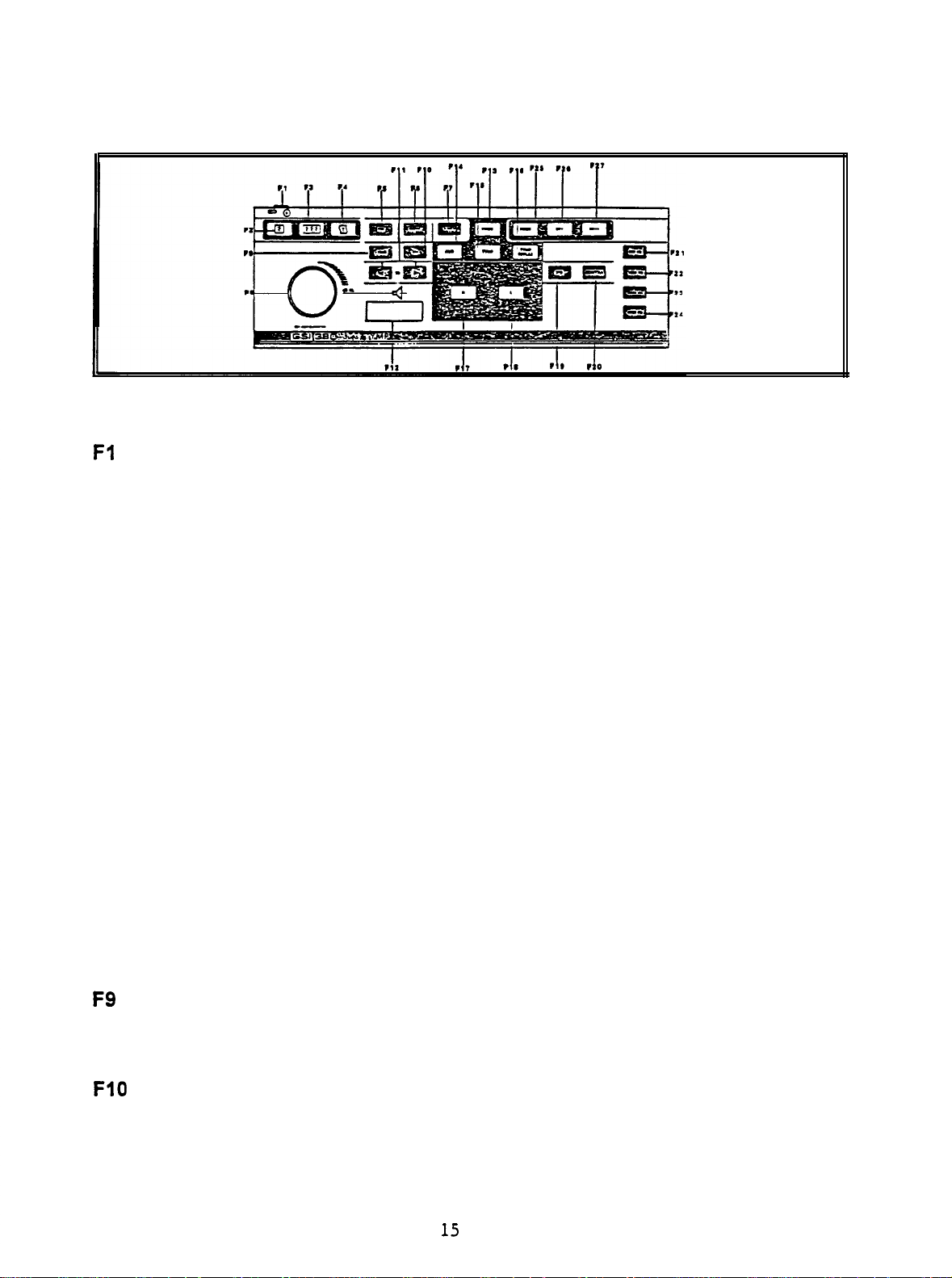
FRONT PANEL CONTROLS AND INDICATORS
Figure 2-2: Front Panel
Fl
F2
F3
F4
F5
F6
F7
F8
Power on indicator and label: indicator is illuminated when the GSI 38 is
receiving power.
Print Screen: pushbutton used to print the currently displayed page of memory.
Print All Memory: used to print all pages of data from memory.
Paper Advance:
causes paper to feed through printer; may be used to load
paper or to provide space between printouts.
FM: used during the Audiometry mode to select a frequency modulated test
tone when the present bar is depressed; causes the letters FM to appear on the
display when selected.
Steady: used during Audiometry mode to select a continuous test tone when
present bar is depressed; causes the steady symbol to appear on the display.
Pulsed: used during Audiometry mode to select a pulsed tone when the present
bar is depressed; causes the pulsed symbol to appear on the display.
(dB
Attenuator Knob
HL): used to increase or decrease the intensity of the
test tone presented in Audiometry mode; counterclockwise rotation causes the
intensity to be lowered; clockwise rotation causes the intensity to be increased.
F9
FlO
dB:
+10
used to temporarily extend the intensity range by 10
dB;
causes a
large + sign to appear on the display indicating that the extended range has
been selected.
M+: save key; during Audiometry mode, causes the threshold information per
frequency to be saved on the display; during Program mode, causes option to
be selected; during Tymp/Reflex mode, causes frequency to be stored as a
default parameter.
15

Fll
<
and > Hz:
selecting
Selecting < causes the cursor to move the next lower frequency;
>
causes the cursor to move to the next higher frequency.
F12
F13
F14
F15
F16
F17
F18
Present Bar:
Push downward to present test signal to appropriate earphone;
release to turn test tone off.
Prog(ram):
press to select Program mode screen which lists setting available
to reflex presentation format, printout header format, audiogram vs. tabular
format, display normal box, and identify frequency range for Audiometry mode.
Aud(iometry):
press to select Audiometry mode. (Available in Versions 3 & 4
only).
TYMP:
Tymp Reflex:
R:
press to select Tympanometry only mode.
press select Tympanometty and Reflex mode.
used to identify right ear under test so that data stored in memory and/or
printed is properly identified; for Versions 3 and 4, used to select right earphone
for audiometry.
L: used to identify left ear under test so that data stored in memory and/or
printed is properly identified: for Versions 3 and 4, used to select
left
earphone
for audiometry.
F19
F20
F21
F22
F23
F24
F25
F26
F27
IPSI:
used to select an ipsilateral reflex test.
to
CONTRA: used
select a contralateral reflex test (available with Versions 2
and 3 only).
Hz
500: selects 500
as a stimulus during reflex testing.
1000: selects 1000 Hz as a stimulus during reflex testing.
2000: selects 2000 Hz as a stimulus during
as
4000: selects 4000 Hz
PAGE:
used to scroll through test results stored in memory.
a stimulus during reflex testing.
reflex
testing.
M-: used to erase currently displayed page of data from memory.
M-:
used to erase all pages of data from memory.
16
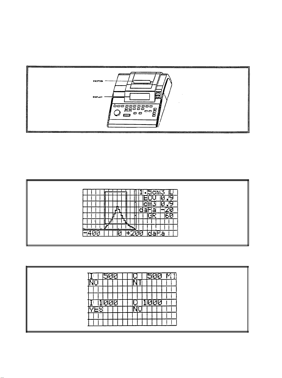
PRINTER AND DISPLAY
The printer cover can be removed to reload paper. See Figure 2-3 for location of the
printer and printer cover. Section 2-7 provides paper loading instructions.
Figure 2-3: Printer and Display
The display indicates test mode, parameters for test and test results. See Figure 2-3
for location of display. Figures 2-4 through 2-8 show the individual display format for
each test mode.
Figure 2-4: Display Format for
TYMP
Only Test
Figure 2-5:Display Format for TYMP/REFLEX Test
(Reflex
test results given as “Yes” or “No”).
17
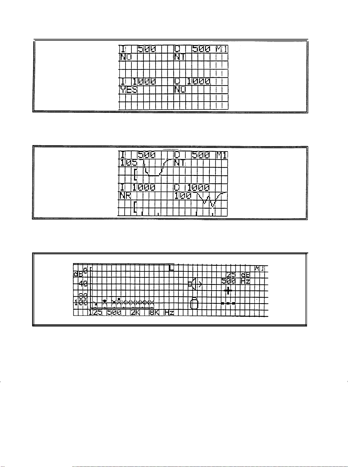
Figure 2-6: Display for
(Reflex test results given in
TYMP/REFLEX
"dB
HL”).
Test
Figure 2-7: Display Format
(Reflex test results given in
Figure 2-8:
REAR AND BOTTOM PANEL
"dB HL"
Display Format for AUDIOMETRY
LABELS/CONNECTORS
The rear panel labels and connectors
each one follows.
TYMP/REFLEX
Test
and also shown with a “tracing”)
are shown in Figure 2-9 and a description of
18
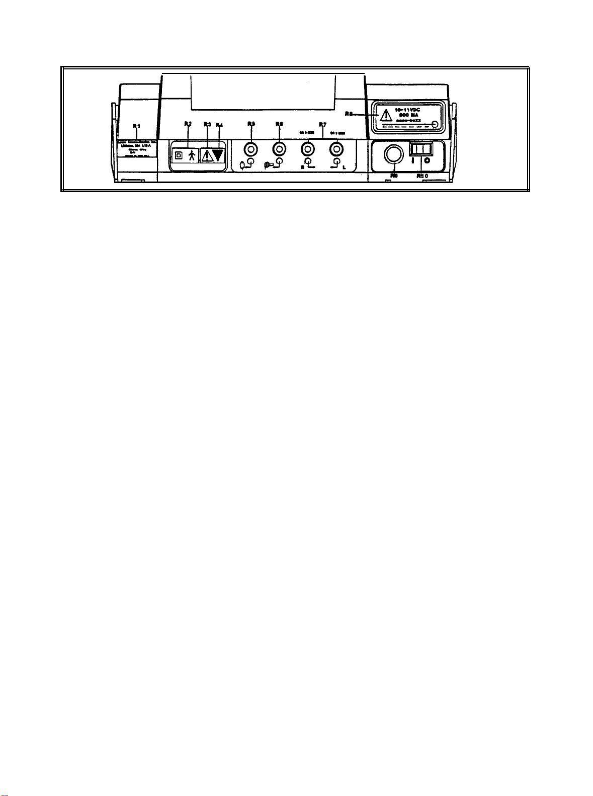
Figure 2-9: Rear Panel
R1
R2
R3
R4
R5
R6
R7
R8
R9
Company name, address, model, serial number and country of origin.
Symbol denotes a
Type B, Class II Product per IEC 878 as referenced in IEC
601 Standard.
Symbol denotes Attention, consult accompanying documents.
Symbol indicates a service adjustment part that is intended for service personnel
use only.
Connector for handswitch. Input impedance -47 k ohm pulls up to 5 volts.
Connector for contralateral insert phone. < 1 ohm, 2.5 volts rms maximum open
circuit.
Connectors for right and left earphone. 130 ohm, 2.50 volts rms maximum open
circuit.
Label describing low input voltage and current from wall mounted power supply.
5-pin
Power Input Jack.
DIN connector for external wall mounted power supply.
RIO
Power Switch with ON/OFF indicators.
NOTE
There is a symbol on the bottom panel that indicates
entry by qualified service personnel only. This symbol
1"
is marked “B
in Figure
19
2-10
Bottom Panel.
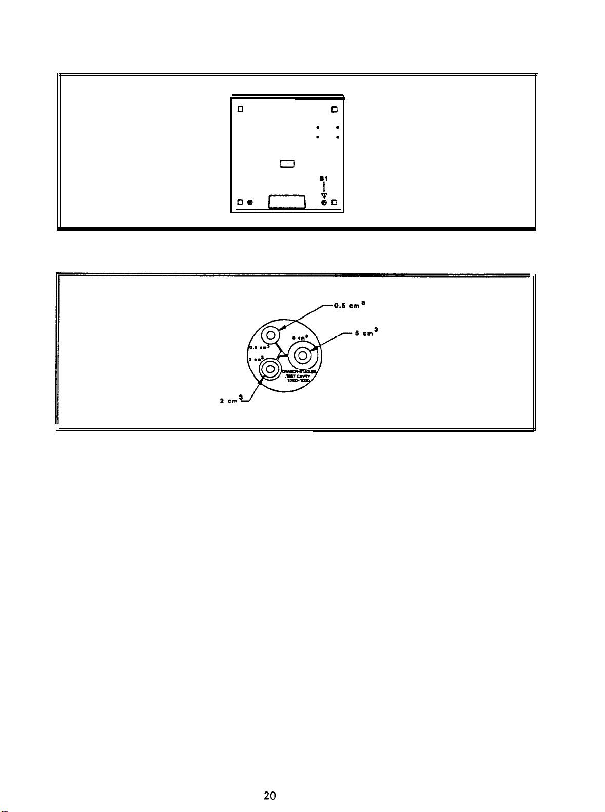
Figure 2-10: Bottom Panel
Figure 2-11: Test Cavity
PRETEST
TYMP
CHECKS
For your convenience, a test cavity is provided with your GSI 38 Auto Tymp. This test
cavity enables you to quickly verify, on a daily basis, the prober calibration of your unit.
GSI strongly recommends that you make this quick check a part of your daily routine.
TYMP CALIBRATION VERIFICATIONS
To initiate the quick check, select the Tymp only mode and insert the probe into the
0.5
cm3 opening on the test cavity. See Figure 2-l 1.
NOTE
Since the
important that the probe is inserted as quickly and as
smoothly as possible. During the calibration check, the
probe must be held carefully and without movement.
Do not place the probe on the same counter as the
instrument or any moving object during this check as
mechanical noise will be picked up by the probe and
interfere with the calibration check.
GSI
38 is designed to start automatically, it is
20

The calibration check will start automatically if the probe has been inserted into the
cavity properly. This is confirmed by the green lamp changing from blinking to a steady
condition. If the orange lamp is illuminated, the probe is not properly positioned within
the cavity so that a large pressure leak exists. If the yellow lamp is illuminated, the
probe tip has been occluded.In either case, remove the probe and wait for the blinking
green lamp. Insert the probe once again. Clean the probe tip if necessary (XXXXXX).
When the test sequence is completed, the green lamp on the probe is no longer
illuminated.
Remove the probe from the test cavity and note that the green lamp is
blinking once again. The display will indicate a flat line on the tympanogram along with
the value of the test cavity next to the letters ECV (ear canal volume) i.e., 0.5. The
letters NP will appear next to the labels
cm3
and
daPa
and three dashed lines will
appear next to the letters GR (gradient). Since the test cavity is a hard-walled cavity,
the tympanogram should be a flat line indicating that there is no mobility in the system.
The GSI 38 places the letters NP next to the
cm3 and
daPa
headers to indicate that
there is no peak compliance and, therefore, no peak pressure can be determined
during the quick check. Also, since there is no compliance peak detected, it is not
possible to calculate a gradient. Therefore, the GSI 38 displays the dashed lines when
a gradient calculation isn’t possible. Using the same sequence, place the probe in the
test cavity opening
0.5
cm3 measurement except for the value placed next to the letters ECV 2.0. If you
wish, the same sequence can be followed with the 5.0
labelled
2.0
cm3
Note that the display looks the same as with the
cm3 opening on the test cavity.
To keep a record of this test cavity calibration check, simply press the print all
pushbutton on the front panel of the GSI 38.
Since sound pressure will vary with altitude and barometric pressure, some variation
3
from the 0.5, 2.0 and 5.0 cm
readings may be observed. Your GSI 38 is carefully
calibrated at our factory which is at approximately 250 feet above sea level. If you are
located at an elevation of 1000 feet or higher, your instrument may need to be
recalibrated to account for your elevation (See Section XXXX). If is not necessary to
recalibrate for barometric pressure changes on a daily basis. Just keep in mind that
a change in barometric pressure (i.e., from low to high or high to low) will slightly affect
the test cavity readings.
ALTITUDE ADJUSTMENT
The Altitude calibration adjustment allows the instrument operator to “correct” the ear
canal volume
(ECV)
measurement and test cavity volume measurement
for variations
due to altitude. Because the GSI 38 is a pressure-sensitive device which makes
measurements relative to ambient air pressure, changes in air pressure due to weather
or altitude will affect the ECV read-out of the instrument. The slight pressure change
resulting from changing weather conditions will usually yield volume read-outs within
+/- 0.1
these cavity values by as much as 30%. These
the accuracy of the compliance measurement system in any way.
cm3
of the expected cavity value, but pressure changes due to altitude can shift
changes in pressure do not affect
However, many
instrument operators prefer that their equipment give ECV values as they would appear
at sea level. The altitude calibration mode allow the operator to adjust his/her Auto
Tymp without the services of a qualified GSI representative.
21
TABLE 2-1 Altitude Correction
-
ALTITUDE CORRECTION
Altitude (ft)
0
-
1,500
2,000-3,500
4,000- 6.000
6.500- 7.600
6.600- 6.000 24+/-
6.500-10,000
---
20
2.1
2.2
2.3
2.5
Altitude
+/-
0.1
+/-
0.1
+/-
0.1
0.1
+/-
0.1
Table (cm3)
The altitude calibration mode can only be entered when the
GSI
38 is powered up from
its “off’ state while the program mode pushbutton, PROG is depressed. Hold the
PROG pushbutton for approximately five seconds.
STEP 1
When entering the altitude mode the display will read as follow:
Altitude Mode
ECV 2.0
cm3 9.99
Standard
(E71) is displayed in the bottom right corner of the display until the probe is in the 2.0
cm3 cavity.
STEP 2
Place the probe into the
2.0cm3 cavity provided with the instrument and check
cm
3
value against the altitude correction table for accuracy.
STEP 3
If the measured volume is not within the published table value
+/-
.1cc, then the
operator should exit the altitude mode by pressing the PROGRAM MODE pushbutton
and contact field service. Providing the measured volume agrees with the published
table
With
+/-
.1cc, the operator may proceed with the altitude adjustment.
STEP 4
the probe still in the 2.0
cm3 cavity, select the page pushbutton to enter the
custom calibration mode. Custom will appear on the fourth line of the display.
22

STEP 5
3
The value now displayed in the c m
to the current altitude.
If the value displayed is 2.0 cc then the volume is adjusted to
the current site. If the value is not 2.0 cc
display area is the volume measured and adjusted
+/- .1,
then press the SAVE pushbutton M+
to customize the volume measurement to the current altitude. The measured volume
should now read 2.0 cc.
STEP 6
To exit the altitude mode press the PROG pushbutton to return to normal mode.
PROGRAM MODE
To enter the program mode, select the
PROGram
pushbutton located on the front
panel. The following screen appears the first time you enter the Program mode after
you receive your GSI 38 from the factory. (in other words, there are the default settings
used at the factory during production).
Program Mode
l
Reflex HL + Curve
Reflex HL only Print - Aud Table
Reflex Yes/No l Normal Box ASHA
* Pm Header GSI
Pm Header Off
Pm Header Custom Aud Range Narrow
Note that these selections. fall into
five
-
User Selections
l Print - Audiogram
Normal Box Off
* Aud Range Normal
different groups of controls:
Reflex format for printer
Print header format
Audiometric test result format
Status of normal box
Audiogram frequency range
The default setting for each group of controls has an asterisk
(*)
before it so that it is
easy to scan the settings selected for each group.
REFLEX FORMAT
Reflex test results can be displayed and printed in three different ways: reflex dB HL
dB
plus curve; reflex
dB
reflex
HL plus curve. This means that all reflex test results will appear on the
HL only; or reflex yes/no. The default setting for this grouping is
display and the printout with the following information.
23

NOTE
If you
the square cursor next to the asterisk
Header custom and press M+ to cause the line
appear
display.The word SAVED will appear at the lower tight
margin indicating that the custom header is still
selected.
had previous/y entered a custom header, position
(*)
in front of Pm
cursor
to
at the left-hand margin along the bottom of the
To move the cursor from the left-hand margin without inserting a letter or number,
select the character which represents a space (i.e., rotate the knob one position to right
of the letter A). Use the > Hz pushbutton to move over to the next character position.
Repeat this sequence until the cursor is moved over to the desired start position for the
first character to appear in your header.
Rotate the
dB
HL knob to select the
appropriate characters to spell out the desired header. After selecting each character,
use the > Hz pushbutton to move over to the next character position. Once all of the
header characters have been added, press the M+ pushbutton to save your header in
memory. The word SAVED will appear on the right-hand margin indicating that you
header is now saved. The square cursor will reappear next to Pm Header Custom.
It is now possible to exit the program mode or to sequence on the next user selection.
To exit the program mode, press the pushbutton labeled PROG. Enter a single test
result and select print screen to see how the custom header looks.
AUDIOMETRIC FORMAT DURING PRINTING
The audiometric test results can be printed out in an audiogram format (PRINT
-
AUDIOGRAM) or in a tabular format (PRINT - AUD TABLE). The default setting for
this function is the audiogram format.
NOTE
When a specific frequency is deselected for testing, the
result will be
frequency.
threshold exists at that untested frequency.
Move the < or > Hz pushbutton
AUD TABLE.
Next, select the M+ pushbutton to save this format as the new default
parameter. Note that the
a break in the audiogram line at that
This eliminates the assumption that a
to
position the cursor in front of the description
word
SAVED appears in the lower right-hand comer of the
PRINT-
display to indicate that this new setting has been saved. With PRINT-AUD TABLE
selected, all audiometric test results will appear in a table with the frequency range
typed horizontally along the top of the table followed by two lines of test data. The test
results for the right ear will appear next to the letter R and below each frequency
tested. Similarly, the test results from the left ear will follow below the right ear results.
24

This setting (PRINT-AUD) selects the format for the
printout only. An audiogram always appears on the
screen while in this mode.
NORMAL BOX FORMAT
NOTE
It is possible to have the normal box, as described by
tympanogram screen and printout. The boundaries for this normal box are -150
to
+100 daPa
and 0.2
cm3 to 1.4
cm3.
ASHA,
appear on the
daPa
NOTE
A compliance value of 7.5
automatically turn off the
ASHA
cm3 or greater will
normal box.
The normal box is the default setting. To deselect this normal box, move the square
cursor with either the < or > Hz so that it is placed in front of the words Normal Box Off.
While the cursor is in this position, select the M+ pushbutton to save this feature as the
new default setting. Note that the word SAVED appears in the lower right-hand margin.
This message assures you that the normal box ill not appear on the tymp screen or
printout.
AUDIOGRAM RANGE
All eleven frequencies are available during audiometry or the range can be abbreviated
to eight frequencies.
The default setting is Aud Range Normal. To select the
abbreviated frequency range, position the square cursor in front of the feature Aud
Range Narrow. Press the M+ pushbutton to save this narrow range for audiometric
testing. Note that the word SAVED will appear in the lower right-hand margin and the
asterisk now appears in front of the narrow range selection. The normal range of
frequencies include 125 Hz through 8000 Hz. The narrow range of frequencies
includes 500 Hz through 6000 Hz. Please note that in the Aud mode, if the narrow
range is selected, the < and > Hz pushbuttons will allow you to scroll through this
abbreviated frequency range only. Both the screen and printout will still be
labelled
with the full range of frequencies. i.e., 125 Hz through 8000 Hz.
EXIT PROGRAM MODE
Exit the program mode by selecting the PROG pushbutton. Note that you return to the
test mode which was operational prior to entering the program mode.
25

TEST IN MEMORY
The Tymp and TympReflex test results
.
test sequence
ends.
Audiometric test
are automatically stored in memory when the
results are stored in memory when the M+
pushbutton is pressed a total of eight memory locations are available with the GSI 38.
Each test result is assigned a memory location number in order of sequence obtained
starting with Ml and continuing up to M8.
To review the individual test results, press the PAGE pushbutton. Note that the screen
contains the appropriate format for each test type stored (e.g., tympanogram or
audiogram). The memory number is located in the upper right-hand corner of each
screen.
If, for example, only five tests were stored in memory, only five memory
locations can be scanned. The memory can be scanned a page at a time by pressing
the PAGE pushbutton once and observing the results. The entire memory can be
scrolled through by holding the PAGE pushbutton down continuously.
MEMORY ERASE
If there is a particular test result that you wish to delete before printing, PAGE to this
test result and press the M- pushbutton. This causes that particular test result to be
erased from memory. The erase mode is accessed when the operator selects a test
to erase and presses the M- pushbutton. The LCD displays a blank screen for erased
memories with the memory location number located at the top right corner. Upon exit
form the erase mode the stored memories reshuffle and replace the empty memory
with the remaining tests in the order in which they were run. The erase mode will be
exited once the operator presses the PRINT ALL or ERASE ALL pushbuttons or any
pushbutton that would normally begin the setup of a new test. Please note that when
the erase mode is entered, a current audiogram is no longer accessible to change or
to store new HL values.
*
NOTE
The instrument is programmed to default to the right ear
dB
at 0
audiometric test.
and 1000 Hz upon selection of a new
If you should wish to erase all tests from memory, press the M-(ERASE ALL)
pushbutton. (For example, the test results have been printed and you wish to test
another person).
NOTE
Be certain that you wish to remove all tests from
M--
memory before pressing the
the erasure
pushbutton!
occurs
immediately upon pressing the
26
pushbutton because
M--

PRINTING TEST RESULTS
The printout will begin with a header if it is selected during the program mode (i.e.,
GSI
38 or a custom header designed by you). The next two lines contain space for entering
the individuals name and the test date. This is followed by the test results in the order
that they were obtained/selected.
Either a single test can be printed from memory or the entire group of tests in memory
can be printed. To print a single test from memory, use the PAGE pushbutton to arrive
at the desired test result to print.
Once this test is displayed, press the PRINT
SCREEN pushbutton.
To print all tests in memory, simply select the PRINT ALL pushbutton. When
PRINT ALL
is pressed and two audiogram tests are stored in memory, they will combine
under the following conditions. There must be one left test and one right test
sequentially stored in memory. A left and right audiometric pair of tests will not be
combined if they are separated in the memory by a tymp test. Therefore, when tests
are erased, the resorting could cause a change in left, right or right, left combined when
PRINT ALL is selected. Prior to selecting PRINT ALL the operator should scroll
through the tests in memory to determine where the audiometric tests are located. This
will help the operator to avoid combining tests from different patients.
27

CIRCUIT THEORY
28

The Microprocessors
GSI
The
38 operation is controlled by two
MC68HC1 1E1
microcontrollers. The
microcontrollers have an 8 bit CPU and additional built in peripheral devices. It was
designed using HCMOS technology which combines smaller size and higher speeds
with the lower power and high noise immunity of CMOS. On chip
bytes of
RAM
and 512 bytes
of EEPROM. The built in peripheral functions include:
memory includes 512
An eight
channel/8
bit analog to digital convertor
A 16 bit timer system
bit
An 8
pulse accumulator circuit
A real time interrupt circuit
Parallel input/output ports
A computer operating properly (COP) watch dog system which protects against
software failures.
A serial peripheral interface (SPI)
A serial communications interface (SCI)
Power saving wait and stop modes
The many functions incorporated by the microcontroller helps to reduce board space
requirements and the need for additional support
circuitry.
The audio microprocessor (U34) is the master of the system and has control over the
tymp microprocessor (U7) which functions
as a slave.
THE AUDIO MICROPROCESSOR CONTROLS THE FOLLOWING FUNCTIONS:
Communication
to the
Tymp
Microprocessor: Asynchronous serial communications
data is transmitted and received using the processors built in serial communications
interface. The interface is located within port D of the microprocessor. PDO is the
receive data (ARXD) line and
PD1
is the transmit data (ATXD) line. The bi-directional
communication allows the transfer of information, test results, parameters and control
functions to occur between the two processors.
Display Drive Information: Display information to and from the liquid crystal display
(LCD) display board RAM is latched via the bi-directional latch (U29). After the
information is loaded into the LCD board RAM the display board drives the associated
pixels and the audioprocessor is free to perform other tasks. The display area is 240
pixels wide by 64 pixels high.
Monitoring of the Switch Matrix Kevs:
The processor routinely checks the status of
the front panel keys for a change in state. The key panel switch inputs buffers U26,
U27, U28 and U31 are read every 24 msec.
processor executes the commands associated with the key function. The
(extended range) key and the reflex control keys (Ipsi, Contra, 500,
If a switch change has occurred the
+10dB
1K, 2K,
4K) are
active toggle controls (ie., push on/push off).
29

Monitoring of the Switch Matrix Keys Continued:
The present bar, subject response switch, frequency up/down key, paper advance key,
and page key all function as press and hold controls where the corresponding function
is active only as long as the control is pressed. Single action controls include the mode
control keys (Prog, Aud, Tymp,
routing keys
(L,R),
memory control keys (Page, M-, M-), and the printer control keys
Tymp/Reflex)
tone type keys (FM, Steady, Pulsed),
(Print Screen, Print All, Paper Advance).
Normal/Calibration
Mode Switch: The slide switch is monitored by the processor thru
the switch input buffer U31. It is utilized for entry to the calibration and diagnostic
modes.
Switches: Dip switches 1 thru 4 are connected directly to the microprocessor
Dip
A/D
convertor. Dip switches 5 thru 8 are connected to the switch input buffer U31. These
dip switch selections are read or processed upon entry to the calibration mode. When
calibration mode is selected the dip switch status is verified and processed according
to the individual selections. Any change in the dip switch status after entry to the
calibration mode will be ignored by the processor.
Hearing
Level Control
(HL):
The hearing level control dial is connected to a 36
position 2 bit encoder (RE1) located on the HL Board. The encoder output from the HL
board is connected to port A of the audio processor. In the audiometer mode this
rotary knob selects the stimulus hearing level based on the relative position change of
the knob from the previous hearing level selection.
30

Pure Tone Stimulus
The Audio microprocessor controls the frequency generator for the associated Left
Earphone, Right Earphone, Ipsilateral, or Contralateral outputs. The foundation of the
pure tone stimulus generator is a Programmable Timer (U24). Output 0
square wave with a
50/50
duty cycle equal to the selected front panel frequency. Out 1
(SQWIN)
is a
(SCFCLK) is a square wave that is either fifty or one hundred times greater than the front
panel frequency and is used to set the band pass of the switched capacitor filter.
Out 2
is tied back to the micro controller IRQ and is used as an interrupt for the microprocessor
)
so that it can update the COP (computer operating properly
The
SQWIN
and minus
signal is a 0 to 5 volt square wave which is level shifted by (U44) to a plus
5
volt square wave. The signal then passes through an anti
eliminates high frequency harmonics and “rounds” the edges of the sine wave.
circuit.
-
aliasing filter that
The signal
then passes through the switched capacitor filter (U49) which reduces harmonics and other
noise. This is the process that produces the clean sine wave product.
Attenuator and +
The attenuator
10dB
Range Extender
(U56)
is a Voltage Controlled Amplifier
(VCA).
This device has
amplification gain but most of its dynamic range is used as an attenuator. The total range
of the attenuator is 112 dB The output of the attenuator may be set to any level within this
range by adjusting the DC voltage present at the EC line pin 3. This input pin is connected
to a Digital to Analog Convertor
(DAC/U53)
that controls the output level of the attenuator.
Calibration of the output levels is accomplished by storing a Hearing Level to Sound
Pressure Level value, per frequency and transducer, in a look up table in EEPROM. This
information is then latched (U25) to the DAC that drives the attenuator to the appropriate
output level.
+10 Range Extender may be selected any time that the hearing level is within 1
The resolution or step size is controllable to within a .5 dB increment. The
0dB
of the
maximum non-extended hearing level for all frequencies. This selection allows an
additional
+10dB
of range above the normal maximum hearing level limit. After the
attenuator but before the routing of the signal to the left or right earphone is the 1 0dB gain
or attenuator circuit. The control line (+1 ODB) that selects the extended range (U51) is
enabled or disabled by the latch
Output Routing
Control
(U20).
The output of the attenuator
Amplifier
(U52),
or the lpsi / Probe Tone
(ATTENOUT)
is routed to either the Left amplifier
Speaker Amplifier
(U66).
When contra is selected
(U48)
Right
the output is routed through the right output amplifier and is then switched to the contra
phone by the routing relay
allows the output to be disabled or shut off to conserve power.
K1.
The output amplifiers have a special control line (pin 1) that
Thispower saving feature
also eliminates any unwanted noise from a non selected output.
31

.
unction I Control
The test results are printed using a thermal print head printer on paper that is
112mm
wide. When the print function is selected the processor starts building a graphical bit
mapped image of the printout in the Audio RAM (U32). The printout is formatted as
specified by the selections made in the program mode and stored in EEPROM. Before
printing takes place the A/D port E of the micro controller measures the ambient
temperature and adds it to the calibrated Dot on time stored in EEPROM. This routine
assures consistent print quality regardless of the ambient temperature or the print head
resistance.
The serial print data is transferred from the RAM through port D of the micro controller to
&
the serial to parallel convertor (U19). The dot drivers (U16
U19
sink the current through the associated print head dot element. Information for the
U17) that are connected to
print head motor driver (U15) and the paper feed motor driver (U14) is received from the
micro controller port A. The latch (U13) assures that the print head dot drivers are off
when the print head motor is inactive or when the paper feed motor is advanced. The
printer has a built in switch that is closed when the print head is returned to the home
position.
During the power up initialization and after each print out the print head motor
is returned to the home position. The printer also has independent power supplies used
for the print head
(U38/
V
+5P)
and the print motors
(U39/
+VM). The +VM power supply
is also connected to the left right routing relay Kl.
32

The Tymp
.
Microp
rocessor controls the
following
functions:
Communication to the Audio
transmitted and received using the processors built in serial communications interface.
The interface is located within port D of the microprocessor.
line
(TRXD)
communication allows the transfer of information, test results, parameters, and control
functions to occur between the two processors.
Pump Drive Control: The
a piston, and an infra photo eye/detector pair. After power-up (during the instrument
initialization period) and at the end of a test the pump piston is returned to the home
position. The home position (HOME) is determined by a state transition of the infra red
photo detector of the pump assembly which is monitored by the Tymp microprocessor
(U7) A/D input PE4 (pin 44). The pump motor coils are driven by the motor driver (U37)
which is clocked by the pump drive timer (U21). The timer controls the step rate of the
pump assembly which varies with the pressure sweep rate. The pump sweeps at a rate
of 600
to 200
probe is removed from the ear canal. When the probe is removed from the ear canal the
pump returns to the home position.
Monitoring
monitored by the Tymp Microprocessor (U7) A/D input PE6 (pin 48).
Pressure calibration mode the CMOS Switch
pressure transducer circuit so that the input voltage at the
gain adjustment places the pressure transducer output at ambient or zero pressure in the
optimum operating range for the A/D convertor. When the ambient gain has been
established the processor will set the switches to the stored values at all times. The
pressure span calibration
microprocessor as a software offset.
daPa/sec
and
daPa/sec.
of the Pressure Transducer Output ; The pressure Transducer output is
PD1
is the Tymp transmit data line (TTXD). The bidirectional
until the slope of the tympanogram is sensed then the sweep rate slows
If a leak is detected during the pump sweep the pump stops until the
(+200/-400)
Microprocessor; Asynchronous communications data is
PDO is the Tymp receive data
Pump assembly consists of a DC step motor, an air reservoir,
In the Ambient
(U64)
is used to adjust the gain of the
A/D
is equal to 1.5 vdc. This
is controlled by the technician and is stored by the
;
Probe Tone Oscillator (226 Hz) and Speaker Drive
generated by the Microprocessor (U7) Internal Timer System (Port A). This produces a
226 Hz Square wave at PA3 of the Tymp Microprocessor (U7 pin 31). The Square wave
level or gain
switches select the appropriate output levels based on controls from the microprocessor.
The output levels or switch settings are determined by the calibration data and the external
volume as measured by the probe microphone. The appropriate level is then routed
through a 226 Hz band pass filter (U61). The signal is then routed to the Probe Tone / lpsi
speaker amp (U66).
Microphone
ear canal must be filtered to remove as much unwanted signal as possible. This filtering
is
determined by the CMOS switch settings of (U45 and (U46). These
Input level Monitoring ; The microphone signals that are measured in the
33
The Probe tone Frequency is

is performed by the 226 Hz band pass filter (U65). The filtered RMS microphone signal
rectified
is
is
level adjusted (U59) by the Microprocessor to establish an optimum operating range for
to a dc level for input to the Microprocessor A/D convertor.
This filtered signal
the system during the tymp sweep or reflex testing.
34

CALIBRATION
35

EQUIPMENT REQUIRED FOR CALIBRATION
TYPE 1 SOUND LEVEL METER
ARTIFICIAL EAR
2 cc COUPLER (GSI #1700-2005 OR B&K #DB0138)
9A
(6 cc) COUPLER OR B&K ARTIFICIAL EAR (B&K #4153)
MANOMETER
VOLTMETER (RMS)
FREQUENCY COUNTER
1700-l 030 TEST CAVITY
SMALL STANDARD (SLOTTED) SCREWDRIVER
SMALL PHILLIPS (CROSS) SCREWDRIVER
36

CALIBRATION PROCEDURE
CONFIG.
Confiq.
mode of operation and once programmed should never change. If a new
microprocessor is installed in location XU7 or
programmed. To program the
JP1
and JP3 then power up the unit. Almost immediately after power up the unit will
display
previously installed jumpers. The
DEFAULT DATA LOADING: Durina routine calibration it is not
Default Data.
set of calibration values into EEPROM. Also, if a new microprocessor has been
installed the Default Data loads critical power-up information that the processor requires
for operation into EEPROM. When a new microprocessor or
installed Default Data should be loaded. Load Default Data by setting Dip Switch
positions 6, 7, and 8 to the “ON” position. Set the
then power up the unit. At power-up the display should indicate the unit model and
version number (GSI 38 Version X), the
(Tymp/Reflex
XXX), and the Default Parameters which are currently being loaded into EEPROM
(Loading Audiometer Defautts, Loading Programmed Defautts, or Loading
Defaults). When the Default Data Loading sequence is complete the display will update
to the Main Calibration Mode Menu. At this point Dip Switches 6, 7, and 8 should be
returned to their normally OFF position.
REGISTER: Durinq routine Calibration it is not
Register.
Config.
Programming the
Register Programmed. At this point power down and remove the
Defautt Data Loading
Rev XXX), the Audiometer Software Revision Number (Audiometer Rev
Config.
Config.
Config.
allows
Register establishes the microprocessors
XU34
Register install temporary jumpers (shorts) on
Register is now programmed.
the
technician
Cal/Norm
Tymp/Reflex
necessary
its
Config.
to quickly store an
Switch to the Cal Mode,
Software Revision Number
to
program
Register must be
necessary
Auto/Tymp
to
averaged
Board is
Tymp/Reflex
the
load
The technician may also load an individual set of Default Data by first setting the
desired Dip Switch to the ON position then setting the Cal/Norm Switch to the Cal
Mode position.Dip Switch assignments are as follows:
Dip Switch
6
7
8
Function
Tymp/Reflex
Audiometer Defaults
Programmed Defaults
Defaults
37
Location Loaded
Tymp EEPROM
Audio EEPROM
Audio EEPROM

‘..
NTERING
THE CALIBRATION MODE DIRECTLY (ROUTINE CALIBRATION)
1)
2)
3)
Verify that Dip Switches 6, 7, and 8 are in the OFF position.
Power up the unit.
Slide the Cal/Normal Switch to the Cal Mode position. The display should
appear as follows:
7
CALIBRATION MODES
l
ATTEN
XDUCER
MAX CAL
STIM
CAL
PRINT HEAD CAL
CUSTOM RTL CAL
PROBE
TONE/MIC
CAL
COMPLIANCE CAL
PRESSURE CAL
38

AUDIOMETER CALIBRATION
ATTENUATOR MAXIMUM OUTPUT CALIBRATION: During routine calibration it
should not be necessary to calibrate the Attenuator Maximum Output. However, if
Audiometer Default Data has been loaded then the Attenuator Maximum Output
must be calibrated.
the
1)
2)
3)
4)
5)
Connect the right phone output unloaded
Use the
ATTEN
Press the Present Bar
(The Tone Indicator
Use the
the dB HL knob until the output level for currently display frequency is within the
minimum/maximum values listed in the following table. When the desired output
level has been reached store the value by pressing the pi Key. Repeat
all frequencies.
!=I
MAX CAL
p/
Hz
Hz
Frequencv
125
250
500
750
1000
1500
2000
3000
4000
6000
8000
[c]
F)
Keys to position the cursor on the 38 display at the
position.
Key
to enter the
0
to lock on the tone.
*
should now be present on the display.
to select the desired frequency for calibration.
(Hz)
.
to
an RMS Meter.
ATTEN
MAX CAL Mode.
Minimum - Maximum
2.05-2.30
2.05-2.30
2.33
-
2.5
1.69-1.9
2.28-2.5 vrms
2.28 -
2.55 -
2.28 -
2.55 -
2.28-2.50
2.28 -
2.5
2.70
2.50 vrms
2.70 vrms
2.50 vrms
vrms
vrms
vrms
vrms
vrms
vrrns
vrms
Adjust
for
After all frequencies have been calibrated press the
Calibration Mode Menu.
39
v]
Key to the Main

AUDIOMETER
Use
1)
the a IHz[m IKeys
STIM CAL.
SPL OUTPUT LEVEL CALIBRATION
to position
the cursor on the
38
display at XDUCER
2)
Press
the
I=]
Key to
enter the XDUCER
STIM
CAL
MODE.
The display should now indicate:
XDUCER
STIM
CAL
40.0
125
dB
Hz
NOTE: Tone Bar is OFF
or Inactive
R
40.0
125 Hz
R
dB
Indicates the Current Hearing Level (HL) selected.
Indicates the Current Frequency (Hz) selected.
Indicates the Current Transducer selected.
Indicates a Steady Tone Presentation
The Tone Bar is active in this mode and serves a dual function. When the Tone Bar
as
is OFF or inactive the current hearing level is displayed
When the Tone Bar is pressed ON or active the stim on indicator
the display and the 40.0
dB
(HL) indicator will update
to
shown above.
will appear on
*
the ANSI Standard Reference
Threshold Level (RTL) measured in Sound Pressure Level (SPL) for the selected
frequency and hearing level.
Example:
40.0 dB (HL) at 125 Hz (Freq) will update to 85.0 dB SPL
when the Tone Bar is depressed.
Given:
Therefore:
The ANSI Standard (RTL) correction value for 125 Hz at 0 HL is
dB
equal to 45.0
At 40 dB HL which
Hz
125
will equal 85.0 dB SPL.
SPL.
is
For 125 Hz
ANSI Standard RTL for 0 dB HL
(+)40
dB HL
dB
40
HL
.
40 dB SPL higher that 0 dB HL the output for
=
=
=
40
45.0 dB SPL
(+)40.0 dB
85.0 dB SPL
SPL

For 8
KHz
When calibrating using a Sound Level Meter (SLM) it is important to add or subtract the
appropriate microphone correction.
manufacturer or calibration facility should supply the microphone’s frequency response
curve.
response by using a piston phone or similar standard device. Below is an example of
a microphone frequency response curve.
MICROPHONE
CALIBRATION
ANSI Standard RTL for 0. dB HL
(+)60 dB
dB
60.
HL
HL
=
=
=
13.0 dB SPL
(+)
60.0 dB SPL
73.0 dB SPL
When the microphones are calibrated the
The microphone is then calibrated to the SLM which has a flat frequency
l
CHART
5
dB
+1
0
-1
-5
Provo,
Utah
-10
. .._,..., .q , , ,
I
-15
20 Hz 50 1DO
.,-_i..,
! I. ._ ! i, _
.I 11 1
._,‘_.,.., 1,. __, _,._ ,
200 ' 500
1K
2K
5K
10K
--1-\I--s’
20K
50K
The curve shows that the microphone response is flat between 20 Hz and 1.5 KHz,
KHz
high between 2
as
an example when a standard force is applied to the surface of this microphone its
dB
output is 1
1 dB to our expected value. Our formula for determining the proper calibration
add
high. Therefore, when calibrating 4
and 6
KHz,
and low at frequencies 8 KHz or greater. Using 4 KHz
KHz
using this microphone we must
level for 4 KHz is as follows:
100k'
200K
. 41

4
KHz
ANSI Standard RTL for
Reference HL for Calibration
(+)80. dB
(+) or (-) Microphone Correction
0. dB HL
NA.
80.
dB
=
HL
=
HL
=
(+)80.0 dB
(+)
9.5 dB SPL
SPL
1.0 dB SPL
90.5 dB SPL
The following table contains the ANSI Standard Reference Threshold Levels
RTL's
at
0 HL for each frequency when using TDH-39P earphones.
Frequency (Hz)
ANSI Standardd
Measured
in dB SPL
RTL
125
45.0 25.5
Standard Reference Threshold Levels re:
250
11.5
500 750 1000 1500
7.5
20pPa
7.0 6.5
for
Telephonics
2000 3000
9.0
10.0
TDH-39P earphones
4000
0.5
as measured on the National Bureau of Standards 9-A coupler. Reference ANSI S3.6
6000 8000
15.5 13.0
-
1989, ISO 389 - 1975 Standards.
Grason-Stadler has made an effort to minimize calibration time by defaulting the
Reference HL Levels for Calibration to maintain an expected SPL Calibration Level of
between 85 and 95 dB SPL. The Default HL Levels are as follows:
Frequency
Default HL
(Hz)
125 250 500 750 1000 1500
40
60 80 80 80 80
2000 3000
80 80 80 80 60
4000
6000
8000
Because the 38 automatically adds the ANSI RTL and reference HL values on the
display (when the Tone Bar, is active) the technician needs only to add or subtract
the appropriate microphone correction to the displayed value when calibrating.
3)
4)
5)
Connect the right ear phone to the Sound Level Meter Artificial Ear.
Press (TONE BAR\ the display will update from the selected hearing level to
the ANSI Standard RTL value for calibration and the
appear).
indicator will
m+
Adjust the HL knob until the SPL Level measured on the SLM for the selected
frequency and transducer equals the value indicated on the 38 display (+ or
’
-
Microphone Correction).
6)
7)
Press
Repeat for all frequencies, right phone, left phone, ipsi and contra by
theIF
Key to store the data in memory.
selecting the appropriate key on the 38 front panel.
NOTE: Both left phone and right phone must be calibrated.
-
8)
When finished press the
Menu.
vl
Key to return to the Main Calibration Mode

CUSTOM RTL CAL
This mode is used primarily if a customer wants to calibrate using transducers other
than TDH-39P earphones. This mode allows the technician to program different
RTL values to be displayed when calibrating using the XDUCER
Once programmed, the Custom RTL values will be displayed each time the
XDUCER
dB
63.5
Audiometry Mode is selected to indicate to the customer that Custom RTL values
have been programmed. To return to the ANSI Standard Values and extinguish the
#
sign, the technician must load Audiometry Default Calibration Data.
1)
STIM
CAL MODE is entered. The range of allowable
A # sign will appear next to the dB HL indicator on the display when
Use
theF]Hz]=]Keys
display.
to position the cursor at Custom RTL Cal on the
STIM
CAL MODE.
RTL's
is -5 dB to
2)
3)
4)
5)
6)
7)
NOTE:
PROBE
Press the
Press
Adjust the dB HL dial to achieve the desired RTL value.
Store the value into memory by pressing the m Key.
Repeat for all desired frequencies.
Press
Use
Mode
IFZF]
thewlHz[c]Keys
the
]w]
Adjusting the Custom RTL values has no effect on the earphone
output level. After storing the Custom
must calibrate to the appropriate levels using the XDUCER
CAL MODE.
TONE/MIC
theI=] HzF]Key
position.
CAL
Key to enter the Custom RTL Cal Mode.
to select the desired frequency.
Key to return to the Main Calibration Menu.
RTL's
to position the cursor at the Probe
the technician
Tone/Mic
STIM
Cal
2)
Press the ) PROG 1 Key to enter Probe Tone/Mic Cal Mode. The display will
update to the following “flashing” display.
PROBE
ECV
At this point place the probe in the 2 cc coupler on the Sound Level Meter.
TONE/MIC
SLM
CAL 1.1
43

3)
Press the
m
Key and the display will stop flashing.
4)
5)
6)
Use the dB HL dial to adjust the Probe Tone Level to 85.5 dB SPL
dB).
At this point the Probe Tone
226 Hz
Press the
(+/-
6 Hz).
LM+f
Key to store the data in memory. The display will update to
Frequency
may be verified. It should equal
the following ‘Washing” display.
j:l’:,‘““““*“‘I
.
At this
Press the
point
place the probe in the 2 cc test cavity.
m
Key to start the microphone calibration process. The display
will update to the following steady state display.
**I
(+/-
0.9
After a few seconds the SAVED indicator will extinguish and the 1.2
will change to 1.3. When the cycle is complete the display
following “flashing” display.
7)
,
Press the
~
-
COMPLIANCE CAL
1)
Use the
F]
Mode position.
2)
Press the
[=I
update to the following “flashing” display.
Hz
will update to the
Key to return to the Main Calibration Mode Menu.
-
LqKeys
to position the cursor
Key to enter the Compliance
at the Compliance Cal
Cal Model The display will
indicator
44

COMPLIANCE CAL 2.1
ECV 0.5
3
cm
3)
4)
Place the probe into the 0.5 cc calibration cavity then press the
[M+I
Key to
start the 0.5 cc calibration. The display will stop flashing and remain in steady
state to indicate that calibration is in progress.
NOTE: If the wrong cavity size is used the display will indicate E74 in the lower
right hand corner. After approximately 5 seconds the ERROR MESSAGE will
extinguish and the calibration process may be continued by placing the probe
into 0.5 cc cavity and then pressing the
[WI
Key.
When the 0.5 cc calibration is complete the display will update to the following
“flashing” display.
COMPLIANCE CAL 2.2
ECV 2.0
3
cm
At this point place the probe into the 2.0 cc test cavity.
Press the
PI
Key to start the 2.0 cc calibration. The display will stop flashing
and remain in steady state to indicate that calibration is in progress.
NOTE: If the wrong cavity size is used the display will indicate E74 in the lower
right hand corner.
After approximately 5 seconds the ERROR
MESSAGE
extinguish and the calibration process may be continued by placing the probe
into the 2.0 cc cavity and then pressing the
m]
Key.
When the 2.0 cc calibration process is complete the display will update to the
following steady state display.
COMPLIANCE CAL 2.3
ECV 2.0
cm3
X.XX
X.XX
is equal to the current volume measurement.
.
45

The calibration of compliance measuring devices is affected by air density. As
the air gets thinner, the volume measurement in a
hardwall
cavity increases.
Therefore, as you go up in altitude, barometric pressure decreases making the
hardwall
cavity appear larger than it is.The GSI 38 allows the flexibility to
display the real altitude effect or to correct the ear canal measurements relative
to sea level.
A)
If the customer prefers to correct the ear canal volumes relative to sea
level then adjust
2.00 After adjusting to the desired level store the value by pressing
the
]m
compliance calibration process is complete.
B)
If the customer prefers uncorrected ear canal volumes (actual at altitude
measurements) then adjust the
value indicates the appropriate volume measurement for the customer site
elevation according to the following altitude table.
Altitude
(ft)
0
500
1000
1500
2000
2500
3000
3500
4000
4500
5000
5500
6000
6500
7000
7500
8000
8500
9000
9500
10000
Barometric Pressure
(mm
thep]HzlF]
Keys until the cm3 XXX value equals
Key. The display will start “flashing” indicating that the
i-1
Hz
[Fj
Keys until the cm’ XXX
Expected Volume Reading
Hg)
759.97
746.51
733.04
719.84
706.63
693.93
681.23
668.78
656.34
644.40
632.46
620.78
609.09
598.00
588.00
578.00
568.00
555.00
544.00
533.00
522.00
*
at Altitude (cc)
2.00
2.01
2.03
2.05
2.07
2.09
2.11
2.13
2.15
2.17
2.20
2.22
2.25
2.27
2.30
2.34
2.37 2.4~0.1
2.40
2.44
2.49 2.520.1
2.54
Calibration Volume
at
Altitude
(cc)
2.0
2.020.1
2.020.1
2.020.1
2.120.1
2.120.1
2.120.1
2.120.1
2.2zo.q
2.220.1
2.220.1
2.220.1
2.220.1
2.3~O.q
2.3~0.1
2.320.1
2.4~0.1
2.4~0.1
2.520.1
5)
Press the
]M+j
Key to store the customer altitude volume measurement. The
display will start “flashing” indicating that the Compliance Calibration process is
complete.
Press the
m]
Key to return to the Main Calibration Mode Menu.
46

PRESSURE CAL
1)
2)
3)
Use the
Press the
update to the following “flashing” display.
At this point make sure that the probe tip is in open air.
Press
Pressure Calibration is complete the display will update to the following “flashing”
display.
[~~Hz~~~
I-1
I
1
M+ 1 Key to start the Ambient Pressure Calibration.
Keys to position the
Key
to enter the Pressure
‘PRESSURE CAL
ECV OPEN
A/D
daPa
cursorr
at the Pressure Cal position.
Cal Mode. The display will
3.1
When the
Ambient
.
PRESSURE
ECV MANOMETER
A/D
XXXX
daPa
-200
CAL
3.2
4)
5)
6)
At this point connect the probe tip to a manometer.
NOTE: Manometer internal volume must be less than 5 cc’s.
Press the
Use the
to -200
Press the
saved will appear in the lower right hand corner of the display. After 3 to 5
seconds the saved indicator will be extinguished and the display will update to
a steady state display as follows.
At this point verify that the leak rate is less than 2
Press the
manometer reading is within &15%) of the pressure value indicated on the 38
display.
Press the
-1
IzIHz
daPa &15%)
wi
1-1
Ver
/=I
Key. At this point the pump will pressurize to -200
[=I
Key to store the -200
Key and the 38 will pressurize to +200
Key to return to the Main Calibration Mode Menu.
daPa
.
Keys to adjust the pressure on the external manometer
daPa
Calibration data. The messages
daPa/sec:
daPa.
47

PRINT HEAD CAL
1)
2)
3)
Use the
Press
Press the
1x1 HzLG]
the
-1
[=I
Keys to move the cursor at the Print Head Cal position.
Key to enter the Print Head Cal Mode.
Hz to lighten
the
printout and the
[=I
Hz Key to darken the
printout. When either key is pressed the printer will print a test pattern (the
alphabet) on a single line. When the center of the adjustment range is crossed
the In Range indicator on the display will appear (when adjusting from a light
intensity to a dark intensity) or extinguish (when adjusting from a dark intensity
to a light intensity).
EXAMPLE
TOTAL RANGE
OF PRINT INTENSITY ADJUST RANGE.
=
20 STEPS OR 20 DIFFERENT INTENSITY LEVELS.
ABCDEFGHIJKLMNOPQRSTUVWXYZ:
ABCDEFGHIJKLMNOPQRSTUVWXYZ:
ABCDEFGHIJKLMNOPQRSTUVWXYZ:
ABCDEFGHIJKLMNOPQRSTUVWXYZ:
ABCDEFGHIJKLMNOPQRSTUVWXYZ:
ABCDEFGHIJKLMNOPQRSTUVWXYZ:
ABCDEFGHIJKLRNOPQRSTUVWXYZ:
ABCDEFGHIJKLRNOPQRSTUVWXYZ:
ABCDEFGHIJKLMNOPQRSTUVWXYZ:
ABCDEFGHIJKLMNOPQRSTUVWXYZ:
l ABCDEFGHIJKLNNOPQRSTUVWXYZ:
l ABCDEFGHIJKLMNOPQRSTUVWXYZ:
l ABCDEFGHIJKLMHOPQRSTUVWXYZ:
l
ABCDEFGHIJKLMNOPQRSTUVWXYZ;
l ABCDEFGHIJKLMNOPQRSTUVWXYZ:
l ABCDEFGHIJKLMNOPQRSTUVWXYZ:
l ABCDEFGHIJKLMNOPQRSTUVWXYZ:
l ABCDEFGHIJKLMNOPQRSTUVWXYZ:
lABCDEFGHIJKLMNOPQRSTUVWXYZ:
l ABCDEFGHIJKLMNOPQRSTUVWXYZ:
l “In Range” indicated on display.
4)
5)
6)
Press
Press the
Slide the Cal/Norm Switch to Norm to return to Normal Mode Operation.
the[F]
1-1
Key to store the desired intensity value.
Key to return to the Main Cal Mode Menu.
. 48

S4 DIP SWITCHES.
S1
S2
S3
S4 _
S5
S6
S7
S8
Unused
Factory Auto
To Be Defined
To Be Defined
To Be Defined
Tymp/Reflex Default Data
Audiometer
Program Default Data
ON
Cal
Default
Data
Unused
Norma! Cal Mode Operation
Normal Cal Mode Operation
Normal Cal Mode Operation
Normal Cal Mode Operation
Normal Cal Mode Operation
Normal Cal Mode Operation
Normal Cal Mode Operationon
*
OFF
49

TROUBLE SHOOTING
50

ERROR MESSAGES (EXX)
NOTE: If an Error Message is observed the associated code number should be
recorded for future reference.
specific block of circuitry which will enable the technician to repair the problem in a fast,
efficient manner. Most software errors are related to poor environmental conditions
such
as static electricity and power line interference and will generally clear with power
down/up. Contact your local sales and service organization and supply them with the
Error Code Number if the error will not clear with power down/up.
AUDIOMETER PROCESSOR RELATED MESSAGES
The Error Code Number is designed to point to a
Code Number
EPROM Checksum Error on power up / if
01
02
03
04
05
Description/Possible
non-recoverable possible defective
Board EPROM
Microprocessor Internal RAM Error on power up / if nonrecoverable replace Microprocessor U34.
Watch Dog Timer Timeout / the Watch Dog Timer Circuit
monitors the Microprocessor’s operation. The Processor
must periodically send an “I’m Okay” message ‘to the watch
dog or the watch dog will halt all operations. If nonrecoverable try replacing.
Audiomymp Board.
Microprocessor
defective crystal Y2 or Microprocessor U34.
Undefined Interrupt Error / this type of soft error should
always be recoverable.
Processor does not acknowledge or cannot execute. If nonrecoverable replace Audiomymp Board.
U30
Clock Failure / if non-recoverable possible
Cause
Auto/Tymp
or Microprocessor U34.
Microprocessor U34 or
It
relates to an Interrupt that the
06
07
08
Opcode Trap Interrupt Error /this type of error code should
always be recoverable.
Microprocessor
External
Audio RAM U32 or Microprocessor
Normal or Swap Stack
should always be recoverable.
Audio/Tymp Board.
RAM
U34
or Audiomymp Board.
Error / if non-recoverable possible defective
Overflow
51
If non-recoverable replace
U34.
into the Global Variables
If
non-recoverable replace
/

Code Number
Description/Probable Cause
09
10
'12
‘13
'14
'15
Conf. Register Error / if non-recoverable re-calibrate
Config,
Register then replace Microprocessor U34.
Halt in Response to Remote Command
/
if non-recoverable
possible defective Audio/Tymp Communications Chip U36
or Microprocessor
Invalid
Keycode
U34.
detected in CMDTSK / if non-recoverable
possible defective Switch Panel, Switch Buffer U26, U27, or
U28, or Microprocessor U34.
Invalid
Invalid
Keysource detected in CMDTSK
Queue Power
Error detected in CMDTSK /same as
/
same as above.
above.
Bad Pointer to EEPROM Routine’/
Collision of the Normal Stack and Swap
Stack
/
‘16
‘17
'18
'19
‘20
‘21
22
Invalid function for a Banded Swapped Function
Printer RAM Error on power up / internal or micro
Tymp Hardware State is unknown
Non-Fatal Audiometer related error messages
Calibration Data Read Error
HL Limit exceeded /
Invalid Extended Range Selection due to HL not in range
where the Extend Range is valid
23
24
Calibration Data Write Error occurred
Invalid Present Bar Operation due to a
Calibration Data Error /
/
/
occured /
/
/
52

Code Number
Description/Probable Cause
25
Remote Record received with a Bad Record Format, invalid
Key Code, or Invalid Record Type
26
27
28
EEPROM Checksum Error
EPROM TO EEPROM Data Load Error
Remote Command received from an external remote device
(factory auto
unsupported record type
29
Remote command received from an external remote device
(factory auto cal) which is ignored due to mode
30
GSI vs Custom RTL Calibration status Read Error from
EEPROM
31
32
Printer Calibration Data Read Error
No test available to print
/
/
/
cal)
which is invalid due to mode or is an
/
/
/
/
/
33
34
35
36
37
38
39
40
Tymp/Reflex
the Audio Processor or the
setting the Synch
No Free Memory available when going to a new test
Processor not responding to a command from
Tymp/Reflex
Processor is not
Stimo line on power up /
/
Invalid test type read from memory when trying to display
Print Head initialization failed /
Printer Ambient temperature out of Range
Record was received from the
Tymp/Reflex
/
Processor which
has a valid format but the record type was not the type
expected
/
Call Factory for instruction
Audiometry mode not enabled

TYMP
PROCESSOR RELATED MESSAGES
Code Number
51
52
53
54
55
56
57
58
59
60
Description/Probable Cause
EPROM Checksum Error on power up
Internal RAM Error on power up
Watch Dog Timer Time Out
CPU Clock Failure
Undefined Interrupt Error
/
/
Opcode Trap Interrupt Error
External RAM Error
Stack Overflow Error
Config.
Register Error
/
/
/
Bad Pointer to EEPROM Routine
/
/
/
/
/
61
62
63-69
70
71
72
73
74
75
EEPROM Read Error in Norm or
Couldn’t Home Pump
/
Alt
Mode
/
Undefined
Non Fatal Errors
Probe is occluded or in cavity at power up
/
Probe not in 2.0 mL cavity during Altitude Adjustment Cal
Mode
End of gain reached in Microphone Cal Mode
/
Probe Tone Gain Error during Probe Tone Gain Verification
/
Cavity Error during Calibration /
Compliance Calibration Error /
76
Unused
54

Code Number
77
Description/Probable Cause
A/D
Pressure Value out of range of Pressure Transducer
Gain
Error /
78
79
80
Remote Record Error
Non-Fatal Cal Data
Reflex Test
time /
81
82
83
84
Remote Command invalid for the mode
Leak or Occlusion Error
Pump end of stroke
Undefined Error Number Reported /
/
Read/Write
info
not received for the Audio within the allotted
Error
/
/
/
/
55

DISASSEMBLY
56

CAUTION STATIC SENSITIVE DEVICES/USE STATIC PROTECTION
DISASSEMBLY
OPENING CASE
TO GAIN ACCESS TO INTERNAL
UNDER FRONT EDGE OF UNIT AS SHOWN IN
STABILIZE
REMOVING SCREWS
TO REMOVE PROBE
DISCONNECT REAR PANEL POWER CONNECTOR. OPEN CASE. DISCONNECT AUDIO/TYMP
BOARD CONNECTORS
PUMP PNEUMATIC
REMOVE CABLE CLAMP SCREW
DETAIL VIEW “A”. GENTLY LIFT THE CABLE STRAIN RELIEF OUT OF THE
PANEL.
TO REMOVE HL BOARD ASSEMBLY
DISCONNECT REAR PANEL POWER CONNECTOR. REMOVE HL KNOB AND THE HL SWITCH
MOUNTING HARDWARE (7116” HEX NUT
REMOVE SCREW MARKED
TOP CASE.
TO REMOVE
DISCONNECT ALL REAR PANEL CONNECTORS OPEN CASE. DISCONNECT
CONNECTORS
"B"
AS SHOWN IN
CASE.
UNIT
AND LOCATE COMPONENTS IF UNIT IS PLACED ON LER SIDE PRIOR TO
AND
OPENING CASE.
J8
AND SHIELD 1. DISCONNECT THE PNEUMATIC TUBING FROM THE
FITTING
AUDIO/TYMP
J2
THRU J8 AND SHIELD 1
DRAWING
BY GENTLY PULLING ON TUBING NEAR THE PNEUMATIC FITTING.
BOARD
COMPONENTS.
MARKED"C"
&
WASHER) AS SHOWN IN DRAWING 2. OPEN CASE.
"D" AS
SHOWN IN DRAWING 1. GENTLY
(ie
1. PULL BOARD CAREFULLY FORWARD THEN UP AND OUT OF
REMOVE
DRAWING 1.
AS SHOWN IN
ALL). LOOSEN OR REMOVE 2 SCREWS MARKED
2 SCREWS
NOTE: IT MAY BE EASIER TO
DRAWING 1
MARKED “A” LOCATED
AND ENLARGED
BOTTOM
LIFT
BOARD AWAY FROM
AUTO/TYMP
CASE SIDE
BOARD
TO REMOVE TIP-UP FEET
DISCONNECT REAR PANEL POWER CONNECTOR. OPEN CASE. REMOVE SCREWS MARKED
"E"
AS SHOWN IN DRAWING 1 AND DRAWING 2.
57


SWITCH PANEL REMOVAL
DISCONNECT REAR PANEL POWER CONNECTOR. REMOVE HL KNOB. OPEN CASE.
DISCONNECT AUDIO/TYMP BOARD CONNECTOR
WHICH SECURES THE SWITCH PANEL CABLE BY GRASPING FIRMLY AND GENTLY PULLING
AWAY FROM THE
ADHESIVE BACKING. START LIFTING THE SWITCH PANEL BY INSERTING A SMALL KNIFE
BLADE BETWEEN THE SWITCH PANEL AND TOP CASE AT ANY CORNER. ONCE A CORNER
IS LIFTED GRASP THE PANEL FIRMLY AND GENTLY PEEL AWAY FROM THE TOP CASE.
PRINTER REMOVAL
TOP COVER.
THE SWITCH PANEL IS SECURED TO THE TOP COVER BY
J4.
REMOVE THE ADHESIVE CABLE CLAMP
DISCONNECT ALL REAR PANEL CONNECTORS. OPEN CASE. REMOVE
DISCONNECT J1 AND J2 FROM PRINTER CONNECTOR BOARD. REMOVE PAPER COVER.
REMOVE 2 SCREWS MARKED
REMOVE PRINTER BY LIFTING REAR OF PRINTER ABOVE THE 2 REAR HOLDING PINS OF
CASE, THEN SLIDE PRINTER TOWARDS THE REAR UNTIL THE PRINTER IS CLEAR OF THE 2
FRONT HOLDING PINS. ONCE CLEAR OF THE HOLDING PINS
PRINTER CONNECTOR BOARD REMOVAL
DISCONNECT ALL REAR PANEL CONNECTORS. OPEN CASE. REMOVE AUDIO/TYMP BOARD.
DISCONNECT Jl & J2 FROM PRINTER CONNECTOR BOARD. REMOVE SCREW MARKED
AS SHOWN IN
LCD REMOVAL
DISCONNECT ALL REAR PANEL CONNECTORS. OPEN CASE. REMOVE
REMOVE 4 SCREWS MARKED
.250
INCHES LONG. INSTALLING LONGER SCREWS WILL CAUSE SCREWS TO PROTRUDE
THROUGH FRONT PANEL!).
PUMP REMOVAL
DISCONNECT REAR PANEL POWER CONNECTOR. OPEN CASE. DISCONNECT J7
AUDIO/TYMP BOARD. DISCONNECT PNEUMATIC TUBING FROM PUMP FITTING. REMOVE 4
SCREWS MARKED
SCREWS WILL BE EASIER IF
PRESSURE WHILE LIFTING PUMP FROM CASE TO ALLOW PUMP TO CLEAR SHOCK MOUNT
STANDOFFS.
DRAWING 3.
"K"
AS SHOWN IN DRAWING 3 AND DRAWING 5. NOTE: ACCESS TO PUMP
"F"
AS SHOWN IN
"H"
AS SHOWN IN DRAWING 3. (NOTE: THESE SCREWS ARE
BOTTOM
CASE IS REMOVED. APPLY SLIGHT REARWARD
DRAWING
4. REMOVE PRINTER COVER.
LIFT
AUDIO/TYMP
PRINTER OUT OF CASE.
AUDIO/TYMP
BOARD.
BOARD.
& J8
FROM
"G"
BOTTOM CASE REMOVAL
DISCONNECT REAR PANEL POWER CONNECTOR. OPEN CASE. LOOSEN 4 SCREWS MARKED
"L"
AS SHOWN IN DRAWING 1 BY APPROXIMATELY 3 TURNS. THIS SHOULD ALLOW
SUFFICIENT CLEARANCE TO SLIDE
AND THE HINGE BLOCKS.
BOTTOM
CASE PINS
60
FROM BETWEEN THE TOP COVER

INSTRUMENT ASSEMBLY PARTS LIST
DESCRIPTION
INSTRUMENT ASSEMBLY, GSI 38
CONSISTING OF:
LABEL SET,
CASE, BOTTOM
KNOB, CONTROL
GOUND PLANE, ESD PROTECT
PRINTER,
SWITCH PANEL,
LABEL, JACK PANEL
ASSEMBLY, CASE, TOP
ASSEMBLY, LIQUID CRYSTAL DISPLAY
ASSEMBLY, PROBE 1738-3200
ASSEMBLY, PUMP .
ASSEMBLY, AUDIO/TYMP BD.
ASSEMBLY, PRINTER CONNECTOR BD.
ASSEMBLY, H.L. BD.
LENS, DISPLAY 1738-7002
COVER, PAPER 1738-7020
SUPPORT, PUMP
COVER, CALIBRATION 1738-7042
BLOCK,
PANEL, POWER, BLANK 1738-7060
PANEL, POWER 1738-7065
COVER, PRINTER
CLAMP, CABLE, FIAT, ADHESIVE
CLAMP, INSULATING,
RETAINER, KNOB
FOOT, ADHESIVE, BLACK 5260-2250
SHOCK MOUNT, MALE-FEMALE
GROMMET 5680-l 001
SCREW, LOCKING,
STANDOFF, M/F 7574-0050
FOOT,
NUT, LOCKING, #6-32
SCREW, PAN HD.,
SCREW, LOCKING,
TI
GSI
38
112mm,
HINGE
P-UP 5260-3800
HIGH SPEED
GSI
38
.25
NOM. I.D.
#6-32
x
.375
LG.
36-32
x
.500
LG.
#6-32
x
.250
LG.
PART NUMBER
1738-3100
1738-0480
1717-7001
1717-7006
1738-042 1
1738-0430
1738-0435
1738-0440
1738-1005
1738-l 010
1738-3210
1738-4705
1738-4710
1738-4715
1738-704 1
1738-7055
1738-7080
4314-0009
4320-0300
5220-0101
5680-0305
7044-0037
5814-0003
7044-1203
7044-0024
61

AUDIO/TYMP
BOARD
ASSEMBLY DRAWINGS/SCHEMATICS
62


AUDIO/TYMP
BOARD PARTS LIST
DESIGNATION
INTEGRATED CIRCUITS
U1
U2
U3
U4
U5
U6
U7
U8
U9
U10
U11
U12
U13
U14
U15
U16
U17
U18
U19
U20
U21
U22
U23
U24
U25
,,-‘- U26-U28
U29
U30
U31
U32
U33
U34
U35
\
U36
‘i
U37
U38
i,
U39
DESCRIPTION
IC,
SMT, 74 HC 4075, 3 INPUT OR
IC,
SMT, 74 HCOO, QUAD 2
IC, SMT, 74 HC02, QUAD 2 INPUT NOR
IC,
SMT, MC 34064, UNDER VOLTAGE SENSOR
IC, SMT, MC 14053,
IC, SMT,
IC,
SMT,
EPROM, PROGRAMMED
IC, SMT, 6264, 8K X 8 STATIC RAM
IC, SMT, 74 HC 373, 3 STATE OCTAL LATCH
IC, SMT, 74 HC 273, OCTAL D FLIP-FLOP
SEE Ull
IC, SMT 74 HC 4538, DUAL MULTIVIBRATOR
IC, MC 3479, STEP MOTOR DRIVER
SEE U14
IC, SN 754377, QUAD PERIPHERAL DRIVER
SEE U16
SEE U2
IC,
SMT, 74 HC 595, 8 BIT I/O SHIFT REG.
SEE
IC, MC 6840, PROGRAMMABLE TIMER
IC, SMT, 74 HC 10, 3 INPUT NAND
SEE
IC, SMT, 82 C 54, PROGRAMMABLE
SEE Ull
IC, SMT, 74 HC 541, OCTAL BUFFER/DRIVER
IC, SMT, 74 HC 245, 3 STATE BUS X-CIEVER
EPROM PROGRAMMED
SEE U26 - U28
IC,
SMT, MS 62256,
IC, SMT, CMOSPAL, PROGRAMMED
SEE U7
IC,
SMT, LT 1054, VOLTAGE
SEE U5
SEE U14
IC, MC 7805,
IC,
LM
74HCC138,
68HC11E1,
U11
U10
+5V
317, REGULATOR
TR1-2
1 OF 8
8 BIT MICRO
32KX8,
REG
INPUT
NAND
CH
MUX/DEMUX
DECODE/DEMUX
TIMER
STATIC RAM
CONV/REG
PART
5905-4075
5905-0000
5905-0002
59334064
5904-4053
5905-0138
1738-0510
5904-6264
5905-0373
5905-0273
5905-4538
5431-9697
5431-9697
5909-0595
5431-9018
5905-0010
5929-8254
5905-054
5905-0245
1738-0505
5904-2256
1738-0515
5908-l 054
5432-l 066
5432-l 024
NUMBER
1
72

DESIGNATION DESCRIPTION
PART NUMBER
INTEGRATED CIRCUITS CONTINUED...
U40
U41
U43
U44
SEE U38
IC, SMT, MC
79L05,
-5V REG
IC, SMT, TL072, JFET OP AMP
IC, SMT,
LT1013,
DUAL OP AMP
U45 IC, SMT, 140518, ANALOG MULTI PLXR
U46
U47
U48
U49
U50 - U51
U52
U53
U54
U55
U56
U57
U58
U59
U60
U61 - U62
U63 - U64
U65
U66
U67
U68
U69
SEE U45
SEE U5
IC, SMT, MC 34119, LOW POWER AUD. AMP
IC, SMT,
LTC1060CS,
SWITCHED CAP FILTER
SEE U5
SEE U48
IC, SMT, AD7524, 8 BIT D/A CONVERTER
SEE U5
IC, SMT,
IC,
SEE
IC,
SMT. AD736.
SEE
SR25D, 2.5V
DBX2150,
VC AMP
U44
U45
REF
RMS/DC
CONVERTER
SEE U44
SEE U43
SEE U5
SEE U43
SEE U48
SEE U43
SEE U5
SEE U44
5908-7905
5909-0072
5909-1013
5904-4051
5904-4 119
5904-l 060
5907-7524
5933-0025
5432-l 092
5907-0736
DIODES
CR1 - CR3 DIODE, SMT,
CR4
CR5 - CR6
DIODE,
SEE CR1
MMB0914L
ZENER, 1N759A,
-
CR3
RESISTORS & POTENTIOMETERS
Rl RES, SMT, 1K, 1%,
R2
R3
R4 - R5
R6
R7
R8
R9
R10
Rll - R13
R14
R15
RES, SMT,
RES, SMT, 249 OHM,
RES, SMT, 26.1K, 1%,
RES, SMT,
RES, SMT, 750 OHM, 1%,
SEE R2
SEE R6
RES, SMT,
RES, SMT,
RES, SMT, 130 OHM, 1%,
SEE
R10
47.5K,
20K,
1%,
2M, 1%, .12W
10.2K,
.12W
1%,
.12W
1%, .12W
.12W
.12W
1%, 12W
73
12v
.12W
.12W
6082-2002
6083-1014
6650-l 100
6650-2475
6650-0249
6650-2261
6650-2200
6650-0750
6650-4200
6650-2102
6650-0130

DESIGNATION
DESCRIPTION
RESISTORS 8 POTENTIOMETERS
PART NUMBER
R16
R17
R18
R19
R20
R21 - R22
R23
R24
R25
R26
R27
R28
R29
R30
R31
R32
R33
R34
R35
R36
R37 - R38
R39
R40
R41
R42
R43
R44
R45
R46
R47
R48
R49
R50
R51
R52
R53
R54
R55
R56
R57
R58 - R59
R60 - R61
R62 - R63
R64
R65
R66
R67
R68
R69
THERMISTOR,
SEE
R1
SEE Rll
-
R13
10K, 10%, 4.41%/C
SEE Rl
SEE
R11 -
R13
SEE
R1
SEE R22
SEE
R1
RES, SMT,
SEE
R1
RES, SMT,
24.9K,
64.9K,
1%,
1%,
.12W
.12W
SEE R6
SEE R27
THERMISTOR, SMT,
RES, SMT,
23.2K,
18,
100K,
.12W
10%
SEE R7
SEE R2
RES, SMT,
RES, SMT,
SEE
R11 -
2.49K,
61.9K,
R13
1%,
1%,
.12W
.12W
SEE R6
RES, SMT,
SEE
R11 -
RES, FILM, 332 OHM,
2.05K,
R13
1%,
.12W
1%, .25W
SEE R3
RES, SMT,
102K,
1%,
.12W
SEE R43
RES, SMT,
6.19K,
1%,
.12W
‘SEE R35
SEE R45
SEE R43
SEE R3
SEE R43
SEE R35
SEE R43
SEE Rll - R13
RES, SMT,
191K,
1%,
.12W
SEE R6
SEE
R1
SEE R43
SEE
R11 -
R13
SEE Rl
SEE R14
RES, SMT, 20 OHMS,
1%, .12W
SEE Rll - R13
SEE R34
SEE R39
RES, WW, TEMP. SENS, l.lK 3600 PPM, 5%
SEE R6
6740-l 302
6650-2249
6650-2649
6740-l 350
6650-2232
6650-1249
6650-2619
6650-l 205
6350-0332
6650-3102
6650-1619
6650-3191
6650-9200
6700-0002
74

DESIGNATION
RESISTORS 8 POTENTIOMETERS
R70 SEE R14
R72
R73
R74
R75 - R76
R77
R78
R79 - R81
R82
R83 SEE R14
R84
R85
R86
R87 SEE R74
R88
R89
R90
R91
R92
R93
R94
R95
R96 SEE R4
R97
R98
R99
R100
R101 - R102
R103
R104 - R105
R106
R107
R108
R109
R110
Rlll
Rl12
R115
R116 SEE R7
R150
R151
R200
R201
R202
DESCRIPTION
POT, CER MET, 1K OHM,
POT, CER MET, 50 K,
RES, SMT,
SEE R14
SEE R43
SEE Rll - R13
SEE R6
SEE R39
SEE
R25
SEE R43
SEE R34
SEE R43
RES, SMT,
SEE R43
SEE R34
SEE R25
SEE R2
SEE R35
SEE R34
SEE R39
SEE R85
SEE R2
RES, SMT,
SEE R74
‘SEE R6
SEE R74
SEE
R11 -
RES, SMT, 13.3 OHMS,
SEE
R107
RES, SMT,
SEE R25
SEE R43
SEE R64
SEE Rl
POT, CER MET,
SEE
R1
SEE R7
SEE Rll - R13
SEE R34
40.2K,
15.4K,
8.25,
R13
150K,
1%,
1%,
1%,
.12W
1%,
.12W
10K, +/-
+/-
+/-
10%
.12W
.12W
1%, .12W
20%
10%
PART NUMBER
6049-0500
6049-0350
6650-2402
6650-2154
6650-l 825
6650-9133
6650-3150
6049-0386
75

DESIGNATION
CAPACITORS
DESCRIPTION
PART NUMBER
Cl
C2
C4
C5
C7 - C8
C9
Cl0
C11
Cl2
Cl3
Cl4
Cl5
Cl6
Cl7
-
C24
C25
C27
C28
C29
C30
-
C35
C36
C37
C39
-
C40
C41
C42-C46
C47
C48-C49
C50
C51
C52
C53
C54
C55
C56
C57
C58 - C59
C60
C61
C62
C63
C64
C65
C66
C67 - C69
C70
C71
-
c73
C74
C75 - C76
C77
C78 - C79
CAP, ELECT,
CAP, SMT, CER, 01uF, 10%, 50V
SEE C2
CAP, SMT, CER,
SEE C2
CAP, SMT, TANT,
SEE C2
SEE C5
SEE C2
CAP, SMT, CER
SEE Cl3
SEE C2
CAP, SMT, CER, .01uF, 10%, 50V
SEE C2
SEE C2
CAP, SMT, CER,
CAP, TANT,
SEE Cl3
CAP, SMT, TANT,
SEE C2
SEE
C9
SEE C2
CAP, SMT, TANT,
SEE C2
SEE C50
SEE C25
SEE
C50
SEE C37
SEE C2
SEE C37
SEE C2
CAP ELECT,
SEE C2
CAP, SMT, TANT,
SEE C2
SEE
C50
CAP, SMT, TANT,
SEE C37
SEE C2
SEE C36
SEE C2
CAP,
SMT,
SEE C2
SEE C36
SEE C2
4700uF, 20%, 16V
.47uF, 20%,
1.0uF, 20%,
1000PF, 5%,
AXAL
LEAD,
.47uF,
4.7uF,
2200uF, 20%,
47uF, 20%, 10V
22uF,
10%, 20V
CER,
.0047uF,
50V
35V
50V
100uF, 20%,
10%, 35V
10%, 25V
25V
10%, 50V
16V
4450-6311
4500-l 041
4500-4742
4550-l 052
4500-l 301
4500-l 025
4450-4515
4550-474 1
4550-4751
4450-6310
4550-4762
4550-2261
4550-4721
76

DESIGNATION
CAPACITORS
DESCRIPTION
PART NUMBER
C80
C81
C82 - C84
C85
C86
- c95
C96
c97
C98
C99 -
C100
C101
Cl02
-
Cl04
C105
Cl06
Cl07
C108
Cl09
Cl10
Cl11
Cl12
Cl13
- C116
C117
C118
Cl19
Cl20
Cl21
-
123
Cl24
Cl25
Cl26
Cl27
Cl28
C129 Cl32
Cl34 - C139
Cl40
Cl45
C200
C201
C202
C721
C131
-
Cl33
-
Cl46
CAP, SMT, CER,
CAP, SMT, TANT,
SEE C2
SEE C25
SEE C2
SEE C25
SEE
C5
SEE
C50
SEE C2
SEE
C50
SEE C2
CAP, SMT, CER,
SEE
C5
CAP, SMT, CER,
SEE C2
SEE C36
CAP, SMT, TANT,
SEE
C50
SEE C2
CAP, POLYPROP,
SEE C2
SEE C25
SEE
C80
SEE C25
SEE Cl13 - C116
SEE C2
SEE C25
SEE C2
SEE C25
SEE Cl05
SEE C2
SEE C36
SEE C25
SEE C74
SEE C2
SEE C25
SEE
C9
CAP, SMT, CER,
SEE C113
-
C116
.047uF, 10%,
2.2uF,
10%, 20V
33pF, 5%,
.022uF, 10%,
.22uF,
.047uF, 5%,
.0033uF, 10%,
50V
10%, 35V
50V
50V
50V
50V
4500-4731
4550-2251
4500-3305
4500-2231
4550-2241
4862-2807
4500-3321
RESISTOR NETWORK
RP1
RP2
RP3 - RP4
RP5
RP6 - RP7
RP8 -
RP9
RES, NETWORK, SMT, 47K PULL-UP
RES, NETWORK, SMT,
SEE
RP1
SEE RP2
SEE RP1
RES, NETWORK, SMT, 100 OHM SERIES
77
10K
PULL-UP
6740-2012
6740-2011
6740-2010

DESIGNATION
RESISTOR NETWORK
DESCRIPTION
PART NUMBER
RP10
RP12
RP13
RP14
RP15
:
RP17
SEE RP1
RES, NETWORK, SMT, CUSTOM X 15
RES, NETWORK, SMT, CUSTOM X 8
RES, NETWORK, SMT, CUSTOM X 8
RES, NETWORK, SMT, CUSTOM X 8
SEE RP1
6740-20 13
6740-2016
6740-2015
6740-2014
TRANSDUCERS
Q1
Q2
Q3
XSTR, SMT, MMBT 3904, NPN
XSTR,
SEE
Q1
2N222,
NPN
8214-1035
8210-1222
SWITCHES
S2
S3
S4
SWITCH, POWER 7874-0030
SWITCH, SLIDE, DPDT, RT. ANGLE 7874-0175
SWITCH, DIP, 8 POS, RT. ANGLE
7874-0169
MISCELANEOUS
Jl
J2
J3
J4 (30 PINS)
J5
J6
J7
J8
J9
J10 -
J13
J14
JP1 - JP3
TP1- TP15
Y1 -Y2
Kl
XY1
-
XY2
XU7
XU8
XU30
XU34
POST HEADER ASSEMBLY, 4 POSITION
HEADER, 10 PIN, RT ANGLE, LKG
HEADER, 30 PIN, RT ANGLE, LKG
CONN., STRIP, MALE, RT ANGLE
HEADER, 20 PIN, RT ANGLE, LKG
HEADER, SHROUDED, 1 ROW, 4 PIN
‘HEADER, SHROUDED, 1 ROW, 6 PIN
HEADER, RT. ANGLE, 2MM SP, 12 POSITION
CONN., MALE, JACK, 5 PIN DIN
JACK, PHONE, PC MTG, LOW PROFILE
CONN., RT ANGLE, TELE., 6 CONTACT
CONN., STRIP, SIP, 36 CONT.
JUMPER, TEST POINT,
.020
DIA
CRYSTAL, 4.00 MH2
RELAY, SPST,
9V
INSULATION, CRYSTAL
SOCKET, SMT, LOW PROFILE, PLCC52
SOCKET, SMT, LOW PROFILE, PLCC32
SEE XU8
SEE XU7
CONN., STRIP, RT ANGLE, 1 PIN
4230-3201
4230-7310
4230-7330
4230-7052
4230-7320
4230-2204
4230-2206
4230-l 540
4230-4025
4214-0155
4230-4031
4230-8069
5080-0001
5075-0045
6090-l 530
7574-02 10
7574-l 052
7574-l 032
42304633
SHIELD 1
HEATSINK, 16 PIN DIP SLIDE
-
ON
HEATSINK, TO-220
NUT, HEX, LOCKING,
SCREW, FIL. HD. INS,
SPACER, INS,
.437"
#6-32
.138
X 32 X 1.5 LG
LG
5415-3016
5415-2005
5814-0003
7137-0160
7574-0015
78

PROBE
79


PROBE ASSEMBLY PARTS LIST
DESIGNATION
PROBE BOARD PARTS LIST
DESCRIPTION
ASSEMBLY, PROBE
CONSISTING OF:
WIRE, CLEANING
ASSEMBLY,
NOSECONE, THREADED
ASSEMBLY, PROBE CABLE
ASSEMBLY, PROBE BOARD
CASE, PROBE,
CASE, PROBE, RIGHT
TUBING,
TUBING,
O-RING,
SCREW, SOCKET CAP, #2-56 x
CLAMP, INSULATED
SCREW, FIAT HEAD, #1-42 x
NOSECONE
LEFT
TYGON, .062
TYGON, .125
5/8
ID,
3/4
OD
ID x .5 LG
ID x .5 LG.
3/16, TYPE
.187
LG.
23
PART NUMBER
1738-3200
1737-0430
1737-201
1737-6004
1738-1000
1738-4700
1738-7025
1738-7030
0028-7576
0028-7577
5855-0010
7044-0950
4314-0033
7044-200
0
J
d
1
DESIGNATION DESCRIPTION
INTERGRATED CIRCUITS
U1
RESISTORS
R1
R2
R3
R4
R5
R6
R7
R8
IC, SMT, LM346, PRG
RES, SMT, 1K OHM,
RES, SMT,
RES, SMT,
RES, SMT, 20K OHM, 1%,
RES, SMT,
RES,
RES, SMT,
RES, SMT,
8.25K
40.2K
26.1K
SMT,
130 OHM, 1%,
191K
10.2K
1UAD
OP-AMP
1%, .12W
OHM,
OHM,
OHM,
OHM,
OHM,
83
1%, .12W
1%, .12W
.12W
1%, .12W
.12W
1%,.12W
1%,
12W
PART NUMBER
5909-0346
6650-0110
6650-l 825
6650-2402
6650-2200
6650-2261
6650-0130
6650-3191
6650-2102

DESIGNATION
RESISTORS CONTINUED
DESCRIPTION
PART NUMBER
R9
R10
R11
R12
R13
SEE
SEE R3
RES, SMT, 243K OHM,
SEE R6
RES, SMT, 2 M OHM,
CAPACITORS
Cl
c2
c3
C4
C5
- C8
C9 -
Cl0
Cl1
Cl2
-
Cl6
CR1
CR2
CR3
CAP, SMT, CER,
CAP, SMT,
CAP, SMT, CER, 1uF,
SEE Cl
SEE C3
SEE Cl
CAP, SMT, CER,
SEE Cl
LED, GREEN,
LED, ORANGE,
LED, YELLOW,
HEADER
R1
TANT
.130
.130
.130
1%, .12W
1%, .12W
.01uF,
10% 50V
47
uF, 20%, 10V
10%,
.0033uF,
DIA
DIA
DIA
35V
10%, 50V
6650-3242
6650-4200
4500-l 031
4550-4762
.
4550-l 041
4550-3321
6084-l 071
6084-l 070
6084-l 072
Jl
J2 - J3
CONNECTOR STRIP
MISCELLANEOUS
X2
SR1 -
SR2
HEADER, DBL - ROW, 2 MMSP, 12 POS
‘TERMINAL,
WIRE
WRAPPING
CONN. STRIP, RT. ANGLE, 1 PIN
TANSDUCER, PRESSURE
SEE X2
4230-l 540
7924-0061
4230-4633
1738-0427
84

NOSECONE
“0’‘-RING PARTS LIST
DESIGNATION
KIT, GREASE, "O"-RING
NOSECONE, THREADED
W-RING
DESCRIPTION
KIT, NOSECONE, W-RING, GREASE
CONSISTING OF:
G
PART NUMBER
1738-9605
1738-9610
1737-6004
5855-0010
85

PUMP
86


PRINTER
88


PRINTER CONNECTION BOARD PARTS LIST
DESIGNATION
J1
J2
DESCRIPTION
ASSEMBLY, PRINTER CONNTECTOR BD.
CONSISTING OF:
ASSEMBLY, CABLE, PRINTER-CONN. BD.
PRINTER CONNECTOR BOARD
CONN, FIAT CABLE, 20 CONTACT
CONN., FIAT CABLE, 4 CONTACT
PART NUMBER
1738-4710
1738-0205
1738-0710
4230-1620
4230-1604
90

DISPLAY
91


LIQUID CRYSTAL DISPLAY PARTS LIST
DESIGNATION
ASSEMBLY, LIQUID CRYSTAL DISPLAY
ASSEMBLY, CABLE, LCD 1738-0200
DESCRIPTION
CONSISTING OF: 1738-1010
DISPLAY, LIQUID CRYSTAL, 240 X 64
PART NUMBER
5437-1238
93

ASSEMBLY
94

ASSEMBLY CONTRA PHONE PARTS LIST
QUANTITY
X
1
1
1
ASSEMBLY TDH-39 TEST HEAD SET
DESCRIPTION
INSERT PHONE ASSEMBLY 8000-0079
CONSISTING OF:
CABLE, COAXIAL, 6’ 4204-0209
EARPHONE (AUDIOVOX) 470 ohm 8000-0037
EARTIP,
MODIFIED
PART NUMBER
8000-0255
PARTS LIST
QUANTITY
X
1
2
1
2
ASSEMBLY, HEAD SET CONSISTING
DESCRIPTION
OF:
HEADBAND.
EARPHONE, 60 ohm, PLASTIC TDH-39
CORD, HEAD SET, DUAL
CUSHION, EARPHONE,
MX41
95
PART NUMBER
8000-0175
8000-0142
8000-0046
4204-0147
8000-0143
 Loading...