

Graseby BCI 3301 Service manual
OXIMETER
OPERATION/SERVICE MANUAL
%SpO
2
bpm
CATALOG NUMBER 1818E
ERSION 7, JUNE 2002
V
OPYRIGHT BCI, INC. - 2002
C


Table of Contents
Oximeter Operation/Service Manual
Chapter 1: Introduction 1-1
About This Manual ........................................................................................ 1-1
Proprietary Notice.......................................................................................... 1-1
WARRANTY ................................................................................................1-1
Limited Warranty........................................................................................ 1-1
Disclaimer of Warranties ............................................................................1-2
Conditions of Warranty............................................................................... 1-2
Limitation of Remedies............................................................................... 1-2
Warranty Procedure ....................................................................................1-2
CE Notice....................................................................................................... 1-3
Symbol Definition.......................................................................................... 1-3
2 Warnings, Cautions, & Notes ...................................................................1-4
Chapter 2: Oximeter Features 2-1
Intended Use .................................................................................................. 2-1
Features.......................................................................................................... 2-1
Description of Controls & Features ............................................................... 2-2
Chapter 3: Theory of Operation 3-1
Chapter 4: Using the Oximeter 4-1
Unpack the Oximeter ..................................................................................... 4-1
Install the Batteries ........................................................................................ 4-1
Installing or Replacing the Batteries ........................................................... 4-2
Care and Handling of Sensor ......................................................................... 4-3
Choose the Sensor.......................................................................................... 4-4
Attach the Sensor to the Patient ..................................................................... 4-5
Clean or Disinfect the Sensors .................................................................... 4-5
Finger Sensor for Adult or Pediatric Finger................................................ 4-5
Attach the Sensor to the Oximeter ................................................................. 4-6
Measuring the Patient’s % SpO
Patient Numbers and Spot Check Data .......................................................... 4-8
Manually Incrementing the Patient Number ............................................... 4-8
Clearing All Spot Check Data..................................................................... 4-8
Low Battery Indicator .................................................................................... 4-8
Turning Off the Oximeter .............................................................................. 4-9
Checking the Oximeter’s Performance .......................................................... 4-9
and Pulse Rate ........................................... 4-6
2
Operation/Service Manual i

Table of Contents
Chapter 5: Printer 5-1
Description..................................................................................................... 5-1
Compatible Printers .......................................................................................5-2
What You’ll Need for Printing ...................................................................... 5-2
Setting Up the Oximeter and the Printer........................................................ 5-3
Data Log Printouts ......................................................................................... 5-4
Spot Check Printouts...................................................................................... 5-5
Collecting Spot Check Data........................................................................ 5-5
Manually Incrementing the Patient Number ............................................... 5-5
Clearing All Spot Check Data..................................................................... 5-5
About the Oximeter’s Batteries and Spot Check Data................................ 5-5
Printing Spot Check Data............................................................................ 5-6
Chapter 6: Computer Interface 6-1
Description..................................................................................................... 6-1
Equipment Required ......................................................................................6-1
Computer Interface Instructions..................................................................... 6-1
Chapter 7: Operator’s Maintenance 7-1
Batteries .........................................................................................................7-1
Disposal of batteries and rechargeable batteries ......................................... 7-1
Sensors........................................................................................................... 7-1
Reusable Sensors......................................................................................... 7-1
Disposable Sensors .....................................................................................7-2
Cleaning the Oximeter’s Surfaces.................................................................. 7-2
Long Term Storage ........................................................................................ 7-2
Chapter 8: Operator’s Troubleshooting Chart 8-1
EMI Interference............................................................................................ 8-3
Chapter 9: Optional Supplies & Accessories 9-1
Ordering Information:.................................................................................... 9-1
Chapter 10: Specifications 10-1
Equipment Classification ............................................................................. 10-1
Displays, Indicators, & Keys .......................................................................10-1
............................................................................................................. 10-1
SpO
2
Pulse Rate .................................................................................................... 10-2
Auxiliary Printer Output .............................................................................. 10-2
Power Requirements .................................................................................... 10-2
Battery Life .................................................................................................. 10-2
Dimensions ..................................................................................................10-2
Environmental Specifications ...................................................................... 10-2
ii Operation/Service Manual

Table of Contents
Chapter 11: Service Maintenance & Repair 11-1
General Description ..................................................................................... 11-1
Oximeter On/Off Control............................................................................. 11-1
Power Supplies ............................................................................................ 11-2
Microprocessor Circuit ................................................................................11-2
Reset Circuit.............................................................................................. 11-3
Memory and I/O Decoding .......................................................................11-3
Addressable Latch.....................................................................................11-4
ON Key Decode........................................................................................ 11-4
Synchronous Serial Port............................................................................ 11-4
Asynchronous Serial Port.......................................................................... 11-5
Speaker Output.......................................................................................... 11-5
Analog Demultiplexer.................................................................................. 11-5
A/D Converter.............................................................................................. 11-6
LED Drive.................................................................................................... 11-6
Signal Processing......................................................................................... 11-6
Display Board ..............................................................................................11-7
Signal Dictionary ......................................................................................... 11-7
Oximeter Board......................................................................................... 11-7
Display Board .........................................................................................11-12
Test Equipment and Tools Required.......................................................... 11-12
Connecting a DC Power Supply ................................................................ 11-13
Voltage Test Points .................................................................................... 11-13
Waveform Test Points................................................................................ 11-15
Appendix Appendix-1
Parts Lists...................................................................................... Appendix-1
Assembly Drawings and Schematics ............................................ Appendix-1
Operation/Service Manual iii


Chapter 1: Introduction
Chapter 1: Introduction
About This Manual
The operator’s instructions provides installation, operation, and maintenance
instructions. It is intended for health-care professionals trained in monitoring
respiratory and cardiovascular activity.
The operator’s instructions provides installation, operation, and maintenance
instructions. It is intended for health-care professionals trained in monitoring
respiratory and cardiovascular activity.
The service maintenance and repair section contains circuit descriptions, voltage
and waveform test points, detailed parts lists, and circuit diagrams. It is intended
for persons trained in service, maintenance, and repair of modern medical
equipment. Thorough knowledge of this equipment’s operation is required
before attempting to repair this equipment.
Proprietary Notice
Information contained in this document is copyrighted by BCI, Inc. and may not
be duplicated in full or part by any person without prior written approval of
BCI, Inc. Its’ purpose is to provide the user with adequately detailed
documentation to efficiently install, operate, maintain and order spare parts for
the device supplied. Every effort has been made to keep the information
contained in this document current and accurate as of the date of publication or
revision. However, no guarantee is given or implied that the document is error
free or that it is accurate regarding any specification.
WARRANTY
Limited Warranty
Seller warrants to the original purchaser that the Product, not including
accessories, shall be free from defects in materials and workmanship under
normal use, if used in accordance with its labeling for two years from the date of
shipment to the original purchaser.
Seller warrants to the original purchaser that the reusable oximeter sensors
supplied as accessories, shall be free from defects in materials and workmanship
under normal use, if used in accordance with its labeling for one year from the
date of shipment to the original purchaser (USA ).
Operation/Service Manual 1-1

Chapter 1: Introduction
Disclaimer of Warranties
THE FOREGOING EXPRESS WARRANTY, AS CONDITIONED AND
LIMITED, IS IN LIEU OF AND EXCLUDES ALL OTHER
WARRANTIES WHETHER EXPRESS OR IMPLIED, BY OPERATION
OF LAW OR OTHERWISE, INCLUDING BUT NOT LIMITED TO,
ANY IMPLIED WARRANTIES OF MERCHANTABILITY OR FITNESS
FOR A PARTICULAR PURPOSE.
Seller disclaims responsibility for the suitability of the Product for any particular
medical treatment or for any medical complications resulting from the use of the
Product. This disclaimer is dictated by the many elements which are beyond
Seller’s control, such as diagnosis of patient, conditions under which the
Product may be used, handling of the Product after it leaves Seller’s possession,
execution of recommended instructions for use and others.
Conditions of Warranty
This warranty is void if the Product has been altered, misused, damaged by
neglect or accident, not properly maintained or recharged, or repaired by
persons not authorized by Seller. Misuse includes, but is not limited to, use not
in compliance with the labeling or use with accessories not manufactured by
Seller. This warranty does not cover normal wear and tear and maintenance
items.
Limitation of Remedies
The original purchaser’s exclusive remedy shall be, at Seller’s sole option, the
repair or replacement of the Product. THIS IS THE EXCLUSIVE REMEDY.
In no event will Seller’s liability arising out of any cause whatsoever
(whether such cause is based in contract, negligence, strict liability, tort or
otherwise) exceed the price of the Product and in no event shall Seller be
responsible for consequential, incidental or special damages of any kind or
nature whatsoever, including but not limited to, lost business, revenues and
profits.
Warranty Procedure
To obtain warranty service in the USA, you must request a Customer Service
Report (CSR) number from Technical Service. Reference the CSR number
when returning your Product, freight and insurance prepaid, to: BCI, Inc., N7
W22025 Johnson Road, Waukesha, WI 53186-1856. Telephone: 1-800-558-
2345. Facsimile: 262-542-3325. Seller will not be responsible for
unauthorized returns or for loss or damage to the Product during the return
shipment. The repaired or replaced Product will be shipped, freight prepaid, to
Purchaser.
1-2 Operation/Service Manual

Chapter 1: Introduction
CE Notice
Marking by the symbol C
Medical Device Directive 93/42/EEC.
Authorized Representative (as defined by the Medical Device Directive):
Graseby Medical Ltd.
Colonial Way, Watford, Herts,
UK, WD2 4LG
indicates compliance of this device to the
0473
Phone: (44) 1923 246434
Fax: (44) 1923 240273
Symbol Definition
SYMBOL DEFINITION
2
6
REF
SN
R
Q
y
1
C
Attention, consult accompanying documents.
Type B equipment
Catalog Number
Serial number
On
Off
Date of Manufacture
Non AP Device
Use by
Operation/Service Manual 1-3

Chapter 1: Introduction
2 Warnings, Cautions, & Notes
WARNING: Federal law (USA) restricts the use or sale of this device by,
or on the order of, a physician.
WARNING: This device is not intended for continuous patient monitoring.
This device is intended to measure the patient’s % SpO
values. There are no audible or visible alarms.
WARNING: This device must be used in conjunction with clinical signs
and symptoms. This device is only intended to be an adjunct in patient
assessment.
WARNING: Do not use this device in the presence of flammable
anesthetics.
WARNING: Do not use this device in the presence of magnetic resonance
imaging (MR or MRI) equipment.
WARNING: Prolonged use or the patient’s condition may require
changing the sensor site periodically. Change sensor site and check skin
integrity, circulatory status, and correct alignment at least every 4 hours.
WARNING: When connecting this monitor to any instrument, verify
proper operation before clinical use. Refer to the instrument’s user manual
for full instructions. Accessory equipment connected to the monitor’s data
interface must be certified according to the respective IEC standards, i.e.,
IEC 950 for data processing equipment or IEC 601-1 for electromedical
equipment. All combinations of equipment must be in compliance with
IEC 601-1-1 systems requirements. Anyone connecting additional
equipment to the signal input port or signal output port configures a medical
system, and, therefore, is responsible that the system complies with the
requirements of the system standard IEC 601-1-1.
WARNING: When attaching sensors with Microfoam®
stretch the tape or attach the tape too tightly. Tape applied too tightly may
cause inaccurate readings and blisters on the patient’s skin (lack of skin
respiration, not heat, causes the blisters).
and pulse rate
2
1
tape, do not
CAUTION: Observe proper battery polarity (direction) when replacing
batteries.
1
Microfoam® is a registered trademark of the 3M Company.
1-4 Operation/Service Manual

Chapter 1: Introduction
CAUTION: Do not autoclave, ethylene oxide sterilize, or immerse the
sensors in liquid.
CAUTION: This device is intended for use by persons trained in
professional health care. The operator must be thoroughly familiar with the
information in this manual before using the device. (Notice: This device is
not approved for home use by a non-health care professional.)
CAUTION: Connect only the printer adapter specifically intended for use
with this device (see Optional Supplies and Accessories).
NOTE: Operation of this device may be adversely affected in the presence
of strong electromagnetic sources, such as electrosurgery equipment.
NOTE: Operation of this device may be adversely affected in the presence
of computed tomograph (CT) equipment.
NOTE: Use only SpO
sensors supplied with, or specifically intended for
2
use with, this device.
NOTE: SpO
measurements may be adversely affected in the presence of
2
high ambient light. Shield the sensor area (with a surgical towel, for
example) if necessary.
NOTE: Dyes introduced into the bloodstream, such as methylene blue,
indocyanine green, indigo carmine, and fluorescein, may adversely affect
the accuracy of the SpO
reading.
2
NOTE: Any condition that restricts blood flow, such as use of a blood
pressure cuff or extremes in systemic vascular resistance, may cause an
inability to determine accurate pulse rate and SpO
readings.
2
NOTE: Remove fingernail polish or false fingernails before applying SpO
sensors. Fingernail polish or false fingernails may cause inaccurate SpO
2
readings.
NOTE: The presence of dyshemoglobins, such as carboxyhemoglobin
(with CO-poisoning) or methemoglobin (with sulfonamide therapy) may
adversely affect the accuracy of the SpO
measurement.
2
NOTE: Hazards arising from software errors have been minimized.
Hazard analysis was performed to meet EN1441: 1997.
NOTE: Optical cross-talk can occur when two or more sensors are placed
in close proximity. It can be eliminated by covering each site with opaque
material.
2
Operation/Service Manual 1-5


Chapter 2: Oximeter Features
Chapter 2: Oximeter Features
Intended Use
The oximeter provides fast, reliable SpO2 and pulse rate measurements. It can
be used in the hospital or clinical environment, and during emergency air or
land transport. The oximeter will operate accurately over an ambient
temperature range of 32 to 131° F (0 to 55° C). The oximeter works with all
BCI, Inc. oximetry sensors providing SpO
neonate to adult.
Features
• Provides fast, reliable SpO2 and pulse rate measurements on any
patient, from neonates to adults.
• Ideally suited for use in intensive care units, in outpatient clinics, in
emergency rooms, or during emergency air or land transport.
• Portable and lightweight. Weighs only 9 ounces (255 grams) without
the batteries.
• Ergonomically designed to fit comfortably in the palm of your hand.
• Uses three standard alkaline batteries (type LR 14) or three
rechargeable (type KR27/50) NiCad “C” cell batteries.
and pulse rate on all patients from
2
• Battery life is approximately twenty-four (24) hours in continuous
mode or eighty (80) hours in spot check mode.
• Bright, easy-to-read LED displays indicate SpO
and pulse rate
2
measurements.
• An eight-segment LED bargraph indicates pulse strength.
• Automatically turns off after patient’s finger is removed from the
sensor.
• Low battery indicator lights when about two hours of battery use
remains.
• Optionally connects to an external printer or computer, providing data
log and spot check printouts of SpO2 and pulse rate readings.
• Data log prints SpO
and pulse rate readings in real-time, once every
2
five (5) seconds, on the optional printer or computer.
• Collects up to seventeen (17) hours of spot check data for up to ninetynine (99) patients for printout later.
Operation/Service Manual 2-1
Chapter 2: Oximeter Features
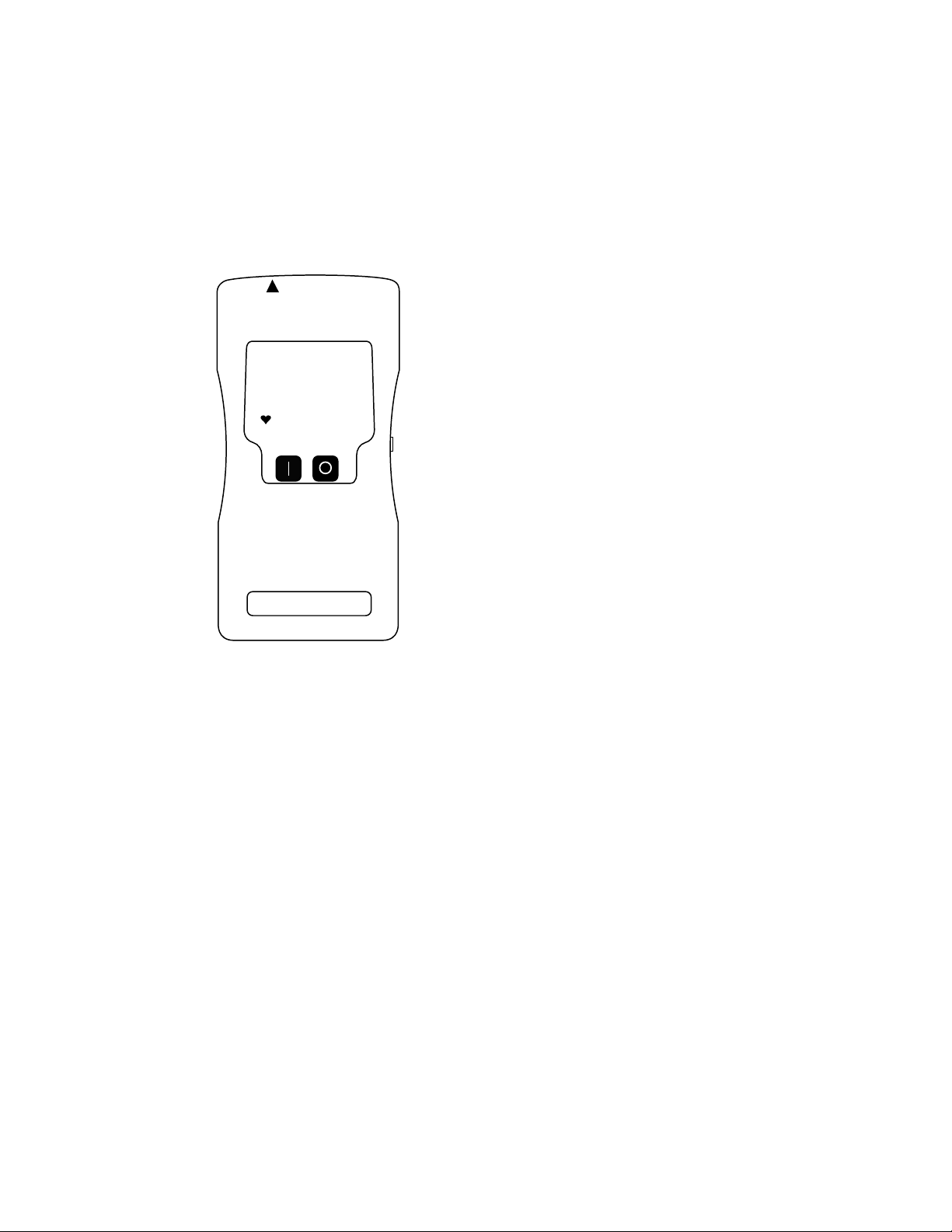
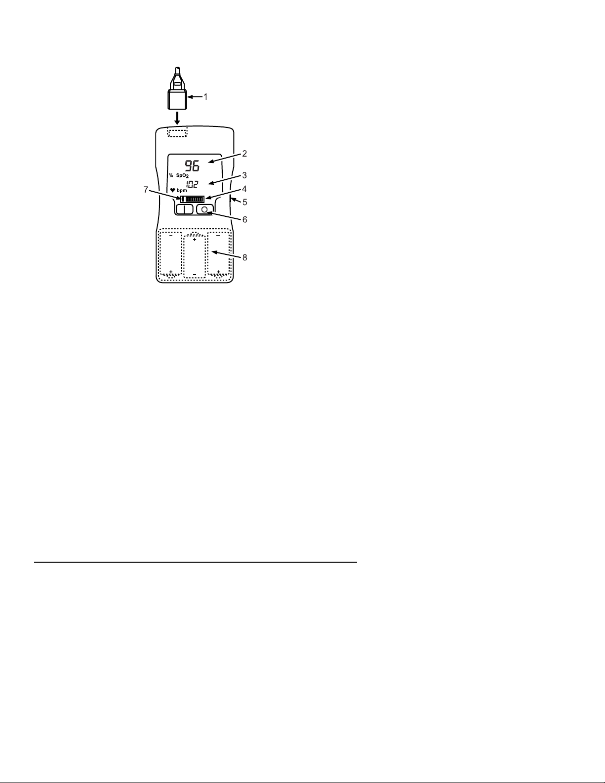
Description of Controls & Features
Figure 2-1: Oximeter Controls.
1. PATIENT CABLE/SENSOR
The sensor connects here. If you need the extra length of the patient cable,
attach the sensor to the patient cable, then attach the patient cable to the
oximeter’s PATIENT CABLE/SENSOR connector.
2. % SpO
The % SpO
calculate the SpO
DISPLAY
2
value is shown here. Dashes ( -- ) indicate the oximeter is unable to
2
value.
2
3. PULSE RATE DISPLAY
The pulse rate value is shown in beats per minute (BPM). Dashes ( --- ) indicate
the oximeter is unable to calculate the pulse rate value. Flashing
255 indicates
the pulse rate value is greater than 255.
2-2 Operation/Service Manual

Chapter 2: Oximeter Features
4. PULSE STRENGTH BARGRAPH
The eight-segment bargraph “sweeps” with the patient’s pulse beat, indicating
pulse strength. The bargraph is logarithmically scaled to indicate a wide range
of pulse strengths.
5. PRINTER OUTPUT
An optional printer connects here for printing data logs and spot check data. See
Printer for more information on the printer output.
6. R & Q KEYS
Press “R” to turn on the oximeter. Press “Q” to turn off the oximeter.
While the oximeter is on, momentarily pressing the “R” key increments the
patient number. While the oximeter is on, pressing and holding the “R” key for
about six seconds clears all the spot check data and resets the patient number to
P1.
The oximeter turns off automatically two minutes after the sensor is removed
from the patient or after the sensor is disconnected from the oximeter. This
feature extends the battery use time.
7. LOW BATTERY INDICATOR
When about two hours of battery use time remains, the left-most bargraph
segment lights. The oximeter will continue to operate normally until the
batteries no longer have sufficient power to operate the oximeter. At that point,
the oximeter automatically turns off.
8. BATTERIES AND ACCESS DOOR
The oximeter’s three “C” cell batteries are accessed through this door on the
back side of the oximeter. See Installing or Replacing the Batteries for details
on installing or replacing the batteries.
Operation/Service Manual 2-3


Chapter 3: Theory of Operation
Chapter 3: Theory of Operation
The oximeter determines SpO2 and pulse rate by passing two wavelengths of
light, one red and one infrared, through body tissue to a photodetector. During
measurement, the signal strength resulting from each light source depends on
the color and thickness of the body tissue, the sensor placement, the intensity of
the light sources, and the absorption of the arterial and venous blood (including
the time varying effects of the pulse) in the body tissues.
1. Low intensity red and infrared LED light sources
2. Detector
The oximeter processes these signals, separating the time invariant parameters
(tissue thickness, skin color, light intensity, and venous blood) from the time
variant parameters (arterial volume and SpO
calculate oxygen saturation. Oxygen saturation calculations can be performed
because oxygen saturated blood predictably absorbs less red light than oxygen
depleted blood.
) to identify the pulse rate and
2
Operation/Service Manual 3-1


Chapter 4: Using the Oximeter
Chapter 4: Using the Oximeter
Unpack the Oximeter
Carefully remove the oximeter and its accessories from the shipping carton.
Save the packing materials in case the oximeter must be shipped or stored.
Compare the packing list with the supplies and equipment you received to make
sure you have everything you’ll need.
Install the Batteries
The oximeter uses three standard “C” cell batteries (type LR 14). You can use
disposable alkaline batteries or rechargeable (type KR27/50) batteries.
If you use disposable batteries, be sure to dispose of them in compliance with
your institution’s guidelines and local ordinances.
If you use rechargeable batteries, it’s best to have two sets of batteries on hand.
That way, you can use one set of batteries in the oximeter while the other set of
batteries is recharging.
NOTE: If you’ve collected spot check data for printing, make sure you print the
spot check data before removing and replacing the oximeter’s batteries.
Removing the batteries erases spot check data from the oximeter’s memory.
Operation/Service Manual 4-1
Chapter 4: Using the Oximeter
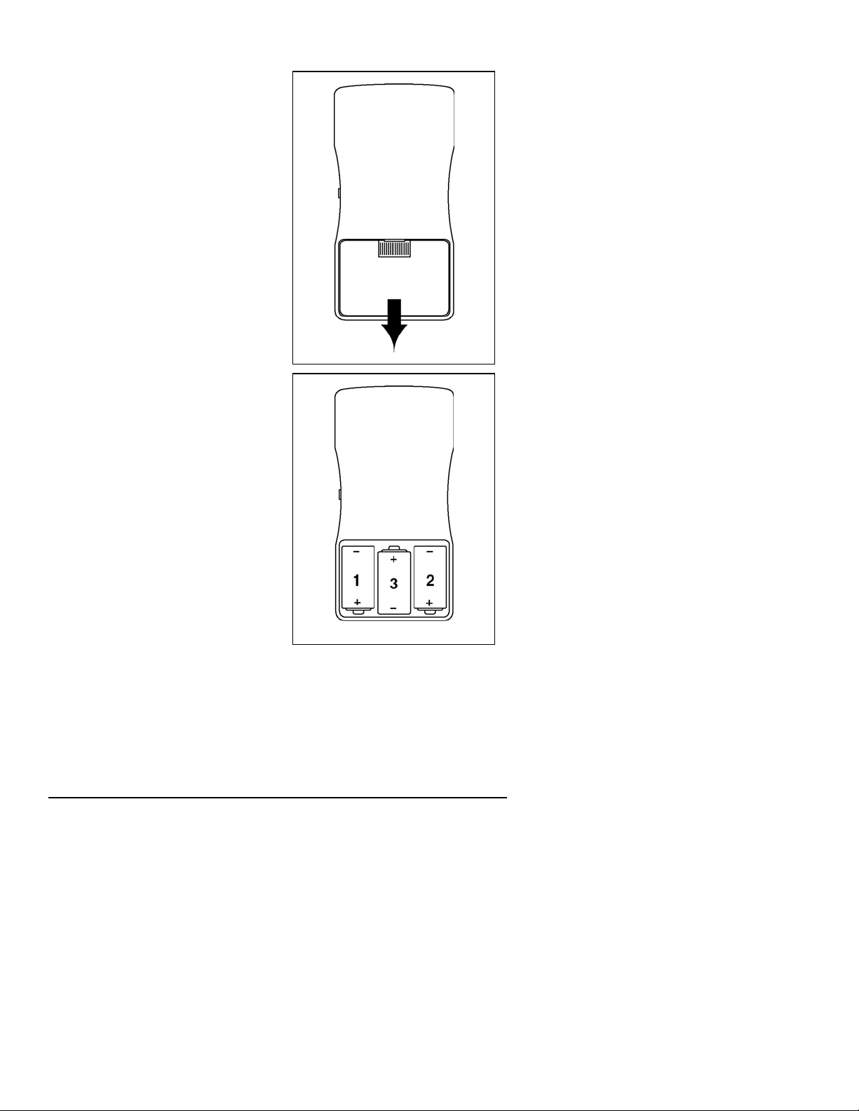
Installing or Replacing the Batteries
1. Turn over the oximeter so its back
is facing you.
2. Push on the thumb grip and slide
the door open.
3. If you're replacing the batteries,
remove the old batteries from the
battery compartment.
If the old batteries are disposable,
be sure to dispose of them in
compliance with your institution’s
guidelines and local ordinances.
If the old batteries are rechargeable,
be sure to charge them right away
so they'll be ready to use again as
soon as possible.
4. Install three batteries in the
Figure 4-1: Opening the Battery Door.
oximeter battery compartment.
Make sure the batteries are
installed in the proper direction.
NOTE: It is easiest to install the
batteries in the sequence shown in
Figure 4.2.
5. Slide the battery door closed,
pushing firmly until it snaps into
place.
Figure 4-2: Installing the Batteries.
4-2 Operation/Service Manual
 Loading...