

Page 1
Instruction Manual
90CA Microphone Calibration System
LI0056 – 13 May 2019
Page 2
Revision History
Any feedback or questions about this document are welcome at [email protected].
Revision Date Description
1 15 October 2009 First publication of this document
2 01 March 2012 Redesign of the manual. Added information about
calibration in general, calibration of microphone sets,
and preamplifiers. New diagrams and drawings about
hardware assembly and electrical connections
3 10 February 2017 File locations on page 64 corrected, new microphone
definition file.
4 13 May 2019 Adapter Cable with Optical Isolation added.
Warning about uninstalling LabView.
Copyright Notice
© 2012-19 G.R.A.S. Sound & Vibration A/S
http://www.gras.dk
Any technical documentation that is made available by G.R.A.S. is the copyrighted work of
G.R.A.S. and is owned by G.R.A.S.
The content in this document is subject to change without notice. G.R.A.S. Sound & Vibration A/S
is not liable or responsible for any errors or inaccuracies that may appear in this document.
Trademarks
Any product names mentioned in this document may be trademarks or registered trademarks of
their respective companies and are hereby acknowledged.
2
Page 3

Contents
Introduction .................................................................................. 5
Using This Manual ..................................................................................... 5
Introduction to Calibration ............................................................... 6
What is Acoustic Calibration? ...................................................................... 6
Which type of calibration do I need? ............................................................ 7
How often should I calibrate? ...................................................................... 8
The Concept of the 90CA Microphone Calibration System ..................... 9
Applications ............................................................................................ 10
The Basic Principles of 90CA: Microphone Calibration in Four Easy Steps ....... 11
Functional Block Diagram ......................................................................... 12
Hardware and Software for Level Calibration ............................................... 13
Hardware and Software for Frequency Calibration ........................................ 14
Delivered Components .................................................................. 16
Assembling and Connecting the Hardware ........................................ 17
Workspace for the Assembly ...................................................................... 17
PXI: Connections for Test of Microphones (Ext. Pol. and Prepol.) .................... 19
PXI: Connections for Test of Externally Polarized Microphone Sets ................. 21
PXI: Connections for Test of Prepolarized Microphone Sets ........................... 23
PCI: Connections for Test of Microphones (Ext. Pol. and Prepol.) .................... 25
PCI: Connections for Test of Externally Polarized Microphone Sets ................. 27
PCI: Connections for Test of Prepolarized Microphone Sets ........................... 29
Assembling the 90CA .............................................................................. 30
Settings for the Instruments included in the System ..................................... 32
Precautions for certain Types of Microphones .............................................. 32
Powering on the 90CA ............................................................................. 32
Mounting the Microphones ........................................................................ 33
System Verification...................................................................... 37
Initial verification of the system setup ......................................................... 37
Day-to-day Verification ............................................................................. 37
Introducing the Calibration Software SW0002 .................................. 38
3
Page 4

Calibrating Microphones and Microphone Sets ................................... 39
Starting the System ................................................................................. 39
Step 1: Registering the Microphone ........................................................... 41
Step 2: Performing a Level Calibration........................................................ 42
Step 3: Performing a Frequency Response Calibration .................................. 45
Step 4: Storing Calibration Results ............................................................ 46
Calibrating a Preamplifier ............................................................. 47
Step 1: Registering Test Conditions ............................................................ 48
Step 2: Frequency Response ..................................................................... 51
Step 3: LEMO Reference Level Test ........................................................... 52
Step 4: Storing Calibration Results ............................................................. 53
High Frequency Calibration ............................................................ 54
Working with the System Files and Documentation ............................ 56
Viewing and Editing the Microphone and Preamplifier Definition Files ............ 56
Setup.txt: The Microphone Calibration System Setup File ............................. 59
Editing the Calibration Charts in DIAdem .................................................... 62
The File Structure on the System Controller ................................................ 64
Warranty and Maintenance ............................................................ 66
Warranty ................................................................................................. 66
Calibration ............................................................................................... 66
Cleaning ................................................................................................. 66
Service and Repairs .................................................................................. 67
4
Page 5

Introduction
The G.R.A.S. 90CA Microphone Calibration System provides you with a computercontrolled level and frequency-response calibration of measurement microphones and
microphone sets. This highly automated process is convenient, yet reliable, with its
ready-to-use software and hardware, and auto-generated customizable documentation.
Additional software can be purchased for the calibration of preamplifiers.
Calibration with the 90CA is in compliance with
• A NSI S1.10 – 1966 (R1976)
• IEC Norm 61094-1
• IEC 61094-6
The 90CA provides accurate calibration hardware, easily changeable test conditions and
a highly reproducible calibration method
Using This Manual
Inside this manual, you will find
A description of the principles of the 90CA calibration system, with an overview of the
hardware and software for the different types of calibration in “” on page 8.
Diagrams and instructions for assembling and connecting the hardware for both the
PXI and the PCI version of 90CA “Assembling and Connecting the Hardware” on page
17.
Illustrations of which components of the 90CA to use for the different types of calibration for the different sizes of microphones: ”Mounting the Microphones” on page 33.
A description of the special calibration software included with 90CA and where and how
you can customize it: ”Introducing the Calibration Software SW0002” on page 38.
Detailed calibration procedures for “In general, the indicators are green when the
measurement is within the preset limits and red when the the measurement is outside
the limits.” on page 39, and for G.R.A.S. preamplifiers in ”Calibrating a Preamplifier”
on page 47 (if you purchased the preamplifier calibration option), and for ”High
Frequency Calibration” on page 54.
Descriptions of the data files included with 90CA and how to modify them in “Working
with the System Files and Documentation” on page 56.
Additional information about the warranty, cleaning instructions, and service and repairs
are also provided on page 66.
5
Page 6

Introduction to Calibration
For making documented, traceable, and approved measurements, your measurement
equipment must be calibrated.
Basically, calibration is a method that establishes the relationship between a measuring
device and its measurement units. This is done by comparing a device or the output of
an instrument to a standard with known characteristics. As an example, a ruler can be
calibrated by comparing it to a known standard. A meter is defined as the length of the
path travelled by light in vacuum in 1⁄299,792,458th of a second. When the relationship between the ruler and this standard is established, the ruler is calibrated and can be
trusted to provide reliable measurements.
This section introduces the most commonly used terms in relation to acoustic calibration.
What is Acoustic Calibration?
Calibration means the comparison of the value indicated by a measuring instrument with
a nominal value that is provided by a given standard.
The equipment used for the calibration must itself be suitably calibrated to ensure an
unbroken trace back to the standard kept at a national or international institute.
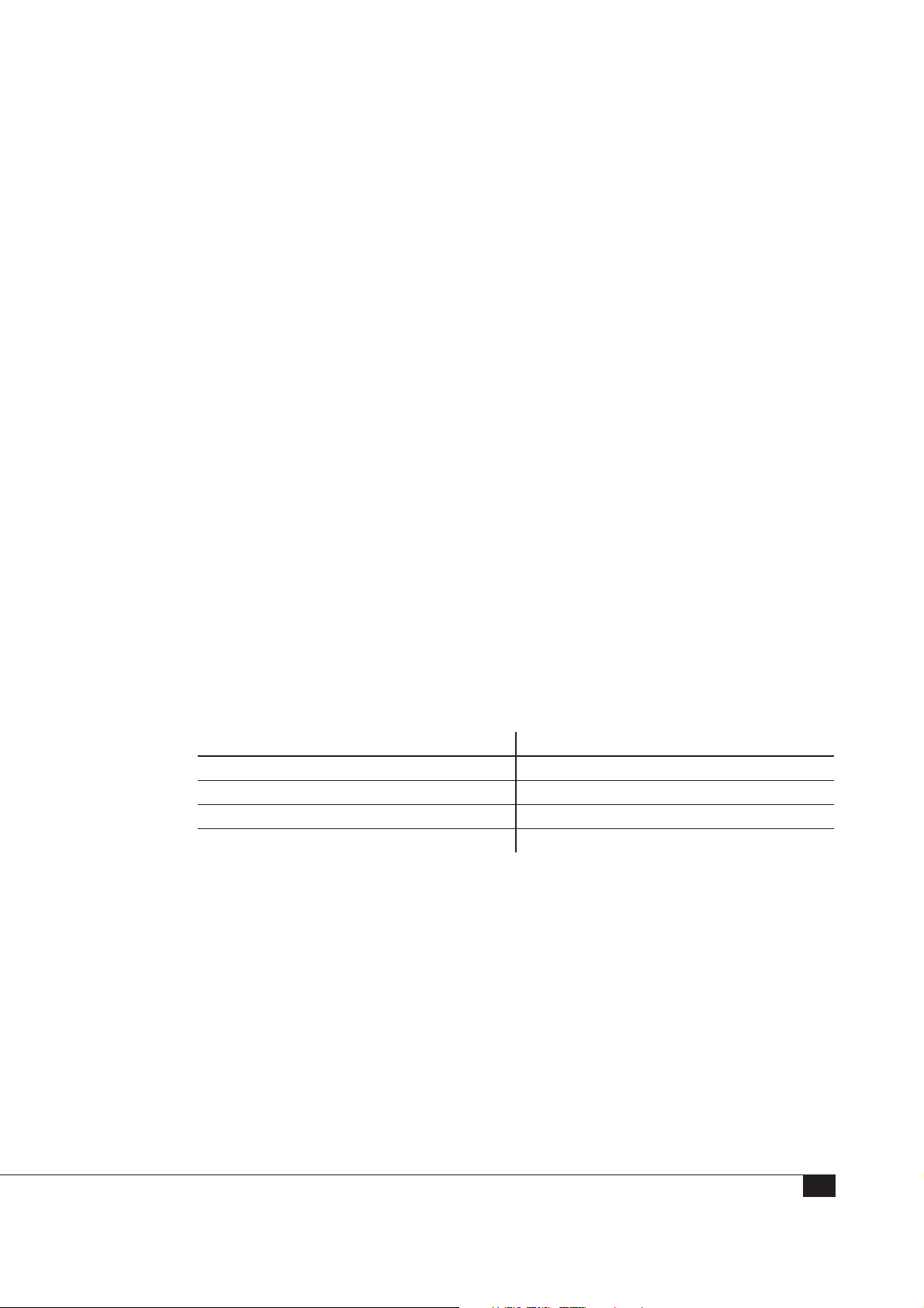
The Calibration Pyramid
National / International Standard
Reference Standard
Working Standard
Measuring Instrument
Fig. 1. The calibration pyramid
The calibration pyramid is a hierarchy of comparisons of the standards used to calibrate
measurement instruments, ranging from the least accurate standard (many working
standards) at the bottom of the pyramid to the most accurate standard at the top.
Secondary
Calibration
Accredited Calibration
Traceable Calibration
6
Page 7
Traceable Calibration
An instrument has a traceable calibration if the measurement instrument used for
performing the calibration is traceable to national or international institutes / standards
through an unbroken chain of comparisons all having stated uncertainties.
Accredited Calibration
An instrument has an accredited calibration if the calibration is performed by an
approved accredited calibration laboratory. Approval for accredited calibration is granted
by a national metrology institute after careful evaluation and inspection of the laboratory
in question.
Secondary Calibration
The secondary calibration has the next highest metrological quality in an area. The calibration value is assigned by comparison with a primary standard of the same quantity.
Primary Standard
The primary calibration (reference standard) has the highest metrological quality available at a given location or in a given organization. Its value is accepted without reference
to other standards of the same quantity.
In many countries, a body has been established to maintain primary standards of
measurements that will be used to provide traceability to customers’ instruments. The
national metrology institute supports the metrological infrastructure in that country by
establishing an unbroken chain from the top level of standards to an instrument used for
measurement.
National Metrology Institute Country
DANAK Denmark
PTB Germany
NPL UK
NIST USA
Fig. 2. Examples of national metrology institutes
Which type of Calibration do I need?
For performing a quality measurement, you must keep these factors in mind:
1. Resolution: Does the measurement meet the requirements of the application?
2. Accuracy: Does the measurement reflect the true characteristics of what is
measured?
3. Precision: Do you get the same result each time you measure the same quantity?
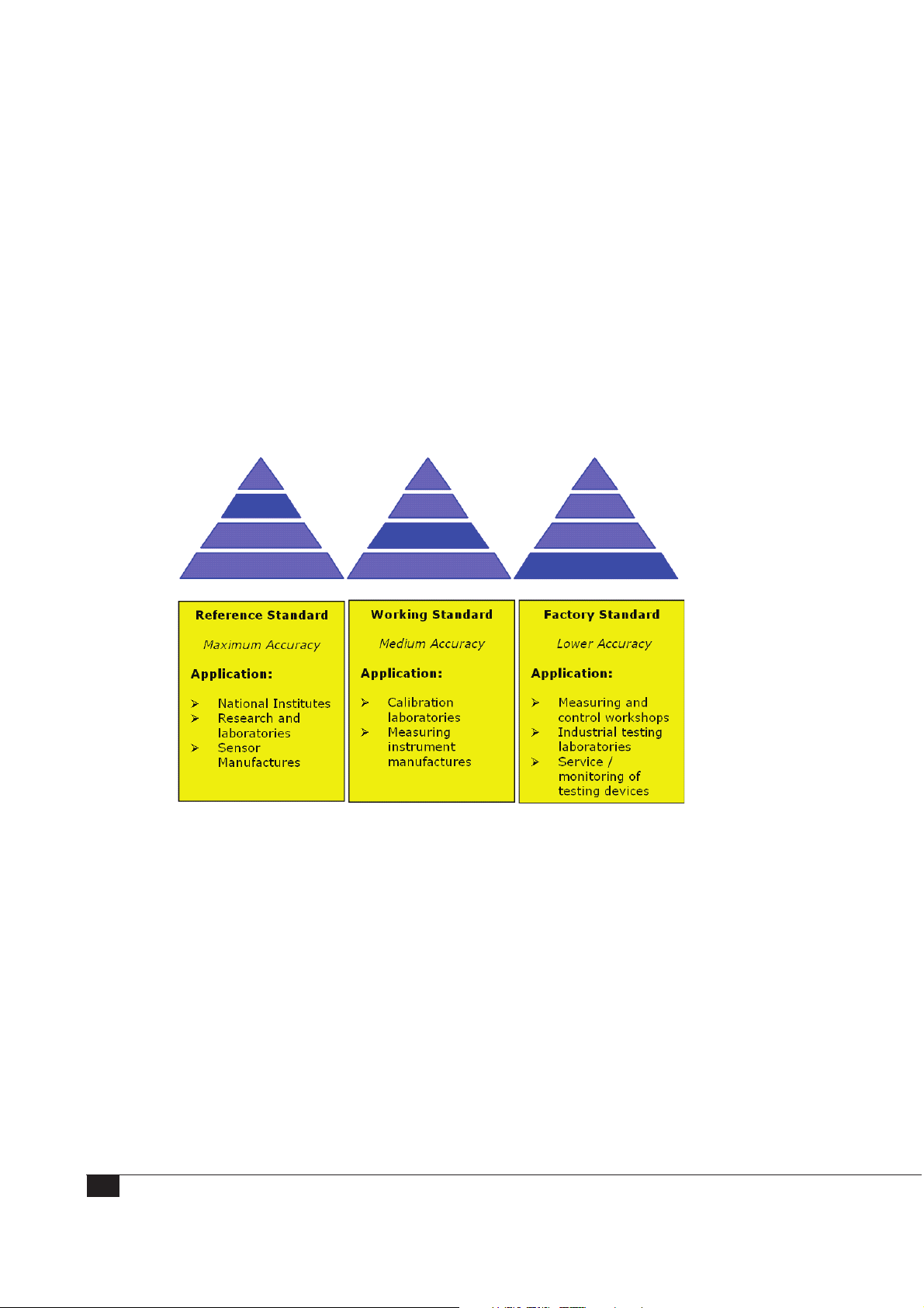
The accuracy of the calibration needed is directly dependent on these considerations.
7
Page 8
How often should I calibrate?
How often you should calibrate your equipment depends on the type of measurements
as well as on your quality assurance system. Use the following guidelines to determine
when calibration is needed:
• When you receive a new instrument
• When a specified time period has elapsed (often one year)
• When a specified period of usage (operating hours) has elapsed
• When an instrument has been subjected to shock or vibration that may have
affected its performance
• Whenever measurement results appear to be questionable
Fig. 3. Accuracy of Calibration
8
Page 9
The Concept of the 90CA Microphone Calibration System
The G.R.A.S. Microphone Calibration System 90CA provides you with a convenient,
yet reliable and automated level and frequency response calibration of measurement
microphones and microphone sets. The 90CA calibrates in compliance with
• ANSI S1.10 – 1966 (R1976)
• IEC Norm 61094-1
• IEC 61094-6
An optional module for calibration of preamplifiers is available.
The 90CA is delivered with ready-to-use software and hardware, as well as preinstalled
test parameters for G.R.A.S. microphones and preamplifiers. The 90CA is available in
two versions: a PXI-based version with boards for mounting in a NI PXI Express chassis
and a PCI-based version with boards for use in a PC. Functionality and specifications are
identical for the two. See Packing List and Electrical Connections for further information.
Main Features
• A highly automated and computer-controlled calibration process
• Accurate calibration hardware
• Ready-to-use software and hardware
• Preinstalled test parameters for G.R.A.S. microphones and microphone sets
• Optional software for test of preamplifiers
• Test conditions easily changeable
• Highly reproducible calibration method
• Auto-generated, customizable documentation for printing
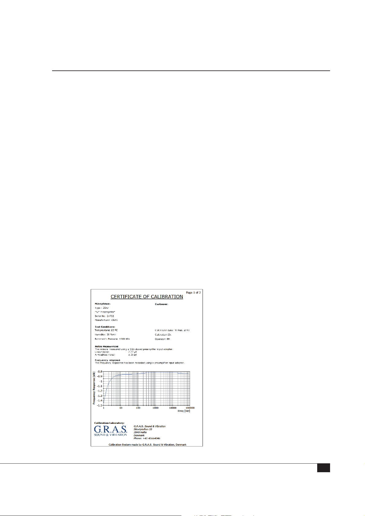
Fig. 4. Example of a calibration certificate
9
Page 10

Applications
You can use the 90CA Microphone Calibration System for all types of IEC-standardized
1
⁄8“, ¼” , ½”, and 1” measurement microphones to perform.
• Level calibration of microphones using a pistonphone and the insert voltage
• Frequency calibration of microphones using an electrostatic actuator
• Calibration of externally polarized microphone sets
• Calibration of prepolarized microphone sets
• Calibration of preamplifiers
• Calibration up to 92 kHz
technique
Note: For microphones with a non-removable protection grid, frequency calibration is not feasible. For G.R.A.S.’ free-field microphones, the system automatically compensates for the free-field correction. For non-G.R.A.S free-field microphones, the free-field correction values can be entered manually.
Note: The high-frequency calibration above 92 kHz requires a 33210A or
33220A Signal Generator and a 34410A Digital Multimeter.
These applications are described in this manual.
Traceability and Accrediting
The system has been tested by G.R.A.S. Sound & Vibration and is delivered with a test
certificate for the complete system, specific instruments and their serial numbers listed.
The microphones and the pistonphone 42AP that is included are reference traceable to
national standards established at National Physical Laboratory (NPL) in Great Britain.
For daily reference instruments check, use the Reference Microphone 40AG that is
included.
Accreditation for the 90CA Reference Units
An accredited calibration of the 42AP Pistonphone, the 40AG reference microphone,
and the 26AG Insert-Voltage Preamplifier is available from G.R.A.S. Order OP0022
Accredited Calibration of Reference Units.
10
Page 11
The Basic Principles of 90CA: Microphone Calibration in Four Easy Steps
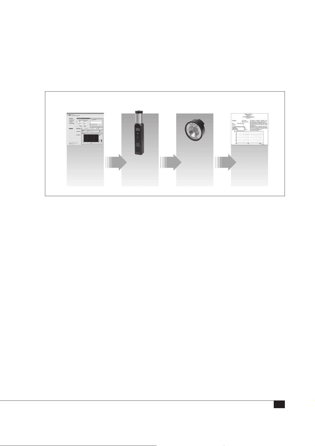
The 90CA Microphone Calibration System was designed to eliminate the risk of operator
errors during calibration. The workflow is simple and straight-forward with its four steps as
shown in the following figure.
Microphone
Registration
Fig. 5. The four steps of calibration with the 90CA
Level
Calibration
Microphone Registration is the first step. You enter the test conditions (meteorological
data) and microphone parameters (sensitivity, frequency response, tolerances, etc.) into
the system. The system has a database that already contains calibration information
for G.R.A.S. microphones (sensitivity, frequency response, tolerances, and so on). This
database can easily be extended to contain the same type of details about microphones
from other manufacturers.
Level Calibration uses the pistonphone and an insert-voltage preamplifier to determine
the open-circuit sensitivity of the microphone capsule at 250 Hz @114 dB.
Frequency Calibration is performed after the level calibration to determine the frequency response using an electrostatic actuator.
The Calibration Certificate is a file that contains all the results for the level and the
frequency calibration. The layout, data used, text, and logo for the certificate can be
customized. The file can be saved as a PDF file.
Frequency
Calibration
Calibration
Certifi cate
Ambient Conditions for the Calibration
Ambient noise: < 65 dB
Temperature: 20 - 25° C
Relative Humidity: 30 – 70 %
11
Page 12
Functional Block Diagram
Microphone Registration
Level Calibration
Microphone
Sound
Source
Level Calibration Equipment + Microphone
Frequency Calibration
Actuator
Frequency
Stepping, e.g. 1/6oct.
Frequency Calibration
Microphone
Equipment + Microphone
Preamplifier 1
Preamplifier 2
Off
Auto-switching
DC
Power Supply
Power, Signal Conditioning, and Switching
Microphone
Definition File:
- Test Conditions
- Test Details
- Preset test
parameters
PCI
Cards
Microphone
Calibration File:
- Open-circuit
Sensitivity
@ 250 Hz
- Frequency
Response
Calibration
Software
Sensitivity @ 250 Hz
System Controller
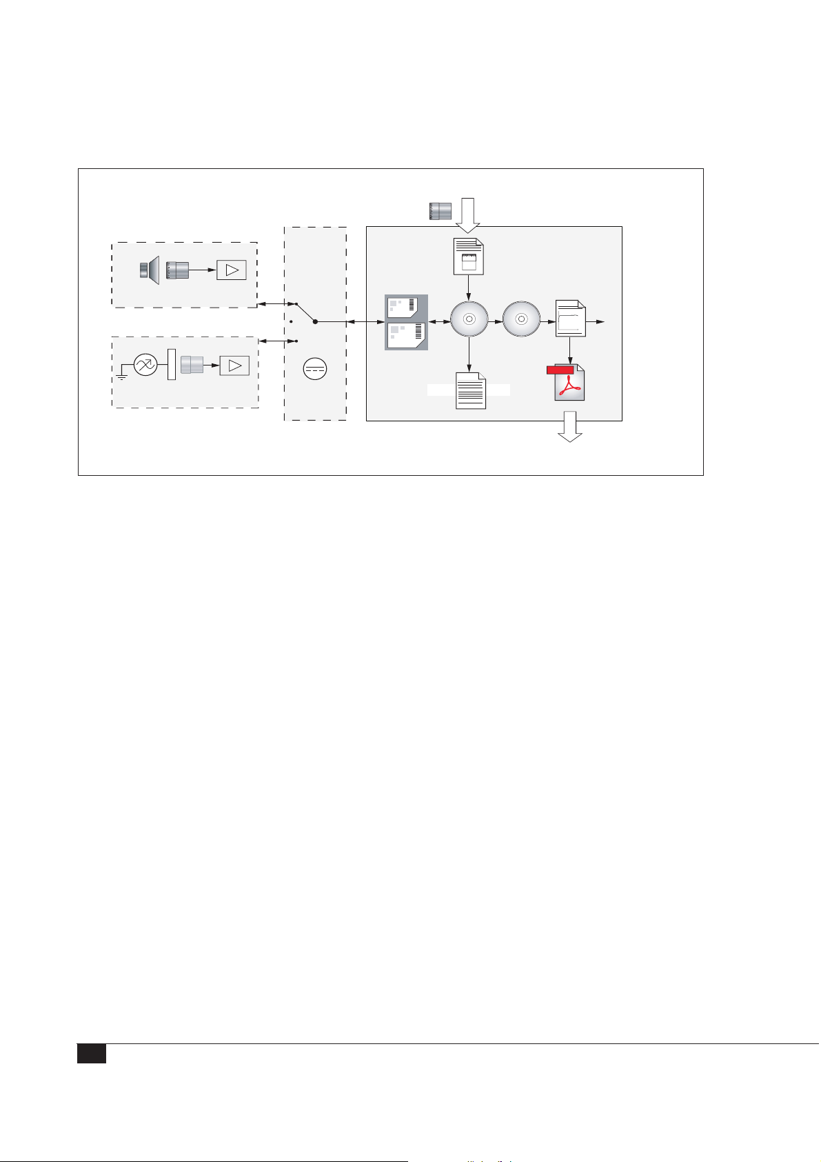
Fig. 6. The complete microphone calibration system represented by functional blocks
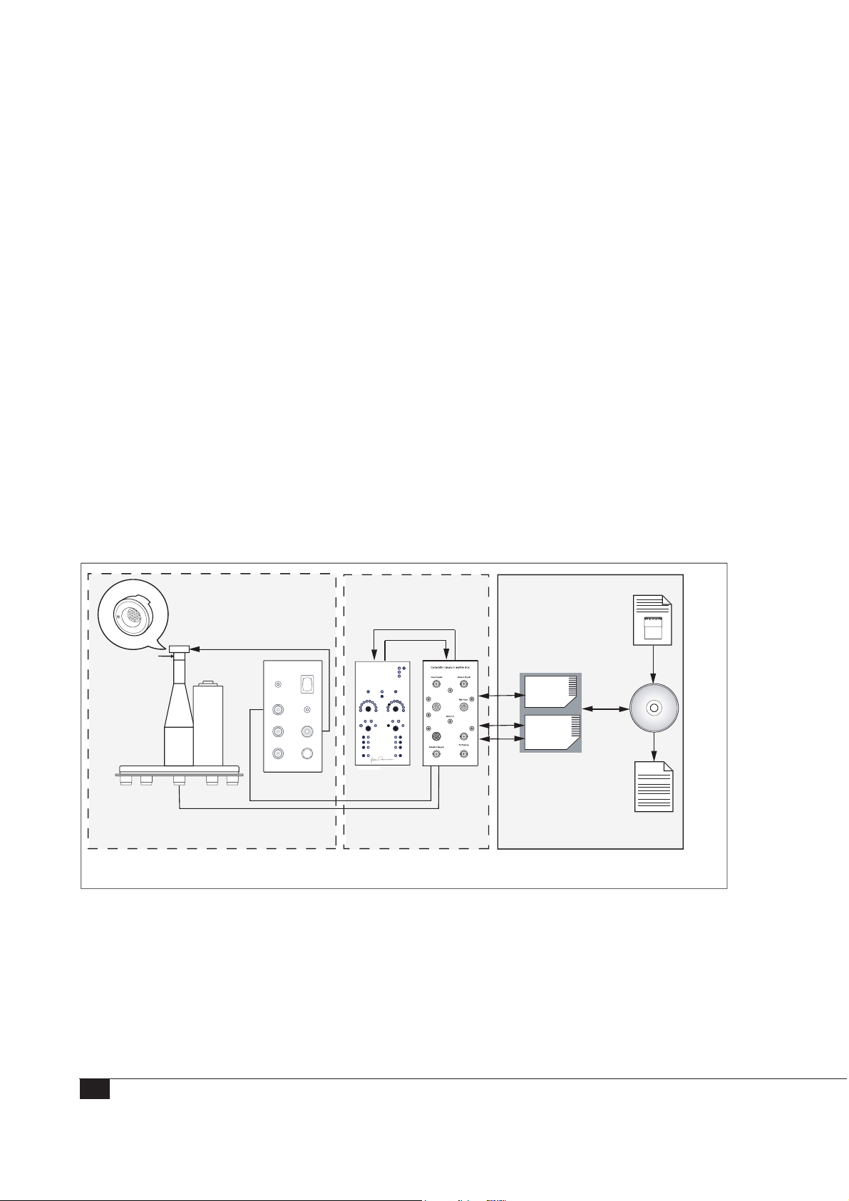
A overall functional block diagram of the 90CA has four areas as explained here.
The Level Calibration Equipment block covers the components needed to determine
the microphone’s open-circuit sensitivity [mV/Pa].
Calibration
Certicate
Print
PDF
PDF Doc.
Hz
Adobe
Documentation
Software
Calibration Certificate
The Frequency Calibration Equipment block covers the components needed to determine the microphone’s frequency response.
The Power, Signal Conditioning, and Switching block covers the DC power supply,
signal conditioning, and automatic switching between level and frequency calibration.
The System Controller block covers the following:
• PXI cards for digital I/O and data acquisition with PXI-based system control or
equivalent PCI-cards for PCI-based system control
• Preinstalled calibration software (SW0002) specifically designed for the 90CA
• Preinstalled microphone and preamplifier definition files (described elsewhere in
this manual)
• Microphone Calibration File for the test results
• Software for generating the documentation - the calibration certificate
12
Page 13
Hardware and Software for Level Calibration
Pistonphone Auto-ON/OFF
Static air pressure
Spring arrangement
Preamplifier
Type 26AG
Microphone
to be calibrated
Pistonphone
Type 42AP
Pistonphone Calibration Stand
G.R.A.S.
Pistonphone
AL0017
G.R.A.S.
PowerModule
Type12AQ Remote
Channel1
Overload
Latch
GainindB
20
30
40
10
50
50
0
0
60
60
-10
-10
-20
-20
70
Filter
HP
AW
Lin
Lin
Ext
CCPInput
FloatingOutput
Polarization0V
Preamp.±15V
SignatureSeries
Power Module
Type 12AQ
Power
Battery
Channel2
Overload
GainindB
20
30
40
10
50
60
70
Filter
HP AW
Ext
SysCheck
G.R.A.S.
RA0192
Extended
Frequency
Range
Preamp.
Pistonphone
Insert
Active
Polarization
Preamp. Preamp.
Actuator
Stand
Control Box
RA0192
Preamp.
Test
Input
InputAdapter
PXI
Cards
Control
Card
Data Aquisition Card
Microphone
Definition File
Level Calibration:
- Pistonphone level
and frequency
- Test specifications
(open-circuit sensi tivity [max;min])
Calibration
Software
SW0002
Microphone
Calibration File
Output for
Level Calibration:
Open-circuit
Sensitivity
- Level [mV/Pa]
- Pass/Fail indication
tnempiuqEnoitarbilaCleveL
Signal Conditioning,
Power, and Switching
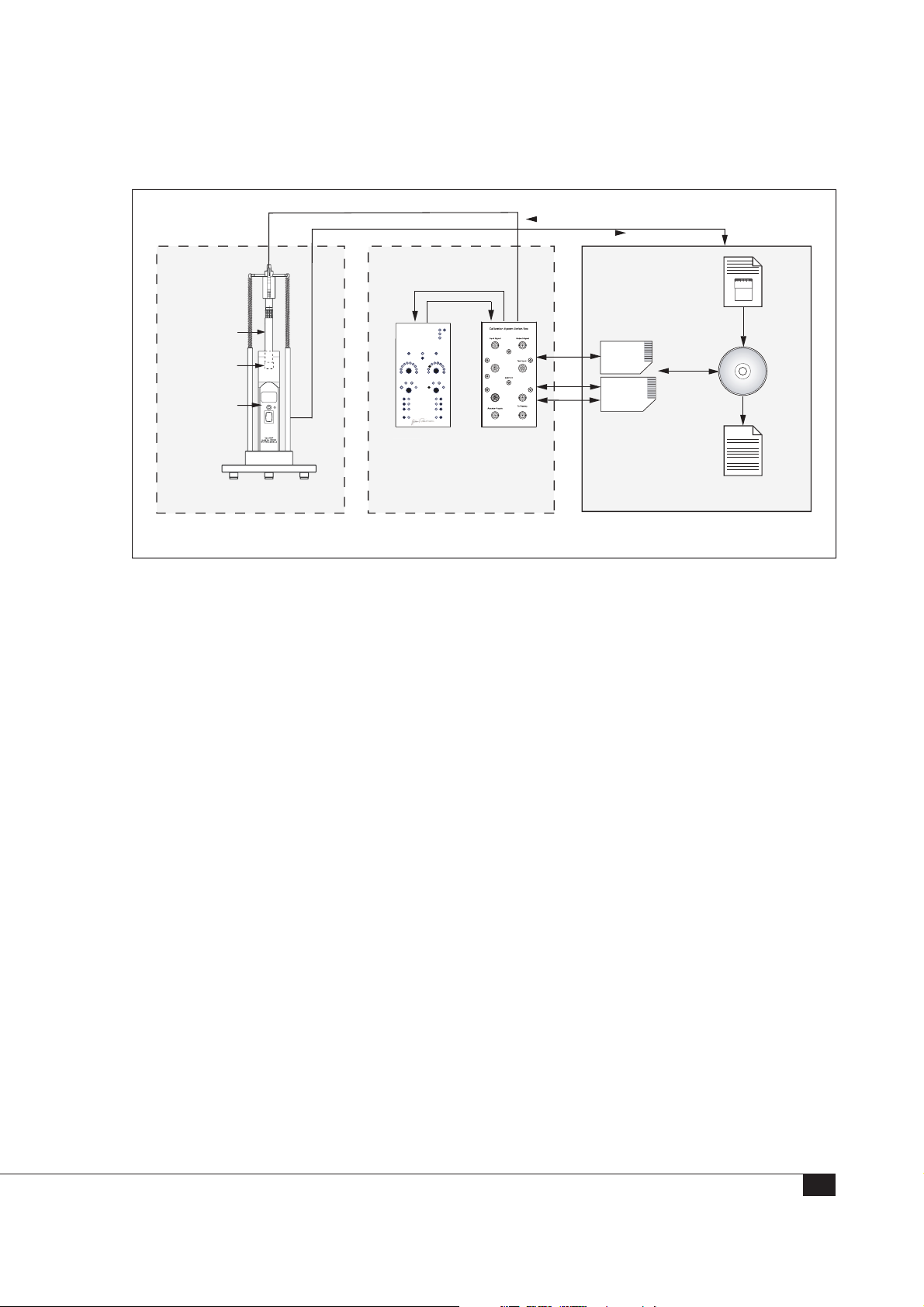
Fig. 7. Functional block diagram of the 90CA hardware and software for level calibration
The hardware and software for level calibrations are introduced here.
Level Calibration Equipment
• Pistonphone 42AP: A well-defined sound level reference (sound source); it is
automatically switched on/off via a COM port, and it automatically reads the
static air pressure.
• ½” Preamplifier 26AG (for ½” microphones) OR (not shown) ¼” Preamplifier
26AN (for ¼” microphones): Both types with an integrated 7-pin LEMO connector and configured for insert-voltage technique.
• Pistonphone Calibration Stand AL0017: A fixture for holding the preamplifier
securely in place in the pistonphone and ensuring a stable workspace.
Power, Signal Conditioning, and Switching
• Power Module 12AQ: A dual-channel power module with supply voltages
and signal conditioning for externally polarized and prepolarized preamplifiers/
condenser microphones.
rellortnoCmetsyS
• Control Box RA0192: Software-controlled switchbox that automatically
switches the signal path between level calibration and frequency calibration.
13
Page 14
System Controller
The system controller has PXI or PCI cards and software preinstalled.
• Control Card: National Instruments Digital I/O PXI-6509 (PCI 6503), Input/
Output Module (A/D Conversion); controls the signal switching between level and
frequency calibration.
• Data Acquisition Card: National Instruments Dynamic Signal Acquisition Board
PXI-4461 (PCI 4461) with 24-bit analog inputs and outputs and a sampling rate
of 204.8 kS/s.
• Microphone Calibration Software
• Microphone Definition File: For level calibration, this input file contains
- test parameters such as pistonphone level and frequency
- test specifications for the microphone (microphone sensitivity [max; min]).
• Microphone Calibration File: For level calibration, this output file contains:
- the microphone’s open-circuit sensitivity in [dB re. 1 V/Pa] and [mV/Pa]
- “Pass” / “Fail” indication
Hardware and Software for Frequency Calibration
PXI
Cards
Control
Control
Card
Card
NI6503
Data Acquisition Card
Microphone
Definition File
Frequency Response
- Test frequencies
(1/6 octave stepping)
- [Max;min] for each
test frequency
Microphone
Calibration File
Output for
Frequency Response:
- Level (magnitude [Pa]
and phase)
- Pass/Fail indication
.
R
A
.
.
S
G
.
R
A
Microphone
for calibration
Preamplifier
calibration
Calibration Stand
0
4
0
1
26AB
(inside
stand)
Actuator
AL0010
Adapter
Electrostatic Actuator
RA0014
¼”- ½” Adapter
G.R.A.S.
AF0008
Frequency Calibration Equipment
G.R.A.S.
Actuator Supply
Type 14AA
Power
On
AC Input
Max. 1Vrm s
Overload
AC Output
AC Output
+800VDC
AC Output
+200VDC
Actuator Supply
14AA
G.R.A.S.
Power
PowerModule
Battery
Type12AQ Remote
Channel1
Channel2
Overload
Overload
Latch
Gainin dB
GainindB
20
20
30
30
40
10
10
50
50
0
0
60
60
-10
-10
-20
-20
70
Filter
Filter
HP
HP AW
AW
Lin
Lin
Ext
CCPInput
GND
Preamp.±15V
FloatingOutput
Polarization0V
SignatureSeries
SysCheck
Power Module
G.R.A.S.
RA0192
Extended
Frequency
.
Range
Preamp.
Piston-
Preamp.
phone
40
50
60
Insert
Active
70
Polarization
Ext
Preamp. Preamp.
Test
Actuator
Input
Stand
InputAdapter
Control
Box
Signal Conditioning System Controller
Fig. 8. Functional block diagram of the 90CA hardware and software for frequency calibration
The block diagram for frequency calibration is similar to the diagram for level calibration.
The details are the same for the system controller and the power, signal conditioning,
and switching. The equipment block is different.
Calibration
Software
SW0002
14
Page 15

Frequency Calibration Equipment
• ¼” Preamplifier 26AB (¼” -to-½” adapter AF0008 supplied)
OR (not shown)
½” Preamplifier 26AK; both amplifiers with integrated 7-pin LEMO connector.
• ½” Electrostatic Actuator RA0014: for testing the frequency response of stan-
dard ½” and ¼” microphones; an adapter is included for testing ¼” microphones;
can be connected directly to the Actuator Supply 14AA.
• Actuator Calibration Stand AL0010: provides a convenient platform and has
a fixture for holding the preamplifier securely in place as well as recesses and
column for safely parking the electrostatic actuator RA0014 and microphone
protection grids when not in use.
• Microphone Set Calibration Stand AL0021: provides a platform and has a
fixture for holding a microphone set securely in place. (Not shown in Fig 8, shown
in the connection diagrams for microphone sets in “Assembling and Connecting
the Hardware”.)
• Actuator Amplifier 14AA: includes a 230 V AC power cable.
15
Page 16
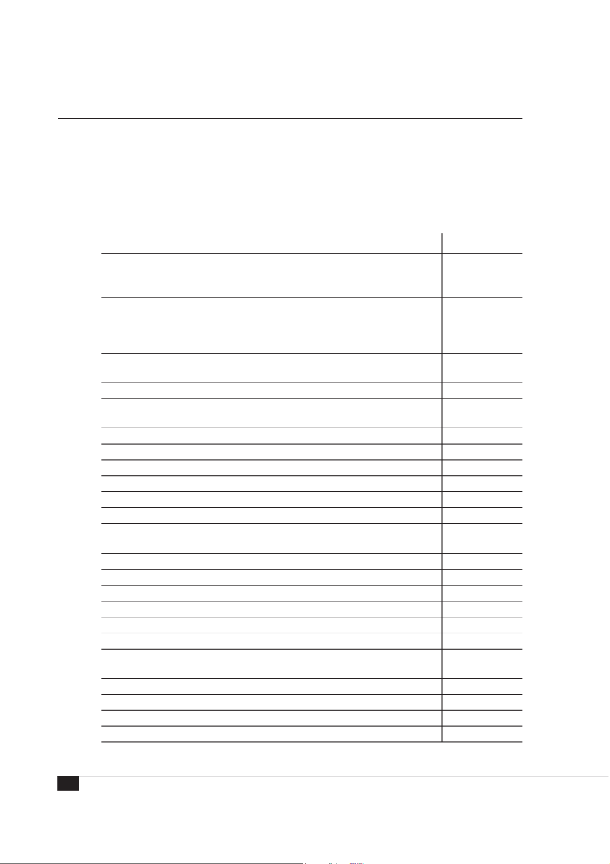
Delivered Components
The 90CA Microphone Calibration System includes all accessories for calibrating microphones from G.R.A.S.
Packing List for the 90CA
Please note that the included hardware from Natinal Instruments may be newer and
improved versions with different product designations than those listed here.
System Controller with preinstalled cards and software
PCI: System Controller, including:
NI Dynamic Signal Acquisition Board PCI-4461
National Instruments Digital I/O PCI-6503, or newer hardware version.
PXI: NI PXIe-8101 Embedded Controller, including:
National Instruments PXIe1071 4-Slot 3U PXI Express Chassis
NI Dynamic Signal Acquisition Board PXI-4461
National Instruments Digital I/O PXI-6509, or newer hardware versions.
National Instruments software Diadem version 10.2 (or later), Base
Discontinued
HW1003
SW0013
Edition
Calibration System Software for 90CA SW0002
National Instruments Sound and Vibration Analysis SW Run-Time
SW0012
License 779875-01
For Level Calibration
Pistonphone Calibration Stand AL0017
Intelligent Pistonphone, including RS-232 control cable 42AP
¼” LEMO Insert Voltage Preamplifier 26AN
½” LEMO Insert Voltage Preamplifier 26AG
For Frequency Calibration
¼” LEMO Preamplifier with Inline Barrel Adapter AF0008 for
26AB
¼”preamplifier and ½”microphone
½” LEMO preamplifier (for use with most non-G.R.A.S. microphones) 26AK
½” Electrostatic actuator (includes ¼” microphone adapter RA0017) RA0014
Actuator Calibration Stand AL0010
Microphone Set Calibration Stand AL0021
Electrostatic Actuator Amplifier, including 230 V AC power cable 14AA
For Power, Signal Conditioning, and Switching
2-Channel CCP/LEMO Power Module with Signal Conditioning and
12AQ
Computer Interface
Control box (no cables included in the box) RA0192
½” Pressure microphone for reference 40AG
Cables, Connectors, Adapters, and Tools
National Instruments Cable 180524-10 (50-position ribbon cable) AA2006
16
Page 17

1 m BNC cables (5) AA0033
3 m LEMO extension cable (3) AA0008
RS232-USB Adapter with optical isolation KE0138
BNC T-connector AC0021
Straight adapter for ½” microphone and ¼” preamplifier RA0003
microphone and ¼” preamplifier adapter RA0063
⅛
½” microphone tool RA0081
¼” microphone tool RA0200
microphone tool RA0210
⅛”
Documents
90CA Instruction manual LI0028
42AP, 12AQ, 14AA Instruction manuals
G.R.A.S. license for SW0002
Calibration documentation
Options
Preamplifier calibration module 0P0020
Accessories for calibration of 1” microphones 0P0021
Accredited calibration of 42AP Pistonphone, 40AG Reference
Microphone, 26AG Preamplifier and 26AK Reference Preapmlifier
OP0022
Assembling and Connecting the Hardware
Workspace for the Assembly
To prepare the assembly, make sure you have at least 1 square meter free space available. For easy day-to-day use, you need easy access to the Level Calibration Equipment
and the Frequency Calibration Equipment. The monitor, mouse, and keyboard should
be easy to reach. After they are connected, the System Controller, the RA0192 Switch
Box, and the 12AQ Power Module can be placed as far away from the other equipment
as the available cable lengths allow.
The following pages show how the components of the 90CA are connected for calibration of microphones—both externally polarized and prepolarized (CCP), externally
polarized microphone sets, and prepolarized microphone sets. The three setups are very
similar.
The main differences are
• The AL0010 Electrostatic Calibration Stand is used for calibration of microphones.
• The AL0021 Microphone Set Calibration Stand is used for calibration of microphone
sets.
• LEMO to LEMO cables are used for calibration of microphones and for externally
polarized microphone sets. BNC to BNC are used for prepolarized microphone sets.
17
Page 18
1
Digital I/O
NI PXI - 6509
1
NI PXI-e 1071 PXI Express Chassis with
Embedded Controller, Data Acquisition and I/O Cards
PXI- based System Control and Data Acquisition
12
2
AO0
AO1
4
NI PXI - 4461
24-bit 204.8 kS/s
35
AI1
AI0
To
Control
Signals
From
Signal
11 10
Excitation
5
4
(TEDS)
8
Test
8
7
DVI
6
NI PXIe 8101
Embedded Controller
RA0192 Switch Box12AQ Power Module14AA Actuator Supply
Range
Extended
Frequency
RA0192
G.R.A.S.
Preamp.
Input
Preamp.
Polarization
phone
Piston-
Insert
Active
InputAdapter
Stand
Preamp. Preamp.
Actuator
13
15
9
RS232 Adapter
Cable with
Optical Isolation
Control
Cable
9
10
11
RS232
G.R.A.S.
Pistonphone
calibration stand
42AP Pistonphone in
SysCheck
Channel 2 Channel 1
Output
CCPInput
Mic.Input
SerialNo. XXXXX
+
8-18VDC
Ext.Supply
Level Calibration Equipment
PXI: Electrical Connections for Calibration of Microphones (Ext. Pol. and Prepol.)
Actuator Stand
Electrostatic Actuator and
Frequency Calibration Equipment
18
Polarization and Supply Voltage Signal Switching
14
15
G.R.A.S.
Type xxxx
.
4
S
.
1
A
0
.
0
R
.
A
G
R
G.R.A.S.
Actuator Supply
14
Overload
Type14AA
On
Power
ACInput
Max.1Vrms
13 12
GND
+800VDC
ACOutput
+200VDC
ACOutput
ACOutput
Page 19

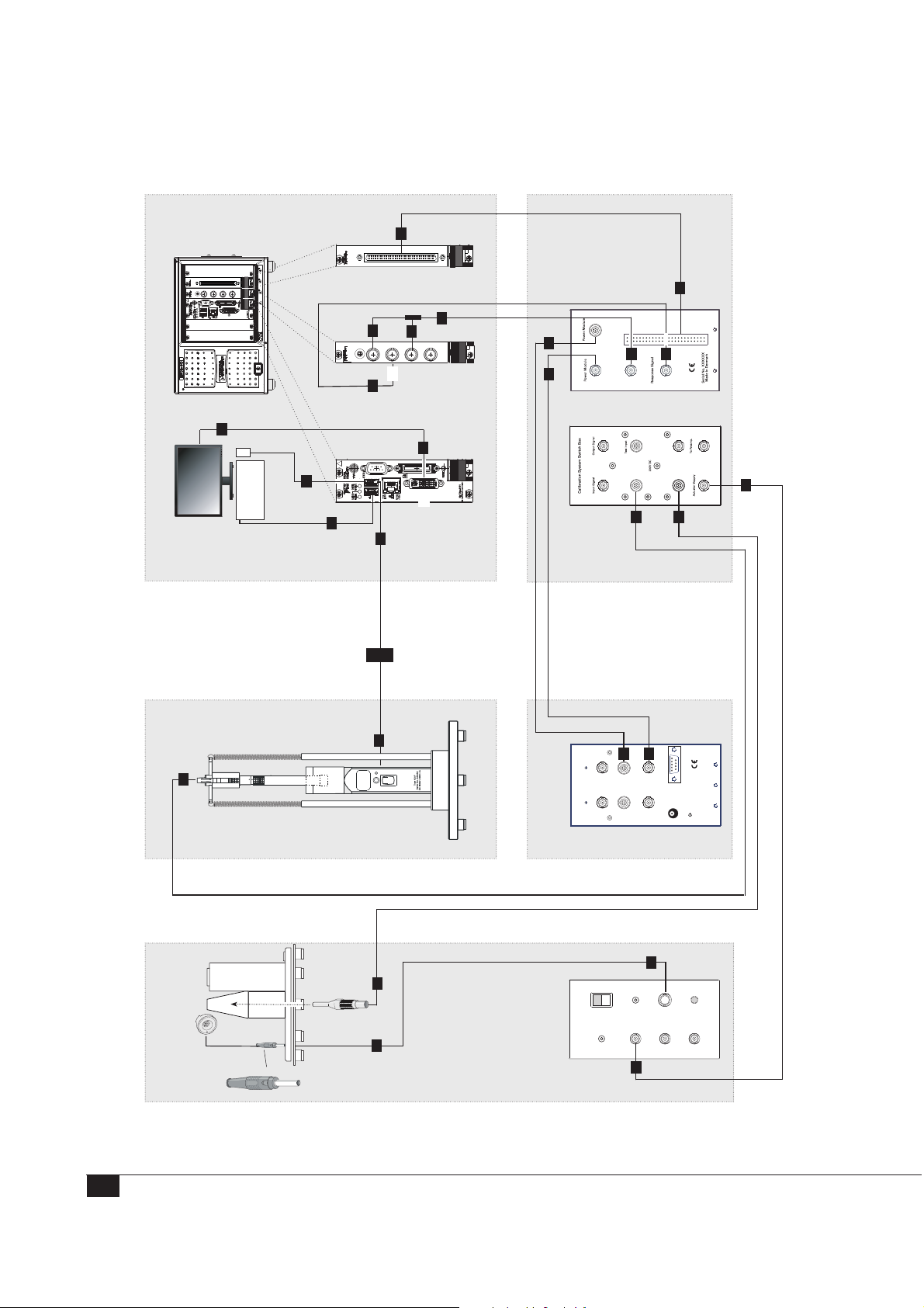
PXI: Connections for Test of Microphones (Ext. Pol. and Prepol.)
Important: All electrical devices must be switched off while you are setting up the
90CA.
1. Use the gray 50-position ribbon cable to connect the 6509 Digital I/O card to the
“Control Signal” socket on Switch Box RA0192 (socket on the rear).
2. Plug the BNC T-connector (two-way splitter) into the “AO 0” socket (output 0) on
the NI 4461 Dynamic Signal Acquisition Board.
3. Use a BNC cable to connect one branch of the BNC T-connector to “AI 0” socket
(input 0) on the NI 4461 Dynamic Signal Acquisition Board.
4. Use a BNC cable to connect the other branch of the BNC T-connector to the
“Excitation Signal” socket on the RA0192 Switch Box (socket on the rear).
5. Use a BNC cable to connect the “AI 1” input socket on the NI 4461 Dynamic
Signal Acquisition Board to the “Response Signal” BNC connector on the RA0192
Switch Box (socket on the rear).
6. Connect the keyboard to one of the USB slots on the PXIe 8101 Embedded
Controller.
7. Connect the mouse to the other USB slot on the PXIe 8101 Embedded Controller.
8. Connect the monitor to the DVI socket on the PXIe 8101 Embedded Controller
9. Use the control cable for the 42AP to connect it to the COM port of the Adapter
Cable with Optical Isolation and then connect this cable to a USB port of the PXI
Embedded Controller. (The PXI controller has one more USB slot than shown in the
connection diagram.)
10. Use a LEMO-to-LEMO cable to connect the “To Power Module” LEMO-socket
on the rear of the RA0192 to the Channel 1 LEMO “Input” on the 12AQ Power
Module.
11. Use a BNC cable to connect the “From Power Module” BNC-socket on the rear of
the RA0192 to the Channel 1 BNC “Output” on the 12AQ Power Module.
12. Use a LEMO-to-LEMO cable (AA0008) to connect the “Preamp Pistonphone”
connector on the RA0192 to the (insert voltage) preamplifier to be mounted in the
pistonphone stand.
13. Use a BNC cable to connect the “Actuator Supply” socket on the front panel of the
RA0192 to the 14AA “AC Input” socket.
14. Connect the actuator to the “+800VDC” connector on the 14AA.
15. Use a LEMO-to-LEMO cable (AA0008) to connect the preamplifier to be mounted
in the electrostatic actuator stand to the RA0192’s “Preamp Actuator Stand” input.
19
Page 20
1
Digital I/O
NI PXI - 6509
1
NI PXI-e 1071 PXI Express Chassis with
Embedded Controller, Data Acquisition and I/O Cards
PXI-based System Control and Data Acquisition
12
35
4
2
AI0
AI1
AO0
AO1
NI PXI - 4461
24-bit 204.8 kS/s
To
Control
Signals
From
Signal
11 10
Excitation
5
4
(TEDS)
8
Test
8
7
DVI
6
NI PXIe 8101
Embedded Controller
RA0192 Switch Box12AQ Power Module14AA Actuator Supply
Range
Extended
Frequency
RA0192
G.R.A.S.
Preamp.
Input
Preamp.
Polarization
phone
Piston-
Insert
Active
InputAdapter
Stand
Preamp. Preamp.
Actuator
13
12
9
RS232 Adapter
Cable with
Optical Isolation
Control
Cable
9
10
11
RS232
G.R.A.S.
Pistonphone
calibration stand
42AP Pistonphone in
SysCheck
CCPInput
Channel 2 Channel 1
Output
Mic.Input
SerialNo. XXXXX
+
8-18VDC
Ext.Supply
Level Calibration Equipment
12
PXI: Electrical Connections for Calibration of Externally Polarized Microphone Sets
Calibration Stand
and Microphone Set
Electrostatic Actuator
Frequency Calibration Equipment
20
Polarization and Supply Voltage Signal Switching
14
12
Overload
.
4
S
.
1
A
0
.
0
R
.
A
G
R
14
G.R.A.S.
Type14AA
Actuator Supply
On
Power
ACInput
Max.1Vrms
13
GND
+800VDC
ACOutput
+200VDC
ACOutput
ACOutput
Page 21

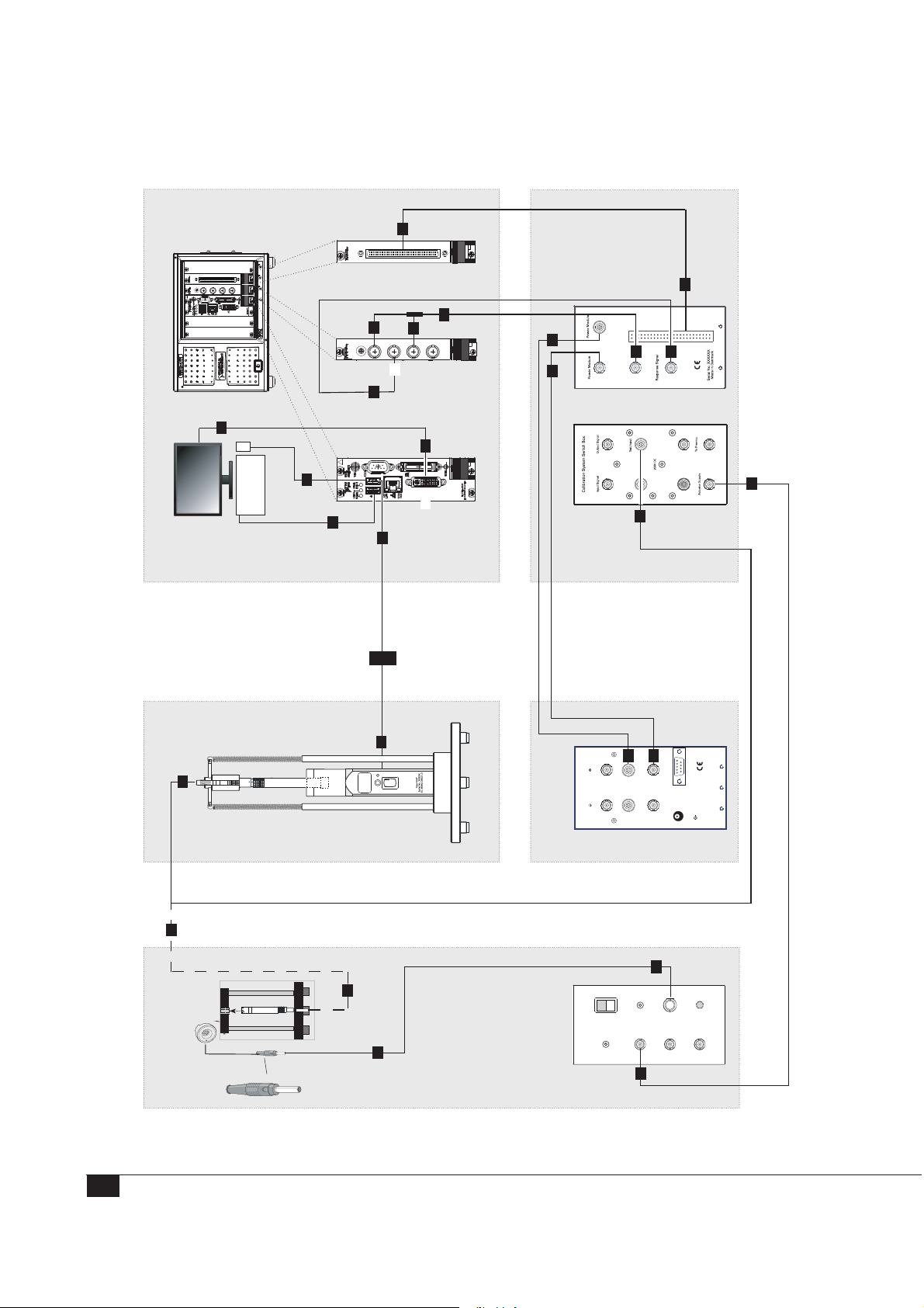
PXI: Connections for Test of Externally Polarized Microphone Sets
Important: All electrical devices must be switched off while you are setting up the
90CA.
1. Use the gray 50-position ribbon cable to connect the 6509 Digital I/O card to the
“Control Signal” socket on Switch Box RA0192 (socket on the rear).
2. Plug the BNC T-connector (two-way splitter) into the “AO 0” socket (output 0) on
the NI 4461 Dynamic Signal Acquisition Board.
3. Use a BNC cable to connect one branch of the BNC T-connector to “AI 0” socket
(input 0) on the NI 4461 Dynamic Signal Acquisition Board.
4. Use a BNC cable to connect the other branch of the BNC T-connector to the
“Excitation Signal” socket on the RA0192 Switch Box (socket on the rear).
5. Use a BNC cable to connect the “AI 1” input socket on the NI 4461 Dynamic
Signal Acquisition Board to the “Response Signal” BNC connector on the RA0192
Switch Box (socket on the rear).
6. Connect the keyboard to one of the USB slots on the PXIe 8101 Embedded
Controller.
7. Connect the mouse to the other USB slot on the PXIe 8101 Embedded Controller.
8. Connect the monitor to the DVI socket on the PXIe 8101 Embedded Controller
9. Use the control cable for the 42AP to connect it to the COM port of the Adapter
Cable with Optical Isolation and then connect this cable to a USB port of the PXI
Embedded Controller. (The PXI controller has one more USB slot than shown in the
connection diagram.)
10. Use a LEMO-to-LEMO cable to connect the “To Power Module” LEMO-socket
on the rear of the RA0192 to the Channel 1 LEMO “Input” on the 12AQ Power
Module.
11. Use a BNC cable to connect the “From Power Module” BNC-socket on the rear of
the RA0192 to the Channel 1 BNC “Output” on the 12AQ Power Module.
12. For Level calibration: Use a LEMO-to-LEMO cable (AA0008) to connect the
“Preamp Pistonphone” connector on the RA0192 to the microphone set to be
mounted in the pistonphone stand.
For Frequency calibration: Use the same cable to connect the “Preamp
Pistonphone” connector on the RA0192 Switch Box to the microphone set to be
mounted in the microphone set calibration stand.
13. Use a BNC cable to connect the “Actuator Supply” socket on the front panel of the
RA0192 to the 14AA “AC Input” socket.
14. Connect the actuator to the “+800VDC” connector on the 14AA.
21
Page 22
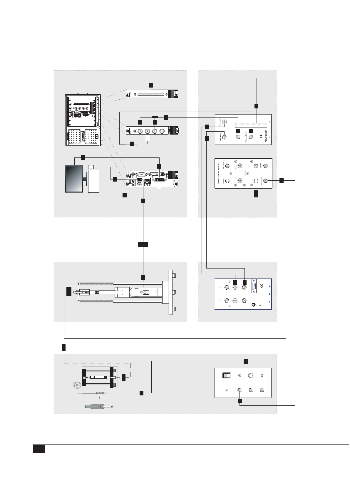
1
Digital I/O
NI PXI - 6509
1
NI PXI-e 1071 PXI Express Chassis with
Embedded Controller, Data Acquisition and I/O Cards
PXI-based System Control and Data Acquisition
12A
2
AO0
AO1
4
NI PXI - 4461
24-bit 204.8 kS/s
3
AI0
AI1
5
To
Control
Signals
From
Signal
11 10
Excitation
5
4
(TEDS)
8
Test
8
7
DVI
6
NI PXIe 8101
Embedded Controller
RA0192 Switch Box12AQ Power Module14AA Actuator Supply
Range
Extended
Frequency
RA0192
G.R.A.S.
Preamp.
Input
Preamp.
Polarization
phone
Piston-
Insert
Active
InputAdapter
Stand
Preamp. Preamp.
Actuator
13
12A
9
RS232 Adapter
Cable with
Optical Isolation
Control
Cable
9
10
11
RS232
G.R.A.S.
Pistonphone
calibration stand
42AP Pistonphone in
SysCheck
CCPInput
Channel 2 Channel 1
Output
Mic.Input
SerialNo. XXXXX
+
8-18VDC
Ext.Supply
Level Calibration Equipment
12A
PXI: Electrical Connections for Calibration of Prepolarized Microphone Sets
Calibration Stand
and Microphone Set
Electrostatic Actuator
Frequency Calibration Equipment
22
Polarization and Supply Voltage Signal Switching
14
.
4
S
.
1
A
0
.
0
R
.
A
G
R
12A
G.R.A.S.
Actuator Supply
14
Overload
Type14AA
On
Power
ACInput
Max.1Vrms
GND
+800VDC
ACOutput
+200VDC
ACOutput
ACOutput
13
Page 23

PXI: Connections for Test of Prepolarized Microphone Sets
Important: All electrical devices must be switched off while you are setting up the
90CA.
1. Use the gray 50-position ribbon cable to connect the 6509 Digital I/O card to the
“Control Signal” socket on Switch Box RA0192 (on the rear).
2. Plug the BNC T-connector (two-way splitter) into the “AO 0” socket (output 0) on
the NI 4461 Dynamic Signal Acquisition Board.
3. Use a BNC cable to connect one branch of the BNC T-connector to “AI 0” socket
(input 0) on the NI 4461 Dynamic Signal Acquisition Board.
4. Use a BNC cable to connect the other branch of the BNC T-connector to the
“Excitation Signal” socket on the RA 0192 Switch Box (socket on the rear).
5. Use a BNC cable to connect the “AI 1” input socket on the NI 4461 Dynamic
Signal Acquisition Board to the “Response Signal” BNC connector on the RA0192
Switch Box (socket on the rear).
6. Connect the Keyboard to one of the USB slots on the PXIe 8101 Embedded
Controller.
7. Connect the mouse to the other USB slot on the PXIe 8101 Embedded Controller.
8. Connect the Monitor to the DVI socket on the PXIe 8101 Embedded Controller
9. Use the control cable for the 42AP to connect it to the COM port of the Adapter
Cable with Optical Isolation and then connect this cable to a USB port of the PXI
Embedded Controller.(The PXI controller has one more USB slot than shown in the
connection diagram.)
10. Use a LEMO-to-LEMO cable to connect the “To Power Module” LEMO-socket
on the rear of the RA0192 to the Channel 1 LEMO “Input” on the 12AQ Power
Module.
11. Use a BNC cable to connect the “From Power Module” BNC-socket on the rear of
the RA0192 to the Channel 1 BNC “Output” on the 12AQ Power Module.
12. (12A) For level calibration: Use a BNC cable to connect the “Preamp Test Input”
connector on the RA0192 to the microphone set in the Pistonphone Calibration
Stand.
For frequency calibration: Use the same BNC cable to connect the microphone set
to be mounted in the Microphone Set Calibration Stand (AL0021) to the RA0192’s
“Preamp Test Input” .
13. Use a BNC cable to connect the “Actuator Supply” socket on the front panel of the
RA0192 to the 14AA “AC Input” socket.
14. Connect the actuator to the “+800VDC” connector on the 14AA.
23
Page 24
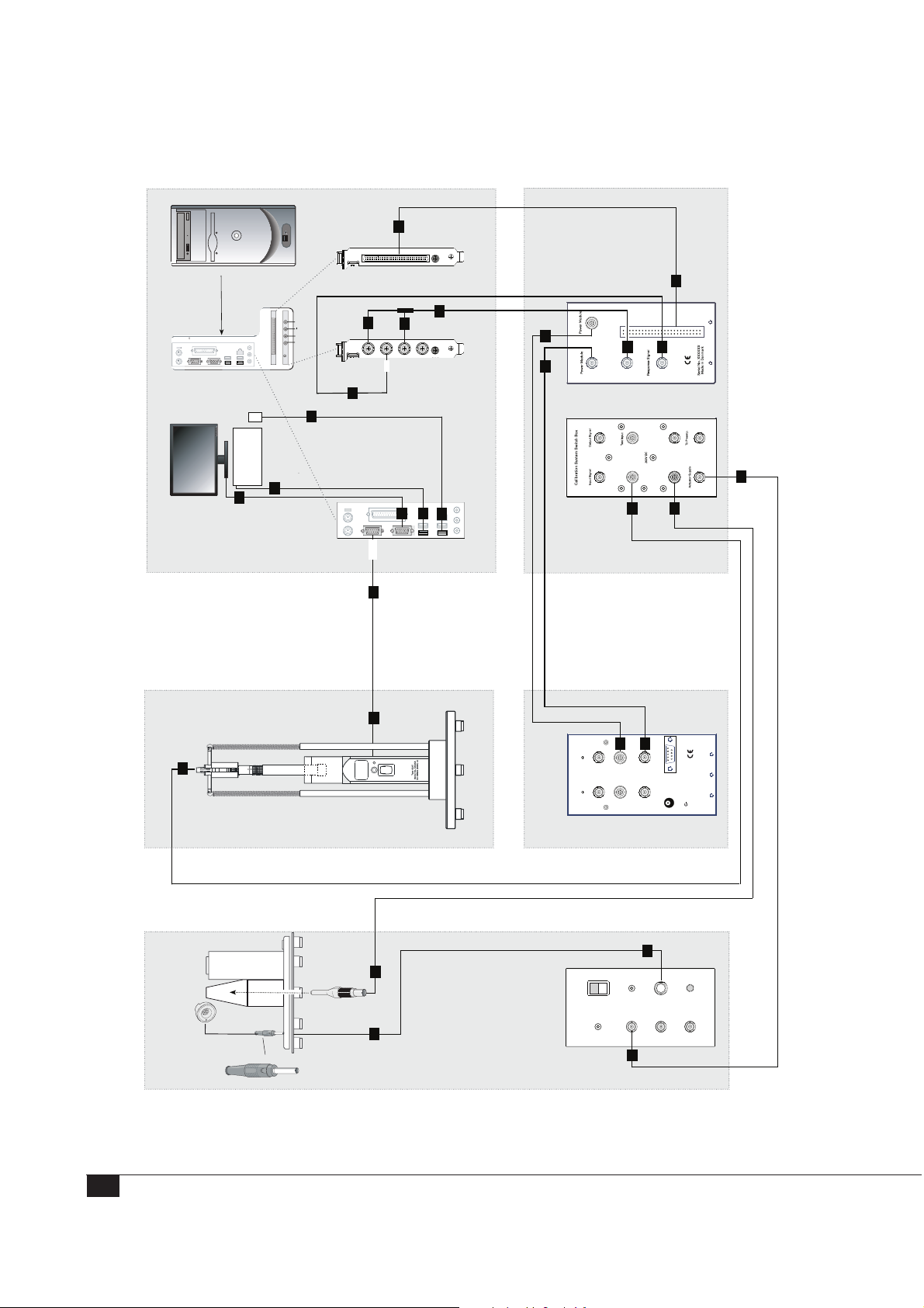
System Controller HW1000
PCI-based System Control and Data Acquisition
1
Digital I/O
NI PCI - 6503
Rear
AI0
AI1
AO0
AO1
3
AI0
AI1
2
AO0
AO1
4
24-bit 204.8 kS/s
To
Control
Signals
4
From
Signal
11 10
Excitation
1
5
(TEDS)
5
7
Test
Input
RA0192 Switch Box12AQ Power Module14AA Actuator Supply
G.R.A.S.
6
8
6
8
7
Preamp.
Range
Extended
Frequency
RA0192
Polarization
phone
Piston-
Preamp.
Insert
Active
InputAdapter
Stand
Preamp. Preamp.
Actuator
13
15
12
Level Calibration Equipment
PCI: Electrical Connections for Calibration of Microphones (Ext. Pol. and Prepol.)
.
S
.
A
.
R
.
G
Actuator Stand
Electrostatic Actuator and
VGA
COM
9
9
10
11
RS232
G.R.A.S.
Pistonphone
calibration stand
42AP Pistonphone in
SysCheck
Channel2 Channel1
Output
CCPInput
Mic.Input
SerialNo. XXXXX
+
8-18VDC
Ext.Supply
Polarization and Supply Voltage Signal Switching
14
PC Controller NI PCI - 4461
15
G.R.A.S.
Type xxxx
4
1
0
0
A
R
G.R.A.S.
Actuator Supply
14
Overload
Type14AA
On
Power
ACInput
Max.1Vrms
13 12
GND
+800VDC
ACOutput
+200VDC
ACOutput
ACOutput
Frequency Calibration Equipment
24
Page 25

PCI: Connections for Test of Microphones (Ext. Pol. and Prepol.)
Important: All electrical devices must be switched off while you are setting up the
90CA.
1. Use the gray 50-position ribbon cable to connect the 6503 Digital I/O card to the
“Control Signal” socket on Switch Box RA0192 (socket on the rear).
2. Plug the BNC T-connector (two-way splitter) into the “AO 0” socket (output 0) on
the NI 4461 Dynamic Signal Acquisition Board.
3. Use a BNC cable to connect one branch of the BNC T-connector to “AI 0” socket
(input 0) on the NI 4461 Dynamic Signal Acquisition Board.
4. Use a BNC cable to connect the other branch of the BNC T-connector to the
“Excitation Signal” socket on the RA0192 Switch Box (socket on the rear).
5. Use a BNC cable to connect the “AI 1” input socket on the NI 4461 Dynamic
Signal Acquisition Board to the “Response Signal” BNC connector on the RA0192
Switch Box (socket on the rear).
6. Connect the keyboard to one of the USB slots on the PC.
7. Connect the mouse another USB slot on the PC.
8. Connect the monitor to the VGA socket on the PC.
9. Use the control cable for the 42AP to connect it to the COM port of the computer
(PCI controller).
10. Use a LEMO-to-LEMO cable to connect the “To Power Module” LEMO-socket
on the rear of the RA0192 to the Channel 1 LEMO “Input” on the 12AQ Power
Module.
11. Use a BNC cable to connect the “From Power Module” BNC-socket on the rear of
the RA0192 to the Channel 1 BNC “Output” on the 12AQ Power Module.
12. Use a LEMO-to-LEMO cable (AA0008) to connect the “Preamp Pistonphone”
connector on the RA0192 to the (insert voltage) preamplifier to be mounted in the
pistonphone stand.
13. Use a BNC cable to connect the “Actuator Supply” socket on the front panel of the
RA0192 to the 14AA “AC Input” socket.
14. Connect the actuator to the “+800VDC” connector on the 14AA.
15. Use a LEMO-to-LEMO cable (AA0008) to connect the preamplifier to be mounted
in the electrostatic actuator stand to the RA0192’s “Actuator Stand”.
25
Page 26
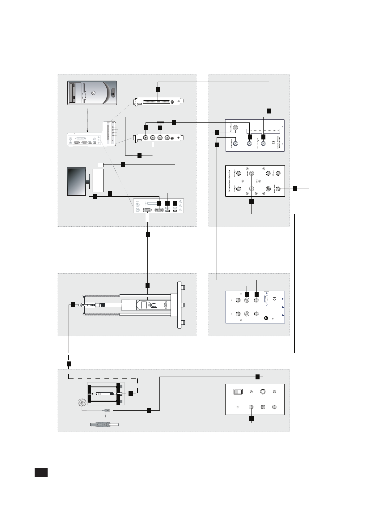
System Controller HW1000
PCI-based System Control and Data Acquisition
1
Digital I/O
NI PCI - 6503
Rear
AI0
AI1
AO0
AO1
3
AI0
AI1
2
AO0
AO1
4
24-bit 204.8 kS/s
To
Control
Signals
4
From
Signal
11 10
Excitation
1
5
(TEDS)
5
7
Test
Input
G.R.A.S.
Preamp.
Range
Extended
Frequency
RA0192
phone
Piston-
Preamp.
Insert
Active
12
RA0192 Switch Box12AQ Power Module14AA Actuator Supply
6
8
6
8
7
InputAdapter
Polarization
Stand
Preamp. Preamp.
Actuator
13
12
Level Calibration Equipment
12
PCI: Electrical Connections for Calibration of Externally Polarized Microphone Sets
.
S
.
A
.
R
.
G
Calibration Stand
and Microphone Set
Electrostatic Actuator
COM
VGA
9
9
10
11
RS232
G.R.A.S.
Pistonphone
calibration stand
42AP Pistonphone in
SysCheck
Channel2 Channel1
Output
CCPInput
Mic.Input
SerialNo. XXXXX
+
8-18VDC
Ext.Supply
Polarization and Supply Voltage Signal Switching
14
PCI Controller NI PCI - 4461
12
4
1
0
0
A
R
G.R.A.S.
Actuator Supply
14
Overload
Type14AA
On
Power
ACInput
Max.1Vrms
GND
+800VDC
ACOutput
+200VDC
ACOutput
ACOutput
13
Frequency Calibration Equipment
26
Page 27

PCI: Connections for Test of Externally Polarized Microphone Sets
Important: All electrical devices must be switched off while you are setting up the
90CA.
1. Use the gray 50-position ribbon cable to connect the 6503 Digital I/O card to the
“Control Signal” socket on Switch Box RA0192 (socket on the rear).
2. Plug the BNC T-connector (two-way splitter) into the “AO 0” socket (output 0) on
the NI 4461 Dynamic Signal Acquisition Board.
3. Use a BNC cable to connect one branch of the BNC T-connector to “AI 0” socket
(input 0) on the NI 4461 Dynamic Signal Acquisition Board.
4. Use a BNC cable to connect the other branch of the BNC T-connector to the
“Excitation Signal” socket on the RA0192 Switch Box (socket on the rear).
5. Use a BNC cable to connect the “AI 1” input socket on the NI 4461 Dynamic
Signal Acquisition Board to the “Response Signal” BNC connector on the RA0192
Switch Box (socket on the rear).
6. Connect the keyboard to one of the USB slots on the PC
7. Connect the mouse another USB slot on the PC.
8. Connect the monitor to the VGA socket of the PC.
9. Use the control cable for the 42AP to connect it to the COM port of the computer
(PCI controller).
10. Use a LEMO-to-LEMO cable to connect the “To Power Module” LEMO-socket
on the rear of the RA0192 to the Channel 1 LEMO “Input” on the 12AQ Power
Module.
11. Use a BNC cable to connect the “From Power Module” BNC-socket on the rear of
the RA0192 to the Channel 1 BNC “Output” on the 12AQ Power Module.
12. For level calibration: Use a MEMO cable to connect the “Preamp Test Input” con-
nector on the RA0192 to the microphone set in the pistonphone calibration stand.
For frequency calibration: Use the same LEMO cable to connect the microphone set
to be mounted in the microphone set calibration stand (AL0021) to the RA0192’s
“Preamp Test Input” .
13. Use a BNC cable to connect the “Actuator Supply” socket on the front panel of the
RA0192 to the 14AA “AC Input” socket.
14. Connect the actuator to the “+800VDC” connector on the 14AA
LI0028– Revision 01 March 2012
27
Page 28
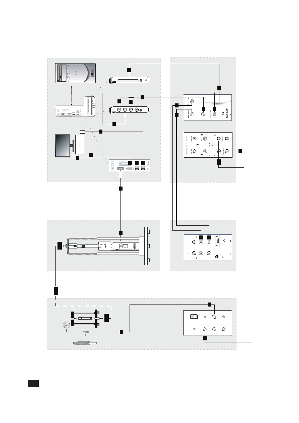
System Controller HW1000
PCI-based System Control and Data Acquisition
1
Digital I/O
NI PCI - 6503
Rear
AI0
AI1
AO0
AO1
3
AI0
AI1
2
AO0
AO1
4
24-bit 204.8 kS/s
To
Control
Signals
4
From
Signal
11 10
Excitation
1
5
(TEDS)
5
7
Test
Input
G.R.A.S.
Preamp.
Range
Extended
Frequency
RA0192
Polarization
phone
Piston-
Preamp.
Insert
Active
RA0192 Switch Box12AQ Power Module14AA Actuator Supply
6
8
6
8
7
InputAdapter
Stand
Preamp. Preamp.
Actuator
13
12A
PC Controller NI PCI - 4461
VGA
COM
9
12A
Level Calibration Equipment
12A
PCI: Electrical Connections for Calibration of Prepolarized Microphone Sets
.
S
.
A
.
R
.
G
Calibration Stand
and Microphone Set
Electrostatic Actuator
Frequency Calibration Equipment
9
10
11
RS232
G.R.A.S.
Pistonphone
calibration stand
42AP Pistonphone in
SysCheck
Channel 2 Channel1
Output
CCPInput
Mic.Input
SerialNo. XXXXX
+
8-18VDC
Ext.Supply
Polarization and Supply Voltage Signal Switching
14
4
1
0
0
A
R
G.R.A.S.
Actuator Supply
14
12A
Overload
Type14AA
On
Power
ACInput
Max.1Vrms
GND
+800VDC
ACOutput
+200VDC
ACOutput
ACOutput
13
28
Page 29

PCI: Connections for Test of Prepolarized Microphone Sets
Important: All electrical devices must be switched off while you are setting up the
90CA.
1. Use the gray 50-position ribbon cable to connect the 6503 Digital I/O card to the
“Control Signal” socket on Switch Box RA0192 (on the rear).
2. Plug the BNC T-connector (two-way splitter) into the “AO 0” socket (output 0) on
the NI 4461 Dynamic Signal Acquisition Board.
3. Use a BNC cable to connect one branch of the BNC T-connector to “AI 0” socket
(input 0) on the NI 4461 Dynamic Signal Acquisition Board.
4. Use a BNC cable to connect the other branch of the BNC T-connector to the
“Excitation Signal” socket on the RA 0192 Switch Box (socket on the rear).
5. Use a BNC cable to connect the “AI 1” input socket on the NI 4461 Dynamic
Signal Acquisition Board to the “Response Signal” BNC connector on the RA0192
Switch Box (socket on the rear).
6. Connect the keyboard to one of the USB slots on the PC.
7. Connect the mouse to another USB slot on the PC.
8. Connect the monitor to the VGA socket on the PC.
9. Use the control cable for the 42AP to connect it to the COM port of the NI PXIe
8101 Embedded Controller.
10. Use a LEMO-to-LEMO cable to connect the “To Power Module” LEMO-socket
on the rear of the RA0192 to the Channel 1 LEMO “Input” on the 12AQ Power
Module.
11. Use a BNC cable to connect the “From Power Module” BNC-socket on the rear of
the RA0192 to the Channel 1 BNC “Output” on the 12AQ Power Module.
12. (12A) For level calibration: Use a BNC cable to connect the “Preamp Test Input”
connector on the RA0192 to the microphone set in the pistonphone calibration
stand.
For frequency calibration: Use the same BNC cable to connect the microphone set
to be mounted in the microphone set Calibration stand (AL0021) to the RA0192’s
“Preamp Test Input” .
13. Use a BNC cable to connect the “Actuator Supply” socket on the front panel of the
RA0192 to the 14AA “AC Input” socket.
14. Connect the actuator to the “+800VDC” connector on the 14AA.
29
Page 30
Assembling the 90CA
This section describes the assembly of the stands for the 90CA, as well as the mounting
of the microphones, preamplifiers, and accessories.
Assembling the Calibration Stand
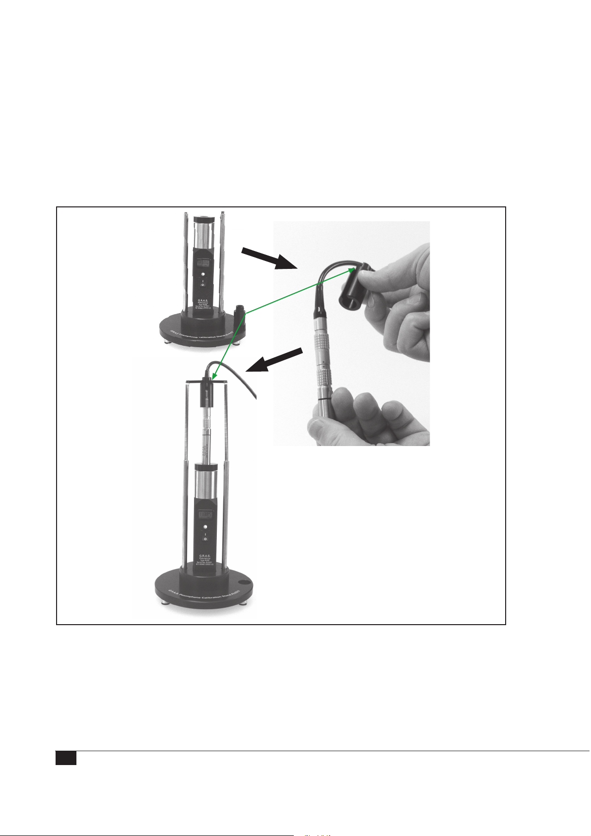
Mount the preamplifier onto the pistonphone calibration stand:
Edged side upwards
30
1. Using the cable labeled 12 or 12A in the electrical connections diagrams on the
previous pages, connect the preamplifier to the input of the RA0192 Switchbox.
2. Connect the COM port of the computer with the 42AP control input using the
control cable delivered with the 42AP (the cable labeled 9 shown in the electrical
connections diagrams).
Page 31
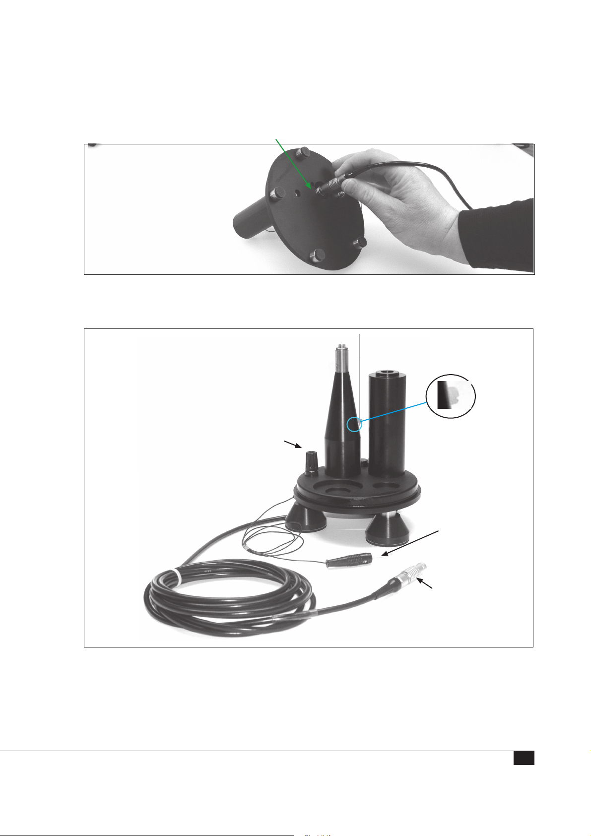
Actuator Stand Assembly
1. Insert the preamplifier into the actuator calibration stand AL0010
2. Secure the preamplifier with the grub screw/finger screw (shown in the following
figure)
Socket for plug
on electro-static
actuator
Preamplifier
Grub screw/finger screw
To Actuator
Supply 14AA
LEMO plug of
preamplifier to
Switch Box
3. Connect the actuator to the “+800 V DC” connector on the 14AA.
4. Connect the preamplifier to the RA0192 Switch Box using the cable labeled
12A/15 (LEMO to LEMO) in the electrical connections diagrams.
31
Page 32

Settings for the Instruments included in the System
In addition to the instructions in this section, always read the manuals supplied with the
individual products.
Power Module 12AQ
For all types of microphones, the following settings apply
• Polarization: 200V
• Gain: “0”
• Filter: “High Pass”
• Preamp Voltage: ±60V
Note: The system automatically compensates for the free-field correction of free-field
microphones. For prepolarized microphones, the polarization voltage is automatically
switched off, that is, you do not have to manually switch the RA0192 polarization
switch from 200V to 0V).
Electrostatic Actuator Amplifier 14AA
This amplifier must be set to the correct local mains power voltage. Default setting is
230VAC. For information about changing the setting, see the 14AA manual.
Precautions for certain Types of Microphones
Frequency calibration of 1” microphones
Be extremely careful not to scratch the microphone diaphragm when using the RA0015.
The three glass pins at the RA0015 electrostatic actuator for 1” microphones are
designed to be placed directly on the edge of the microphone diaphragm.
Microphones with non-removable protection grid
Frequency calibration is not feasible for microphones with non-removable protection
grids.
Powering on the 90CA
1. Connect the power cable and power supply for each device.
2. Turn on the power for each device.
32
Page 33
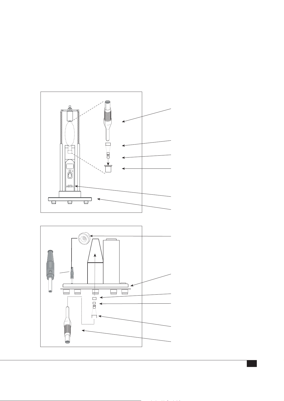
Mounting the Microphones
Externally Polarized and Prepolarized G.R.A.S. Microphones
⅛"
All the items you need for level and frequency calibration of an ⅛” G.R.A.S. microphone
are shown on this page.
Level Calibration
26AN Preamplifier, insert voltage
G.R.A.S.
Type xxxx
RA0063
⅛”
RA0069 ½” to ⅛” (Pistonphone)
Adapter
G.R.A.S.
Pistonphone
to ¼” Adapter
⅛”
microphone (DUT)
42AP Pistonphone
AL0017 Calibration Stand
Frequency Calibration
.
R
A
.
.
S
G
.
R
A
0
4
0
1
RA0014 Electrostatic Actuator
AL0010 Calibration Stand
GR0515 ⅛” to ¼” Adapter (for
Actuator)
microphone (DUT)
⅛”
Type xxxx
G.R.A.S.
RA0063 ⅛” to ¼” Adapter
26AB ¼” preamplifier with
integrated LEMO connector
33
Page 34
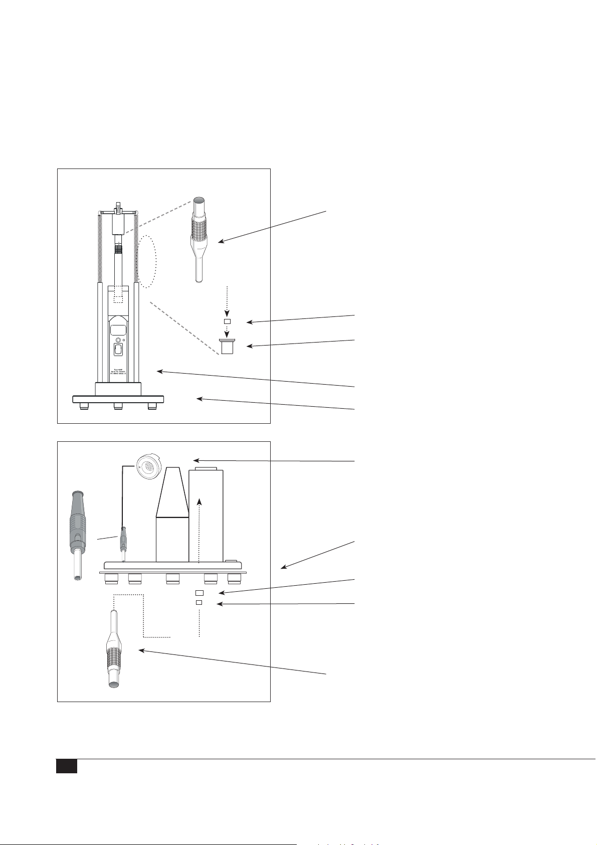
¼” Externally Polarized and Prepolarized G.R.A.S. Microphones
All the items you need for level and frequency calibration of an ¼” G.R.A.S. microphone
are shown on this page.
Level Calibration
26AN Preamplifier, insert voltage
G.R.A.S.
Type xxxx
¼” microphone (DUT)
RA0049 ¼” to ½” (Pistonphone)
Adapter
G.R.A.S.
Pistonphone
42AP Pistonphone
AL0017 Calibration Stand
Frequency Calibration
.
R
A
.
.
S
G
.
R
A
0
4
0
1
RA0014 Electrostatic Actuator
AL0010 Calibration Stand
GR0324 ¼” to ½” Adapter (for
Actuator)
Type xxxx
G.R.A.S.
¼” microphone (DUT)
26AB ¼” preamplifier with
integrated LEMO connector
34
Page 35
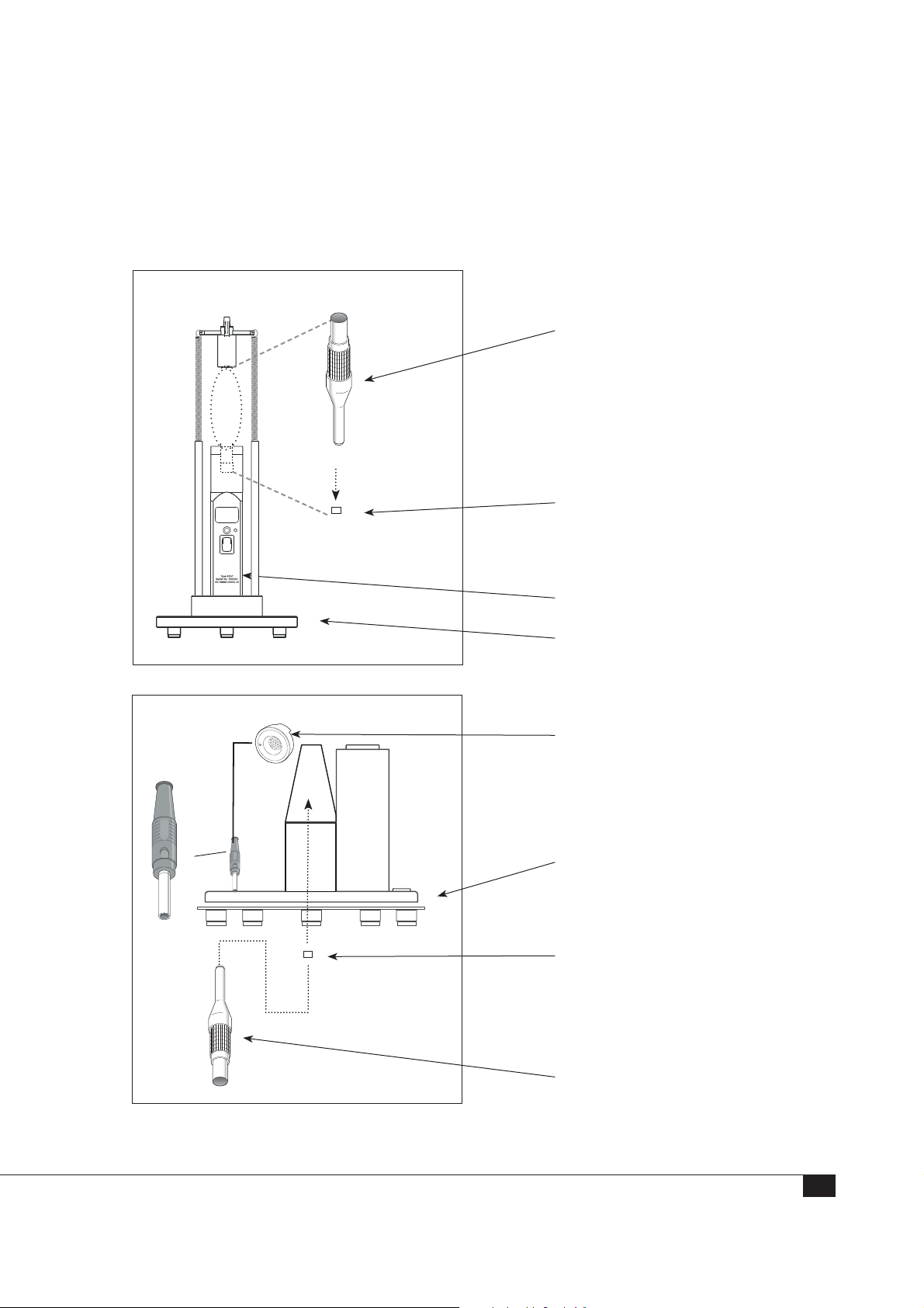
½” Externally Polarized and Prepolarized G.R.A.S. Microphones
All the items you need for level and frequency calibration of an ½” G.R.A.S. microphone
are shown on this page.
Level Calibration
26AG ½” Preamplifier, insert voltage (26AN ¼” Preamplifier, insert
voltage can be used with G.R.A.S.
½” microphones, as shown)
G.R.A.S.
Type xxxx
½” microphone (DUT)
G.R.A.S.
Pistonphone
42AP Pistonphone
AL0017 Calibration Stand
Frequency Calibration
.
R
A
.
.
S
G
.
R
A
0
4
0
1
RA0014 Electrostatic Actuator
AL0010 Calibration Stand
½” microphone (DUT)
Type xxxx
G.R.A.S.
26AB ¼” preamplifier with
integrated LEMO connector and
AF0008 ¼” to ½” Adapter - for
G.R.A.S microphones only. A 26AK
½” preamplifier can also be used.
35
Page 36
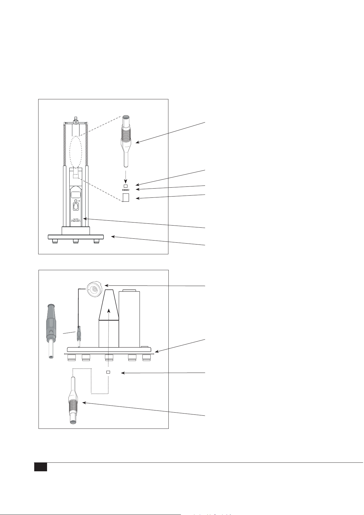
1” Externally Polarized G.R.A.S. Microphones
All the items you need for level and frequency calibration of an
1
⁄8” G.R.A.S. microphone
are shown on this page. Only the Device Under Test is not included.
Level Calibration
26AG ½” Preamplifier, insert
voltage
G.R.A.S.
Type xxxx
1” microphone (DUT)
RA0017 Adapter
RA0023 coupler replaces the
standard coupler on the pistonphone
G.R.A.S.
Pistonphone
(See manual for 42AP)
42AP Pistonphone.
AL0017 Calibration Stand
.
R
A
.
.
S
G
.
R
A
0
4
0
1
Frequency Calibration
RA0015 Electrostatic Actuator
AL0010 Calibration Stand
1” microphone (DUT)
Type xxxx
G.R.A.S.
26AB ½” preamplifier with
integrated LEMO connector
and RA0017 AdapterSystem
Verification
36
Page 37
Initial verification of the system setup
When you have assembled the 90CA, you can verify that the system is working properly
by performing a calibration of the ½” 40AG pressure microphone that is included as
reference.
Day-to-day Verification
The 90CA calibration system has been tested by G.R.A.S. Sound & Vibration and is
delivered with a test certificate for the complete system, specific instruments, and their
serial numbers listed. The 90CA is a very stable system that will calibrate to very tight
tolerances.
For daily reference instruments check, use the 40AG Reference Microphone. We recommend a verification on a daily basis – or prior to each calibration session if the system is
not used regularly.
This helps you to ensure that all system parameters remain stable. You can also ensure
that your calibrations are traceable to a reference. The 40AG reference microphone is
part of the 90CA for exactly this purpose.
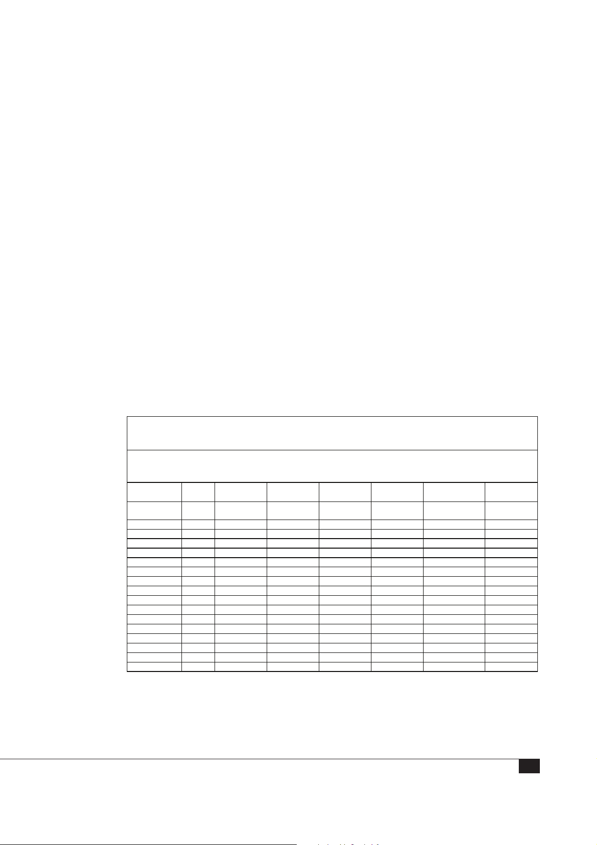
The following figure shows an example of a log of a daily system verification. This
verification consists of a level calibration of the 40AG, including the key parameters of
the measurement: temperature, humidity, barometric pressure, and polarization voltage.
Calibration System Verification
System:
Primary Lab 1
Date Time Operator Temperature Humidity Barometric
Pressure
Initials °C % RH mBar 40AG
02 Jan 2012 10:45 RH 23.0 28 1006 46466 –39.42
03 Jan 2012 09:58 RH 23.0 31 0994 46466 –39.40
04 Jan 2012 10:14 RH 24.8 29 1022 46466 –39.41
09 Jan 2012 10:16 RH 24.0 31 1028 46466 –39.42
10 Jan 2012 07:20 PA 23.0 30 1030 46466 –39.42
11 Jan 2012 08:47 PA 21.9 32 0998 46466 –39.42
12 Jan 2012 07:59 RH 24.0 33 1011 46466 –39.44
Fig. 9. Example of a calibration log
Reference
Microphone
Serial number
Sensitivity
dB re 1V/Pa
37
Page 38
Introducing the Calibration Software SW0002
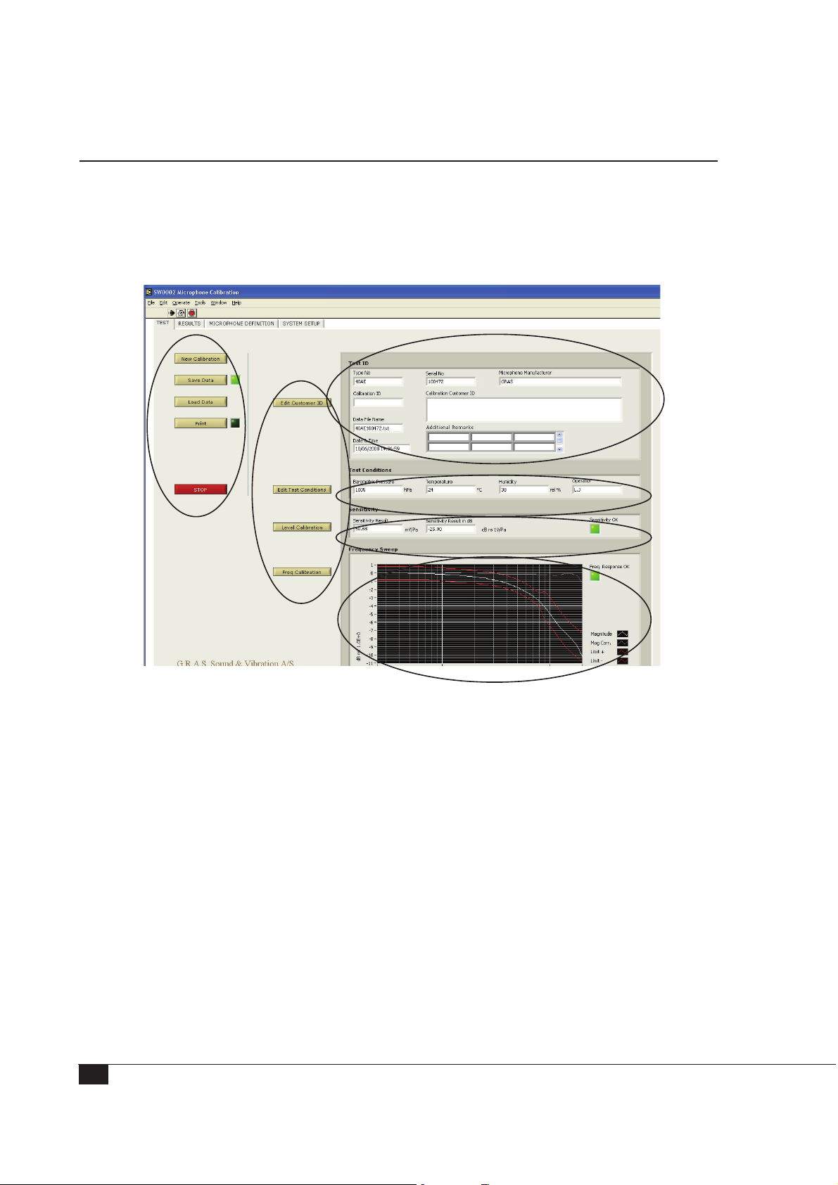
The 90CA is delivered with the software preinstalled. It can be launched from the
desktop as with any Windows application.
IMPORTANT. If you decide to install a new version of LabView, DO NOT uninstall the
version that comes with the system, because if you do, the calibration software will not
work properly, or at all.
1
2
6
5
3
4
Fig. 10. The 90CA main window for microphone calibration
The main screen offers the following:
1. A conventional software menu bar
2. Tabs where you select the different parts of the calibration process: TEST, where
you work during the calibration; RESULTS, where you view the data from your
calibration; MICROPHONE DEFINITION; SYSTEM SETUP.
3. Buttons to start and stop calibration, to save, and to print.
4. Buttons for use during the calibration: Start Calibration, Level Calibration,
Frequency Calibration, and Edit Test Conditions.
7
8
38
5. The “Test Conditions” you enter are displayed here (part 1 of Microphone
Registration).
6. The “Test ID” you enter is displayed here (part 2 of Microphone Registration) .
Page 39
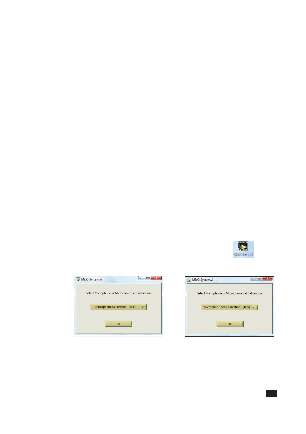
7. Measured data for the level calibration is displayed here.
8. Measured data for the frequency calibration is displayed here.
In general, the indicators are green when the measurement is within the preset limits
and red when the the measurement is outside the limits.
Calibrating Microphones and Microphone Sets
This section describes how to do a calibration of a microphone or microphone set. Your
system should already be assembled and connected as described in “Assembling and
Connecting the Hardware”.
Note: For information about high-frequency calibration, see “High Frequency Calibration”
on page 54.
Starting the System
Verify that all connections are correct and that the system is ready for calibration. We
recommend a daily system verification using the 40AG as reference microphone. If such
a verification is performed regularly, you can ensure that all parts of the system are
performing properly and within specification. Keeping a daily log will ensure traceability
and that any errors can be detected early.
1. Start up the system controller.
2. Switch on the 12AQ power module, the 14AA electrostatic actuator amplifier, and
the 42AP pistonphone.
Note: Allow up to 20 minutes for the power module to warm up (for the polarization
voltage to stabilize.)
3. To start the calibration software, double-click on the desk-top icon:
You can now choose Microphone Calibration or Microphone Set Calibration
Fig. 11. Selecting microphone calibration or microphone set calibration
4. Your screen displays the start-up screen with the Test Conditions dialog box in the
foreground:
39
Page 40
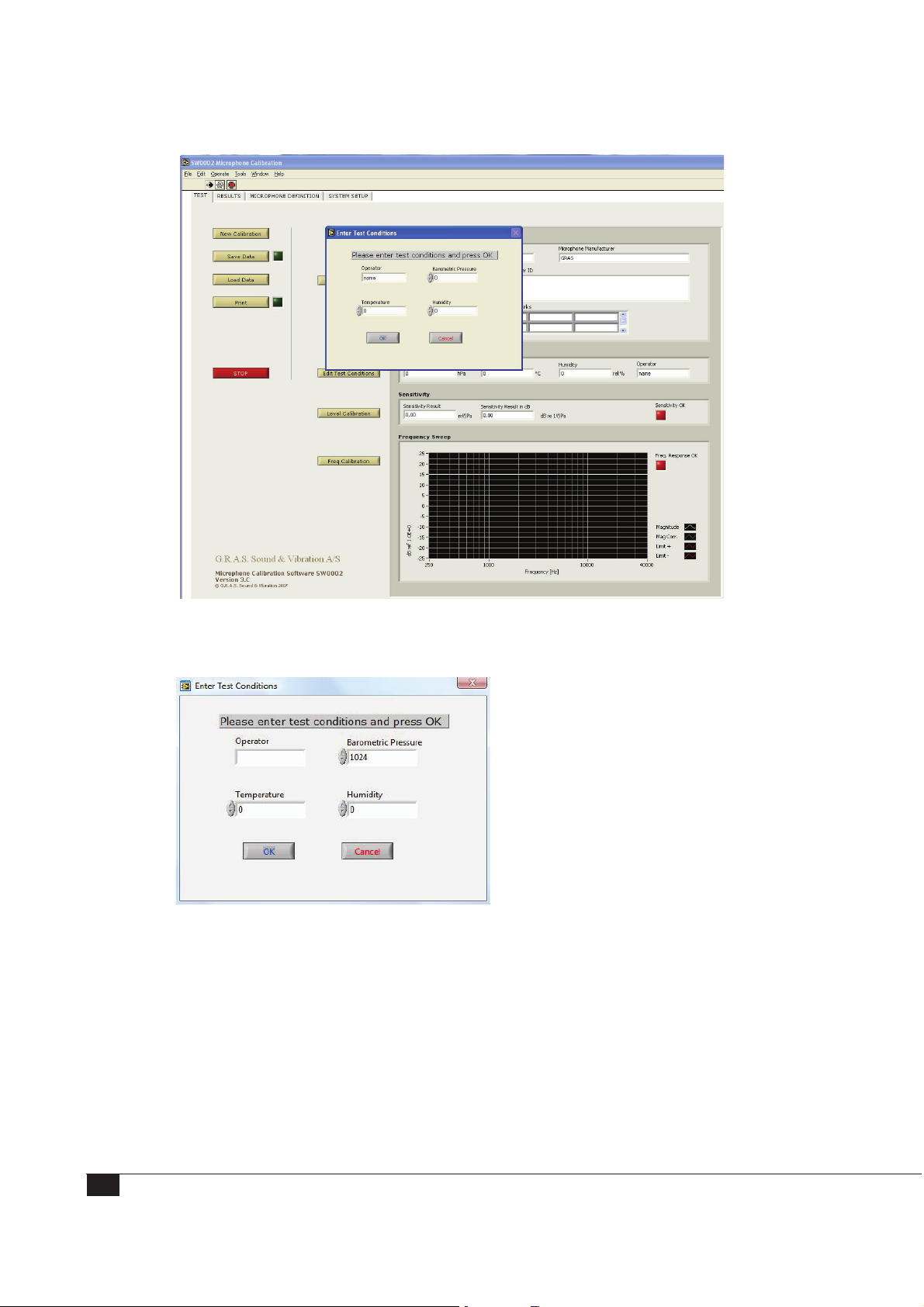
5. Enter Test Conditions:
40
1
3
5
2
4
1. Enter your name or other identification here.
2. The 42AP pistonphone supplies this information automatically. If the 42AP is not
connected to the COM port, enter the barometric pressure [hPa] manually, e.g.
“1005”.
3. Type in the temperature [°C], e.g. “22 “.
4. Type in the relative humidity [%], e.g. “42”.
5. To save your data, press “OK”.
Page 41
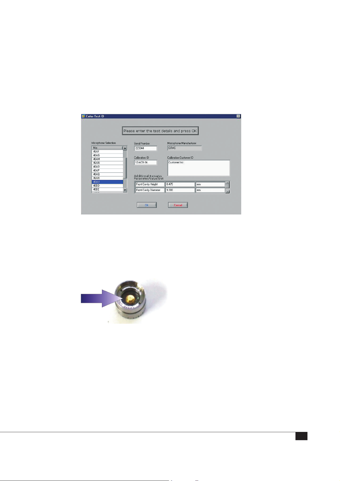
Step 1: Registering the Microphone
1. Click New Calibration and the Test Details dialog box opens. Select a microphone
type from the list, enter serial number, Calibration ID, and Customer ID (if needed).
The Microphone Manufacturer name is defined in the Microphone Definition File.
The Additional Remarks are for any special remarks, such as front cavity height and
diameter of a 40AU LS2aP microphone.
The system includes definitions for all G.R.A.S standard microphone types. For a
non-G.R.A.S. microphone to appear in the selection menu, you must have registered
the microphone in the Microphone Definition File.
2. Carefully inspect the microphone output terminal for dust and dirt. If necessary, clean
with compressed air or a small brush.
41
Page 42
Step 2: Performing a Level Calibration
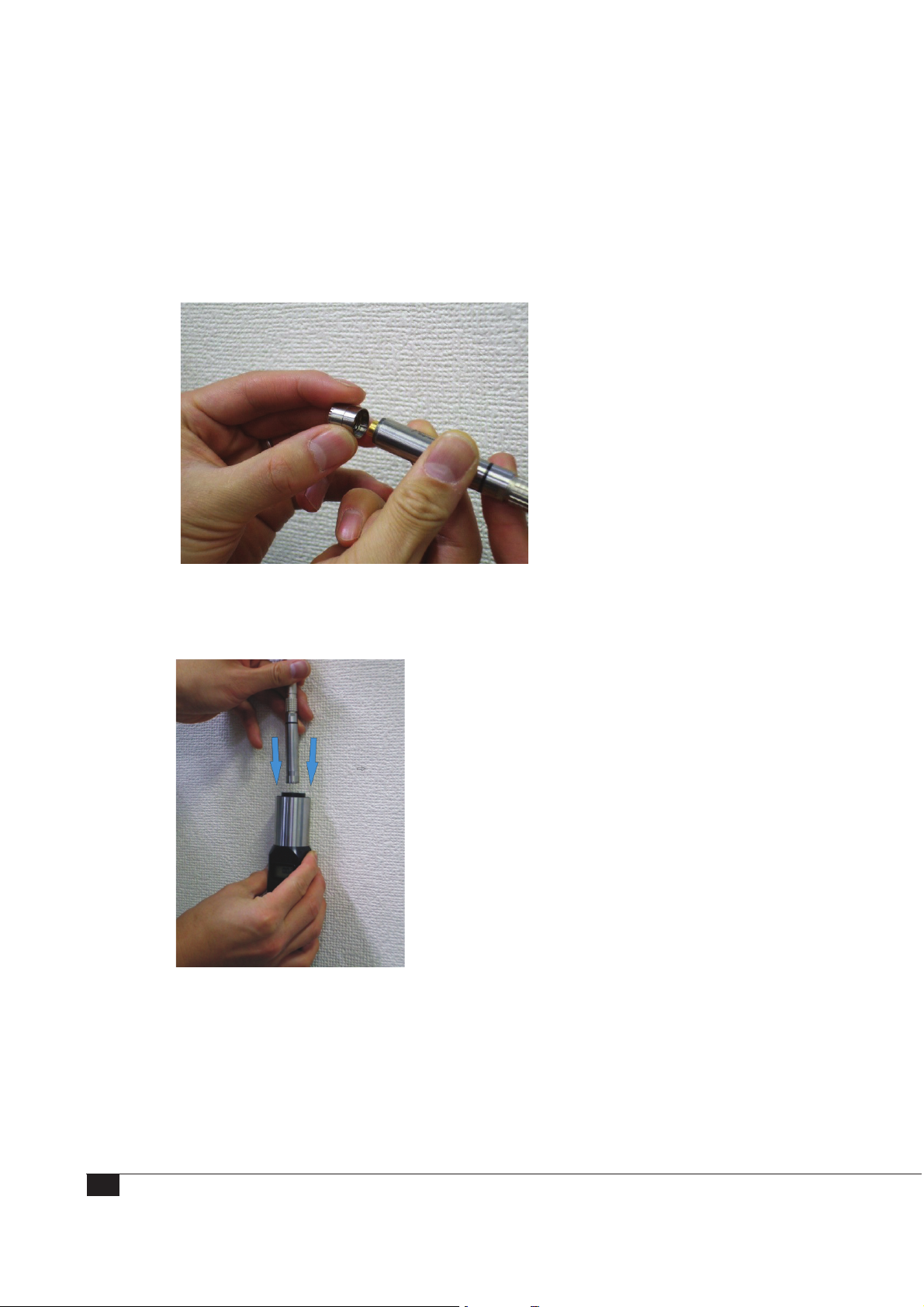
1. Mount the microphone onto the preamplifier:
• 26AG for ½” microphones
• 26AN for ¼” microphones
2. Place the microphone into the pistonphone 42AP.
Note: Make sure the microphone is inserted all the way into the coupler.
3. In the main menu, click Level calibration.
42
Page 43
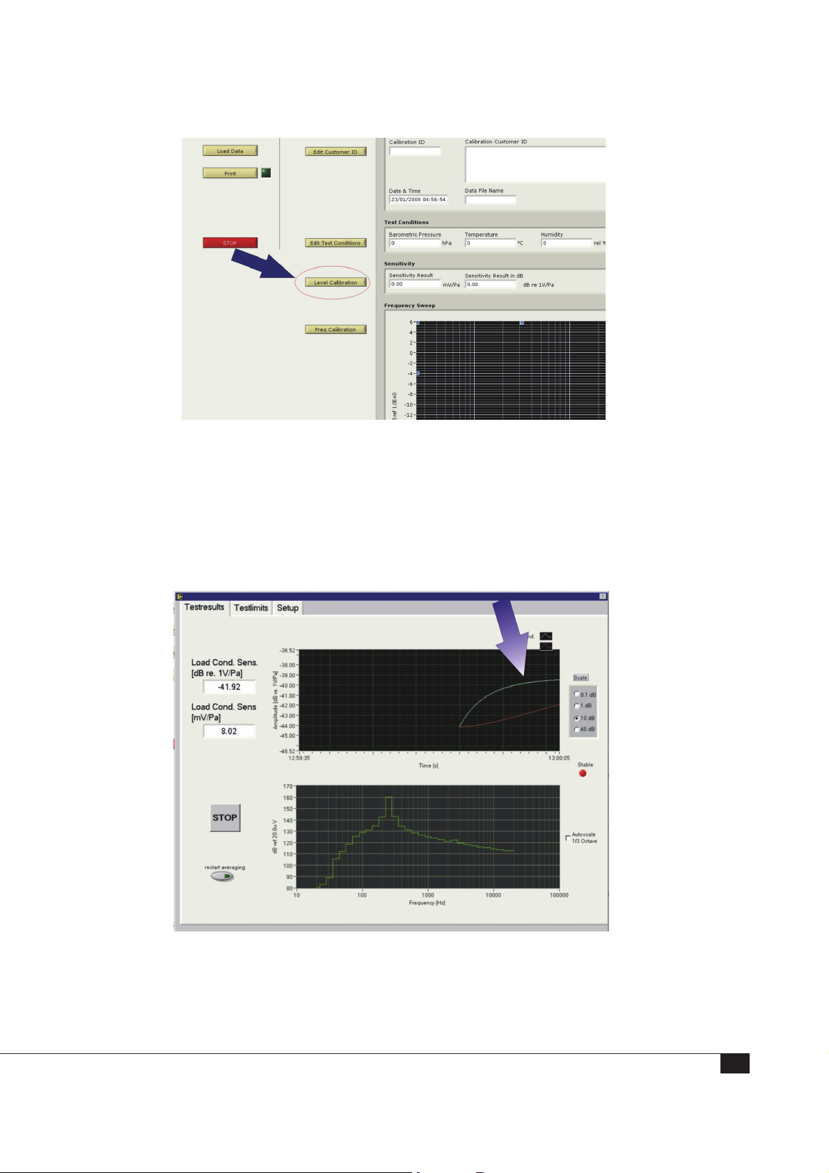
The software measures the difference between open-circuit and closed-circuit sensitivity. The test has two different steps which appear automatically; first, a closed-circuit
sensitivity measurement, and then an insert-voltage measurement to measure the
open-circuit sensitivity.
In the first step, the closed circuit sensitivity measurement – two curves, gradually
converging – are displayed:
A
B
The top, white curve (A) represents the instantaneously measured sound pressure level:
The bottom, red curve (B) represents the averaged value of the sound pressure level.
43
Page 44
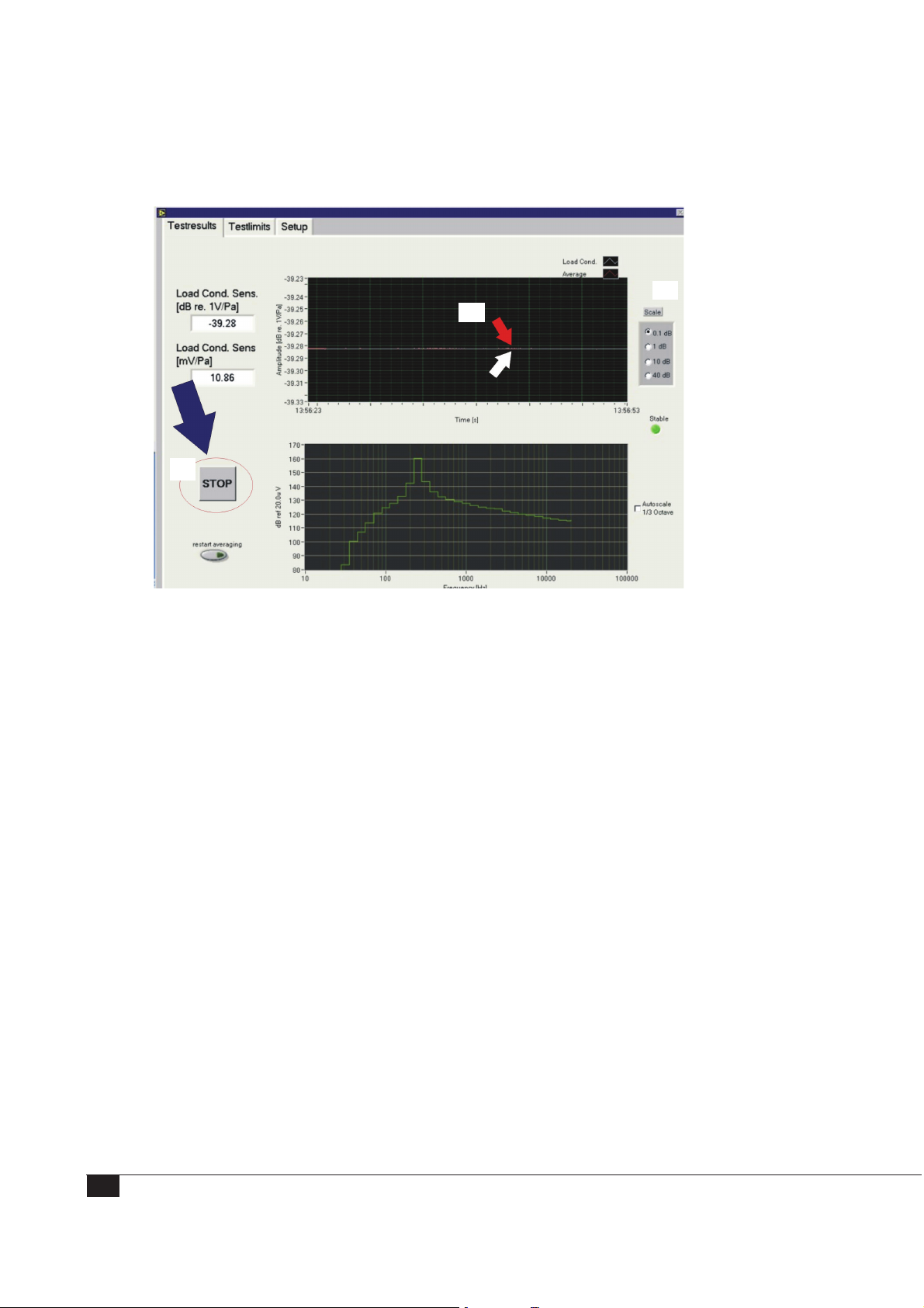
4. The amplitude scale (C) is initially set to 10 dB. As the curves approach each other,
it is recommended to downscale first to 1 dB, and finally to 0.1 dB:
C
A
B
5. When the signals have stabilized (A), click STOP (B). Then, a new window opens
and the software switches off the pistonphone (pistonphone LED red) and starts
measuring the open-circuit sensitivity by the insert voltage method.
Note: The scale (C) is set to 0.1 dB.
6. When the signals have stabilized, click OK and the sensitivity test is finished. Now
in the main window, the open-circuit sensitivity will be displayed and an indicator will be green if the sensitivity is verified as OK compared to the microphone
definitions.
44
Page 45
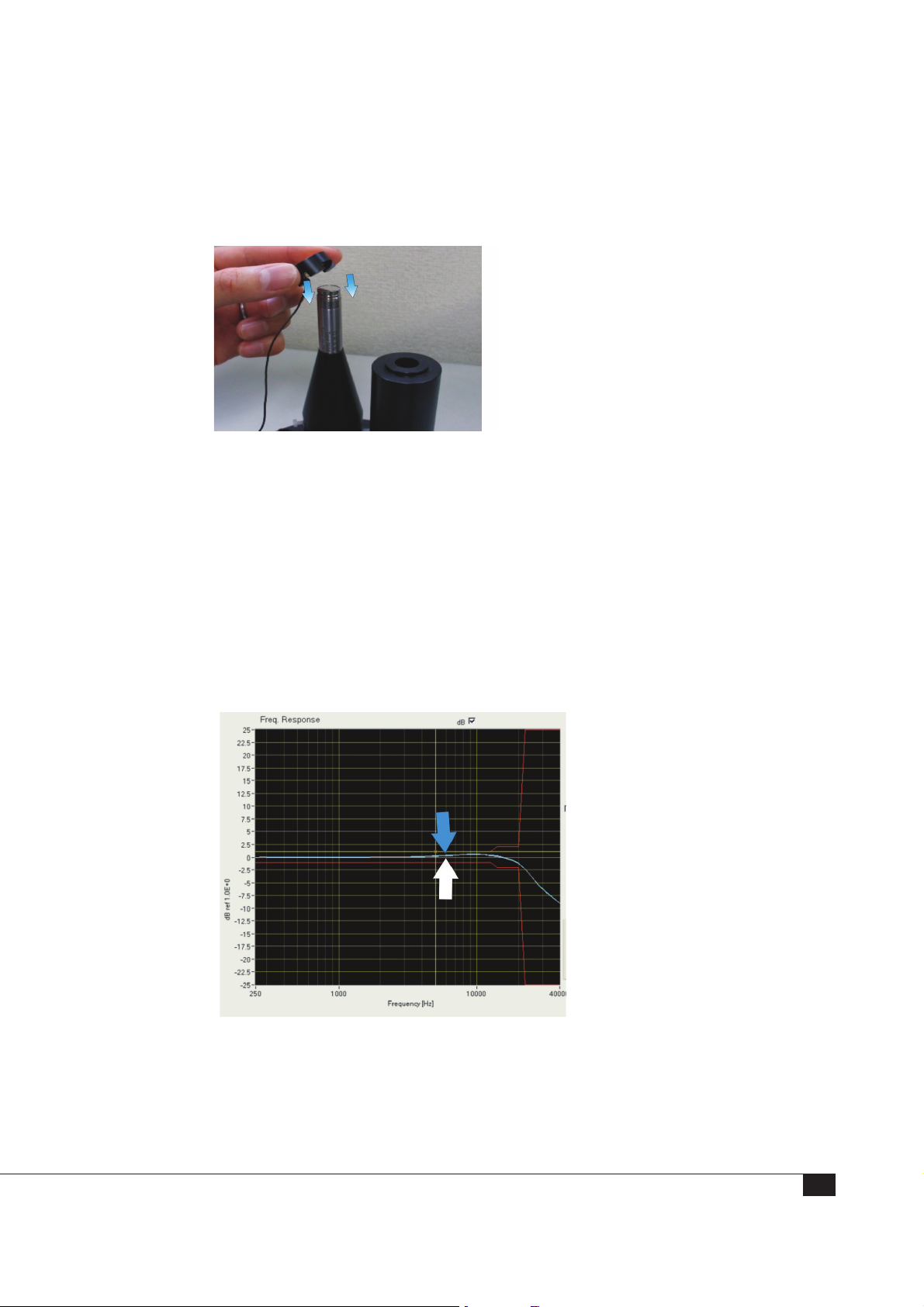
Step 3: Performing a Frequency Response Calibration
1. Mount the microphone onto the preamplifier in the AL0010 Frequency Calibration
Stand
2. Carefully unscrew the microphone protection grid.
3. Place the electrostatic actuator onto the microphone diaphragm
4. In the software main menu, click FreqCalibration and a new window opens. This
window has a menu bar with the following features: Measurement, Test limits,
Setup, and Debug. For measurement, it’s only necessary to use the Measurement
mode. The rest is only for debugging and information about the setup.
5. Then click Start Measurement
The calibration system displays three curves and the upper and lower test limits for
the specific microphone type:
The white curve indicates the most
recently measured level
The blue curve indicates the previously
measured level.
The yellow curve indicates the free field
corrections
The red lines indicate the upper and
lower limits for the specific microphone
6. Run the test a couple of times to ensure the microphone capsule is vented. When
the white and the blue curves have stabilized, click Accept.
Note: If the “Overload” LED is red, the measurement is probably not valid.
45
Page 46
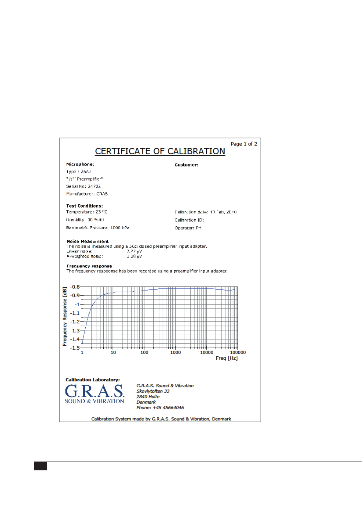
Step 4: Storing Calibration Results
To store the data measured, click Save Data. The data will be stored at a path defined
in the Microphone Definition File.
To generate a calibration certificate, click Print.
Note: The 90CA does not include a printer. You must install a printer to print
certificates.
46
Fig. 12. Typical G.R.A.S Calibration Chart
Page 47
Calibrating a Preamplifier
This section describes how you set up the system for calibration of the preamplifiers and
walks you through a typical calibration workflow.
Note: Calibrating preamplifiers is an option package for the 90CA. (Option OP0020).
All preamplifiers except insert-voltage preamplifiers and preamplifiers with SysCheck
can be calibrated with the 90CA.
Note: For information about high-frequency calibration, see “High Frequency Calibration”
on page 54.
Setting up the System for Preamplifier Calibration
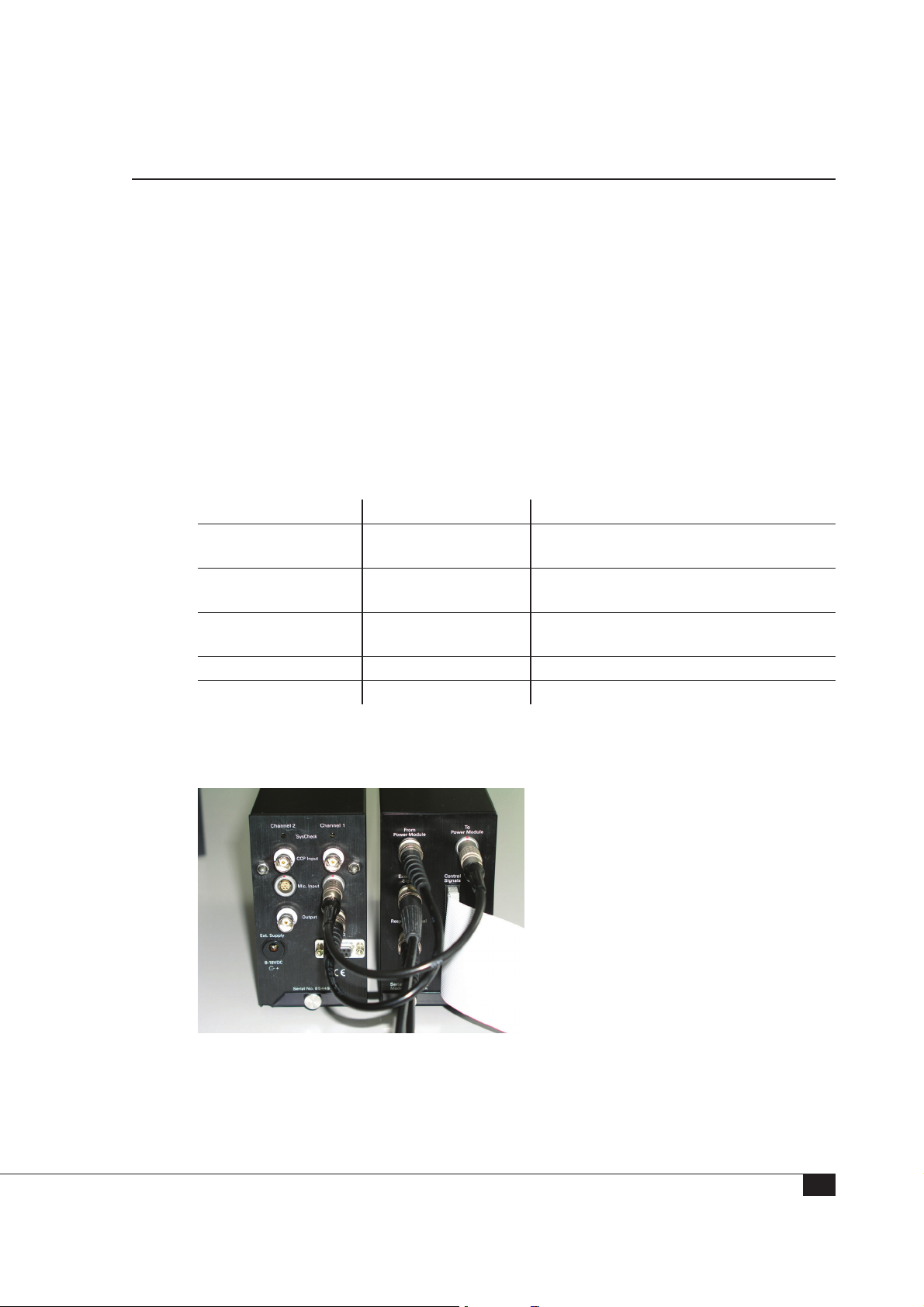
The first step in preamplifier calibration is connecting the switchbox to the system. The
following table shows which switchbox output to connect to either the system controller
or the power module.
Switchbox Slot Connect With To
Excitation Signal BNC cable AO0 on NI Card 4461 in System
Response Signal
(TEDS)
Control Signals 50-conductor ribbon
From Power Module BNC cable Output connector on power module
To Power Module 7-pin LEMO cable Mic. Input connector on power module
Controller
BNC cable AI1 on NI Card 4461 in System
Controller
NI Card PCI-6503 in computer or PXI-
cable
6509 in PXie 1071 PXI Express Chassis
The following image shows the connections between the switchbox and the power
module.
When the switchbox is connected to the power module and the system controller, you
are ready to use the software for running the calibration programs.
47
Page 48

Step 1: Registering Test Conditions
In preparation for your calibration,
1. Disconnect all cables on the front panel of the RA0192 switchbox.
2. Connect the 42AP pistonphone to the power module and turn on the pistonphone.
3. On your PC desktop, start the preamplifier calibration by double-clicking the
PreAmp calibration icon to open the software control panel.
4. When the software control panel opens, a smaller window also opens where you
register the test conditions for the preamplifier.
5. Because the 42AP pistonphone is connected and turned on, the field for the
barometric pressure in hPa is automatically filled in.
You must provide
— the initials or name of the person running this calibration (operator),
— the current temperature in °C,
— and the relative humidity in %.
6. Click OK to add the information; you are returned to the main screen.
There is one main window for the preamplifier calibration software. This window is
shown in the following screenshot.
48
Page 49
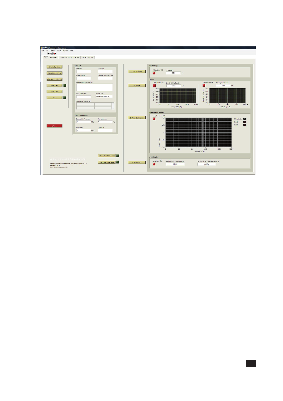
Fig. 13. The 90CA main window for preamplifier calibration
This main window is where you can
• Start a new calibration • Measure the noise floor (linear and A-weighted)
• Edit the customer ID • Measure the frequency response
• Edit the test conditions • Measure the relative sensitivity
• Save data to a .txt file • Measure the LEMO reference level (must be
done before you can measure the sensitivity)
• Load data from a previously
saved data file
• Measure the CCP reference level (must be done
before you can measure the sensitivity)
• Print • Stop a calibration process
• Measure DC voltage of a
preamplifier
Registering a New Calibration
After you establish the test conditions, you can start a new calibration.
1. On the main screen, click New Calibration; a new window opens.
2. Select the correct preamplifier type that you are about to test.
49
Page 50

3. Enter the serial number for the preamplifier.
The remaining fields are optional and can be used to suit your classification system.
Additional information can be valuable when you have a large amount of calibration
data in your archives.
4. Click OK; this window closes and you return to the main screen.
Measure the DC Voltage
1. (Skip this step for preamplifiers with integrated cables.) Connect a cable to the
RA0192 system switchbox connector called “Preamp. Test Input”, choosing the
cable according to the preamplifier’s connector.
—Use the AA0008 LEMO extension cable for LEMO connectors
—Use the AA0018 microdot to BNC cable for microdot connectors
—Use the AA0027 SMB-BNC connector cable for coaxial SMB connectors.
—Use the AA0033 BNC 50-Ohm cable for BNC connectors.
2. Attach the AE0036 short circuit plug to the BNC connector end of the RA0062
preamplifier input adapter.
The RA0062 is a 20pF input adapter that is used as 20pF dummy load on the
preamplifier when you shortcircuit the BNC input.
3. Mount the RA0062 on the ½” preamplifier under test.
For ¼” preamplifiers, attach a GR0010 adapter to the ¼” preamplifier and then
attach the RA0062 preamplifier.
4. Connect the preamplifier to the cable. (Some preamplifiers already have an integrated cable.)
5. On the software main window, click DC Voltage to start the DC voltage measurement; a new window opens, which starts the measurement automatically.
6. You can monitor the current level in the DC value field and on the graph.
The diode indicates whether the current level is within the test limits: green means
it is OK; red means it is outside the limits.
7. When the measurement has stabilized and the “DC level OK” indicator is green, you
can click Stop. The window closes and the measurement results are transferred to
the main window.
When finished with the DC voltage measurement, you are ready to verify the self noise
of the preamplifier. Leave the setup as it is.
50
Page 51

Verify the Self Noise of the Preamplifier
With the same hardware setup as for the DC voltage measurement, you can measure
the self noise of the preamplifier.
1. On the main window (the software panel), press Noise. A new window opens and
the noise measurement starts automatically.
2. You can monitor the current level in the Total Noise field and on the two graphs.
The diode indicates whether the current level is within the test limits: green means
it is OK; red means it is outside the limits.
3. When the measurement has stabilized and the “20-20kHz OK” and “A-Weighted
OK” indicators are green, you can press Stop. The window closes and the measurement results are transferred to the main window.
After you record the DC voltage and self-noise, you are ready for the second step in
calibration.
Step 2: Frequency Response
1. Remove the AE0036 short circuit BNC plug from RA0062.
2. Connect a BNC cable to the BNC connector on RA0062.
3. Connect the other end of the BNC cable to the system switchbox connector called
“To Preamp. Input Adapter”.
4. On the main window, click Frequency Calibration; a new window opens where you
can start the frequency sweep measurement.
5. Click Start Measurement; the “Sweep in Progress” indicator switches on so it is a
bright red light.
6. When the measurement is completed, the indicator switches off so the indicator is
dark red.
The diodes at the top of the window—Freq. OK, Upper Limit OK, and Lower Limit
OK—indicate whether the measured sweep is within the test limits; green indicates
it is within the limits.
7. When the sweep is finished and the results (the indicators) seem satisfactory), click
Accept to close the window and transfer the measurement results to the main
window.
If you click Cancel, the window closes, but the measurement results are not
transferred to the main window.
Note: The Accept and Cancel buttons are inactive during a sweep. Click Stop
Measurement if you want to stop an active sweep.
This completes the frequency response calibration.
51
Page 52

Step 3: LEMO Reference Level and Sensitivity Test
Measuring the LEMO reference level is a necessary step before measuring the
sensitivity.
1. Remove the RA0062 from the preamplifier (and GR0010, if used).
2. Remove the preamplifier and its cable from the switchbox.
3. Connect the reference preamplifier (26AG), the reference microphone (40AG), and
the cable (AA0008) to the “Preamp. Test Input” on the switchbox.
4. Connect the 40AG to the pistonphone coupler
5. On the main window, click LEMO Reference Level to start the LEMO reference
level measurement; a new window opens.
6. Select the type of the reference microphone; in this case, select the 40AG.
7. Click OK; the window closes
8. The LEMO reference level window opens and the 42AP pistonphone turns on and
starts measuring.
9. The current level of the measurement can be seen in the Sensitivity field.
The “Sensitivity OK” diode indicates whether the current level is within the test
limits: green means it is OK; red means it is outside the limits.
10. When the measurement has stabilized and the “Sensitivity OK” indicator is green,
you can click Stop. The window closes and the measurement results are transferred
to the main window.
11. Reconnect the preamplifier, disconnected in step 2, with the reference microphone.
12. On the main window, you can click Sensitivity to begin the sensitivity measure-
ment; a new window opens. (This is the same window you saw with the LEMO
reference level window.)
13. The 42AP pistonphone turns on and starts measuring automatically when the
window opens.
14. The current level of the measurement can be seen in the Sensitivity field.
The “Sensitivity OK” diode indicates whether the current level is within the test
limits: green means it is OK; red means it is outside the limits.
15. When the measurement has stabilized and the “Sensitivity OK” indicator is green,
you can click Stop. The window closes and the measurement results are transferred
to the main window.
52
Page 53

Step 4: Storing Calibration Results
You must save and store the results before you can print a calibration sheet.
1. On the main window, click Save Data.
2. This stores the data from all the tests in a text file (.txt) on the hard drive.
The filename is generated from the preamplifier type and the serial number of the
preamplifier. For example, the file name for a 26AC preamplifier with the serial number
123456 will be 26AC123456.txt.
If the file name already exists, you can choose to create a new file or to overwrite the
existing file. Creating a new file attaches a “-1” to the name: 26AC123456-1.txt.
Printing a Calibration Sheet
On the main window, click Print.
• A calibration sheet is printed if the PC is connected to a printer.
• A PDF file is created and stored on the local hard drive at the same time.
If no printer is connected, a PDF file is always saved.
53
Page 54
High Frequency Calibration
For high frequency calibration of microphones, microphone sets, or preamplifiers, you
must use a signal generator and a digital multimeter capable of dealing with high
frequencies, for example these models provided by Keysight, or instruments with similar
specifications:
• 33210A or 35500B Signal Generator
• 34465A Digital Multimeter
Connecting the 33210A or 35500B Signal Generator and the 34465A Digital
Multimeter.
1. Use a BNC cable to connect the output of 33210A (35500B) to the “Output
Signal” (output from generator) on the RA0192.
2. Use an RS-232 cable (Null Modem) to connect the 33210A (35500B) to the
computer.
3. Configure the 33210A (35500B) as follows so it can communicate with the
computer. Under the I/O menu, add the following information:
Interface RS-232
Baudrate 9600
Parity None: 8 Bits
For more information, see the 33210A (35500B) manual.
4. Use a BNC cable to connect the input of 34410 to the “Input Signal” (input for
multimeter) on the RA0192.
5. Use an RS-232 cable (Null Modem) to connect the 34465A to the computer.
6. Configure the 34410 as follows so it can communicate with the computer. Under
the I/O menu, add the following information:
Interface RS-232
Baudrate 9600
Parity None: 8 Bits
For more information, see the 34410 manual.
7. Go to the setup file and enter the correct COM port for the 33120A and 34465A,
and enter the “Cut-off Frequency” (the frequency where the system starts to use the
external signal generator and multimeter); save the file.
When the setup is configured correctly and the connection of the signal generator and
the multimeter is done, the system is ready for high frequency calibration.
54
Page 55

Calibrate the device as usual; the system automatically switches between using the data
acquisition card in the computer and the external signal generator and the multimeter.
The “Cut-off Frequency” entered in the setup file must be included in the frequency list
in the definition file. Otherwise, the system cannot switch correctly between using the
data acquisition card in the computer and using the external devices.
For example, if a 40DP microphone has a frequency list like the following
....56000, 63000, 71000, 80000, 90000, 100000, 112000, 125000, 140000,
160000, 180000, 200000
then the “Cut-off Frequency” must be one of these frequencies.
If the “Cut-off Frequency” is set to 92 kHz, then
• All frequencies up to 92kHz (including 100kHz) in the list will be measured by
the data acquisition card in the computer.
• Frequencies above 92 kHz will be measured using the 33210A (35500B)
generator and the 34465A multimeter.
Note: The system will automatically change the output termination of the 33210A
(35500B) signal generator to 50 . If the generator was originally set to “High Z”, then
the system will not set the output termination back to “High Z”. Setting it back must be
done manually, if needed.
Note: The sampling rate is 204.8 kHz. Therefore, the cut-off frequency should not be
set to a value much higher than 92 kHz to avoid aliasing.
55
Page 56

Working with the System Files and Documentation
There are several files used by the 90CA that you can edit. This section describes the
location of those files and how you can edit and store them.
Viewing and Editing the Microphone and Preamplifier Definition Files
All the microphone and preamplifier definitions used by the 90CA are stored in the
“Microphone Definition file” and “Preamplifier Definition file”. These files can be read
and edited in Notepad or (preferably) in Excel.
C:\Program Files\GRAS Sound & Vibration\SW0002\Microphone Definition file.txt
C:\Program Files\GRAS Sound & Vibration\SW0002\Preamplifier Definition file.txt
Note: The system was designed with a fixed set of parameters for each microphone or
preamplifier. You can add definitions of new microphones or preamplifiers to this file, but
you cannot remove or add parameters to the fixed set of 22 for microphones or 28 for
preamplifiers.
These files contain pre-set test parameters for Level Calibration and Frequency
Calibration. Test parameters are pre-set for G.R.A.S. products only.
Adding a new microphone or preamplifier to the definition file
The procedure is the same for microphones and preamplifiers.
1. Collect the data for the new microphone or preamplifier.
2. Create a copy of the existing microphone definition file;
name it <filename>.new.
3. Rename the existing microphone definition:
name it <filename>OLD.txt
4. Open <filename>.new with either Excel or Notepad.
5. For a new microphone, copy the first 23 lines.
For a new preamplifier, copy the first 28 lines.
6. Paste these lines at the bottom of the file.
7. Edit these new lines according tp the data you collected.
8. Save this file as a text file: <filename>.txt.
9. Test the file.
56
Page 57
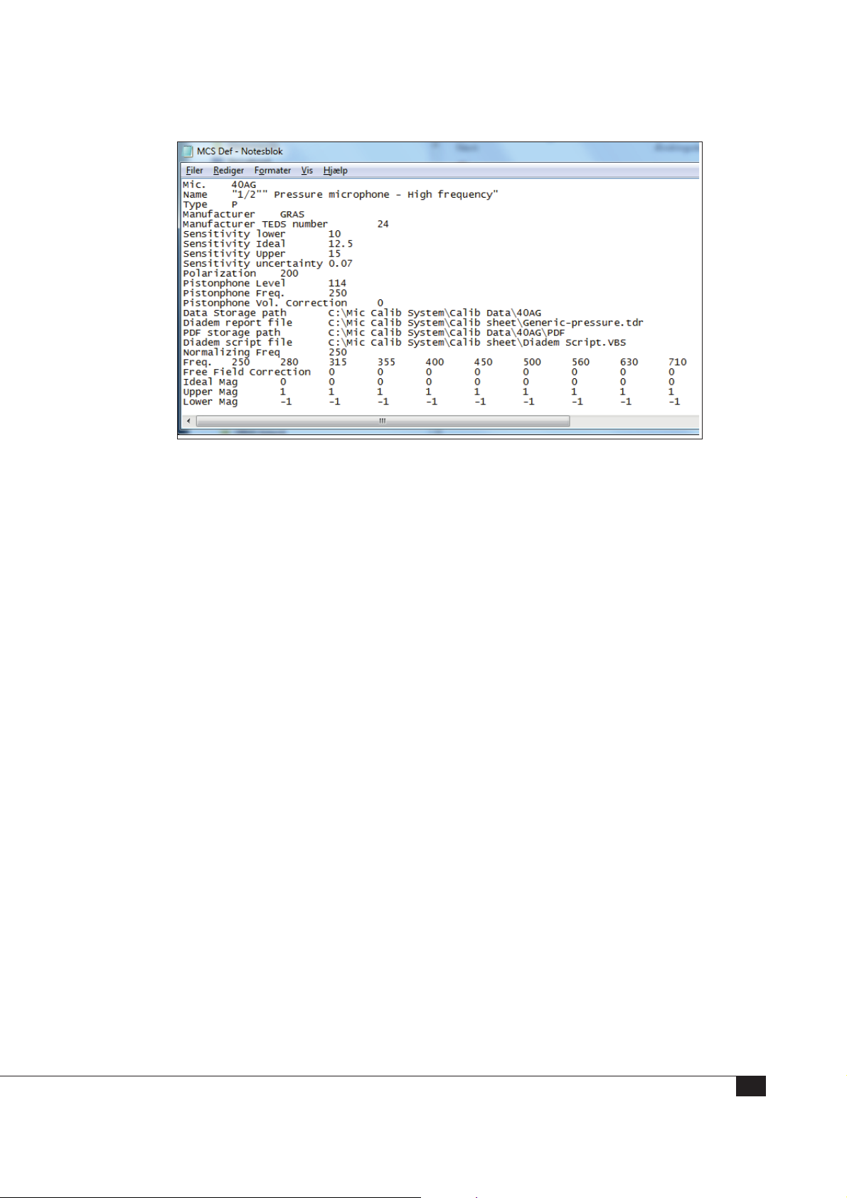
Fig. 14. The microphone definition file
This screenshot shows a section of a microphone definition file. The following two lists
explain the details of the files for microphones and for preamplifiers.
Data in the Microphone Definition List
Identify the microphone with
1. The microphone’s type number, such as 40AB, in Mic
2. Name of the microphone
3. Type, as in free field (F), pressure (P), random incidence (R), or other(O)
4. The name of the Manufacturer, such as G.R.A.S. Sound & Vibration
List the specifications
5. Sensitivity Lower – Lower limit of sensitivity
6. Sensitivity Ideal – Nominal value of sensitivity
7. Sensitivity Higher – Upper limit of sensitivity
8. Sensitivity Uncertainty – Absolute value of the sensitivity’s uncertainty
9. Polarization – Whether prepolarized (use 0 [V]) or externally polarized (use 200
[V])
10. Pistonphone Level – For example, enter 114 dB for the 42AP pistonphone
11. Pistonphone Frequency – For example, enter 250 Hz for the 42AP pistonphone
57
Page 58

12. Pistonphone Vol Correction – the pistonphone volume correction in dB for each
microphone type
13. Data Storage Path – Where the 90CA stores data
14. DIAdem report file – Location and file name of the DIAdem report template (.tdr)
15. PDF storage path – Where the 90CA stores the calibration files (as PDFs)
16. DIAdem script file – Location and file name of the DIAdem system file used for
printing out the calibration sheet
17. Normalized Freq. – Frequency to which the frequency response is normalized
18. Freq. – Frequencies for which the system calibrates the microphone
19. Free Field Correction – Free field corrections for this microphone type
20. Ideal Mag – Nominal pressure response [dB] normalized to the frequency stated in
line 17.
21. Upper Mag – Upper limit for frequency response in dB
22. Lower Mag – Lower limit for frequency response in dB
Data in the Preamplifier Definition List
Identify the preamplifier with
1. The preamplifier’s type number in Type
2. Name of the preamplifier
List the specifications
3. Data Storage Path – Where the 90CA stores data
4. Diadem report file – Location and file name of the DIAdem report template (.tdr)
5. PDF storage path – Where the 90CA stores the calibration files (as PDFs)
6. DIAdem script file – Location and file name of the DIAdem system file used for
printing out the calibration sheet
7. The name of the Manufacturer
8. Test SysCheck – Option to test SysCheck if included in preamplifier (Yes or No)
9. Test Insert Voltage – Option to test Insert Voltage if available (Yes or No)
58
Page 59

10. With TEDS – Yes, if the preamplifier is built with TEDS
11. DC Upper Limit – The maximum DC offset
12. DC Lower Limit – The minimum DC offset
13. Sensitivity Upper Limit – Upper level of sensitivity
14. Sensitivity Lower Limit – Lower level of sensitivity
15. Noise LIN, Max – Maximum level of LIN noise
16. Noise AW Max – Maximum level of AW noise
17. SysCheck Freq – Maximum level of AW noise
18. SysCheck Upper Limit – SysCheck upper level tolerance
19. SysCheck Lower Limit – SysCheck lower level tolerance
20. Insert Frequency – Insert test frequency
21. Insert Upper Limit – Upper level tolerance
22. Insert Lower Limit – Lower level tolerance
23. Normalized Freq. – Frequency to which the frequency response is normalized
24. IECP on/off – Indicate whether preamplifier is CCP type
25. Frequency – Frequencies for which the system calibrates the microphone
26. Ideal Mag – Nominal pressure response [dB] normalized to the frequency stated in
line 17.
27. Upper Mag – Upper limit for frequency response in dB
28. Lower Mag – Lower limit for frequency response in dB
Setup.txt: The Microphone Calibration System Setup File
When you start up the SW0002 Calibration Software for the 90CA, the software reads
the text file called setup.txt. Therefore, the location and contents of this file are critical.
Setup.txt must always be located in the same directory as your application file. Your
90CA system is delivered with the file located at
C:\Program Files\National Instruments\LabVIEW 8.2\setup.txt
To find the location of the default directory:
59
Page 60
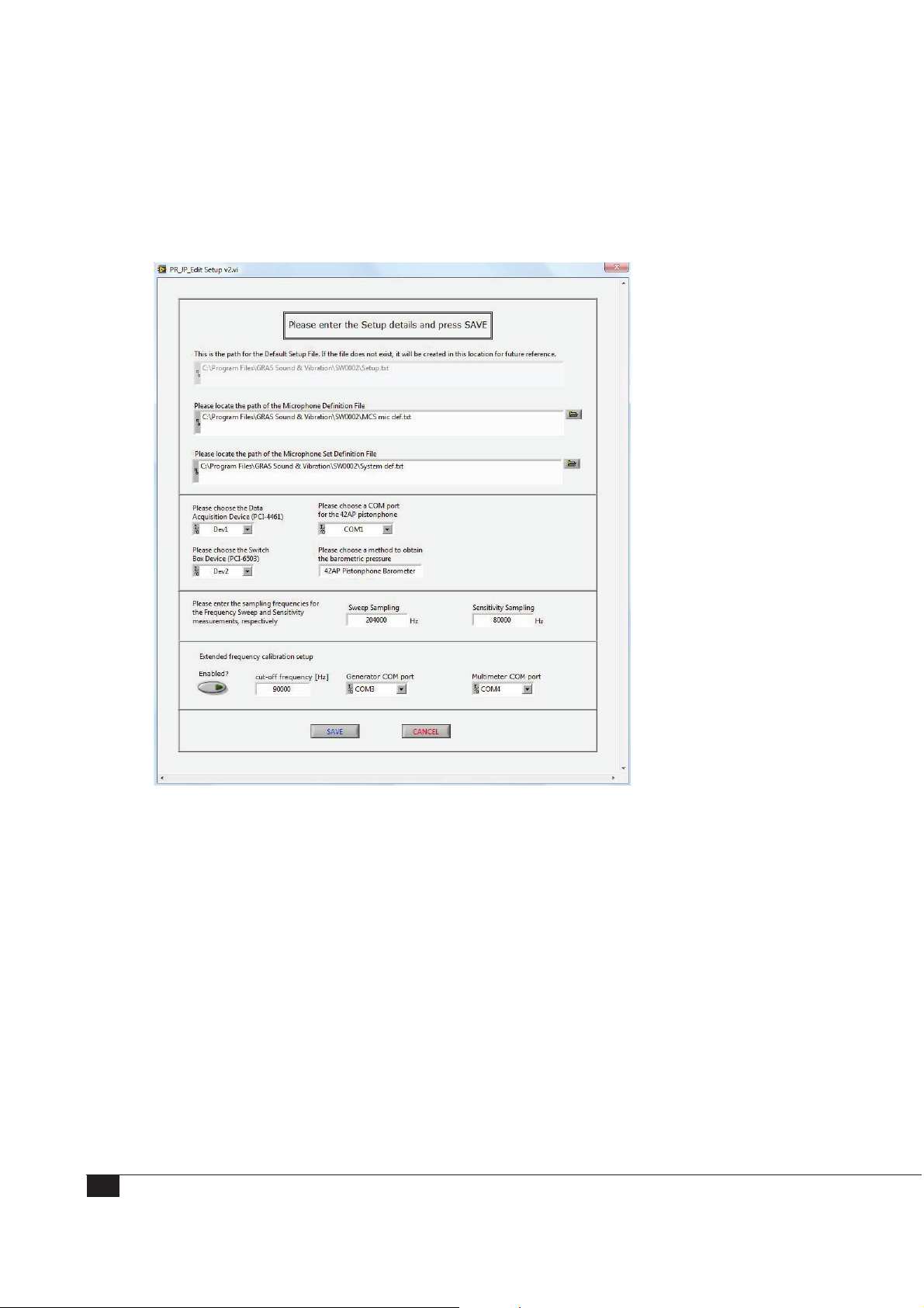
1. Start the Microphone Calibration System Software,
2. Navigate to the “Setup” Tab
3. The path is listed in the “Default Directory” field.
Fig. 15. The edit Setup window
If the file is deleted or moved from the default directory, the system will prompt for the
necessary information and create a new Setup.txt file.
Contents of Setup.txt
The Setup.txt contains:
• The locations of the Microphone Definition File and the Microphone Set
Definition File.
• DAQmx Device Name 4461 – Name of the Data Acquisition Board NI 4461 as
defined in the National Instruments Measurement and Automation Explorer.
• COM port for 42AP interface – The name of the COM port used for communicating with the 42AP pistonphone
60
Page 61

• DAQmx Device Name 6503 (6509 for PXI-based system) – The name of the
NI 6503 board (PXI: 6509) as defined in the National Instruments Measurement
and Automation Explorer
• Method to obtain the Barometric pressure
There are four different settings to choose between: “Type in Manually” where you
enter the barometric pressure manually, “42AP Pistonphone Barometer” where
the 42AP automatically provides the system with the pressure, and “DPI 141
Barometer” and “DPI 142 Barometer” where the barometric pressure is automatically given from the Drüg Barometer Type DPI 141 or DPI 142. Communication
with other types of barometers isn’t supported by the system.
• Sampling Rates – Typical 202 kHz for Sweep Sampling and 80 kHz for
Sensitivity Sampling.
• Extended Frequency Calibration Setup
Enabled: Select Enabled to configure the system for high frequency calibration.
Cut-off frequency: Enter the frequency where you want the system to switch to
the 33210A (35500B) generator and the 34465A multimeter.
Generator COM port – select the COM port used for the signal generator.
Multimeter COM port – select the COM port used for the multimeter.
• Additional COM port for external barometer
if DPI 141 or DP 142 has been selected in the “Method to obtain Barometric
Pressure” field, the name of the COM port used for communicating with the DPI
141 or DPI 142 barometer is shown.
Editing and Saving Setup.txt
Click Edit System Setup in the Setup Mode. A new window opens then and the new
setup parameters can be made.
In the Setup Mode, you can also view the Measurement setups for Sweep. All these
values are automatically reset when you exit the program. Therefore, if you need to save
changes to these values, you must do so before exiting the program.
61
Page 62
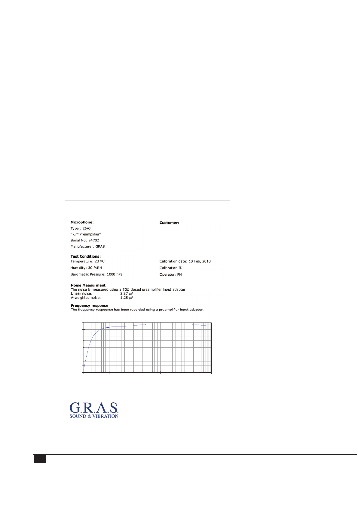
Editing the Calibration Charts in DIAdem
You can customize both the text and the design of the calibration charts. The three
report layout files are located in C:\Mic Calib System\Calib Sheet:
• generic-freefield.tdr for free-field microphones
• generic-pressure.tdr for pressure microphones
• generic-random.tdr for random microphones.
To edit the report files,
1. Open DIAdem and go to Navigator mode.
2. Open the report file in the DIAdem Report mode.
3. Click Print in the 90CA software program and the calibration data is transferred
to the DIAdem Data Portal. (The 90CA provides only the data listed in the Data
Portal.) The data from the Data Portal is inserted into the Calibration Certificate
with DIAdem expressions.
CERTIFICATE OF CALIBRATION
Page 1 of 2
62
-0.8
-0.9
-1
-1.1
-1.2
-1.3
-1.4
Frequency Response [dB]
-1.5
1 10 100 1000 10000 100000
Calibration Laboratory:
Calibration System made by G.R.A.S. Sound & Vibration, Denmark
G.R.A.S. Sound & Vibration
Skovlytoften 33
2840 Holte
Denmark
Phone: +45 45664046
Fig. 16. Calibration certificate, page 1
Freq [Hz]
Page 63
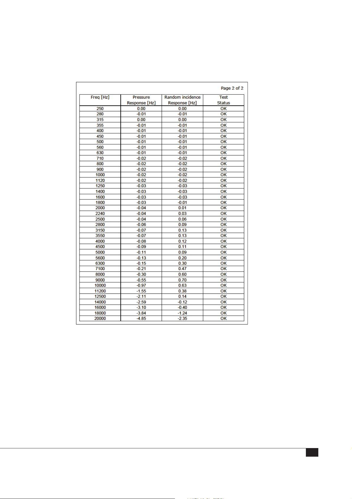
The calibration certificate is two pages. The first page displays the frequency response,
the second page contains all the data.
Fig. 17. Calibration certificate, page 2
For more information about the functions of DIAdem and the syntax of the DIAdem
expressions, see the Quick Tour in DIAdem Help.
63
Page 64

The File Structure on the System Controller
The location of all files is defined in the Microphone Definition File.
Folder Location What is Stored in this Folder
C:\Program Files\GRAS Sound &
Vibration\SW0002
C:\Mic Calib System\Calib Data When a calibration is completed, the calibration
C:\Mic Calib System\Calib Sheet This folder contains
The SW0002 License File
All definition files
data is saved in a text document that is placed in
this folder.
The calibration certificates in .pdf format are
placed in this folder.
• The DIAdem script file
• A template for a daily calibration report
• An Uncertainty Calculation document
The G.R.A.S. Sound & Vibration calibration software, SW0002, is license protected.
The license file, XLicense.txt, is generated by G.R.A.S. when the calibration software is
installed on the computer because it is locked to the hardware in the System Controller:
• Data Acquisition NI-card Type PCI-4461/PXI-4461
• Control Switch NI-card Type PCI-6503/PXI-6509
This means that the SW0002 software can only run on a system controller with the
two specific NI cards described in the license file. If one of the cards is broken, it cannot
be replaced with another card of same type and you will see a license error when the
software is running. Therefore, if you need to replace either of the NI cards, you will
need to request a new license file.
The license file must always be placed in the same directory as the SW0002
Microphone Calibration System program. If it is placed elsewhere, the software will
display a license error because it cannot find the file.
Note: Do not edit or modify the file in any way or the system will report an error. If the
file is modified or deleted, or you receive any errors, contact support at [email protected]
64
Page 65
Uncertainty Calculations
The Uncertainty Calculation spreadsheet lists the calculated system uncertainty for each
type of microphone and for the individual parameters such as
• Sensitivity
• Noise
• Polarization voltage
• Capacity
• Volume correction
• Pressure
• Humidity
• Temperature
This information can also be compared to the National Physical Laboratory uncertainty.
The following table lists the total uncertainty for each standard microphone. All the
uncertainties – the microphone sensitivity uncertainty, the calibration conditions, the AC
voltage uncertainty, and the pistonphone – are summed up in the right column.
Type no Mic Type Uncertainty (dB)
40AC WS2F 0.063
40AB WS2F 0.069
40AD WS2P 0.072
40AE WS2F 0.067
40AF WS2F 0.067
40AG WS2P 0.063
40AN WS2F 0.072
40AO LS2aP 0.063
40AP WS2P 0.069
40AQ W2SD 0.072
40AR W2SD 0.072
40AU LS2aP 0.063
40BD P 0.072
40BE WS3F 0.073
40BF F 0.073
40BH P 0.072
40BP P 0.072
40DP P 0.073
40EN WS1P 0.064
40EU LS1P 0.064
65
Page 66

Warranty and Maintenance
The 90CA is assembled and tested by G.R.A.S. before leaving the factory. An individual
test certificate is included with each 90CA.
Warranty
All G.R.A.S. products are made of high-quality materials that will ensure life-long stability and robustness. The 90CA is delivered with a 2-year warranty.
Damaged diaphragms in microphones can be replaced.
The warranty does not cover products that are damaged due to negligent use, an incorrect power supply, or an incorrect connection to the equipment.
Calibration
Before leaving the factory, all G.R.A.S. products are calibrated in a controlled laboratory
environment using traceable calibration equipment. We recommend a yearly recalibration
at minimum, depending on the use, measurement environment, and internal quality
control programs.
We recommend a daily check of the 90CA using the 40AG reference microphone to
ensure the validity of your calibrations. If you start each calibration session with a level
measurement of the 40AG you can verify that the system works properly.
Cleaning
Keep the system in a clean environment; keep the reference pistonphone and microphone in a safe and dry place when not in use.
Store the preamplifiers in a clean and dust-free environment.
Cover the terminal areas with their protection caps to prevent dust and tiny hairs from
entering the high-impedant connector area.
Grids and windscreens make an adequate protection, reducing any need to clean
microphones.
Avoid touching the diaphragm on any microphone during general use. Never touch the
surface with anything that has a point such as a pencil or finger.
If something is spilled on the diaphragm, such as oil, use a clean cloth or cotton ball
dipped in alcohol or benzine (for oils) to wipe the surface, using even pressure at all
times. Use cleaning solutions that are appropriate, for example, benzine, alcohol, and so
on.
66
Page 67

The diaphragm is a 2-micron thick metal foil, so any fluid that doesn’t damage stainless
steel can be used. Be very careful during cleaning because the diaphragm is extra fragile
in that situation.
Sometimes you cannot see that the diaphragm is dirty. It is only when connected to the
electrostatic actuator that you can measure that something is disturbing the vibration.
That happens when the mass of the foreign substance is greater than the mass of the
diaphragm.
Before calibrating, always make sure the microphone connector is clean and that no dust
is viewable in the connector of the preamplifier. If you see dust, use dry air to blow it
away.
How to clean a microphone membrane
• Very gently
• Use alcohol and a cotton ball
• After cleaning, wait an hour before calibration
• Use a mix of water and a little dishwater if the microphone is very dirty
How to clean the gold connector
• Use a very soft foam brush
• Use compressed air
Service and Repairs
All repairs are made at G.R.A.S. International Support Center located in Denmark. Our
Support Center is equipped with the newest test equipment and staffed with dedicated
and highly skilled engineers. Upon request, we make cost estimates based on fixed
repair categories.
If a product covered by warranty is sent for service, it is repaired free of charge, unless
the damage is the result of negligent use or other violations of the warranty. All repairs
are delivered with a service report, as well as an updated calibration chart.
Manufactured to conform with:
CE marking directive:
93/68/EEC
WEEE directive:
2002/96/EC
RoHS directive:
2002/95/EC
G.R.A.S. Sound & Vibration continually strives to improve the quality of our products for our customers; therefore, the
specifications and accessories are subject to change.
67
 Loading...