

G.R.A.S. 90AA, 90AB Instruction Manual
www.gras.dk
LI0039 – 5 July 2017
Instruction Manual
G.R.A.S. Audiometer Calibration Systems 90AA/90AB

2
LI0039 – 5 July 2017
Revision History
Any feedback or questions about this document are welcome at gras@gras.dk.
Revision Date Description
1 19 December 2011 First publication
2 5 July 2017 42AG substituted for the obsolete 42AB
Copyright Notice
© 2011-17 G.R.A.S. Sound & Vibration A/S
http://www.gras.dk
Any technical documentation that is made available by G.R.A.S. is the copyrighted work of
G.R.A.S. and is owned by G.R.A.S.
The content in this document is subject to change without notice. G.R.A.S. Sound & Vibration A/S
is not liable or responsible for any errors or inaccuracies that may appear in this document.
Trademarks
Product names mentioned in this document may be trademarks or registered trademarks of their
respective companies and are hereby acknowledged.
3
LI0039 – 5 July 2017
Contents
Introduction .................................................................................. 5
Getting Started with the 90AA and 90AB .......................................... 7
Using this manual .......................................................................... 8
General tips for using the HW1001 ............................................................. 9
Calibrating the HW1001 Audiometer Analyzer ................................. 10
When to calibrate ..................................................................................... 10
Adjusting the scale settings ....................................................................... 10
Carrying out the calibration ........................................................................ 10
dB Value ................................................................................................. 11
Calibrating HDA-200 Circumaural Earphones .................................... 12
Setting up a high-frequency coupler calibration ............................................ 12
Calibrating the spring load for 43AA ........................................................... 12
Calibrating the sensitivity of 43AA ............................................................. 13
Calibrating the microphone on the jig .......................................................... 13
Measuring the audiometer with earphones .................................................. 13
Calibrating TDH-39 Supra-Aural Earphones ...................................... 15
Setting up a 6cc coupler calibration ............................................................ 15
Calibrating the spring load for 43AF ........................................................... 15
Calibrating the sensitivity of 43AF.............................................................. 16
Calibrating the microphone on the jig .......................................................... 16
Measuring the audiometer ........................................................................ 16
Calibrating Insert Earphones .......................................................... 18
Calibrating the EAR 3A ear-insert .............................................................. 18
Mounting the RA0113 in 43AF ................................................................. 18
Calibrating the sensitivity of 43AF.............................................................. 18
Calibrating the microphone on the jig .......................................................... 19
Measuring the audiometer ........................................................................ 19

4
LI0039 – 5 July 2017
Memory handling ........................................................................ 20
Memory structure .................................................................................... 20
SD-card memory...................................................................................... 20
Select the device for storing ...................................................................... 21
Storing a measurement setup .................................................................... 21
Retrieving stored setups and data .............................................................. 23
Deleting files and folders in the memory ..................................................... 23
Technical Specifications ................................................................ 25
Standards ............................................................................................... 25
AC-out .................................................................................................... 30
Ordering Information .................................................................... 32
Options and Accessories ........................................................................... 32
Calibration ............................................................................................... 32
Warranty ................................................................................................. 33
Service and Repairs .................................................................................. 33

5
LI0039 – 5 July 2017
Introduction
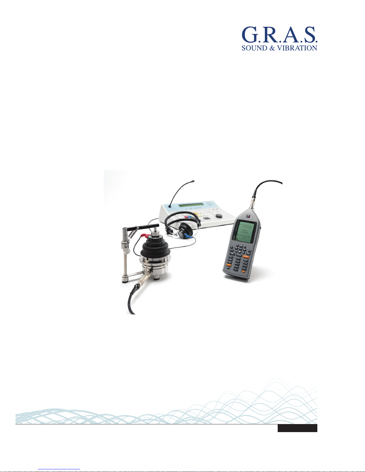
This manual contains information about operating and calibrating the components of the
90AA and the 90AB. Due to their similarities, both products are described in this one
manual.
Both systems include the Audiometer System Calibrator HW1001. This portable system
makes acoustical measurements of frequency and levels of the test signal, as well as
harmonic distortion. The result table includes values for frequency of the test tone, level
of the test tone, LZeq, and harmonic distortion. These values are displayed together
with the 1/3 octave band spectrum.
The 90AA and 90AB Audiometer Calibration Systems comply with the following international standards:
• IEC 60318 Electroacoustics – Simulators of human head and ear - Part 1: Ear
simulator for the calibration of supra-aural earphones, 1998-07.
• ITU-T Recommendations P.57 (08/96) Series P: Telephone transmission quality,
Objective measuring apparatus: Artificial ears.
• ANSI S 3.7 – 1995 – American National Standard for Testing Earphones
The audiometers are calibrated with their supra-aural earphones, circumaural earphones,
and insert earphones. This is done with the couplers provided with the 90AA and 90AB.
• The supra-aural earphones TDH 39 and TDH 49 are standardized earphones
that require calibration with a 6cc coupler. These are also known as audiometric
earphones, headphones, headsets.
• The circumaural earphones HDA-200 are a standardized earphone that must be
calibrated with an ear simulator based on the IEC 60318 standard. HDA-200 is
also known as a high-frequency earphones, headphones, or headsets.
• Insert earphones, also known as ear inserts, are 3A and 5A. These are de-facto
standardized earphones, which can be calibrated with a 2cc coupler.
A typical calibration interval is once every other year. The calibration checks at each
frequency for distortion and calibrates the level.
The high-frequency coupler setup (43AA) has a test jig and an ear simulator (RA0039)
that is designed to follow the specifications of the IEC 60318-1 standard. The acoustic
input impedance of the RA0039 ear simulator closely resembles that of the human
ear. Therefore, it “hears”, or loads a sound source, in the same way as the human ear.
The adjustable spring-loaded arm of the test jig lets you carry out measurements under
well-defined conditions.

6
LI0039 – 5 July 2017
The 6cc coupler setup (43AF) has a test jig and an ear simulator (RA0075) that is
designed to follow the specifications of the IEC 60318-1 standard. The RA0075 is
designed with a volume of 5.6 cm3, which approximates the volume of 6 cm3 when a
human ear is wearing a supra-aural earphone. This is why this setup is ideal for measuring the earphones of audiometers. The adjustable spring-loaded arm of the test jig lets
you carry out measurements under well-defined conditions.
7
LI0039 – 5 July 2017
Getting Started with the 90AA and 90AB
Before you begin using your G.R.A.S. Audiometer Calibration System, use these lists to
check that you have the following components.
The 90AA packing list
Included Items Part Number
Ear Simulator Kit according to IEC 60318-1 & -2 43AA *
1" 6cc Coupler Kit according to IEC 60318-3 43AF *
1 m LEMO-LEMO extension cable
Audiometer calibration analyzer HW1001
Multifunction Sound Calibrator 42AG
Force cauge RA0184
Lightweight suitcase
Manual LI0039
* The artificial ears are delivered with the 26AB ¼” preamplifiers with LEMO
connectors.
The 90AB packing list
Included Items Part Number
Ear Simulator Kit according to IEC 60318-1 & -2 43AA *
6cc NBS 9A Coupler according to ANSI S3.7-1995 RA0075
Thread adapter for NBS 9-A coupler RA0076
1” pressure microphone 40EN
1 m LEMO-LEMO extension cable
Audiometer calibration analyzer HW1001
Manual LI0039
* The artificial ears are delivered with the 26AB ¼” preamplifiers with LEMO
connectors.
8
LI0039 – 5 July 2017
Using this manual
The following conventions are used in this manual.
Menu navigation
For the HW1001 Audiometer Calibration Analyzer, the menu navigation is described by
each of the menus you must go through. For example,
SETUP > 1 (Instrum.) > 1 (Storing)
means press the SETUP button, then 1 on the number pad to choose the first item on
the menu, and then 1 on the number pad to choose the first item on the new menu.
Field navigation
To navigate between editable parameter fields in the menu, use the cursor or arrow
keys. A selected and editable field is shown in inverted colors, that is, white text on
black background.
Key or button identification
References to keys on the HW1001 keypad are written in uppercase, for example, INC
(increase) and DEC (decrease).
SETUP START
LIGHT
4
PRINT
CAL
.
1
TBL
EXIT
5
NETW
BATT
0
Σ↔Δ
6
2
f↔t
ABS t
±
FUNC
3
DEC
RECALL
DEL
INC
ENTER
PAUSE
CONT
STOP
7
MODE
8
TC
9
A-prew
STORE
RECORD
M3
M4
M2
M1
PQRS
GHI
TUV
JKL
ABC
WXYZ
MNO
DEF
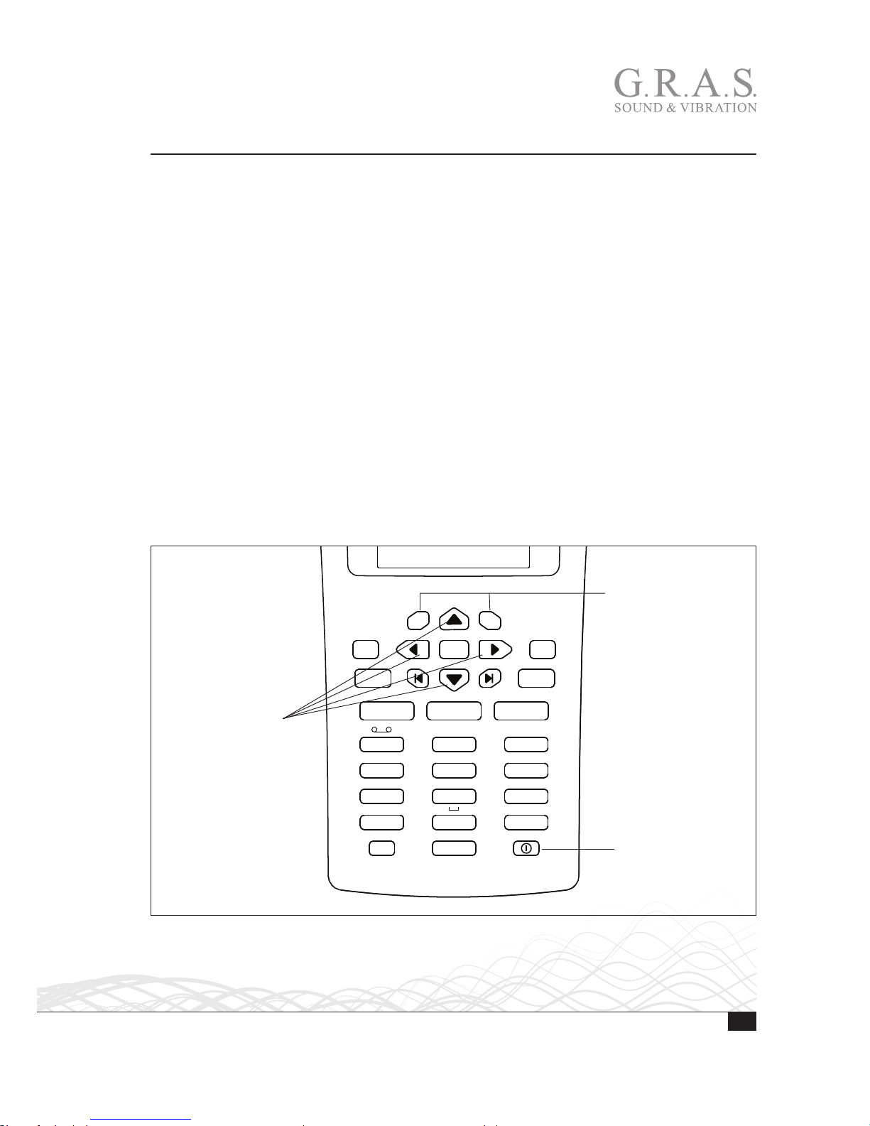
The INC and DEC
buttons
Power on and off
The four arrow or
cursor buttons
Fig. 1. The keypad on the HW1001 with several highlights.

9
LI0039 – 5 July 2017
General tips for using the HW1001
Use the INC and DEC keys to increase or decrease the current setting of the parameter.
Alternatively use the keypad to type in the required value, whenever applicable.
When the # sign appears in the lower line of the display, you can type in data.
If you use the number keypad, press ENTER before moving to the next field. This is not
necessary when using the INC and DEC keys. E is shown on lower line as a prompt.
To leave a menu and put your changes into effect, press ENTER.
There is no cancel function available, so you must complete your action. Reenter if you
make a mistake.
Press STOP when you want to terminate an ongoing measurement.

10
LI0039 – 5 July 2017
Calibrating the HW1001 Audiometer Analyzer
Calibration is done through the menus and buttons on the HW1001. No special tools
are required.
When to calibrate
Calibration of the HW1001 should take place before a measurement session begins, or
when required by the standards in use.
Note: This step does not replace calibration with a sound calibrator because the
sensitivity adjustment procedure will be unable to reveal possible microphone,
preamplifier, or extension cable malfunctions.
Adjusting the scale settings
The HW1001 has a 120 dB dynamic range (10–130 dB SPL), so the 80 dB bar graph
range is only a display limitation. There is no need to set the full scale before going to
the calibration menu. Also, because the HW1001 automatically enters C-weighted
mode, you do not need to enter the calibrator frequency.
However, you may have to adjust the display top scale setting to see the top of the
bar graph. Use the INC and DEC keys to make these adjustments before you go to the
calibration menu.
Carrying out the calibration
Use the 42AG for calibration.
1. Mount the calibrator onto the HW1001. Switch on the sound calibrator and wait until
the level has stabilized. For information about the time required for stabilization, see
the 42AG instruction manual.
2. Press CAL to go to the Calibration menu.
Note: Never calibrate the instrument until at least three minutes after turning on the
instrument.
3. The default output level of the 42AG is 114 dB. Knowing that value means you will
know what level the measuring instrument is supposed to show. The output level is
printed on the sound calibrator as well as in the documentation.
4. Free-field microphones require lower settings. Note that instruments using free-field
microphones must be adjusted to a value slightly lower than the output level of the
sound calibrator. For a half-inch cartridge, this typically amounts to 0.2 dB lower for
calibrators producing a 1000 Hz calibration signal. This means the HW1001 should
be set to 113.8 dB when using the 114 dB @ 1000 Hz 42AG sound calibrator.
 Loading...