

Page 1
Instruction Manual
Outdoor Microphone System Types 41AM / 41CN
Skovlytoften 33, 2840 Holte, Denmark
www.gras.dk gras@gras.dk
SOUND & VIBRATION
G R A S
...
.
Page 2

Revision 11 June 2010
LI0002
Outdoor Microphone System
Types 41AM / 41CN
Note: unless individually specied, the term “Outdoor Microphone
System” throughout this document refers to both types, i.e.
Type 41AM and Type 41CN.
Page 3

Important! any dismantling details given in this document are
addressed solely to qualied service personnel who must ensure
that the unit is rst disconnected from its power supply before pro-
ceeding.
Page 4

CONTENTS
1. Introduction and Description. . . . . . . . . . . . . . . . . . . . . . . . . . . . . . . . . . . . . . . 5
1.1 Available Types and Applications ......................................6
2. Main Components ................................................7
2.1 Windscreen . . . . . . . . . . . . . . . . . . . . . . . . . . . . . . . . . . . . . . . . . . . . . . . . . . . . . . . 9
2.2 Microphone Assembly. . . . . . . . . . . . . . . . . . . . . . . . . . . . . . . . . . . . . . . . . . . . . . . 9
2.2.1 Pressure Equalisation ................................................10
2.2.2 Electrostatic Actuator .................................................10
2.2.3 Microphone ........................................................10
2.2.4 Dismantling the Microphone Assembly ...................................11
3. Access to Electronics Assembly ...................................12
4. Calibration . . . . . . . . . . . . . . . . . . . . . . . . . . . . . . . . . . . . . . . . . . . . . . . . . . . . . 14
4.1 Electrostatic Actuator ..............................................14
4.1.1 Adjustment .........................................................14
4.1.2 Calibration Control Box AC0001 ........................................14
4.2 Pistonphone .....................................................15
4.2.1 Setup and adjustment ................................................16
4.3 Factory Calibration ................................................16
5. Maintenance ...................................................17
5.1 Windscreen . . . . . . . . . . . . . . . . . . . . . . . . . . . . . . . . . . . . . . . . . . . . . . . . . . . . . . 17
5.2 Dehumidiers ....................................................17
5.3 Multi-frequency Calibration Check (Optional) . . . . . . . . . . . . . . . . . . . . . . . . . . . . 18
5.3.1 Output Connections . . . . . . . . . . . . . . . . . . . . . . . . . . . . . . . . . . . . . . . . . . . . . . . . . . 18
6. Service and Repair ..............................................19
7. Specications ..................................................20
8. Circuit and Component Diagrams. . . . . . . . . . . . . . . . . . . . . . . . . . . . . . . . . . 22
Page 5
Outdoor Microphone System - Page 5
G.R.A.S. Sound & Vibration
1. Introduction and Description
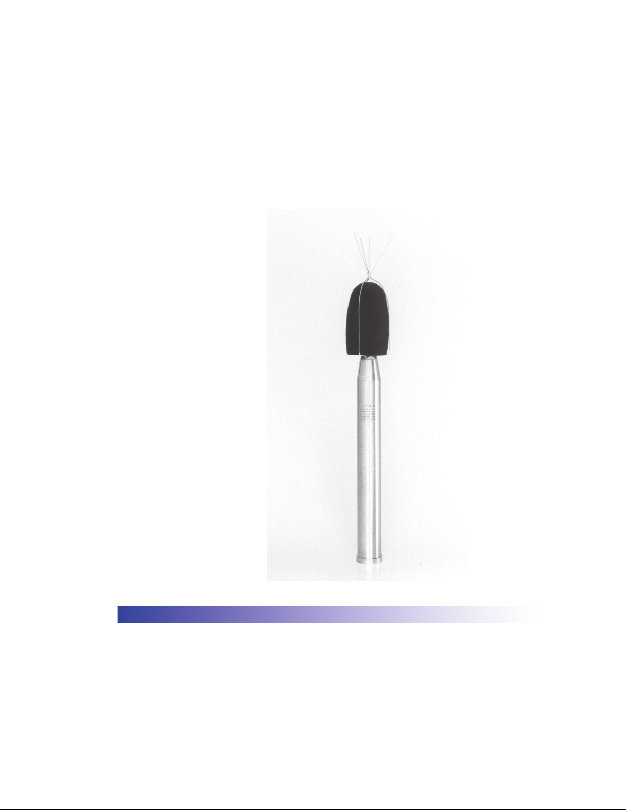
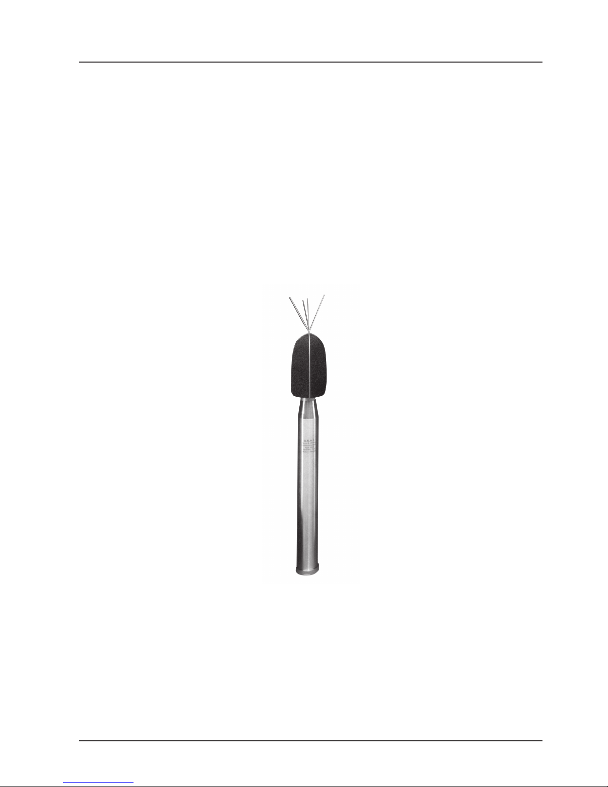
The G.R.A.S. Outdoor Microphone System (Fig. 1.1) is for outdoor use whenever trouble-free
noise monitoring is required, e.g. around airports or in communities.
It complies with IEC 651 Type 1 and ANSI S1.4 1983 Type 1 requirements and can be used with
any suitable electronic sound or vibration measurement system. It is PTB approved as part of
an IEC 651 Type 1 system.
A ½-inch precision condenser microphone and thick-lm preamplier ensure maximum stability
and performance. Both microphone and casing are made of stainless steel.
Precise in-situ calibration checks at 1000 Hz are enabled any time via a built-in electrostatic
actuator and test oscillator.
Fig. 1.1 Outdoor Microphone System
Page 6
Outdoor Microphone System - Page 6
G.R.A.S. Sound & Vibration
Fig. 1.2 Outdoor Microphone System. Types, reference
directions and applications
1.1 Available Types and Applications
There are two types of the Outdoor Microphone System, these are Type 41AM and Type 41CN.
Each has its own measurement reference direction and application, i.e.:
Type 41AM
Measurement reference direction - vertical (along axis of symmetry)
Angle of incidence - 0°
Application - monitoring airport noise
Type 41CN
Measurement reference direction - horizontal (perpendicular to axis of symmetry)
Angle of incidence - 90°
Application - monitoring community noise
See also Fig. 1.2.
Both types are almost physically identical; differing only in the type of the microphone cartridge
and rain-protection cap used. Type 41AM uses Microphone Cartridge Type 41AS and Type
41CN uses Microphone Cartridge Type 40AS.
Reference Direction
0° incidence (airport noise)
Type 41AM
Reference Direction
90° incidence (community noise)
Type 41CN
Page 7

Outdoor Microphone System - Page 7
G.R.A.S. Sound & Vibration
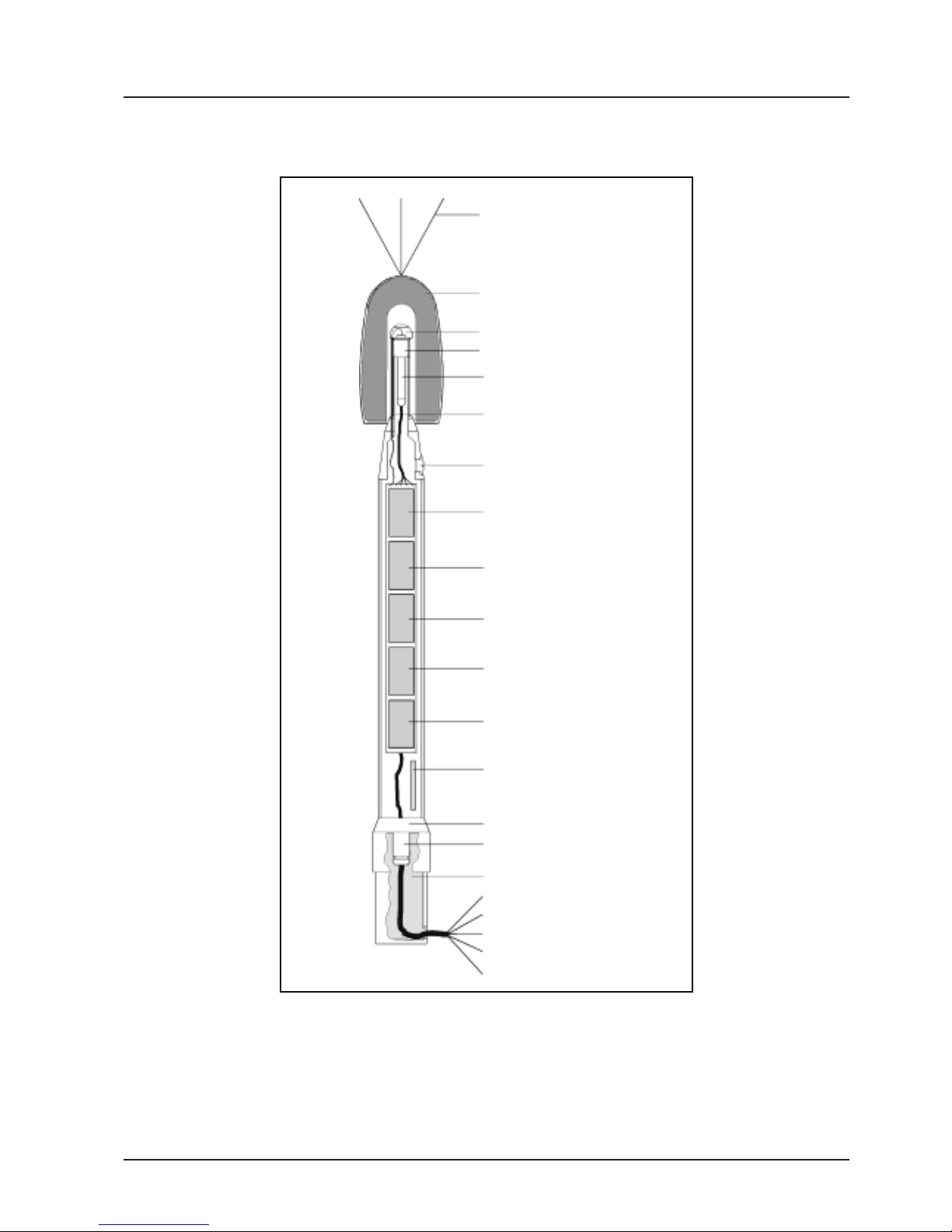
2. Main Components
The following is a brief description of the main components of the Outdoor Microphone System
(see also Fig. 2.1).
All external metal parts are made of stainless steel.
Windscreen and windscreen holder with anti-bird spikes.
Electrostatic actuator housing mounted on top of the condenser microphone.
Condenser microphone and preamplier mounted on top of the casing. The microphone
and electrostatic-actuator assembly are galvanically isolated from the system casing.
The top of the casing has an inspection window for viewing the state of the dehumidier
when the cover screw is removed.
The cylindrical casing contains the assembly of electronics and desiccator bags for absorb-
ing moisture.
The electronics include:
A switch-mode power supply for generating:
a) 200 V for microphone polarisation
b) 120 V for the microphone preamplier
And:
c) an A-weighting network
d) a circuit jumper for applying a gain of ± 20 dB to the microphone signal
A pole adaptor with a standard ISO 228/1 G 1½-in thread. Also used for the tripod adaptor
(Fig. 2.2).
The Outdoor Microphone System can be mounted on the tripod adaptor using the pole
adaptor. The cable and plug are readily led through the tripod adaptor. The tripod adaptor
is not meant for permanent outdoor installations, but for test setups in labs and short-term
outdoor surveys.
The connector is a 6-pole LEMO FFA.2S.306, which locks into a socket at the bottom of
the Outdoor Microphone System. It cannot be pulled out by its cable. It can be removed
only by pulling outwards on the knurled outer sleeve.
Page 8
Outdoor Microphone System - Page 8
G.R.A.S. Sound & Vibration
Fig. 2.1 Main components of the Outdoor Microphone
System
Anti-birds spikes
Windscreen and holder
Electrostatic actuator
½″ microphone
Preamplier
Equalisation vent
Calibration oscillator
Dehumidier inspection window
Lin. or A-weighting
Sensitivity control
0 or ±20 dB gain
Cable driver
DC - DC converter
Dehumidier
Pole adapter
LEMO connectror
12 - 18 V DC
Signal out
Test-oscillator start
Ground
Multi-freq. cal. check (optional)
Tripod adapter
Page 9

Outdoor Microphone System - Page 9
G.R.A.S. Sound & Vibration
Fig. 2.2 Left to right; tripod and pole adapters
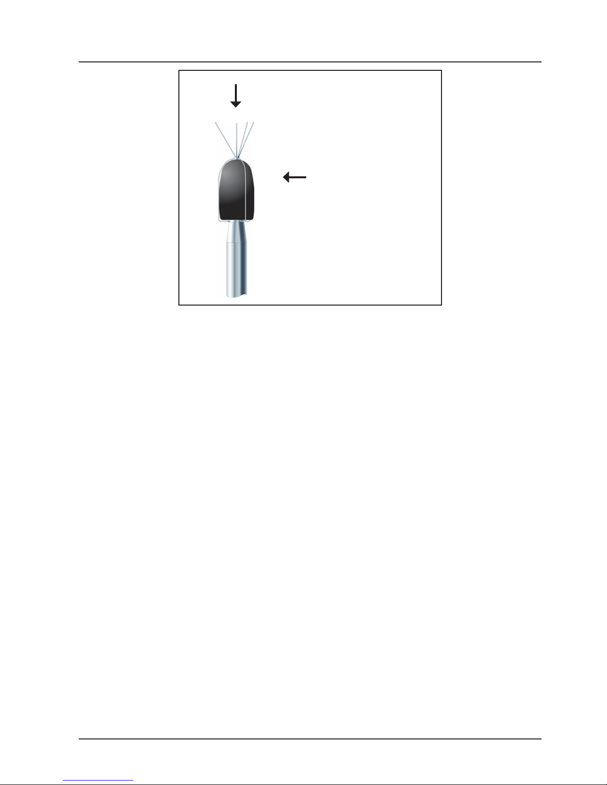
2.1 Windscreen
This comprises a windscreen and a windscreen holder (see Fig. 2.3).
The windscreen itself is made of polyurethane foam. It reduces wind-noise to a minimum and
gives maximum rain protection. It also allows for 0 ° (Type 41AM) and 90 ° (Type 41CN) refer-
ence directions of incidence.
The windscreen holder has four anti-bird spikes to prevent birds from perching on top of the
windscreen. The centre spike prevents smaller birds from perching between the other three
spikes.
Fig. 2.3 Windscreen of the Outdoor Microphone System
2.2 Microphone Assembly
On delivery, the microphone assembly is protected by a transport tube, see Fig. 2.4. A small
hole of 0.5 mm diameter at the top end of the transport tube ensures pressure equalization
during transport. The transport tube is also used when testing for self-noise. In this case, the
hole must be sealed using a piece of tape. Remember to remove the tape after use.
When screwing the windscreen onto the microphone, apply some silicone grease (supplied) to
the thread - see Fig. 2.4). The silicone grease is waterproof and protects against rust.
Anti-birds spikes
Windscreen
Windscreen holder
Page 10

Outdoor Microphone System - Page 10
G.R.A.S. Sound & Vibration
2.2.1 Pressure Equalisation
The pressure equalisation system, which ensures that the air-pressure within the cartridge of
the condenser microphone is kept equal to the ambient atmospheric pressure, allows sufciently
rapid pressure equalisation while keeping to a minimum the exchange of air between the interior
and exterior. This also extends the working life of the dehumidier.
Pressure equalisation takes place via the 1.5 mm diameter stainless-steel tube visible on the
side of the upper cylindrical section (see Fig. 2.4). This tube is also a conduit for the signal wire
connecting the calibration oscillator with the electrostatic actuator.
2.2.2 Electrostatic Actuator
The position of the actuator relative to the microphone is maintained by a calibration ring positioned under the Teon sleeve. The calibration ring ensures the correct spacing between the
actuator and the diaphragm of the microphone.
For inspection purposes, access to the signal wire in the pressure-equalisation tube is gained
after removing the rain-protection cap (see section 2.2.4) which is held in place by a left-hand
thread mushroom-head screw. In the case of the Type 41CN, the small black plastic cone
mounted on top of the screw has to be removed rst.
2.2.3 Microphone
If the electrostatic actuator, Teon sleeve and calibration ring are removed, the microphone
can be unscrewed (see section 2.2.4). The microphone is mounted on a galvanically isolated
assembly, together with a thick-lm, high-impedance input preamplier which is miniature,
ceramic-based, and robust.
Fig. 2.4 Showing microphone assembly - note the difference between
the two rain-protection caps
Rain-protection cap and actuator
Teon sleeve
Pressure-equalisation tube
Dehumidier inspection window
Transport tube
Type 41AM
Type 41CN
Add silicone grease to this thread
Page 11

Outdoor Microphone System - Page 11
G.R.A.S. Sound & Vibration
2.2.4 Dismantling the Microphone Assembly
Dismantling the microphone assembly is rarely necessary and should be done by a qualied
technician recognised by G.R.A.S. Sound & Vibration.
First disconnect the power from the Outdoor Microphone System before proceeding. The actua-
tor voltage is 300 V.
The circled numbers refer to which part of the special tool AM0038 (Fig. 2.5) to use
1. Unscrew the windscreen
1
.
2. Remove the black cone from the top of the rain-protection cap (Type 41CN only).
3. Unscrew the mushroom-head screw holding the Teon rain-protection cap in place.
Use
2
for the Type 41AM and 3 for the Type 41CN.
Note: Left-hand thread - unscrew clockwise.
4. Remove the Teon rain-protection cap.
5. Disconnect the signal wire (with gold plated pin) from the top of the actuator housing so
that it sticks directly out of the pressure-equalisation tube.
6. Use the special key RA0087 (Fig. 2.5) to unscrew the actuator housing (right-hand thread)
and remove the spacer and insulator rings placed around the microphone capsule. Be very
careful not to damage the diaphragm of the microphone capsule.
7. The microphone capsule can now be unscrewed to gain access to the preamplier. It is
recommended to mount a protection grid (not included) on the microphone capsule before
unscrewing it.
Re-assembling is in the reverse order of the above. Don’t forget the spacer and insulator rings
otherwise the microphone diaphragm can be seriously damaged.
After re-assemby, re-calibrate the electrostatic actuator as described in section 4.1.1.
Fig. 2.5 Special tools for dismantling the Outdoor
Microphone System; left to right:
Multi-spanner
Key for dismantling actuator housing
AM0038
RA0087 (not included)
1 2
3
5
4
Page 12

Outdoor Microphone System - Page 12
G.R.A.S. Sound & Vibration
3. Access to Electronics Assembly
For access to the electronics assembly, do the following. The circled numbers refer to which part of the tool
AM0038 (Fig. 2.5) to use:
1. Unscrew the large retaining ring at the base of the
casing
4
.
Make sure that only the retaining ring turns.
4. Remove the rubber O-ring, locking washer and
nut from the LEMO socket.
This will allow the silica-gel container to pass over
the LEMO socket.
2. Pull out the socket plate.
If necessary, insert the LEMO connector in the
LEMO socket and pull out the socket plate. This
will reveal the silica-gel container.
3. Unscrew the LEMO socket nut and remove the
socket plate
5
.
Note: steps 4 and 5 are necessary only if the silica-gel
container is to be removed. Otherwise, go to step 6 if
only access to the electronics is required.
Retaining ring
Silica gell
container
Socket plate
LEMO socket
LEMO socket
nut
LEMO socket
nut
Socket plate
Nut
Washer
O-ring
LEMO socket
NutWasherO-ring
LEMO socket
Silica-gel
container
Electronic
assembly
Socket plate
1
2
3
4
Page 13

Outdoor Microphone System - Page 13
G.R.A.S. Sound & Vibration
5. Remove the silica-gel container.
At this point, the silica-gel crystals can be
removed from the container, dried off and used
again (see section 5.2).
6. Unscrew the stainless-steel casing to give access
to the electronics assembly.
If necessary, remove the screw from the dehumidier inspection window and screw the tommy
bar (AM0063) in its place if the casing is difcult
to unscrew.
Dehumidier
container
Stainless-steel casing
Electronics assembly
5
6
Page 14

Outdoor Microphone System - Page 14
G.R.A.S. Sound & Vibration
4. Calibration
4.1 Electrostatic Actuator
The Outdoor Microphone System is equipped with a built-in electrostatic actuator to enable
rapid calibration checks in-situ. The electrostatic actuator is factory adjusted to simulate a sound
level of 90 dB at a frequency of 1000 Hz on the diaphragm of the microphone (94 dB is also
available on order). The electrostatic actuator is switched on by connecting pin 1 to pin 6 on the
LEMO socket (see Fig. 5.2). This will cause a calibration signal of 500 Hz AC to be applied to
the actuator.
Warning! do not touch the actuator while the calibration signal is applied. The voltage applied
to the actuator is approximately 300 V RMS. Extreme care should be taken when handling the
circuit boards while the power is on. High voltages are present!
The 500 Hz signal creates an oscillating electrostatic eld which causes the diaphragm of the
microphone to oscillate at twice the applied frequency thus generating a reference signal of
1000 Hz. The result is a simulated sound pressure on the diaphragm of the microphone which is
directly proportional to the applied voltage and inversely proportional to the spacing between the
actuator surface and the microphone diaphragm.
It can be shown that this method of calibration relates directly to simple absolute physical
parameters.
The stability of this method ensures that the microphone calibration is consistent; therefore no
other calibration check is necessary. Electrostatic actuator calibration should be carried out at
regular intervals.
4.1.1 Adjustment
With the electrostatic actuator switched on, adjust P201 (see Fig. 8.3) to give a signal output
level of 31.6 mV.
An electrostatic-actuator calibration is referred to a Pistonphone calibration as described in section 4.2.1 and assumes that the Outdoor Microphone System has a sensitivity of 50 mV/Pa. In
turn, this means that an output level of 31.6 mV will correspond with 90 dB as simulated by the
electrostatic actuator.
A-Weighting
At this stage, the A-weighting network can also be checked as follows:
1. Move the “Jumper for response” (see Fig. 8.3) from Lin to A-w.
2. With the electrostatic actuator switched on, adjust P101 (see Fig. 8.3) to give a signal
output level which corresponds with 90 dB, i.e. 31.6 mV.
3. Move the “Jumper for response” back to the position Lin.
Position Com is not used.
4.1.2 Calibration Control Box AC0001
A useful accessory available from G.R.A.S. is the Calibration Control Box AC0001 (see
Fig. 4.1). This has a lead which plugs directly into the output socket of the Outdoor Microphone
System. The AC0001 has sockets for signal output, remote-control calibration and external
power (12 – 18 V DC, e.g. from a G.R.A.S. Mains/line Adapter AB0002/AB0003*). It also has an
on/off switch for local calibration control.
* AB0002 for 230 V AC; AB0003 for 120 V AC
Page 15

Outdoor Microphone System - Page 15
G.R.A.S. Sound & Vibration
4.2 Pistonphone
If actuator calibration results give rise to suspicion by showing abnormal variations, i.e. in
excess of 0.4 dB (temperature coefcient accounted for), after a warm-up period of at least one
hour, a Pistonphone calibration is advisable.
A calibration using a Pistonphone (or Sound Calibrator) requires rst removing the windscreen
from the Outdoor Microphone System and mounting a special adapter in its place: no other
parts need be removed.
Use Adapter RA0009
1
for Type 41AM
Use Adapter RA0041
1
for Type 41CN
Note: remove the black plastic cone from the rain-protection cap only if a Sound Calibrator
is to be used.
The RA0009/RA0041 consists of a support tube with a close-tting collar which holds together
the two halves of a split coupler. The two halves of the split coupler are engraved with a
common number to show that they are correctly matched. The correction values supplied with
each RA0009/RA0041 must be applied to the nominal value for the Pistonphone or Sound Calibrator used (+ means add, – means subtract).
When using a Pistonphone, apply any barometric correction in the normal way. The Pistonphone/Calibrator must be tted with a coupler for 1-inch microphones.
Once the windscreen has been removed, mount the adapter as follows (refer to Fig. 4.2):
Fig. 4.2 Mounting the Adapter RA0009/RA0041
1
The Adapter RA0009/RA0041 is not included with the Outdoor Microphone System Type 41AM/41CN but is available on sepa-
rate order.
Fig. 4.1 Calibration Control Box AC0001
5
2
3
4
1
Page 16

Outdoor Microphone System - Page 16
G.R.A.S. Sound & Vibration
4.2.1 Setup and adjustment
1. Screw the support tube (1), with its collar (2) on, onto the thread used by the windscreen.
If the adapter has not been used recently, the collar might stick a little and should be made
free before proceeding.
2. Assemble the two halves of the split coupler (3 and 4) around the microphone assembly
(5). It is very important for the calibration that the two halves t correctly around the microphone assembly making sure to accommodate for the thin pressure-equalisation tube.
3. Push the collar up onto the lower part of the split coupler to keep the two halves tightly
together. While doing this, press the two halves of the split coupler against the support
cylinder.
4. Mount the Pistonphone/Calibrator on top of the split coupler and switch on. It is important
for the calibration that the two halves of the split coupler are pressed against the support
cylinder to avoid faulty results. Do not turn or twist the Pistonphone/Calibrator while
mounting it or removing it because this could damage the thin pressure-equalisation tube.
5. With a pistonphone mounted and switched on, adjust P102 (see Fig. 8.3) to give a signal
output level of:
• 5 V for a nominal pistonphone signal of 134 dB.
• 1.6 V for a nominal pistonphone signal of 124 dB.
• 500 mV for a nominal pistonphone signal of 114 dB.
This will ensure that the sensitivity of the Outdoor Microphone System will be 50 mV/Pa.
A Pistonphone calibration will help in tracing any dubious results with the electrostatic-actuator
to one or more of the following:
Actuator
Actuator voltage supply
Microphone preamplier
Microphone cartridge
Actuator calibration should be carried out at regular intervals. Calibration using a Pistonphone/
Calibrator should be carried out primarily for diagnostic purposes.
4.3 Factory Calibration
The Outdoor Microphone System is a self-contained unit. The microphone polarisation voltage
is supplied internally by the system’s electronics which also supplies the 120 V needed to power
the preamplier as well as the voltages needed for the built-in actuator. This enables the system
to be calibrated to the nominal sensitivity of 50 mV/Pa as given on the calibration chart.
If a basic verication is desired in-situ, this should be carried out using the Pistonphone method
of calibration as described in section 4.2. The frequency-response of the Outdoor Microphone
System is given on the calibration chart. It can be shown that any change in frequency response
of the microphone used in Outdoor Microphone System is highly unlikely without an attendant
change in sensitivity and, hence, in the calibration level. There is no advantage in performing annual checks on the Outdoor Microphone System as long as the built-in calibration per-
forms correctly. Small deviations during warm up and cooling down periods will occur owing to
changes in the static pressure within the microphone unit.
Variations of approximately 0.4 dB will level off within half an hour, depending on the magnitude
of the variations. This is normal and should be taken as a sign of correct system performance.
If required, a timely calibration result can be used to correct the measurement of a short-term
event such as an aircraft yover.
Multi-frequency calibration check (see section 5.3) is an available option if required. It provides
a check on the frequency response and gain of the electronic circuits. It does not increase
system reliability.
Page 17

Outdoor Microphone System - Page 17
G.R.A.S. Sound & Vibration
5. Maintenance
5.1 Windscreen
The windscreen should be cleaned as and when necessary depending on the severity of local
conditions. Recommended exchange frequency is one year.
First remove the foam inner sleeve and thereafter unscrew the windscreen assembly and lift it
over the top of the microphone assembly. Pull the foam windscreen out of its holder and wash
it in clean water. Squeeze it, place it back in the holder then remount it over the microphone
assembly.
5.2 Dehumidiers
There are two dehumidiers in the form of silica-gel containers in the Outdoor Microphone
System. The one at the top can be viewed through the inspection window after removing the
screw (see Fig. 2.4). The one at the bottom is referred to in section 3, step 5 and is shown in
Fig. 5.1. Both contain silica-gel crystals. In the dry state the colour of these crystals are:
Top dehumidier: blue *
(changing to pink while absorbing moisture)
Bottom dehumidier: orange
(changing to white when absorbing moisture)
The top dehumidier is an indicator of the state of the silica-gel crystals in the bottom dehumidier. If the top dehimidier starts absorbing moisture, then its time to change/dry-off the silica-gel
crystals in the bottom dehumidier. The effect of this will also dry off the silica-gel crystals in the
top dehumidier.
There are two ways of drying off the silica-gel crystals in the bottom dehumidier.
1. Unscrew the Plexiglas lid and put the dehumidier and crystals in a standard oven (preheated to 100 °C – 120 °C) for approximately one hour.
2. Pour the silica-gel crystals onto a piece of paper and place in a microwave oven at medium
power for approximately 10 minutes.
After drying off, the colour of the crystals should have changed to dark orange. If not, repeat the
process. Next, pour the crystals back into the dehumidier and ret the lid.
A new dehumidier (GU0037) can be ordered, as well as 15 grams of replacement silica-gel
crystals (MI0013).
It is recommended that the colour of the crystals is checked at least once a year in dry climates
and twice a year in humid climates; more often in extremely humid areas or when large temperature uctuations occur.
* For environmental considerations, to be phased out and orange crystals used instead
Fig. 5.1 Silica-gel container (GU0037) used at the bottom
of the Outdoor Microphone System
Page 18

Outdoor Microphone System - Page 18
G.R.A.S. Sound & Vibration
5.3 Multi-frequency Calibration Check (Optional)
This makes use of an option which calls for an internal modication of the Outdoor Microphone
System.
This option allows an AC signal of approximately 1 V RMS to be applied to pin 4 shown in
Fig. 5.2. This signal is led to the calibration circuit for amplication and then applied to the system’s electrostatic actuator built into the rain-protection cap (see Fig. 2.4). As with the system’s
own calibration oscillator, frequency doubling will take take place.
This option is useful for checking the stability of the system’s frequency response. It is not a
measure of its free-eld frequency response.
5.3.1 Output Connections
The output connections via the LEMO socket at the base of the Outdoor Microphone System
are shown in Fig. 5.2.
Fig. 5.2 LEMO socket output connections (external view)
Page 19

Outdoor Microphone System - Page 19
G.R.A.S. Sound & Vibration
6. Service and Repair
Service and repair should be carried out only by qualied service personnel. The Outdoor
Microphone System should not be dismantled with power on because of the presence of high
voltages in its circuits.
Page 20

Outdoor Microphone System - Page 20
G.R.A.S. Sound & Vibration
7. Specications
Valid for Types 41AM/41CN at 1013 mbar, 23 °C and 50 % RH unless stated otherwise
Nominal sensitivity:
50 mV/Pa
Frequency response:
IEC 651 Type 1 and ANSI S1.4-1983 Type 1
For the applicable reference direction as shown in Fig. 1.2, re. 1000 Hz:
20 Hz - 80 Hz: ± 1dB
80 Hz - 4 kHz: ± 0.7 dB
4 kHz - 8 kHz: ± 1 dB
8 kHz - 12.5 kHz: ± 1.5 dB
12.5 kHz - 16 kHz: + 1.5 dB, – 5 dB
Dynamic range (upper limit):
>156 dB SPL (at – 20 dB setting) re. 20 µPa
Total system-noise level:
A-weighted: < 20 dB re. 20 µPa
Lin. 22.5 Hz - 22.5 kHz: < 23 dB re. 20 µPa
Output impedance:
<50 Ω
Output current:
>25 mA
Power supply:
12 - 18 V DC
Power consumption:
120 mA at 15 V
180 mA at 15 V calibrator “on”
Operating-temperature range:
– 40 °C to + 50 °C
Calibration level of electrostatic actuator:
90 dB re. 20 µPa at 1000 Hz: ± 0.2 dB at 23 °C
Actuator temp. coefcient: – 0.021 dB/ °C
Dimensions:
Casing (ext. dia.): 40 mm (1.57 in)
Length: 520 mm (20.5 in)
Pole-adapter thread: 50 mm (1.97 in) x G 1½ in (ISO 228/1)
Weight:
1.3 kg (2.8 lbs)
Page 21

Outdoor Microphone System - Page 21
G.R.A.S. Sound & Vibration
Accessories included:
Windscreen complete: AM0052
Spanner: AM0038
Transport protection cap: AM0037
Tripod adapter: AM0033
Pole adapter: AM0029
LEMO plug FFA.2S.306: AE0001
Silicone grease (7-ml tube) MI0016
Accessories available:
Pistonphone adapter: RA0009 (Type 41AM) RA0041 (Type 41CN)
Foam windscreens (5 items): AM0009
Calibration Control Box: AC0001
Extension cables:
3m: AA0003
10m: AA0002
20m: AA0001
30m: AA0017
50m: AA0004
100m: AA0015
200m: AA0016
WEEE directive:
2002/96/EC
CE marking directive:
93/68/EEC
Manufactured to conform with:
RoHS directive:
2002/95/EC
G.R.A.S. Sound & Vibration continually strives to improve the quality of our products for our customers; therefore, the
specifications and accessories are subject to change.
Page 22

Outdoor Microphone System - Page 22
G.R.A.S. Sound & Vibration
8. Circuit and Component Diagrams
Fig. 8.1 shows the circuit diagram for signal conditioning.
Fig. 8.2 shows the circuit diagram for the power supply.
Fig. 8.3 shows component placement and the location of user-serviceable jumpers and adjust-
ment potentiometers.
Page 23

Outdoor Microphone System - Page 23
G.R.A.S. Sound & Vibration
Fig. 8.1 Circuit diagram for signal conditioning
Page 24

Outdoor Microphone System - Page 24
G.R.A.S. Sound & Vibration
Fig. 8.2 Circuit diagram for power supply
Page 25

Outdoor Microphone System - Page 25
G.R.A.S. Sound & Vibration
Fig. 8.3 Showing component placement and the location of user-serviceable jumpers
and adjustment potentiometers
Jumper for gain:
0 dB* or + 20 dB
Jumper for gain:
0 dB* or – 20 dB
Jumper for response:
A-weighting or linear*
Com not used
Jumper for signal:
direct or conditioned*
* Factory settings
Potentiometer
P102
Potentiometer
P201
Potentiometer
P101
Lin
 Loading...