

Page 1
Instruction Manual
Single-channel Low-noise Measuring
System consisting of:
½-inch Low-noise Level Microphone
System Type 40HH and
Power Module Type 12HF
40HH
12HF
G.R.A.S.
Sound & Vibration
Skovlytoften 33, 2840 Holte, Denmark Tel. +45 45 66 40 46 Fax +45 45 66 40 47
Page 2

Single-channel Low-noise Measuring System
consisting of:
• ½″ Low-noise Level Microphone System Type 40HH
• Power Module Type 12HF
Revision 17 September 2017
Page 3

CONTENTS
1 Introduction . . . . . . . . . . . . . . . . . . . . . . . . . . . . . . . . . . . . . . . . . . . . . . . . . . . . . 3
1.1 Microphone Type 40AH .............................................3
1.2 Preamplier Type 26HH .............................................3
2 Power Module Type 12HF. . . . . . . . . . . . . . . . . . . . . . . . . . . . . . . . . . . . . . . . . . 7
2.1 Front Panel . . . . . . . . . . . . . . . . . . . . . . . . . . . . . . . . . . . . . . . . . . . . . . . . . . . . . . . 7
2.2 Rear Panel .......................................................8
2.3 Battery Pack ......................................................9
3 Calibration . . . . . . . . . . . . . . . . . . . . . . . . . . . . . . . . . . . . . . . . . . . . . . . . . . . . . 10
3.1 Based on System Sensitivity .........................................10
3.2 Level Calibratinon using a Pistonphone ................................10
3.3 Frequency Response Calibratoin .....................................11
4 Measurements. . . . . . . . . . . . . . . . . . . . . . . . . . . . . . . . . . . . . . . . . . . . . . . . . . 11
5 Specications ..................................................12
5.1 ½″ Low-noise Microphone System Type 40HH. . . . . . . . . . . . . . . . . . . . . . . . . . . 12
5.2 Single-channel Power module Type 12HF (separate order) ................. 12
5.3 Common . . . . . . . . . . . . . . . . . . . . . . . . . . . . . . . . . . . . . . . . . . . . . . . . . . . . . . . . 13
6 What to Order ..................................................14
G.R.A.S. SOUND & VIBRATION
Page 4
1 Introduction
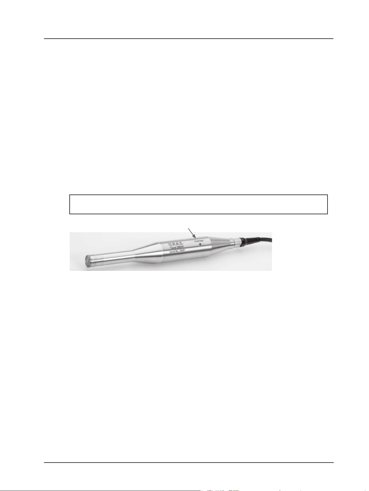
Fig. 1.1 shows a ½″ Low-noise Level Microphone System Type 40HH which comprises:
• ½″ Microphone Type 40AH.
• ½″ Preamplier Type 26HH with two built-in compensation lters and an overload-warning
LED.
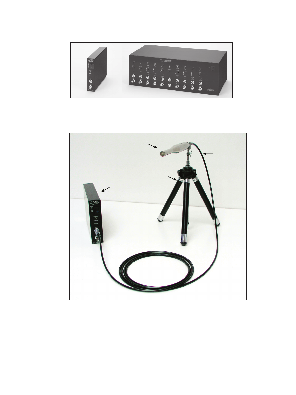
To complete the system, a special single or 10-channel power module is required and is avail-
able from G.R.A.S., i.e.
• Type 12HF for single-channel measurements, see Fig. 1.2 (left)
or
• Type 12HM for multi-channel (1 to 10) measurements, see Fig. 1.2 (right).
The chosen power module provides all necessary voltages for powering the preamplier(s) as
well as polarizing the microphone(s).
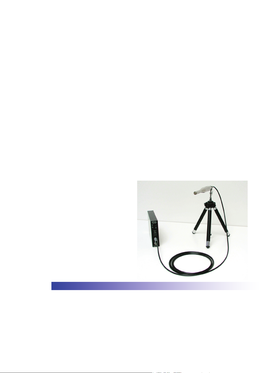
Fig. 1.3 shows a Single-channel Low-noise Measuring system (as described in this document)
and consists of:
• ½″ Low-noise Level Microphone System Type 40HH.
• Power Module Type 12HF.
Note: the power module must be ordered separately, and the tripod and tripod adapter are
optional extras.
Single-channel Low-noise Measuring System consisting of: Type 40HH and Type 12HF - Page 4
Overload-warning LED indicates when the measured
sound pressure level overloads the system’s electronics
Fig. 1.1 ½″ Low-noise Measurement Microphone System Type 40HH
1.1 Microphone Type 40AH
The Type 40AH is a special high-sensitive ½″ microphone. It is externally polarized with a specially reduced inherent noise oor in order to achieve a high dynamic range and wide frequency
range.
1.2 Preamplier Type 26HH
The body of the Preamplier has an overload-warning LED, (Fig. 1.1), which is repeated on the
front panel of the chosen power module (see Fig. 2.1).
The signal of the microphone is amplied by 20 dB in the Preamplier Type 26HH.
The two compensation lters give the system two parallel outputs which correspond to:
a) linear pressure-frequency response
b) linear free-eld frequency response at an angle of 0 ° incidence.
The choice of which frequency response to use is made via a two-position switch marked
Pressure / Free Field on the front panel of the chosen power module (see Fig. 2.1).
Fig. 1.4 shows the responses of the two compensation lters as well as the free-eld response
for 0 ° incidence. Note: free-eld corrections are added to the lowest curve.
Fig. 1.5 shows what these free-eld corrections are for various angles of incidence.
Fig. 1.6 shows, for a complete low-noise measuring system, a typical noise oor in ⅓-octave
bands for both the linear and A-weighted cases.
G.R.A.S. SOUND & VIBRATION
Page 5
Single-channel Low-noise Measuring System consisting of: Type 40HH and Type 12HF - Page 5
Fig. 1.2 Power modules available from G.R.A.S. for Type 40HH,
Left: Single-channel Power Module Type 12HF
Right: 10-Channel Module Type 12HM
½″ Low-noise Level Microphone
System Type 40HH
Tripod
Adapter
RA0093
Tripod
AL0006
Single or 10-channel power module
(here single channel Power Module
Type 12HF)
Fig. 1.3 A Single-channel Low-noise Measuring System as described in this document;
shown here with Tripod and Tripod Adapter (both available from G.R.A.S.)
G.R.A.S. SOUND & VIBRATION
Page 6

Single-channel Low-noise Measuring System consisting of: Type 40HH and Type 12HF - Page 6
Fig. 1.4 Typical frequency response curves of Type 40HH
14
12
0 º
10
8
90 º
6
4
120 º
2
0
Decibels re. level at 250 Hz
- 2
- 4
150 º
180 º
- 6
- 8
120 º
Fig. 1.5 Free-eld corrections for various angles of incidence on the ½″ Microphone Type 40AH
0 º
30 º
60 º
90 º
Random incidence
100 kHz10 kHz1 kHz100 Hz
G.R.A.S. SOUND & VIBRATION
Page 7

Single-channel Low-noise Measuring System consisting of: Type 40HH and Type 12HF - Page 7
Fig. 1.6 Typical noise oor of Type 40HH for system and microphone. Shown in ⅓-octave bands for both the linear
and A-weighted cases
G.R.A.S. SOUND & VIBRATION
Page 8

Single-channel Low-noise Measuring System consisting of: Type 40HH and Type 12HF - Page 8
2 Power Module Type 12HF
Since the microphone signal is amplied in the Preamplier Type 26HH by 20 dB, the nominal
system sensitivity at the output of the Power Module corresponds to 0.8 V/Pa. In other words
when the measured output voltage from the Power Supply is 0.8 V RMS, the microphone is
being subjected to 94 dB re. 20 μPa.
The actual sensitivity is quoted on the individual calibration chart supplied with each Type 40HH.
Important!
The Single-channel Power Module Type 12HF (available from G.R.A.S.) is a dedicated module.
Under no circumstances should any other Power Module (apart from the multi-channel Power
Module Type 12HM - also available from G.R.A.S.) be used with the ½″ Low-noise Level Micro-
phone System Type 40HH.
2.1 Front Panel
The front panel has the following features (see Fig. 2.1):
• Power switch with two LEDs: green “OK”, red “Batt. Low”.
If the power supply is correct, the green LED lights up. If the red LED lights up, either the
batteries are low and should be changed (see section 2.3) or the external DC supply voltage
is too low.
• Two-position switch for selecting frequency response, Pressure microphone operation or
Free Field microphone operation:
Pressure - to select the output of the compensating lter which gives the system a linear
pressure-frequency response.
Free Field - to select the output of the compensating lter which gives the system a linear
free-eld frequency response at 0 ° incidence.
• Overload-warning LED synchronised with the one on the Preamplier Type 26HH
(see Fig. 1.2).
Switch for
selecting either
pressure micro-
phone opera-
tion or free-eld
microphone
operation
Input 7-pin
LEMO socket
Output BNC
socket
Fig. 2.1 Front panel of the Power Module Type 12HF
G.R.A.S. SOUND & VIBRATION
Power switch
Green LED
power OK
Red LED Batt.
Low
Overload LED indicates
when the measured
sound pressure level
overloads the system’s
electronics
Page 9

Fig. 2.2 7-pin LEMO EGA 307 1B input socket
(external view)
• 7-pin LEMO EGA 307 1B input socket for the microphone and Preamplier signal. Wiring
diagram shown in Fig. 2.2.
• BNC output socket for the selected (Pressure / Free Field) output signal.
2.2 Rear Panel
The rear panel has the following features (see Fig. 2.3)
• Twist/release holder for 315 mA fast-blow fuse.
• Input socket for an external voltage supply of 6 V - 20 V DC; centre pin +terminal. Use the
Mains/line Adapter AB0010 supplied with the Type 12HF.
• Locking screw
Unscrew to remove base plate and gain access to the battery pack (see section 2.3).
Single-channel Low-noise Measuring System consisting of: Type 40HH and Type 12HF - Page 9
Fuse
315 mA
fast blow
Fig. 2.3 Rear panel of the Power Module Type 12HF
G.R.A.S. SOUND & VIBRATION
Input for external
Power Supply
6 V - 20 VDC
Locking screw for
base plate
Page 10

2.3 Battery Pack
To gain access to the battery pack, unscrew the locking screw on the rear panel (Fig. 2.3) and
slide the base plate off towards the rear. Pull out the battery pack See Fig. 2.4.
The battery pack consist of a battery holder and 4 x LR14 (C) standard alkaline cells. When
replacing the batteries, replace all of them making sure that the polarity is as indicated on the
battery holder.
Single-channel Low-noise Measuring System consisting of: Type 40HH and Type 12HF - Page 10
Fig. 2.4 Showing the battery pack of the Power Module Type 12HF
G.R.A.S. SOUND & VIBRATION
Page 11

Single-channel Low-noise Measuring System consisting of: Type 40HH and Type 12HF - Page 11
3 Calibration
3.1 Based on System Sensitivity
Since the microphone signal is amplied by 20 dB in the Preamplier Type 26HH, the nominal
system sensitivity at the output of the Power Module corresponds to 0.8 V/Pa. In other words
when the measured output voltage from the Power Module is 0.8 V RMS, the microphone is
being subjected to 94 dB re. 20 μPa.
The actual system sensitivity is quoted on the individual calibration chart supplied with each
Low-noise Microphone System Type 40HH.
Based on this information, proceed as follows:
1.. Connect the Type 40HH via its LEMO plug to the LEMO input socket of the Type 12HF.
2. Connect via a suitable cable the BNC output of the Type 12HF to the analyser to be used
and switch both Power Module and analyser on.
3. Adjust the analyser to indicate 94 dB re. 20 μPa for an RMS input of S volts; where S is the
system sensitivity of the Type 40HH as quoted on the calibration chart.
3.2 Level Calibration using a Pistonphone
A Pistonphone Type 42AA tted with a Coupler RA0090 (both available from G.R.A.S.) can be
used to produce 94 dB re. 20 μPa on the microphone of the Type 40HH.
Note: a Pistonphone tted with a normal ½″ coupler cannot be used because this will overload
the system with a level of 114 dB re. 20 μPa.
Proceed as follows:
1 Connect the Type 40HH via its LEMO plug to the LEMO input socket of the Type 12HF.
2. Connect via a suitable cable the BNC output of the Type 12HF to the analyser to be used
and switch both Power Module and analyser on.
3. Unscrew and remove the normal coupler of the Pistonphone.
4. Screw the Coupler RA0090 to the Pistonphone, see Fig. 3.1.
5. Push t the ½″ adapter RA0181 shown Fig. 3.1 to the entrance of the coupler RA0090.
6. Mount the microphone of the Type 40HH in the Coupler as shown in Fig. 3.2 and switch the
Pistonphone on.
Fig. 3.1 Pistonphone without its normal coupler and ready to accept the Coupler
RA0090
G.R.A.S. SOUND & VIBRATION
Adapter for ½″ microphone
RA0181
Page 12

Single-channel Low-noise Measuring System consisting of: Type 40HH and Type 12HF - Page 12
Fig. 3.2 Pistonphone tted with Coupler RA0090 and the
microphone inserted into the Coupler
7. Adjust the analyser to indicate 94 dB* re. 20 μPa.
3.3 Frequency Response Calibration
The frequency response of the microphone has been factory-calibrated in a free eld (anechoic
chamber) by comparison with a reference microphone.
Due to the high sensitivity of the microphone and undamped microphone resonance, the microphone response around the resonance frequency may be inuenced by the loading of the
microphone diaphragm from the electrosatic actuator.
* Plus any corrections for barometric pressure. See pistonphone manual.
G.R.A.S. SOUND & VIBRATION
Page 13

Single-channel Low-noise Measuring System consisting of: Type 40HH and Type 12HF - Page 13
4 Measurements
1. Assemble the system as shown in Fig. 1.3.
2. Connect the output from the Power Module to an analyser.
3. Switch both Power Module and analyser on.
4. Calibrate the set up via one of the methods described in section 3.1.
5. Select which microphone operation to use via the switch on the front panel of the
Type 12HF marked Pressure / Free Field.
At this point you can make your measurements but keep an eye on the overload warning LEDs
to avoid overloading the system and invalidating the measurements.
G.R.A.S. SOUND & VIBRATION
Page 14

Single-channel Low-noise Measuring System consisting of: Type 40HH and Type 12HF - Page 14
5 Specications
5.1 ½″ Low-noise Microphone System Type 40HH
Low-noise Microphone System Type 40HH comprising:
½″ Microphone: Type 40AH
Preamplier: Type 26HH (with 3 m cable and LEMO FGA.1B.307 plug)
Frequency response:
12.5 Hz - 10 kHz ±1.0 dB10 Hz - 16 kHz: ±2.0 dB
6 Hz - 20 kHz: +2.0 dB, –3.0 dB
Nominal sensitivity:
System: 800 m V/Pa ±2 dB
Microphone polarization voltage:
200 V
Dynamic range:
Upper limit: 113 dB re. 20 µPa
Lower limit: 6.5 dBA re. 20 µPa (inherent noise)
Microphone capacitance:
20 pF
5.2 Single-channel Power module Type 12HF (separate order)
Input channel:
7-pin LEMO EGA 1B connector
Outputs channel:
BNC socket
Output impedance:
30 Ω
Polarization voltage:
200 V
Power supply:
Internal: 6 V from 4 x LR14 (C) standard alkaline cells
External: 6 V - 20 V DC via included Mains Adapter AB0010
Dimensions:
Height: 132.6 mm (5¼ in)
Width: 34.6 mm (1.3 in)
Depth: 196.0 mm (7.7 in)
Weight:
620 g (1.3 lbs)Weight:
620 g (1.3 lbs)
G.R.A.S. SOUND & VIBRATION
Page 15

Single-channel Low-noise Measuring System consisting of: Type 40HH and Type 12HF - Page 15
5 What to Order
Type 40HH includes:
Batteries: 4 x LR14 (C) standard alkaline cells
Mains/line Adapter: AB0010
Optional Accessories
Power module (1 ch.): Type 12HF
Power module (10 ch.): Type 12HM
Windscreens (set of 5): AM0069
Pistonphone: Type 42AA
Pistonphone Coupler: RA0090 (for 94 dB re. 20 µPa)
Tripod: AL0006
Tripod Adapter: RA0093
3 m Ext. cable: AA0046
10 m Ext. cable: AA0047
30 m Ext. cable: AA0048
G.R.A.S. SOUND & VIBRATION
Manufactured to conform with:
CE marking directive:
93/68/EEC
WEEE directive:
2002/96/EC
RoHS directive:
2002/95/EC
 Loading...