

www.gras.dk
LI0083 – Revision 22 June 2017
Instruction Manual
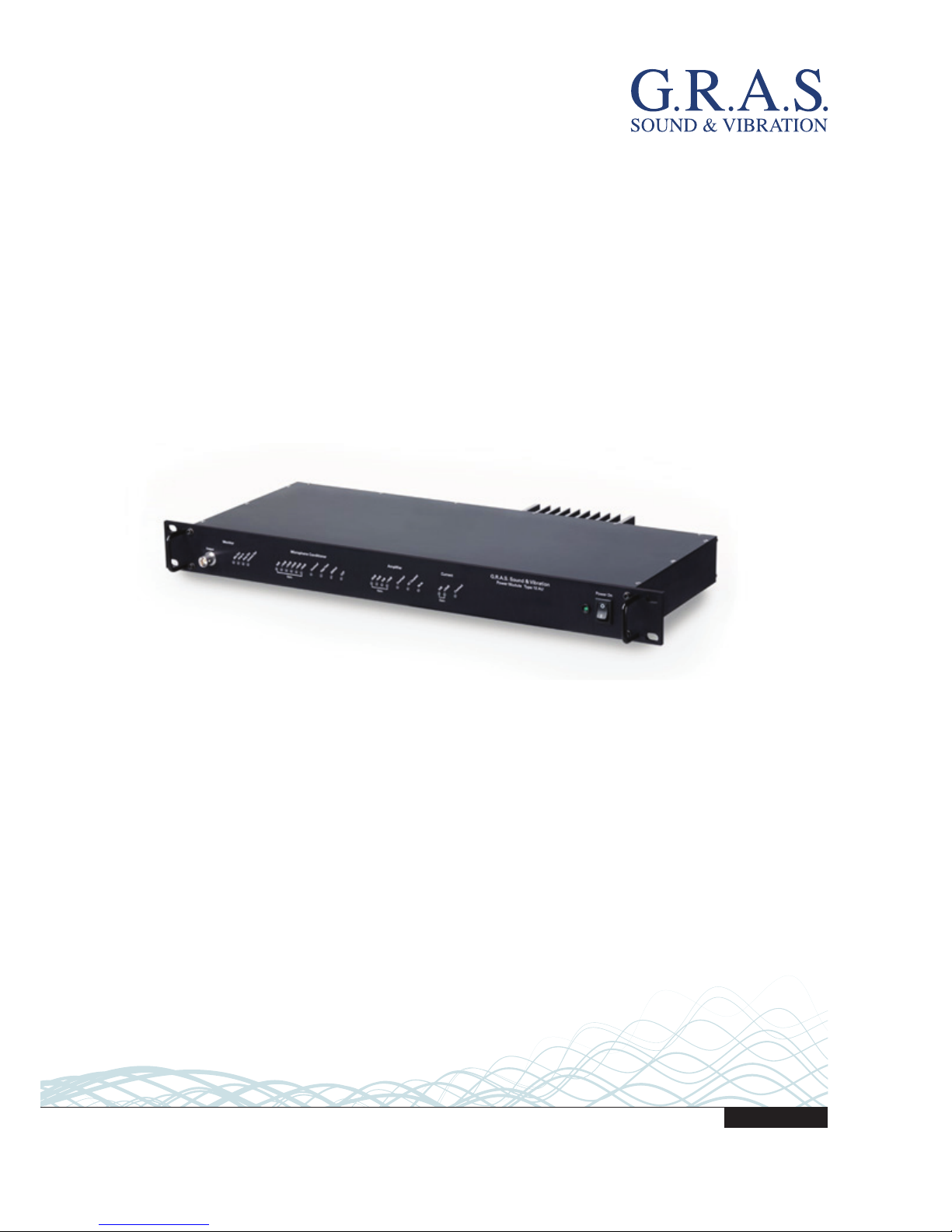
12AU 1-Channel Power Module
with Signal Conditioning and Power Amplifier
2
LI0083 – Revision 22 June 2017
Revision History
Any feedback or questions about this document are welcome at gras@gras.dk.
Revision Date Description
1 7 November 2012 Tentative version
2 14 December 2012 First publication
3 18 December 2012 Minor corrections to General Description
4 29 November 2016 Correction to page 10, amplifier input impedance
5 22 June 2017 Specs. for power amplifier output voltage swing changed
to ±13.5 V
Copyright Notice
© 2012-17 G.R.A.S. Sound & Vibration A/S
http://www.gras.dk
Any technical documentation that is made available by G.R.A.S. is the copyrighted work of
G.R.A.S. and is owned by G.R.A.S.
The content in this document is subject to change without notice. G.R.A.S. Sound & Vibration A/S
is not liable or responsible for any errors or inaccuracies that may appear in this document.
Trademarks
Product names mentioned in this document may be trademarks or registered trademarks of their
respective companies and are hereby acknowledged.

3
LI0083 – Revision 22 June 2017
Contents
General Description ....................................................................... 4
Features ................................................................................................... 4
Microphone Conditioner .............................................................................. 5
Speaker Amplifier ...................................................................................... 6
Monitor Section ......................................................................................... 6
Power Supply ............................................................................................ 6
Physical Interface .......................................................................... 7
Front Panel ............................................................................................... 7
Rear Panel .............................................................................................. 10
The 12AU Behavior and Protocol Specification .................................. 11
Interface and Protocol Specification ............................................................ 11
List of Commands and Responses ............................................................. 12
Installing the USB-driver and Control Software ................................. 18
Installing the USB Driver ........................................................................... 18
Installing the Control Software ................................................................... 19
Preparing the 12AU for Measurements ............................................ 21
Cables and Connections ............................................................................ 21
Multi-channel Measurements .................................................................... 22
Operating the 12AU via its PC Application ....................................... 23
Using the Graphical User Interface ............................................................. 23
The Setup Menu ...................................................................................... 24
The Tools Menu ....................................................................................... 24
The Help Menu ........................................................................................ 28
Operating the 12AU Using Commands ....................................................... 28
Dealing with Overload in a Production Setup..................................... 29
Overload Caused by Handling .................................................................... 29
Minimizing Overload ................................................................................ 29
Appendix ................................................................................... 30
Updating the USB driver ........................................................................... 30
Technical Specifications ................................................................ 33
Warranty and Service ................................................................... 34
Warranty ................................................................................................. 34
Service and Repairs .................................................................................. 34

4
LI0083 – Revision 22 June 2017
General Description
The G.R.A.S. 12AU Power Module is a supply and conditioning amplifier for simultaneously
powering a preamplifier for a condenser microphone and an amplifier for a loudspeaker or any
other sound source using a loudspeaker/earphone/coupler. By design, it avoids system-generated
noise, e.g. from ground loops. In a measurement set-up, the 12AU controls both the paths of the
signal sent out to the loudspeaker and the resulting acoustic signal picked up by the microphone.
In both cases, its set-up for handling these signals independently comes under external control.
The 12AU is remote controlled entirely via its USB interface, and, for this purpose, is delivered with
a control program for Microsoft Windows
®
. Settings on the 12AU can be controlled by the control
software’s graphical user interface and easily confirmed by the LEDs on the front panel. See “Using
the Graphical User Interface” on page 23 for instructions. It is also possible to operate the 12AU
typing commands in its View Log window, see “Operating the 12AU Using Commands” on page
28.
It is optimized for computerized production line testing. Up to six 12AUs can be connected to and
operated from the same PC.
Features
• Single channel conditioning amplifier for microphone preamplifier and speaker amplifier with
measurement of current output
• Controls the paths of the outgoing and received signals at the same time
• Very low inherent noise
• The speaker input and the analogue outputs are floating with respect to common ground to
avoid system-generated noise
• Measurement of loudspeaker impedance without disturbing the speaker
• Fulfils EMC requirements according to EU regulations
• Full remote control via USB interface
• LEMO input with 200 V polarization voltage for externally polarized microphone
• CCP input for prepolarized microphone
• Gain settings for noise and overload control:
– Microphone conditioner: 0 to 50 dB in 10 dB steps
– Speaker amplifier: –20 dB to +10 dB in 10 dB steps
– Current output: 0 dB and +20 dB
• Filters:
– Microphone amplifier: 1 Hz or 20 Hz
– Speaker amplifier: DC or AC coupling (10 Hz)
• Comprehensive status and overload indication
• Rack mountable in 19” rack.

5
LI0083 – Revision 22 June 2017
Microphone Conditioner
Input and output
The 12AU has two microphone inputs, a LEMO input for externally polarized microphones and a
CCP input for prepolarized microphones.
The LEMO input has a 7-pin LEMO 1B socket for a microphone preamplifier such as the
G.R.A.S. Preamplifiers 26AM, 26AC, and 26AK. Fig. 1 shows the wiring diagram of this input
socket which is also compatible with a range of microphone preamplifiers from other suppliers
such as Norsonic, L&D and Brüel & Kjær. The input impedance is 100
kΩ.
Fig. 1. 7-pin LEMO female socket 1B (external view).
The CCP input has a standard BNC socket.
The Microphone Output is a standard BNC socket for direct use with analyzers, voltmeters, oscilloscopes etc. The output is floating (2 kΩ//100 nF to common ground). The output impedance is
100 Ω.
Input for Externally Polarized Microphone or Pre-polarized Microphone (CCP)
The 12AU has a 7 pin LEMO socket for a microphone with a LEMO type preamplifier and a BNC
socket for a CCP microphone set.
The polarization voltage can be set to 200 V or 0 V, a green LED on the front indicates the
currently selected polarization voltage.
The preamplifier voltage supply is ±15 V DC. The CCP supply is 4 mA.
Bandwidth, Filters and Noise
The bandwidth of the Microphone Conditioner is from 1 Hz to 100 kHz (–3 dB). A 20 Hz
(Butterworth 3. order) high-pass filter can be selected remotely. A front-panel LED lights up when
the filter is switched on.
The noise floor relative to input, with the input shorted, is (≥20 dB gain) <1.5 μVrms
(20 Hz - 20 kHz). With the input loaded with a 20 pF dummy microphone, the noise is less than
5 μVrms (20 Hz – 20 kHz).

6
LI0083 – Revision 22 June 2017
Gain
The gain can be set to one of the following: 0 dB, +10 dB, +20 dB, +30 dB, +40 dB or +50 dB
(± 0.2 dB). One of a series of front-panel LEDs lights up to indicate the current gain setting.
Overload Detection
If either of the conditioning amplifier stages goes into overload, this is indicated by a red LED.
Gain and filter settings can be optimized to improve headroom/reduce overloads.
Speaker Amplifier
The speaker amplifier has a bandwidth (-3 dB) from DC to 80 kHz (DC coupled) and from
10 Hz – 80 kHz (AC coupled). AC or DC coupling is set remotely.
Phase shift (input to output) is ≤
±1° (DC to 20 kHz). The maximum output voltage is ±13.5 V,
the maximum output current
±1.4 A. The current output (voltage/current ratio) can be set to
1 V/1 A or 10 V/1 A (remote controlled).
Input and output
The input connector is a standard BNC socket, floating with 10 kΩ//100 nF to common ground.
The input impedance is 10 kΩ.
The speaker amplifier has two outputs, a voltage output and a current output. The voltage output
connector is a 2 pin LEMO (pin 1 is output, pin 2 is return). The current output connector (remote
controlled) is a BNC socket, floating with 2 kΩ//100 nF to common ground.
Gain
The gain can be set in steps of 10 dB (±0.2 dB), from –20 dB to +10dB. One of a series of front
panel LEDs lights up to indicate the current gain setting.
Overload
Voltage and current overload detection are indicated by separate LEDs on the front panel (remote
controlled reading and reset).
Monitor Section
The signals that are fed to and taken out of the 12AU can be monitored via the monitor BNC
output socket. Front panel LEDS indicate the actual selection: Mic Out, Amp In., Amp Out,
Current Out.
Power Supply
The 12AU can be powered from a mains/line supply of either 115 V AC or 230 V AC ,
selected with a switch on the rear panel.
7
LI0083 – Revision 22 June 2017
Physical Interface
Front Panel
The 12 AU is designed for mounting in a 19” rack.
Mic Out
Amp In
Amp Out
Cu
r
rent Out
+20dB
+30dB
+40dB
+50dB
Monitor
Microphone Conditioner
Overload
High
P
ass
200Volt
CCP
-20dB
-
10dB
0dB
+10dB
Overload
AC Coupled
Mute
Amplier
Overload
0dB
+20dB
Current
G.R.A.S. Sound &Vibration
Power Module Type 12AU
Gain
Gain
Gain
Output
0dB
+10dB
Power On
I
O
Fig. 2. Green LEDs show the operational status and red LEDs warn about overload.
When the 12AU is switched on, the default settings will be applied. All LEDs are lit for a few
seconds to show that the 12AU is working properly. After approximately 10 seconds, it switches
to operational mode.
Selections are made via the USB connection on the rear panel using the accompanying control
software.
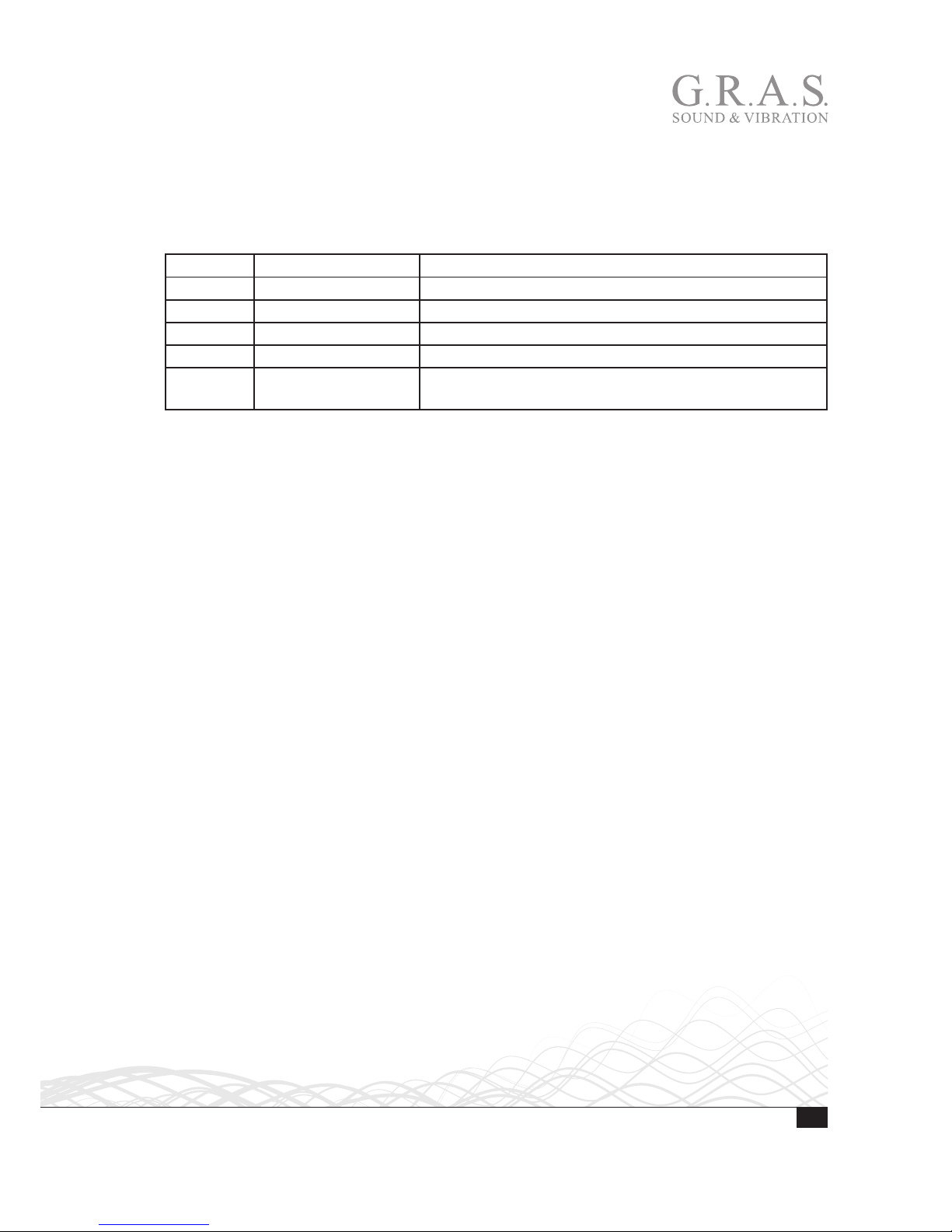
The Monitor Section
The Monitor function of the 12AU makes it possible to monitor the input and output signals via
separate sockets, one on the front and another on the back.
Mic Out
Amp In
Amp Out
Cu
rrent Out
+20dB
+30dB
+40dB
+50dB
Monitor
Microphone Conditioner
Overload
High
P
ass
200
V
olt
CCP
-20dB
-10dB
Gain
Gain
Output
0dB
+10dB
Current Out LED. Lit when the
amplifier current output is selected.
Amp Out LED. Lit when the
amplifier output signal is selected.
Amp In LED. Lit when the amplifier
intput signal is selected.
Mic Out LED. Lit when the microphone output signal is selected.
Output. BNC socket for monitoring the output signal.
8
LI0083 – Revision 22 June 2017
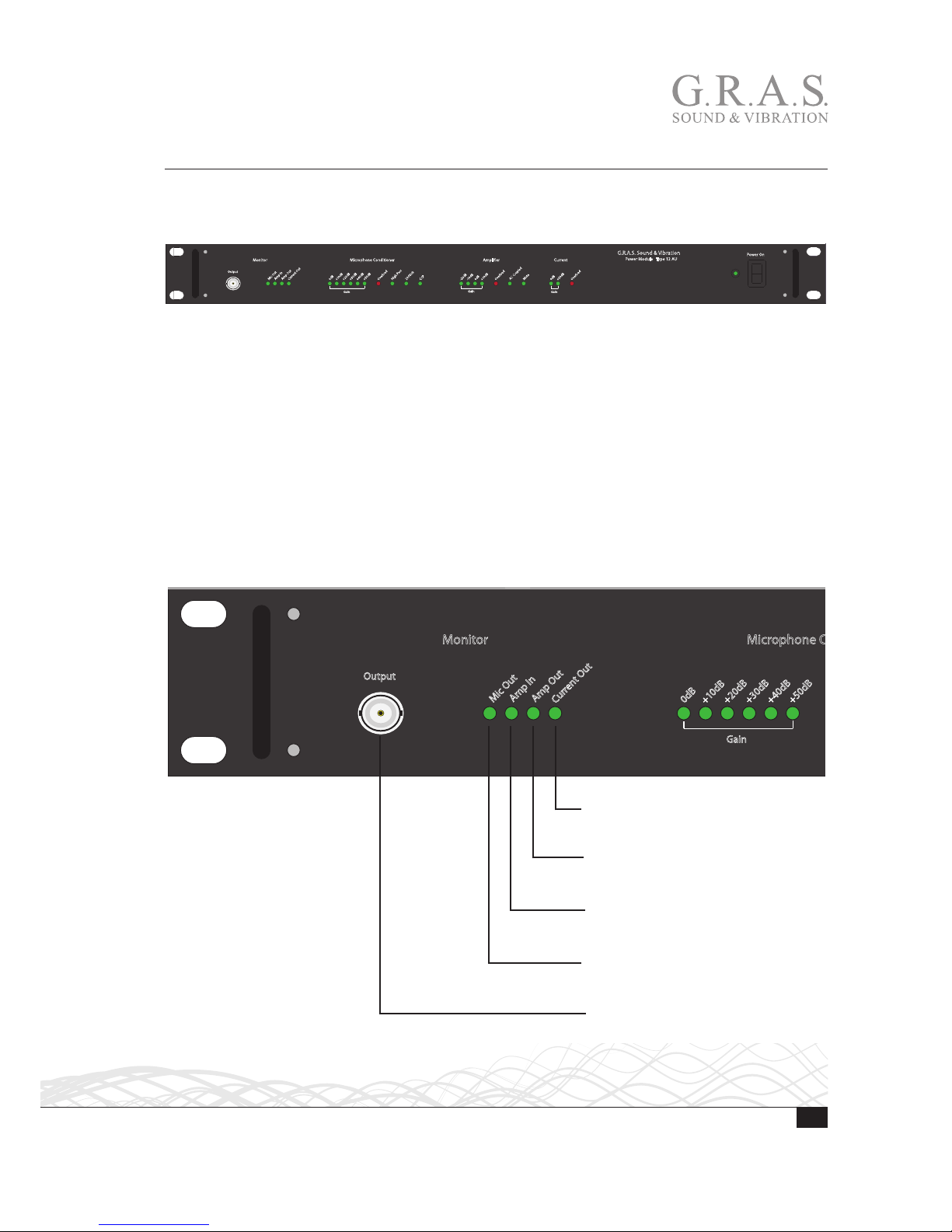
Microphone Conditioner Section
These LEDs indicate the current preamplifier-input status which is controlled via the USB interface connection on the rear panel.
+20dB
+30dB
+40dB
+50dB
Microphone Conditioner
Overload
High
P
ass
2
0
0Volt
CCP
-20dB
-1
0dB
0dB
+
1
0dB
Overload
A
C Coupled
Mute
Amplier
Overload
0dB
+20dB
Current
Gain
Gain
Gain
0dB
+1
0dB
Gain LEDs. Indicates current gain setting.
Gain settings are from 0 dB to + 50 dB in
10 dB steps.
Input Overload LED. Lit when
microphone signal overloads the 12AU.
Overloads can be latched and read via
the USB interface, in which case they are
cleared when read. Alternatively, overload
messages can be signalled to remote control, displayed briefly and cleared automatically.
High Pass (20 Hz) LED. Lit when high-pass
filter is active. Otherwise, full-bandwidth
conditions apply, i.e. 1 Hz to 100 kHz
(– 3 dB). When fast settling is enabled, the
High Pass LED will flash during settling.
200 V LED Lit when then 200 V Polarization is enabled.
CCP LED. Lit when the CCP input is enabled.
9
LI0083 – Revision 22 June 2017
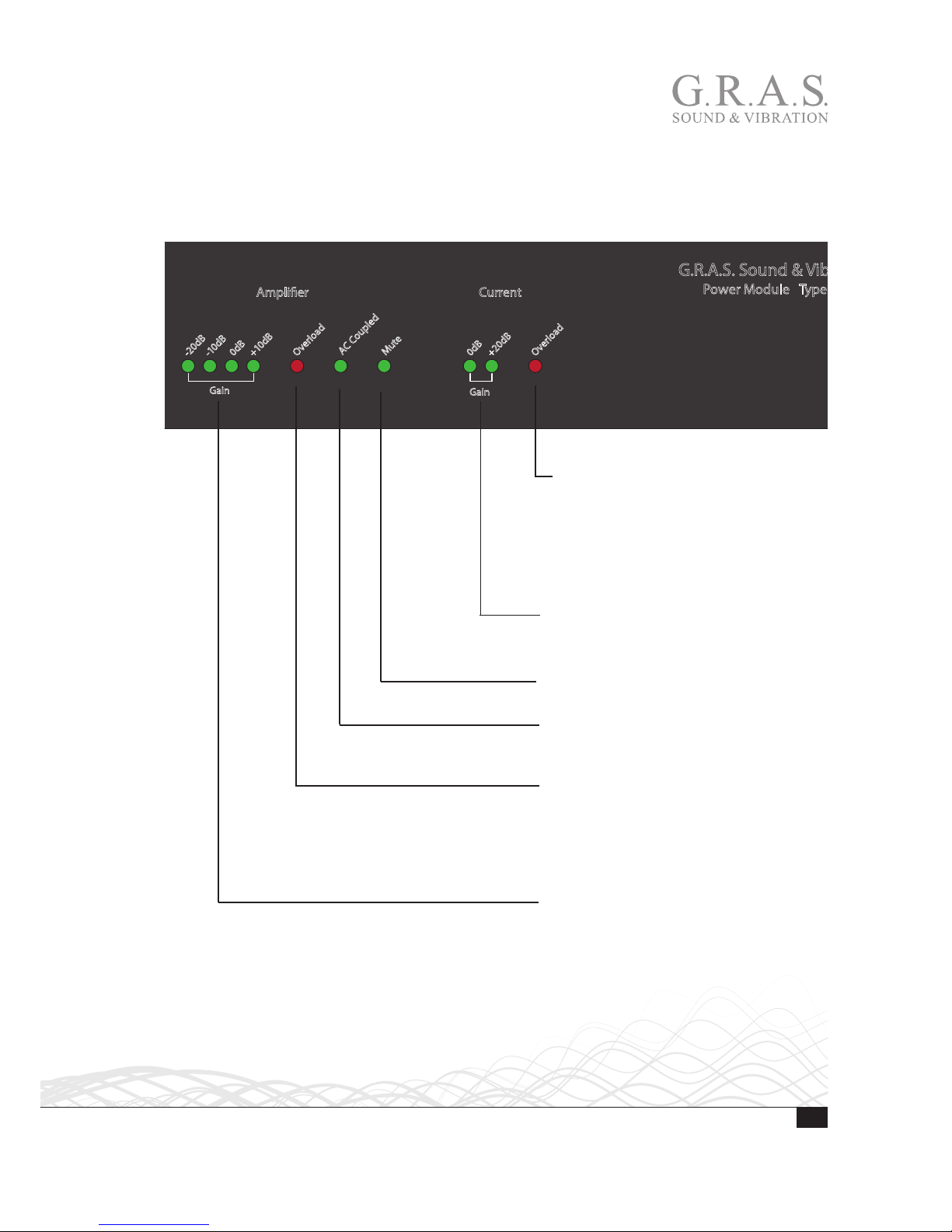
Amplifier Section
These LEDs indicate the status of the amplifier which is controlled via the USB interface connection on the rear panel. The amplifier can be set to voltage or current amplification, with separate
gain and overload settings for each mode.
-20dB
-1
0dB
0dB
+10dB
Overload
A
C Coupled
Mute
Amplier
Overload
0dB
+20dB
Current
G.R.A.S. Sound & V
ibration
Power Module T
ype 12 AU
Gain
Gain
Power On
I
O
Gain LEDs. Indicates the actual gain setting. Gain settings are from –20 dB to +
10 dB in 10 dB steps.
AC-Coupled Lit when output is
AC-coupled. When not lit the output is
DC-coupled.
Current Gain LED. The LED indicates the
actual current gain setting, 0 dB or +20 dB.
Current overload LED. Lit when current
output goes into overload. Overloads can
be latched and read via the USB interface, in which case they are cleared when
read. Alternatively, overload messages can
be signalled to remote control, displayed
briefly and cleared automatically.
Overload LED. Overloads can be latched
and read via the USB interface, in which
case they are cleared when read. Alternatively, overload messages can be signalled
to remote control, displayed briefly and
cleared automatically.
Mute LED. Lit when output is muted.
10
LI0083 – Revision 22 June 2017
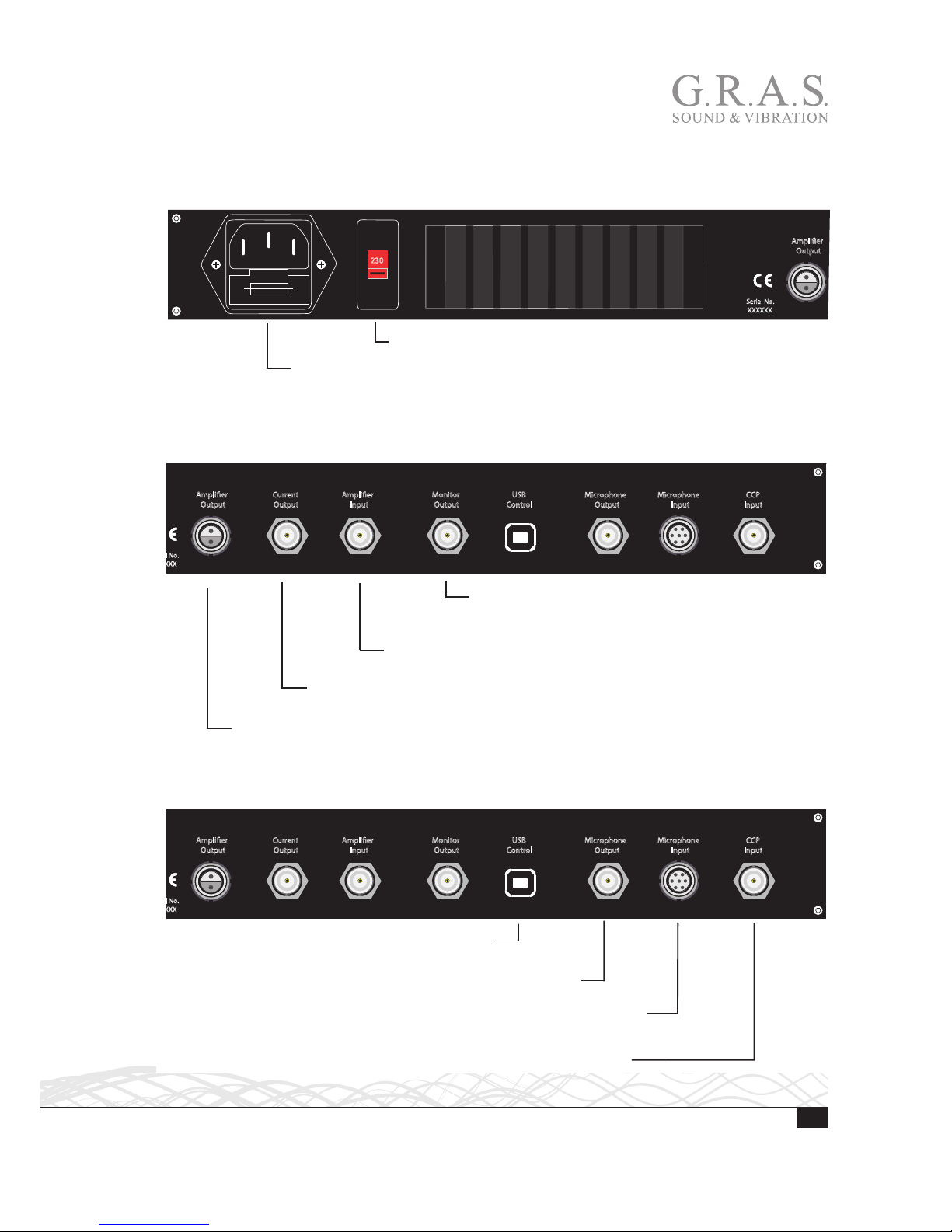
Rear Panel
Mains Input and Voltage Setting
Amplier
Output
Current
Output
Amplier
Input
Monitor
Output
USB
Control
Serial No.
XXXXXX
230
Voltage Setting Switch for either 115 VAC or 230 VAC.
Mains Input and Fuse Holder. Input socket for either 115 VAC or 230 VAC
mains supply. Fuse holder for 1 A slow fuse.
Monitor and Amplifier Sockets
Amplier
Output
Current
Output
Amplier
Input
Monitor
Output
USB
Control
Microphone
Output
Microphone
Input
CCP
Input
Monitor Output. BNC output socket for monitoring the
currently selected signal. Output impedance is 100 Ω.
Also repeated on the front panel.
Amplifier Input. BNC input socket for signal to the speaker amplifier,
for example from a signal generator. Input impedance is 10
kΩ.
Current Output. BNC output socket for a voltage signal proportional to the current
through the output circuit of the speaker amplifier.
Amplifier Output. 2-pin LEMO connector for a loudspeaker with an impedance of 2 Ω or more.
USB and Microphone Sockets
Amplier
Output
Current
Output
Amplier
Input
Monitor
Output
USB
Control
Microphone
Output
Microphone
Input
CCP
Input
USB Control. USB socket for connection to a USB
computer port.
Microphone Output. BNC output socket for the microphone signal.
Microphone Input. 7-pin LEMO input connector for microphone preamplifier.
The wiring diagram is shown in Fig. 1.
CCP Input. BNC Input connector for Constant Current Powered transducers.

11
LI0083 – Revision 22 June 2017
The 12AU Behavior and Protocol Specification
Interface and Protocol Specification
Compatibility
The 12AU protocol specification complies with the 12AP specification version 1.2, where applicable. (The Floating command is omitted).
USB Interface
There is no flow control/handshaking; therefore commands must be sent one by one, waiting for
the response.
The input buffer is 64 bytes, in case of overflow a response: “Buffer overflow” will be submitted.
This will not happen under normal conditions.
12AU Startup Sequence
After power on or restart, the 12AU immediately initializes the settings of 12AU to current
default settings and turns on all LEDs.
If connected to PC, the OVL leds will be turned off when then USB connection is established,
typically after 4 seconds from power on.
Appoximate after 8 seconds the IRQ and overload system is enabled, the LED will reflect the
setting and a Reset<crlf> is submitted.
Behavior
A watchdog is enabled. It will restart 12AU if the processor stops working – this will send the
string Reset<crlf> to the host. In this case the host knows that the fault has occurred and will
be able to reinitialise 12AU.
Commands
Note: <LF> in input will be ignored, and commands are in uppercase.

12
LI0083 – Revision 22 June 2017
List of Commands and Responses
Microphone Conditioner
CCP
CCP Y<cr> CCP input enabled.
CCP N<cr> CCP input disabled.
Gain
G0<cr> set the conditioning amplifier gain to 0 dB.
G10<cr> set the conditioning amplifier gain to 10 dB.
G20<cr> set the conditioning amplifier gain to 20 dB.
G30<cr> set the conditioning amplifier gain to 30 dB.
G40<cr> set the conditioning amplifier gain to 40 dB.
G50<cr> set the conditioning amplifier gain to 50 dB.
Polarization Voltage
P200<cr> set polarization voltage to 200 V.
P0<cr> set polarization voltage to 0 V.
High Pass Filtering
HP1<cr> set the conditioning amplifier high pass filter to 1 Hz.
HP20<cr> set the conditioning amplifier high pass filter to 20 Hz.
HP20L<cr> set the conditioning amplifier high pass filter to 20 Hz
with gain applied late in the chain.
Overload Handling
LATCH<cr> set the conditioning amplifier to latch overloads.
Overloads are latched, and cleared when read.
No overload messages will be sent.
OVLTM M<cr> set the conditioning amplifier hold time for overload to
minimum.
OVLTM #<cr> set the conditioning amplifier hold time for overload to
# sec. (1s. default).

13
LI0083 – Revision 22 June 2017
OVLLED Y<cr> set the conditioning amplifier to display overload.
(default).
OVLLED N<cr> set the conditioning amplifier to not display overload.
(not recommended).
Speaker Amplifier
SG-20<cr> set the speaker amplifier gain to –20 dB.
SG-10<cr> set the speaker amplifier gain to –10 dB.
SG0<cr> set the speaker amplifier gain to 0 dB.
SG10<cr> set the speaker amplifier gain to 10 dB.
SMUTE Y<cr> mute speaker amplifier.
SMUTE N<cr> enables speaker amplifier.
SHP0<cr> DC couples speaker amplifier.
SHP10<cr> AC couples speaker amplifier HP 10 Hz.
Overload Latching
SLATCH<cr> set the speaker amplifier to latch overloads
overload’s are latched, and cleared when read.
No overload messages will be sent.
Gain
CG0<cr> set the speaker amplifier gain to 0 dB.
CG20<cr> set the speaker amplifier gain to 20 dB.
Current Overload Latching
CLATCH<cr> set the speaker amplifier to latch current overloads.
Overload’s are latched, and cleared when read. No
overload messages will be sent.
Fast Settling
FastSettling #<cr> Set the period of fast settling to [#] sec. Enabling
fast settling after change of setup in # sec. (Inserts
HP50Hz for [#] sec.)
FastSettle<cr> Enables fast settling in the predefined period, the period
is defined with the command FastSettling #

14
LI0083 – Revision 22 June 2017
Monitoring
Monitor Conditioning<cr> sets monitor to Conditioning Amplifier Output.
Monitor Speaker in<cr> sets monitor to Speaker Amplifier Input.
Monitor Speaker out <cr> sets monitor to Speaker Amplifier Output.
Monitor Current<cr> sets monitor to Current Amplifier Output.
MLATCH<cr> set the Speaker Amplifier to latch current overloads.
Overload’s are latched, and cleared when read. No
overload messages will be sent.
The Monitor Conditioning amplifier does not sent overload messages.
Special Commands
MSG<cr> set the Conditioning amplifier to submit an overload
message when its overload status changes, returns
actual overload status: OVL_on <crlf> or OVL_
off<crlf>, overload is not latched.
OVL<cr> reads overload status, and returns OVL_on <crlf> or
OVL_off <crlf>. Latched overloads will be reset by
reading the status.
SMSG<cr> set the speaker amplifier to submit an overload
message when its voltages overload status changes,
returns actual overload status: SOVL_on <crlf> or
SOVL_off <crlf>, overload is not latched.
SOVL<cr> reads overload status, and returns SOVL_on <crlf>
or SOVL_off <crlf>. Latched overloads will be reset
by reading the status.
CMSG<cr> set the Speaker amplifier to submit an overload
message when its current overload status changes,
returns actual overload status: COVL_on <crlf> or
COVL_off <crlf>, overload is not latched.
COVL<cr> reads overload status, and returns COVL_on <crlf>
or COVL_off <crlf>. Latched overloads will be reset
by reading the status.
MMSG<cr> set the Monitor rear output to submit an overload
message when its overload status changes, returns
actual overload status: MOVL_on <crlf> or MOVL_
off <crlf>, overload is not latched.

15
LI0083 – Revision 22 June 2017
MOVL<cr> reads overload status, and returns MOVL_on <crlf>
or MOVL_off <crlf>. Latched overloads will be reset
by reading the status.
INFO<cr> is equivalent to sending the commands TYPE,
SERIAL and FIRMWARE.
TYPE<cr> returns: G.R.A.S. Type 12AU <crlf>.
SERIAL<cr> returns: Serial no.: xxxxx <crlf>.
FIRMWARE<cr> returns: Firmware ver. 1.1 <crlf>.
G<cr> returns: conditioning Gain: 50dB, 40dB, 30dB, 20dB,
10dB or 0dB.
SG<cr> returns: speaker Gain: -20dB, -10dB, 0dB or 10dB.
SMUTE<cr> returns: Speaker enabled or Speaker muted.
CG<cr> returns: current Gain: 0dB or 20dB.
HP<cr> returns: Conditioning lter: 0.7Hz, 20Hz or
20Hz late gain.
SHP<cr> returns: Speaker lter: 0Hz or 10Hz.
Monitor<cr> returns: selected monitor: Conditioning,
Speaker in, Speaker out or Current.
Name<cr> returns: User selected name of the unit.
Name “text” saves the text in 12AU as a user selected name of the
unit, the USB connection is disabled during this and
12AU restarts when ready.
Pol<cr> returns: Polarization voltage: 0V or 200V.
CCP<cr> returns: CCP status: enabled or disabled.
FastSettling<cr> returns: FastSetling time: #.# S.
OVLTM<cr> returns: Overload hold time: #.# S.
T<cr> returns: speaker amplifier temperature in deg C°.

16
LI0083 – Revision 22 June 2017
Special Responses
Reset<crlf> submitted when 12AU is powered on.
OVL_on<crlf> submitted when OVL is received or in message mode
when conditioning amplifier overload status changes. It
reflects the overload status.
OVL_off<crlf> see OVL_on<crlf>.
SOVL_on<crlf> submitted when SOVL is acquired or in message mode
when speaker voltages overload status changes. It
reflects the overload status.
SOVL_off<crlf> see SOVL_on<crlf>.
COVL_on<crlf> submitted when COVL is acquired or in message
mode when speaker amplifier current overload status
changes. It reflects the overload status.
COVL_off<crlf> see COVL_on<crlf>.
MOVL_on<crlf> submitted when MOVL is acquired or in message mode
when Monitor rear output overload status changes. It
reflects the overload status.
MOVL_off<crlf> see MOVL_on<crlf>.
Overload Response in Latch Mode
For each of the overload detectors, an internal overload status flag is reflecting the actual overload condition. The overload status flag will be set when an overload occurs.
In latch mode, the status flag and the LED will be set by an occurrence of overload. It can only be
reset after the overload condition has been removed and the overload status is read by sending
the OVL<cr> command (SOVL, COVL or MOVL respectively).
Note: The command: OVLLED N<cr> will disable the conditioning amplifier’s overload LED, the
behavior in all other ways is unchanged.
Note: the Monitor rear output has no overload LED indication, it can only be read via the USB
interface.

17
LI0083 – Revision 22 June 2017
Overload Response in Message Mode
When an overload detector is in message mode, the respective overload LED will follow the
overload status flag, unless it is disabled by the command: OVLLED N<cr>.
The Overload LED will light under overload condition; it will turn off approximately one second
after the condition has been removed. For the conditioning amplifier, the time can be shortened
by the command: OLVTM M<cr>.
When the overload state changes, the message sent will be:
OVL_on<crlf> or OVL_off<crlf> or
SOVL_on<crlf> or SOVL_off<crlf> or
COVL_on<crlf> or COVL_off<crlf> or
MOVL_on<crlf> or MOVL_off<crlf>.
If an overload occurs while a command is sent to the 12AU, the overload status will not be read
and no response sent back until the command has been processed.
Restart and Default
Restart<cr> Restarts 12AU.
Factory_default<cr> Loads factory default values,
Load_default<cr> Loads current default values
Save_default<cr> Saves current setup values as default, the USB connection
is disabled during this and 12AU restarts when ready.
Default Settings
The conditioning amplifier powers up in default mode, which can be user defined. The factory
defined default mode is:
• Conditioning amplifier gain 0 db
• Conditioning amplifier polarization 200 V
• Conditioning amplifier high pass filter 1Hz
• Displays overload
• Overload hold time 1 sec.
• Overload mode is Message mode
• Speaker amplifier gain –20 dB
• Speaker enabled.
• Speaker amplifier high pass filter 10 Hz
• Current output gain 0 dB
• CCP input disabled
• FastSettling disabled
• Monitor set for Conditioning amplifier

18
LI0083 – Revision 22 June 2017
Installing the USB-driver and Control Software
The 12AU is operated remotely via its USB interface. Before connecting the 12AU to your
computer, you need to install the USB driver and the control software for the 12AU.
Important: Do not connect the 12AU to the PC before installing the device driver.
If you already have done so, you need to update the driver from the Device Manager with the one
found on the USB stick in the directory usb_driver! Refer to “Updating the USB driver” on page
30 for information on how to do this.
Installing the USB Driver
Prior to connecting the 12AU, you must install the dedicated USB device driver on the PC that
you will use to operate the 12AU.
Important. The installation requires that you are logged in as administrator on the PC.
1. Insert the 12AU USB stick delivered with the 12AU in your PC.
2. In Windows Pathfinder, open the 12AU Installation USB.
3. Open the usb_driver directory containing the USB driverinstaller.
4. Click on the USBDriverinstaller Icon.
5. Click on the Install Drivers button and wait for confirmation.
If you have already connected the 12AU, the installation will fail and you need to remove the
Windows USB driver manually by updating the USB driver using the Windows Device Manager.
For instructions on how to do this, see “Updating the USB driver” on page 30.

19
LI0083 – Revision 22 June 2017
Installing the Control Software
Introduction
The control software for the 12AU is installed from the installation USB. Windows XP, Windows
Vista, or Windows 7 is required.
Screen resolution must be set to 1024 x 768 or higher.
Important. The installation requires that you are logged in as administrator on the PC.
Requirements
• Operating system: Windows XP, Windows Vista, or Windows 7.
• Screen resolution 1024 x 768 or higher.
• A mouse or other suitable pointing device.
• USB port.
Installation
1. Insert the Control software USB stick for 12AU in your computer.
2. Run setup from the root of the installation disk.

20
LI0083 – Revision 22 June 2017
1. Click OK (left) , then click the Installation button (right).
When the installation is complete, the control software will be selectable in the program list as
12AU. Once installed, you can drag and drop a shortcut icon from the Windows program list to
your desktop.
If the control software does not appear in your program list, you can find it in the folder in which it
has been installed. In the example above, that folder is GRAS.
You can operate the 12AU using its graphical interface and a mouse. How to do this is described
in “Using the Graphical User Interface” on page 23. Alternatively, you can enter commands in
the View Log window. How to do this is described in “Operating the 12AU Using Commands” on
page 28.

21
LI0083 – Revision 22 June 2017
Preparing the 12AU for Measurements
Cables and Connections
Important. Before connecting the 12AU to your PC, you should install the USB driver. Refer to
“Installing the USB Driver” on page 18 for instructions.
A typical set-up for testing the loudspeaker of a telephone is shown in Fig. 3 below.
• The signal for the measurement is generated by a signal generator and fed via a BNC cable to
the power amplifier.
• The output of the amplifier is taken out as a voltage signal (2-pin LEMO) or a current signal
(BNC) and fed to the test object.
• The microphone in the coupler can be an externally polarized microphone (connected with
7-pin LEMO), or a prepolarized microphone connected with a BNC cable.
• The signal picked up by the microphone is fed to the analyzer via a BNC cable.
• For comparison, these signals can be monitored separately during the measurement.
Connection is via BNC and the monitoring is software-controlled.
Mic Out
Amp In
Amp Out
Cur
rent Out
+20dB
+30dB
+40dB
+50dB
Monitor
Microphone Conditioner
Overload
High P
ass
2
0
0Volt
CCP
-20dB
-
1
0dB
0dB
+10dB
Overload
A
C Coupled
Mute
Overload
0dB
+20dB
Current
G.R.A.S. Sound &Vibration
Power Module Type 12AU
Gain
Gain
Gain
Output
0dB
+
1
0dB
Power On
I
O
AcousticTest Box
AL0023
G.R.A.S.
Serial No. XXXXXX
PC with
• 12 AU Control Software
• Hardware for
– signal generation
– data acquisition
– signal analysis
USB
connection
From
microphone
output
To microphone
input
To amplifier input
Acoustic Test Box
AL0023
To loudspeaker in test cradle
Fig. 3. A set-up for production test a loudspeaker withthe Acoustic Test Box AL0023

22
LI0083 – Revision 22 June 2017
Multi-channel Measurements
The 12AU is designed especially for production line testing.
Multiple 12AUs can be set up for simultaneous monitoring of separate production lines, using the
same PC as the common control center.
Physically, all 12AUs are connected as shown in Fig. 3 on page 21, but all connected to the
same PC via USB.
You can launch a separate instance of the control software for each 12AU connected to the PC.
The control software will automatically look for a 12AU and lock to its serial number.
Each 12AU can be given a name/assigned an identification, making it easy to separate it from
other 12AUs controlled from the same PC. For information about how to do this, see “Save
Settings as Default in 12AU” on page 27.
Important. Before connecting the 12AU to your PC, you must install the USB driver. Refer to
“Installing the USB Driver” on page 18 for instructions.

23
LI0083 – Revision 22 June 2017
Operating the 12AU via its PC Application
This section describes how to operate the 12AU using its graphical user interface. Alternatively,
you can use commands. How to do this is described in “Operating the 12AU Using Commands”
on page 28.
Using the Graphical User Interface
To launch the 12AU control software, select it from the Windows program list.
Fig. 4. The 12AU in the Windows program list.
When the control software is launched, the user interface shown in Fig. 5 is displayed.
Fig. 5. The 12AU User Interface
The 12AUs graphical user interface resembles the front panel. You can operate the 12AU using
the pull down menus and by clicking the LEDs representing the settings of the sections of the
12AU.
Selecting Settings
1. Change a setting by clicking the LED symbol below the setting in question. The LEDs will turn
green or get dimmed to confirm your choice.
All the settings shown on the user interface can be chosen in this way. For example, you can
select 200 V polarization voltage by clicking on the corresponding LED.
The application will store the settings for each 12AU in the Windows registration data base, and
will start as when it was closed.

24
LI0083 – Revision 22 June 2017
The Setup Menu
The Setup menu lets you select how Overload and Settling time are handled.
Fig. 6. The 12AU’s overload handling modes
• Latched polling 1s
• Latched polling 5s
• Latched, click LEDs to read and reset
• Messaged
• Messaged, latched, click LED to reset
Fig. 7. The 12AU’s fast settling modes
• Disabled
• 0.5 sec
•1sec
•3sec
The Tools Menu
In the Tool s menu, you can
• Activate the View log window in which you can monitor the communication between the
control application and the 12AU. See “View Log” on page 25.
• View amplifier temperature, See “View Temperature” on page 25.
• Enlarge the graphical user interface. See “Enlarge the Graphical User Interface” on page 25.
• Select Enable advanced, allowing you to
– assign a name to 12 AU, See “Assign a Name” on page 26.
– save actual settings as default setup in 12AU. See page 27.
– choose to operate the 12AU using commands. See page 28.
These functions are described in detail on the following pages.
Fig. 8. The Tools menu

25
LI0083 – Revision 22 June 2017
View Log
Selecting the View log option lets you monitor the communication to and from the 12AU. In
Fig. 9 an example of this is shown, The example shows how the default setup used by 12AU
upon power up is displayed.
Fig. 9. The 12AU log, here showing the default settings after power up.
View Temperature
In the Tool s menu, you can enable monitoring of the amplifier temperature (View amplifier
temperature). The actual temperature is shown in the status bar, see Fig. 10.
Fig. 10. 12AU with View amplifier temperature enabled
Enlarge the Graphical User Interface
In the Tool s menu, you can select to Enlarge the graphical user interface. The result is shown in
Fig. 11.
Fig. 11. 12AU with Enlarge enabled

26
LI0083 – Revision 22 June 2017
Enable Advanced
Selecting the Enable advanced option activates a number of functions that otherwise are hidden
and therefore inaccessible.
• You can give the 12AU a name. This is useful if you will be operating more than one 12AU
from the same PC.
• You can Save setup as default in 12AU. This is used to store the actual settings in the 12AU.
• You can choose to operate the 12AU in command mode. See “Operating the 12AU Using
Commands” on page 28 for further information.
To enable advanced:
1. Select Enable Advanced, The Advanced password pop up window will appear.
Fig. 12. The Advanced password pop up window
To access this function, you need to enter the password gRas in the Advanced password pop up
window. This password is hard-coded into the firmware and cannot be changed. You must type it
exactly as shown here.
2. Type gRas and press Enter. The name field shown in the status bar appears, see Fig. 13
Assign a Name
When you have entered the password, you can give the 12AU a name in the name field shown in
the status bar, see Fig. 13.
Fig. 13. The 12AU interface with the name field in the status bar enabled
1. Type a name, press Enter.
The 12AU will disconnect and reestablish the connection to the PC application. After a few
seconds, its new name will be shown in the status bar as shown in Fig. 14
Fig. 14. The 12AU interface, with a name in the status bar

27
LI0083 – Revision 22 June 2017
As long as the Enable advanced function is enabled, the name can be changed (and the other
advanced functions are accessible). If you want to disable advanced at this point:
Disable Advanced
1. Click on the Tool s menu as shown in Fig. 15
Fig. 15. 12AU ready for disabling of Enable advanced
2. Click on Enable advanced to remove the disable Enable advanced option.
Fig. 16. The 12AU interface with name in the status bar. Enable dvanced is disabled and the name cannot be edited.
To edit the name or access the other Enable advanced functions, you need to proceed as
described in “Enable Advanced” on page 26.
Save Settings as Default in 12AU
It is possible to store the actual settings as default setup in the 12AU. This feature makes it possible for
the 12AU to start up in a user defined setting independently of the control software and the communications link to the PC.
Fig. 17. When Enable advanced is chosen, you can save the setup as default in 12AU.
1. In the Tool s menu, select Enable advanced as described on page 26.
2. Enter the password gRas as described on page 26.
3. Select the settings you want by clicking the appropriate LEDs.
4. Select Save setup as default in 12AU.
Now the 12AU will restart and reconnect to the PC.

28
LI0083 – Revision 22 June 2017
The Help Menu
The Help menu shows the actual version of the control software, see Fig. 18
Fig. 18. 12AUs Help menu
Operating the 12AU Using Commands
This section describes how you can operate the 12AU using commands comprising ASCII characters. They are entered and responses viewed in the G.R.A.S Type 12AU log window found in
the Tool s menu as shown in Fig. 19.
Fig. 19. The G.R.A.S Type 12AU log window is accessed from the Too l s menu. Here you can enter commands and
view responses. When command mode is used, the graphical user interface disappears from the screen.
Entering Command Mode
To operate the 12AU in command mode, you must first Enable advanced in the Tool s menu and
then enter the password as described on page 26. Proceed as follows:
1. Click on the Tool s menu.
2. Select Enable advanced.
3. Type the password in the Advanced password window
4. Select View log to display the Type 12AU Log window
5. In the Tool s menu of the G.R.A.S. Type 12AU log window, select Command mode.
The graphical user interface disappears and you can now operate the 12AU using commands.
Typing Commands
1. Type each command and strike the <Enter> key (symbolized by <cr>). Wait for the response.
A typical command will look like this: HP1<cr>. This command will set the high-pass filter to 1 Hz.
For a full list of commands, refer to “List of Commands and Responses” on page 12.
Note: When pressing Enter the line up to the cursor will be sent to 12AU.

29
LI0083 – Revision 22 June 2017
Dealing with Overload in a Production Setup
Overload Caused by Handling
In a setup with product testing in an automated production line, overload due to handling between
measurements may occur.
Minimizing Overload
You can minimize overload by following these guidelines:
• Keep the gain as low as possible.
• Select a microphone with the highest possible high-pass cut-off frequency. This will give the
shortest settling time after handling.
• If possible, use the HP20L filter. This produces a little more noise than the HP20 filter but
improves the headroom before filtering and thereby reduces the overload.
The HP20L filter setting applies most of the gain at the output amplifier, e.g. 30 dB will be
achieved with 10 dB at the input and 20 dB at the output. (Normally, the most gain will be
applied at the input amplifier to achieve best signal to noise ratio).
Input Output
Overload
detection
Overload
detection
HP 1 HZ/20 HZ
1. order
HP 1 HZ/20 HZ
2. order
Gain in dB
30/20/10/0
Gain in dB
20/10/0
Fig. 20. Block diagram of conditioning amplifier.
• If overload is unavoidable, the overload indication hold time can be reduced to a minimum with
the command: OVLTM M<cr>.
• If you are certain that the overload does not harm your measurement, you can disable the
displaying of the overload on the front panel with the command: OVLLED N<cr>.
This will not change the behavior of overload handling on the USB interface.

30
LI0083 – Revision 22 June 2017
Appendix
Updating the USB driver
The 12AU uses a dedicated USB driver, it will not work with Windows’ own default USB driver.
If you connect the 12AU to tour PC before installing the USB driver, the installation software
cannot install the driver.
To circumvent this problem, you need to update the driver using the Windows Device Manager
from the Windows Control Panel.
1. Open the Control Panel in the Windows Start menu
2. Select Hardware and Sound.
3. Select Device Manager. The 12AU will be listed under Other Devices.

31
LI0083 – Revision 22 June 2017
4. Right-click CDC RS-232 Emulation GRAS and select Properties.
5. Select the tab General and click the Update Driver button.
6. Click Browse my computer for driver software to access the 12AU installation USB.

32
LI0083 – Revision 22 June 2017
7. Select usb_driver on the Installation USB.
8. Ignore the authenticity warning.
The USB driver will now be updated with the Microtech USB driver required by the 12AU.
The installation is complete when confirmed by Windows.

33
LI0083 – Revision 22 June 2017
Technical Specifications
All outputs except speaker amp. output have fixed 100 kHz (3 dB) low pass filters to minimize
the need for anti-aliasing filtering in the following analyzing equipment.
There is no phase shift between microphone input and output due to prepolarized or external
polarized microphones. It is designed with no relays in the signal path.
Microphone section
Input for externally polarized microphone 7 pin LEMO 1B series
Input impedance 100 kΩ
LEMO preamplifier supply ±15 V
Input for prepolarized microphone BNC
CCP preamplifier supply 4 mA
Polarization voltage 200 V/0 V
Output BNC floating
(2 kΩ//100 nF to power ground)
Output impedance 100 Ω
Gain 0 – 50 dB in 10 dB steps (±0.2 dB)
(remote controlled)
Bandwidth (-3 dB) 1 Hz – 100 kHz
Noise floor (relative to input)
Input shorted (≥20 dB gain)
Input loaded with 20 pF dummy mic.
<1.5 μVrms (20 Hz – 20 kHz)
<5 μVrms (20 Hz – 20 kHz)
High pass filter (remote controlled)
1.order
Butterworth 3. order
1 Hz
20 Hz
Overload detection LED indicators (remote controlled)
Speaker-amplifier section
Amplifier Input connector BNC floating
(10 kΩ//100 nF to power ground)
Input impedance 10 kΩ
Amplifier output connector 2 pin Lemo (pin 1 is output, pin 2 is return)
Current output connector (remote controlled) BNC floating
(2 kΩ//100 nF to power ground)
Gain (remote controlled) –20 db to +10 dB in 10 dB steps (±0.2 dB)
Bandwidth (-3dB)
(remote controlled AC or DC coupling)
DC coupled: DC to 80 kHz
AC coupled: 10 Hz – 80 kHz
Phase shift (input to output) ≤ ±1° (DC to 20 kHz)
Max output voltage ±13.5 V
Max output current ±1.4 A

34
LI0083 – Revision 22 June 2017
Voltage and current overload detection LED indicator
(remote controlled reading and reset)
Current output (voltage/current ratio) 1 V /1 A or 10 V/1 A
Monitor Output Section
Output connector BNC (both front and back)
Output impedance 100 Ω
The monitor socket on the front is for quick check – its performance is (slightly) below that of the
similar socket on the rear.
Power
Power Supply 115 or 230 VAC
Warranty and Service
Warranty
All G.R.A.S. products are made of high-quality materials that will ensure life-long stability and
robustness. The 12AU is delivered with a 2-year warranty.
The warranty does not cover products that are damaged due to negligent use, an incorrect power
supply, or an incorrect connection to the equipment.
Service and Repairs
All repairs are made at G.R.A.S. International Support Center located in Denmark. Our Support
Center is equipped with the newest test equipment and staffed with dedicated and highly skilled
engineers. Upon request, we make cost estimates based on fixed repair categories. If a product
covered by warranty is sent for service, it is repaired free of charge, unless the damage is the
result of negligent use or other violations of the warranty. All repairs are delivered with a service
report, as well as an updated calibration chart.
WEEE directive:
2002/96/EC
CE marking directive:
93/68/EEC
Manufactured to conform with:
RoHS directive:
2002/95/EC
G.R.A.S. Sound & Vibration continually strives to improve the quality of our products for our customers; therefore, the
specifications and accessories are subject to change.
 Loading...