

Page 1

Be the band.
Acoustic MIDI System
User Guide
Page 2

i n t r o d u c t i o n
Modular components
Saddle Pickups
Pagoda Shim
Hexpander
Traction Switch
Program Up/Down Switch *optional*
Tone Control
1/4” Jack and 9v Battery Connector
i n s t a l l a t i o n
Locating ghost® Components
Tools Required
Do not le saddles!
Saddle Pickups & Pagoda Shim
Putting plugs onto pickup wires
Installing Hexpander & 13-pin jack
Mounting the Tone Control
Variable Control Layouts
Control Knobs
Wiring Connections Diagram
t e c h n i c a l d e t a i l s
Component Dimensions
Mounting hole diameters
Part Numbers
Page 3

i n t r o d u c t i o n
The ghost Acoustic/MIDI system lets you add MIDI
capability to almost any acoustic guitar, as well
as amplify the instrument’s natural sound without the feedback problems of microphones or the
string choice restrictions of magnetic pickups.
The ghost saddle pickups turn the vibrations of the
strings into electrical signals that drive both of the ghost
Acoustic/MIDI modules: the Hexpander MIDI interface, and the Tone Control adjustable acoustic preamp.
The ghost Acoustic/MIDI system was developed
for Carvin’s highly popular NS-1 chambered solid
body acoustic guitar, and now is available for
use in other applications. It is suitable for both
nylon-string and steel-string acoustic guitars.
Page 4

Modular Components
9 VOLT
The ghost Acoustic/MIDI systems installs without
any soldering. The pickups, modules, switches, and
jacks plug into each other with small, computerstyle connectors. This makes the system easy to
install, and allows you to congure it to your needs.
2
Page 5

Saddle Pickups
Acoustic/MIDI saddles sets are available with two notch
sizes, for either steel-string or nylon-string guitars. The
dimensions and installation procedures are the same.
Both types of saddles t in an 1/8”(3.2mm) saddle
slot, and are slightly oversized to permit sanding to a snug t. The plastic connectors are not
attached when you receive the pickups, so that
you can pass the wire through a 7/64” hole in
the bridge, and attach the connector afterwards.
dimensions: 0.130”(3.3mm) thick, 0.385”(9.8mm)
wide, and 0.236”(6.0mm) high.
standard wire length: 9”(230mm)
3
Page 6

Pagoda Shim
The Pagoda Shim goes in the saddle slot and provides
six “steps” at dierent heights for the saddles to sit
on, resulting in an 18” radius. For guitars with at
ngerboards, the Pagoda Shim is not used. It doesn’t
matter which way the Pagoda Shim is inser ted.
The stepped
roofs of a
pagoda
4
Page 7

Hexpander
ROLAND AXON
The Hexpander is the MIDI interface board
with integrated 13-pin connector. It interfaces
with most pitch-to-MIDI converters, and is designed to be installed with the Tone Control
Traktion
TM
Switch
The TraktionTM Switch selects between two output
curves to optimize tracking for your converter and
playing style.
The Traktion
TM
switch is located
in the slot below
the 13-pin jack,
and slides left for
Roland, and right
for Axon. For converters by other manufacturers,
try both settings and use the one that tracks best.
5
Page 8

Program Up/Down Switch *optional*
The program selector QuickSwitch scrolls up or down
through the MIDI patches. Modular plug connects
to the Hexpander or Tone Control bus bar without
soldering. The Up/Down Switch is optional, and
omitting it doesn’t require any jumpers in its place.
Tone Control
The OEM Tone Control is an adjustable acoustic
preamp that delivers true acoustic sound from
piezo pickups. The middle pot is wire mounted
so you can create custom control layouts. It is
designed to be installed with the Hexpander.
1/4” Output Jack & 9v Connector
The Acoustic/MIDI system includes a plug-in wiring harness with the 1⁄4” output jack and a
9v battery connector. A metal battery holder
with self-adhesive backing is also provided.
6
Page 9

i n s t a l l a t i o n
Installing the ghost Acoustic/MIDI system requires
some permanent modication of the instrument,
including holes through the sound board for the
pickup wires and preamp controls, and a hole in
the side for the 13-pin jack. If you’re uncomfortable
with any of the steps in this manual, please nd a
qualied guitar technician to do the work for you.
7
Page 10

Locating ghost Components
Adding the ghost® system to your instrument
begins with careful planning. Begin by plugging the components into each other and lay
them out on top of the guitar to decide the location of each component. Choose locations that are
convenient for you, and look for space conicts
with structural parts on the inside of the guitar.
Make sure that the harness wires are long enough
to reach the location of each component. Remember that any of the optional controls can be
added to the system later if you’ve left space for
it, but drilling a hole in the wrong place can be
hard to hide. Some routing may be required to t
the components in your particular instrument.
8
Page 11

Tools Required
5/16”
9/32”
1/4”
1/16”
7/64”
Electric drill and bits: 5/16” (12” long recommended), 9/32”, 1/4”, 7/64”, 1/16”
Square le for 13-pin jack hole
Phillips screw driver for mounting 13-pin jack
X-Acto knife
masking tape
9
Page 12

Do not le ghost saddles!
Do not adjust the height of the strings by ling the string slots. This will alter the relationship between the string and the encapsulated
pickup, and change the output unpredictably.
If you need to adjust the height of an individual string,
either carefully le the Pagoda Shim, or le the bottom
of the saddle, being careful not to damage the wire.
The saddles can be sanded to adjust the thickness to t
a 1/8” (3.2mm) saddle slot, and the width can be led
or sanded to accommodate narrower string spacings.
10
Page 13

Saddle Pickups & Pagoda Shim
PAGODA SHIM
18” radius
SADDLE
PICKUP
7/64” HOLES
CUT-AWAY VIEW OF BRIDGE
installation in saddle slot
wires plug into ghost modules
Dot
Marker
1/3 min
The saddles pickups t in a 1/8” (3.2mm) saddle slot.
They are slightly oversized to permit sanding to a
snug t. Each saddle is marked with a dot to orient the
pickup properly. This dot must face towards the fretboard so that the pickup senses the string optimally.
For guitars with at ngerboards, such as classical guitars, the Pagoda Shim is not used. The
saddle pickups sit on the bottom of the saddle slot.
11
Page 14

For steel-string guitars and other guitars with radiused ngerboards, the Pagoda Shim lies in the
bottom of the saddle slot, and the pickup saddles
sit on top of it. It doesn’t matter which way the Pagoda Shim is inserted. You may need to rout your
saddle slot deeper to accommodate the pagoda
shim. The pickup saddles should not protrude more
than 1/3 of their height out of the saddle slot.
It is possible to sand the Pagoda Shim thinner, but it is very
delicate, so if you choose to do this, proceed very c arefully.
Putting plugs onto pickup wires
Once the pickup wires have been threaded through the
7/64” holes in the bottom of the 1/8” saddle slot, the
metal crimps on the ends of the pickup wires can be
inserted into the plastic housing without tools. Align
12
Page 15

the crimps so that the catches on the plastic housing
will engage the crimps when they are fully inserted.
If you need to remove the housing, carefully lift both catches at the same time using an X-acto knife with a prying motion,
and withdraw both crimps at the same time.
13
Page 16

Installing Hexpander & 13-pin jack
For instruments with solid-wood sides, reinforce the
area where you are going to cut the hole for the 13-pin
jack by gluing a small piece of 3/32” aircraft plywood
inside the guitar. This reinforcement protects against
cracking the wood, and makes the 13-pin jack stronger in case you step on your cable. Aircraft plywood is
available at most hobby shops, and can be stuck on using regular wood glue (white) or carpenter’s glue (yellow). Allow 24 hours to dry before cutting or drilling.
If your body depth is large enough, mount the 13pin jack plate with the long dimension across the
depth of the side. This will make for a stronger mount
by placing the mounting holes closer to the kerfing. Also, the plate will require less curvature to t.
For mounting the Hexpander output on the edge
of the instrument, the integral 13-pin jack requires
14
Page 17

a rectangular mounting hole in the body. Choose
This space intentionally left blank
for reverse of template
a location for this hole, checking that there is room
for the Hexpander behind it, and that the ribbon
cable will reach from here to the Tone Control Module.
13-pin Jack Template
The size and placement of this hole can be determined
using the full-size template on the following page.
15
Page 18

13-pin Jack Template
Cut out this full-sized template and use it to
mark the location of the holes to drill for mounting the 13-pin jack on the edge of your guitar.
16
Page 19
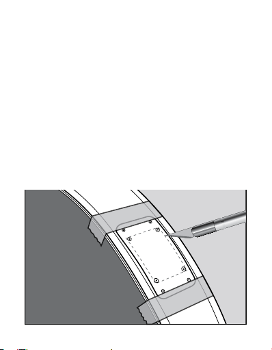
Tape the template to the edge of the instrument, and
mark the center of the circles onto the guitar by tapping through the template into the lacquer using a
center punch and a small hammer. Using an X-Acto
knife, slice through the template along the edges of
the inner rectangle, etching lines in the lacquer to
mark the edges of the mounting hole. Remove the
template and make sure these lines connect in the
corners (this prevents your lacquer from chipping
beyond the scratched lines when you begin drilling).
17
Page 20
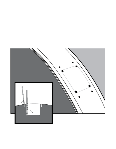
Using a 1/16” bit, drill the four holes for the mount-
90°
90°
ing screws in the outer most marks to a depth of
1/4”. Make these holes perpendicular to the surface. Using the 7/64” bit, drill the inner four marks,
dening the four corners of the mounting hole.
18
Page 21

Using a 5/16” bit, drill holes within the inner rectangle to remove most of the wood in the cavity.
19
Page 22
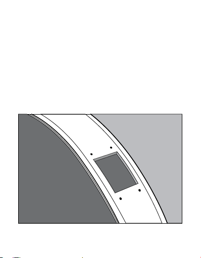
Using a le or a Dremel rotary tool, remove the remaining wood to edges of the marked rectangle. Be careful
not to enlarge the mounting hole beyond the lines, as
the jack plate ts quite precisely to these dimensions.
Remember, this cavity does not have to be neat and
smooth, as it will be hidden completely by the jack plate.
20
Page 23

Mounting the Tone Control
Carefully consider the placement of the Tone Control
module, not only in terms of locating the controls conveniently, but also making sure it will t in the guitar as
you expect. Check before you drill, for braces, kerng, or
other obstructions on the under side of the guitar top.
Variable Control Layouts
The two outer pot shafts are xed to the Tone
Control Module, but the middle pot is on a wiring harness, so it can be positioned as you
like, forming a triangular group of controls.
To achieve an aesthetically pleasing control layout,
remove the nuts and washers from the three pots,
and lay the washers on the guitar top. Slide them
around until they look just right, keeping the outer
two 2-1/2” (63.5mm) apart to mount the Tone Control Module. The placement of the third hole is lim-
21
Page 24

ited by the wiring harness on the middle pot, and
placement of the Tone Control itself. Check inside
the guitar to make sure there are no obstructions,
and that the harnesses to the other components
are long enough to reach. Mark the location of the
holes on the top through the centers of the washers, then remove the washers and set them aside.
Drill three 9/32” (7.1mm) diameter holes to
mount the potentiometers. Two of these holes
must be 2-1/2” (63.5mm) apart, center-tocenter, to accommodate the two pots that
are mounted on the Tone Control’s PC Board.
center-to-center between pots: 2-1/2” (63.5mm)
mounting hole diameter: 9/32” (7.1mm)
22
Page 25

Control Knobs
A set of three, stacked rosewood knobs is available from
Graph Tech as a separate item, with a 1/16” hex key
included for installation. Or you can provide your own
knobs. Secure the knobs onto the pot shafts by means
of the set screws. Leave a little clearance between the
inner and outer knobs so that they turn independently.
Pot Shaft Diameters:
outer, 0.236” (6.0mm); inner, 0.139” (3.5mm)
23
Page 26

J27
J26
J25
J24
J22
E B G D A E
1 2 3 4 5 6
HEXPANDER
+
Wiring Connections Diagram
24
Page 27

Down
Up
Program
9v
Tip
Ring
Y
Vi
Bu
R
R
Bk
+
TONE CONTROL
Treble
Bass
Mid Sweep
Mid Tone
Acoustic
MIDI
Vol.
Vol.
25
Page 28

t e c h n i c a l d e t a i l s
Component Dimensions
Hexpander: 1-3/16” x 2-1/2” (30.2 x 63.5mm)
Tone Control: 1” x 3-1/2” x 5/8” (25.4 x 89 x 15.9mm)
Mounting Hole Diameters
Volume/Tone/Mid-Sweep pots 9/32” (7.1mm)
Program Selector Switch 1/4” (6.4mm)
Output Jack 3/8” (11.9mm)
Part Numbers
BS-0077-00 Pagoda Shim
BN-9277-OE Acoustic Saddles
BD-0477-00 Hexpander
BD-0077-00 OEM Tone Control
BN-0180-00 Program Selector Switch
26
Page 29

i n s t a l l a t i o n n o t e s
27
Page 30

28
n e w s o u n d d i s c o v e r i e s
Page 31

f r i e n d s w h o ’v e g o t t o s e e t h i s ...
29
Page 32

www.graphtech.com
sales@graphtech.com
 Loading...