

Page 1

MT100
MOUNTCORDER
MANUAL NO. MT100-UM-851
Quick Start Guide
Quick Start Guide
English
Page 2

Contents
Introduction 21
To Ensure Safe and Correct Use 21
Checking the Outer Casing 21
Checking the Accessories 21
1. MT100 Part Names and Functions 22
Front 22
Rear 24
2. Installation Procedure 25
3. Connecting to an AC Power Supply 26
4. Connecting Signal Input Cables 27
5. Connecting Cables to Digital Input and Alarm Output Terminals 28
6. Precautions to Observe When Performing Measurement 29
7. Noise Countermeasures 29
8. Initial Setup 30
9. Window names and functions 31
10. Key Operation 33
11. Setting Examples 36
(Example 1) Enabling temperature measurement using thermocouples
for all the channels 36
(Example 2) Storing captured data in USB memory 37
(Example 3) Replaying captured data 38
12. Specifications 39
Page 3

21
Thank you for purchasing the MOUNTCORDER MT100.
Please read this manual and the User's Manual provided in the supplied CD-ROM thoroughly
before attempting to use your new product to ensure that you use it correctly and to its full
To promote safe and accurate use of the MT100 as well as to prevent human injury and property damage,
safety precautions provided in this manual are ranked into the five categories described below. Be sure
you understand the difference between each of the categories.
This category provides information that, if ignored, is
highly likely to cause fatal or serious injury to the operator.
This category provides information that, if ignored, is likely
to cause fatal or serious injury to the operator.
This category provides information that, if ignored, could
cause physical damage to the MT100.
After unpacking, check the MT100's outer casing before use. In particular, please check for the following:
• Surface scratches
• Other flaws such as stains or dirt
After unpacking, check that the following standard accessories are included.
Checking the Accessories
Checking the Outer Casing
DANGER
WARNING
CAUTION
Conventions Used in This Manual
٨To ensure safe and correct use of the MT100, read this Manual thoroughly before use.
٨After having read this Manual, keep it in a handy location for quick reference as needed.
٨Do not permit small children to touch the MT100.
٨The following describes important points for safe operation. Please be sure to observe them strictly.
To Ensure Safe and Correct Use
Introduction
CD-ROM: 1
Panel mount bracket: 2
Quick Start Guide: 1
Page 4

22
1. MT100 Part Names and Functions
Front
Front panel
Monitor
Control panel cover
Opening the Control Panel Cover
As shown in the following figure, hold the tab in the center of the control panel cover and pull it in the
direction indicated by an arrow to open the cover.
Operation status LED
POWER:
ON when the power is ON
START: ON during data capture
Control panel keys
Control panel cover
Page 5

23
Opening the Front Panel
Pull the part indicated by an arrow in the following figure to open the front panel.
Front panel
Power switch
USB memory terminal
Maximum Dimensions of USB Memory
The maximum dimensions of USB memory that can be attached to the MT100 are shown in the following
figure.
Front
47mm
90mm
21.5mm
13mm
8.5mm
Page 6

24
Rear
Power terminal and protective ground
terminal
USB terminal
Ethernet terminal
Power jack for the humidity sensor
External input/output
terminal
LOGIC/PULSE
EXT TRIG
ALARM
Analog signal input
terminals
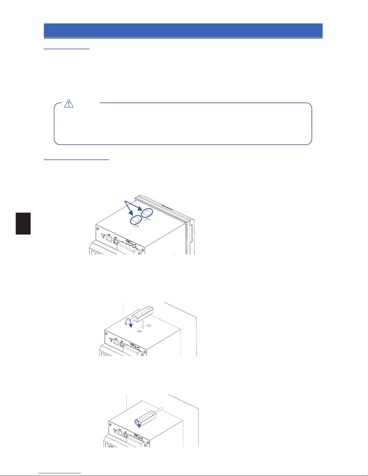
Removing the Terminal Cover
While applying force in direction A, pull the cover in direction B to remove the cover.
(The external input/output terminal cover can also be removed in the same way.)
A
B
Page 7
25
ii
i
CAUTION
Installation Site
2. Installation Procedure
Install the MT100 in an indoor location where:
an instrumentation panel can be attached
For information on the panel cut dimensions, see the User's Manual in the supplied CD-ROM.
there is good ventilation
there is little mechanical vibration
the floor is level
Do not install the MT100 in a location where:
㨯 the unit is exposed to direct sunlight or near a heater.
㨯 there are excessive greasy fumes, steam, humidity, dust, corrosive gas, etc.
㨯 the unit is near an electromagnetic field source.
As the panel, use a steel sheet 2mm to 26mm in thickness. Use the panel mount brackets provided with the MT100 to attach it.
There are two panel mount brackets. Be sure to attach them in two opposite locations (up and down or left and right).
Installation Procedure
ԘޓPeel off the masking tape from the surface on which you want to attach a panel mount bracket.
ԙޓInsert the MT100 from the front side of the panel.
ԚޓAttach the MT100 to the panel using the provided mount bracket as shown in the figure below.
i. Use two mount brackets on the up and down or left and right of the case.
(Peel off the masking tape on the case that covers the holes for mount brackets beforehand.)
ii. Attach the two brackets first, then temporarily tighten mounting screws on them.
ԛޓTighten the screws to an appropriate torque.
Next, tighten the mounting screws to an appropriate torque to fix the main unit. While keeping the
main unit roughly at right angles to the panel, bring the mounting bracket into close contact with the
main unit case and tighten the mounting screws.
* The appropriate tightening torque of panel mounting screws is 10 to 12kgf/cm.
Peel off the masking tape.
Page 8

26
Rated power voltage
Power supply voltage range
Rated power frequency
Power frequency tolerance
Maximum power consumption
Item
100 to 240VAC
90 to 264VAC
50/60Hz
50/60Hz±2%
38VA
Specification
WARNING
3. Connecting to an AC Power Supply
No power cord is supplied with the MT100.
Be sure to use a power cord supplied with the optional desktop case (B-541).
Connecting Cables
ԘޓTurn off the power supplied to the MT100 and open the power terminal cover (transparent).
ԙޓConnect the power cord and the protective ground cord to the power terminals.
Use non-insulated solderless ring terminals (for 4mm screws) and insulation caps.
The appropriate tightening torque of screws is 12 to 14kgf/cm.
ԚޓClose the power terminal cover (transparent) and fix it with screws.
ԛޓOpen the front panel and turn on the power switch to power on the MT100.
Remove these two screws to remove the power terminal cover.
Protective ground terminal
Functional ground
terminal
Protective ground cord
Power cords
Non-insulated
solderless ring
terminals
(for 4mm screws)
Insulation caps
ޓ
ޓ
ޓ
ޓ
ޓ
ޓ
ޓ
To avoid electric shocks, check that the AC source for the power supply has been turned off.
To prevent fire, use wires or cables with a performance equivalent to or better than 600V insulated wires
(AWG 20 to 16).
Before turning on the power, be sure to connect the protective ground terminal to the ground at a
grounding resistance of 50ǡ or less.
For cables to be connected to a power supply and a protective ground terminal, use non-insulated
solderless ring terminals (for 4mm screws) inserted in insulation caps.
In the power line, provide a switch that can cut off the MT100 from the main power source (double-pole type).
As specifications of the switch, the rated steady-state current must be 1A or larger and the rated
inrush current must be 60A or larger.
Do not insert a switch or fuse in a grounding line.
Use a power supply that meets the following conditions.
Page 9

27
㨎
㨎
㧭
㧮
㨎
㨎
㨎
WARNING
CAUTION
4. Connecting Signal Input Cables
This section describes how to connect the signal input cables.
To avoid electric shocks, check that the AC source for the power supply has been turned off before connecting
A large pulling force applied to an input/output signal cable connected to the MT100 may damage a
terminal or the signal cable. Therefore, fix the wiring cords to the back of the installed panel.
To prevent fire, use signal cables with a rated temperature of 70°Cor higher.
Do not apply a voltage higher than the following values to input terminals. If you do, the MT100 may
suffer damages.
Maximum input voltage: ±60VDC
Maximum common-mode voltage: AC33Vrms or ±60VDC
Caution on Connecting Cables
Connecting Cables
ԘޓRemove the terminal cover.
ԙޓConnect signal cables to the input terminals.
The appropriate tightening torque of screws is 12 to 14kgf/cm.
Connect wires to terminals as shown in the following figure after checking them.
ԚޓReinstall the terminal cover.
Connection diagram
Direct voltage
٨Direct voltage input
٨Thermocouple input
Compensation copper wire
٨Resistance temperature detector input
٨Direct current input
Direct current
Connect input signal cables to terminals using insulated solderless terminals (for 4mm screws).
Keep the measuring circuit away from a power cable (power circuit) or a ground circuit.
If the measuring target is a noise source, refer to page 29 and take a necessary measure.
Be sure to connect a protective ground terminal to the ground at a low grounding resistance (50ǡ or less).
Be sure to attach a terminal cover when you measure temperatures using a thermocouple.
Do not use a thick wire with a high heat radiation effect when you measure a temperature using a
ޓthermocouple (a wire having a diameter of 0.65mm or less is recommended).
Avoid causing changes in the outside air temperature. In particular, turning on and off the fan near the
ޓMT100 causes significant temperature changes.
If an input cable is connected in parallel with another device, the measurement values of both the
ޓMT100 and the device may be influenced.
Do not turn on and off one of the devices during operation. The other device may be adversely
ޓinfluenced.
Page 10

28
+5V +5V
PULSE/LOGIC(n)
GND
+5V
+5V
EXT TRIG
GND
ALARM(n)
NC
COM
NO
Comparator
Comparator
WARNING
CAUTION
5. Connecting Cables to Digital Input and Alarm Output Terminals
This section describes how to connect the signal input/output cables.
To avoid electric shocks, check that the AC source for the power supply has been turned off before connecting cables.
A large pulling force applied to an input/output signal cable connected to the MT100 may damage a
terminal or the signal cable. Therefore, fix the wiring cords to the back of the installed panel.
To prevent fire, use signal cables with a rated temperature of 70°C or higher.
Do not apply a voltage higher than the following values to input terminals. If you do, the MT100 may
suffer damages.
Digital signal terminal: +24VDC at the maximum
Alarm output relay terminal: 250VAC/2A, 30VDC/2A
Caution on Connecting Cables
Connecting Cables
ԘޓRemove the terminal cover.
ԙޓConnect signal cables to the input terminals.
The appropriate tightening torque of screws is 12 to 14kgf/cm.
Connect wires to terminals as shown in the following figure after checking them.
ԚޓReinstall the terminal cover.
Pulse/logic input
Trigger input
Alarm output
* When an alarm is generated, COM and NO are connected (while COM and NC are open-circuited).
Internal equivalent circuit of input/output circuit
When you connect digital input and alarm output cables, please note the following:
Use insulated solderless terminals (for 4mm screws) to connect signal cables to terminals.
Connect a protective ground terminal to the ground at a low grounding resistance (50ǡ or less).
Page 11

29
DANGER
CAUTION
Channel Switching Relay
6. Precautions to Observe When Performing Measurement
Please be sure to read the following carefully in order to prevent electric shocks or shorts.
• Do not apply voltage of AC30Vrms or 60VDC or above between the analog input section and main unit
(GND terminal), or between each analog input channel.
• Do not apply radio-frequency signals with high voltage (50KHz or above).
Input Circuit Diagram for Analog Input (Voltage, Thermocouples)
Capacitors have been incorporated into the input circuit to increase the noise elimination capability.
After voltage measurement, when the inputs have been disconnected, there will still be some electric
charge remaining. Before starting another measurement operation, short-circuit the + and - terminals to
enable self-discharge.
The MT100 has a scan system.
While in the status (open) in which signals are not input to the input terminal, measured results may be
influenced by signals from other channels.
In such a case, turn OFF the input setting or short circuit +/-.
If signals are input correctly, measured results are not influenced by other channels.
7. Noise Countermeasures
If the measurement values of the MT100 vary due to external noise, the following countermeasure is recommended.
(The effect varies depending on the noise type.)
Example 1: Connect the ground terminal of the MT100 to the ground (see the following figure).
Example 2: Connect the ground terminal of the MT100 and the ground terminal of a measurement
target (see the following figure).
Example 3: Set the filter to other setting than OFF in the AMP setup menu.
Example 4: Set a sampling interval at which the digital filter of the MT100 is effective (500ms or more).
To be connected to the
power ground
(Protective grounding)
To be connected to the chassis of the
measuring target (Functional grounding)
Page 12

30
CAUTION
8. Initial Setup
Language Setting
When you power on the MT100 for the first time after purchase, a language selection menu is displayed.
Select a language that you want to use.
The language setting can be changed later.
To change the setting later, open OTHR menu and select Language.
If you are using the MT100 for the first time, charge the internal rechargeable battery and then make the
date and time settings.
Setting the Date and Time
If the MT100 is not used for a period of approximately six months, the internal rechargeable battery may
be discharged and the date and time may revert to the initial settings. If this happens, recharge the
battery before using the MT100.
How to Recharge the Rechargeable Battery
Turn on the power switch and leave the MT100 connected for at least 24 hours.
How to Set the Date and Time
Press the MENU key, display the OTHR screen, and then set the date and time at the Date/Time Settings
sub-menu. Refer to the User's Manual in the supplied CD-ROM for more information on the setting.
Page 13

31
CAUTION
9. Window names and functions
Status display
Screen
Measurement data display
Status display
Ԙ Simplified message display
ԙ Time/DIV display Ԛ
Status display
ԛ Clock display
Ԝ
Alarm display
Displays the operation status of the MT100.
Free Running : Displayed in the start-up status or when no data is being captured.
Armed :
Displayed when the MT100 is waiting for a trigger to be issued after
measurement is started (No data is being captured).
Memory Recording :
Displayed when data is being captured to the internal memory of the MT100.
USB Drv Recording : Displayed when data is being captured to the USB memory.
Memory Review :
Displayed when data is being replayed from the internal memory of the MT100.
USB Drive Review : Displayed when data is being replayed from the USB memory.
ԘޓSimplified message display
ԙޓTime/DIV display
Displays the current time scale.
Displays the current date and time.
Displays the alarm output terminal status. The terminal for which an alarm has been generated has a
terminal number displayed in red.
ԚޓStatus display
USB memory status display
: (Gray) No USB memory is attached.
: (Green) USB memory is attached but not being accessed.
: (Red) USB memory is being accessed.
: (Gray) Keys are not locked. Normal operation is enabled.
: (Yellow) Keys are locked. All the keys are locked.
Refer to the User's Manual provided with the MT100 for more information on the key lock statuses.
: (Gray) Local mode. The operations on the MT100 are enabled.
: (Yellow)
Remote mode. The operations on the PC are enabled except for some operations.
Cancel the PC connection to automatically return from the remote mode to the local mode.
If the local mode is not regained, press the QUIT key.
: (Gray) Internal memory is not accessed.
: (Red) Internal memory is being accessed.
Internal memory status
Do not turn off the power of the MT100 while the USB memory or internal memory is being accessed.
If you do, data may be corrupted and you may no longer be able to access the memory.
Key lock status display
Remote mode display
ԛޓClock display
ԜޓAlarm display
<Waveform scrolling direction: Vertical>
<Waveform scrolling direction: Horizontal>
Page 14

32
<Waveform scrolling direction: Vertical >
<Waveform scrolling direction: Horizontal >
Measurement data display
ԘData capture bar
ԙDigital display
ԚPen display
ԛ
Waveform display (Present)
Ԝ
Compressed waveform display (Past)
ԝSampling interval display
ԞFile name display
Displays the position of each channel signal with the pen.
In addition, displays the trigger position and the alarm range.
ԚޓPen display
Displays measurement signals as waveforms in real time.
ԛޓWaveform display (Present)
Displays the current sampling interval.
ԝޓSampling interval display
Displays the name of the file used to capture data.
(Displayed only while data is being captured.)
ԞޓFile name display
Displays measurement signals in compressed format.
The compression rate can be set using the menu.
Refer to the User's Manual in the supplied CD-ROM for more information on the setting.
ԜޓCompressed waveform display (Past)
Displays the input value of each channel.
Use the SPAN/TRACE/POSITION key to check the setting value of each channel.
ԙޓDigital display
During data capture, indicates capturing time and the remaining capacity of the capture media.
(When the remaining capacity runs short, the display changes into orange.)
During replay, indicates information about the displayed position.
ԘޓData capture bar
Trigger level display
ޓDisplays the trigger level position and direction.
* Displays the trigger level also in horizontal scrolling.
Alarm range display
ޓDisplays the alarm position and range.
ޓAn alarm is generated when a signal enters the green area shown in the following figure.
ޓ(When an alarm is generated, the display changes into red.)
* Displays the alarm range also in horizontal scrolling.
<H> <L> <Win In> <Win Out>
Page 15

33
10. Key Operation
(1) CURSOR
(2) SPAN/TRACE/POSITION
(3) QUIT
(4) Direction Keys
(5) MENU
(6) START/STOP
(7) ENTER
(8) DISPLAY
(9) TIME/DIV
(10) REVIEW
This key has different roles according to the operation status.
During replay: This key is used to toggle between cursors A and B displayed during replay.
During free-running and data capture: When the alarm setting is “Hold generated Alarm”, the
maintained alarm is cleared.
(1) CURSOR (ALM CLR)
Pressing this key can switch the channels of the digital display area.
Used to change the settings related to waveform display during free running (when stopped), data
capture and data replay.
(2) SPAN/TRACE/POSITION
This key is primarily used for the following operations.
To cancel a setting during menu configuration.
To return to the MONITOR window when the SPAN/TRACE/POSITION window is displayed.
To cancel remote status (in which keys are disabled) through interface control.
To close the menu screen.
To quit data replay.
To return from the Digital + Calculation Display or Bar Graph Display to Waveform + Digital Display
(3) QUIT (LOCAL)
MONITOR
Displays the measurement values of each
channel.
(Default)
SPAN
Allows changing of the span value.
Channel change: keys
Span change: keys
Change range: Eight voltage levels
and six temperature levels
POSITION
Allows changing of the waveform position.
Channel change: keys
Position change: keys
Change range: Range can be
changed in units of 10%.
TRACE
Allows turning ON/OFF of the waveform
display.
Channel change: keys
Trace change: keys
Change range: ON/OFF
* Data capture is enabled even with the
OFF setting.
[SPAN/TRACE/POSITIO N] key
[SPAN/TRACE/POSITIO N] key
[SPAN/TRACE/POSITIO N] key
[SPAN/TRACE/POSITIO N] key
Page 16

34
CAUTION
This key is primarily used for the following operations.
To move a menu or setting item during menu configuration.
To move the cursor during replay.
To move the active channel in the Waveform + Digital screen ( keys).
To change the setting of SPAN/TRACE/POSITION ( keys).
(4) Direction keys
Open the settings window to capture data. Pressing this key switches the tab on the settings window.
Refer to the User's Manual in the supplied CD-ROM for more information on the setting.
(5) MENU
This key is used in the following two operations:
<Starting or Stopping Measurement>
Pressing this key during free-running starts capture.
Pressing this key during capture stops capture.
<USB Drive Mode>
In USB Drive Mode, the internal memory is recognized by the PC as external storage media.
Files on the internal memory, being recognized as a removable disk, can be easily transferred, deleted, or otherwise handled.
ԘޓUse a USB cable to connect the MT100 and a PC.
ԙޓWhile pressing the MT100 START/STOP key, turn the power ON.
ԚޓThe external storage media is recognized by the PC and data exchange becomes possible.
(The screen is shown in the following figure.)
(6) START/STOP(USB DRIVE)
This key is used to finalize setting items during menu configuration or open submenus.
(7) ENTER
AMP
DATA
TRIG
DISP
MARK
FILE
USER
I/F
OTHR
Specify input signal-related settings.
Input, range, filter, etc.
Specify miscellaneous settings.
LCD brightness, language, AC line frequency, etc.
Specify capture-related settings.
Sampling interval, file name, statistical calculation, etc.
Specify trigger and alarm settings.
Capture start and stop conditions, alarm conditions, etc.
Specify screen display settings.
Scrolling direction, waveform color, etc.
Specify mark-related settings.
Mark text setting, mark display execution, etc.
Specify file-related settings.
Setting conditions, bitmap, file operations, etc.
Specify setting conditions for each user of the MT100.
User name, user switching, etc.
Specify interface-related settings.
USB ID number, LAN IP address, etc.
To exit USB Drive Mode, turn the power off and then on.
When the MT100 is used in USB Drive Mode, no user operation
ޓis allowed, including data capturing and data replay.
Page 17

35
This key is used to switch the data display mode.
You can switch the display mode during free running (when stopped) and data capturing.
Pressing this key switches the display mode as follows:
(8) DISPLAY
Pressing this key changes the time axis display width.
The following settings are possible.
1, 2, 5, 10, 20, 30sec/DIV
1, 2, 5, 10, 20, 30min/DIV
1, 2, 5, 10, 12, 24, 72 hour/DIV
(9) TIME/DIV
This key is used to replay captured data.
(10) REVIEW
Waveform + Digital Screen
Displays waveforms and digital values.
This is the initialscreen at power-on.
Digital + Calculation Display screen
Displays digital values and calculation results in large
text.
Calculation results are added up in real time.
Refer to the User's Manual in the supplied CD-ROM
for more information on the calculation results.
Bar Graph screen
Displays measurement data in bar graphs.
Allows you to select a reference point of a bar graph.
Refer to the User's Manual in the supplied CD-ROM
for more information on the setting.
Page 18

36
11. Setting Examples
(Example 1) Enabling temperature measurement using thermocouples for all the channels
ԘޓPress the MENU key to open the AMP menu.
ԙޓUse the key to move the cursor to ALL Input.
ԚޓPress the ENTER key to select TEMP.
Ԝޓ
Press the ENTER key to select a thermocouple type.
ԝޓPress the MENU key to open the DATA menu.
ԞޓPress the key to move the cursor to Sampling.
ԟޓ
Press the ENTER key to set the sampling interval to 1s.
ԛޓPress the key to select ALL Range.
A sampling interval of 1 sec or more is recommended to improve the
efficiency of removing external noise.
Page 19

37
(Example 2) Storing captured data in USB memory
This setting allows you to store captured data with an automatically generated file name in USB memory.
* Attach the USB memory to the MT100 before making this setting.
ԘޓPress the MENU key to open the DATA menu.
ԙޓUse the key to select File Name
ޓޓand press the ENTER key.
ԚޓSelect Folder and press the ENTER key.
ԛޓUse the key to move the cursor to USB1
ޓޓand press ENTER.
ԜޓUse the key to select OK and press
ޓޓthe ENTER key.
Page 20

38
(Example 3) Replaying captured data
This section explains how to replay captured data.
ԘޓPress the REVIEW key to open the Data Replay
Source menu.
ԙޓSelect File and press the ENTER key to open the
file selection menu.
ԛޓSelect a file to be replayed and press the ENTER
key.
ԜޓMove the cursor to OK and press the ENTER key.
ԚޓPress the key to go into a folder.
Press the and keys to move the cursor and
check the measurement values.
Press the CURSOR key to switch between
Cursors A and B.
Page 21

39
12. Specifications
Standard Specifications
Interface specifications
Sampling interval
TIME/DIV
Data save functions
(internal and USB memory)
Calculation
Display modes
Message/marker function
Clock accuracy (23°C environment)
Insulation resistance
Data backup functions
Withstand voltage
Number of analog input
External input/output
PC interface
Internal memory devices
Operating environment
Power supply
Internal memory: approx. 14MB
USB memory slot (FullSpeed supported) is provided as a standard feature
100, 125, 200, 250, 500ms, 1, 2, 5, 10, 20, 30sec, 1, 2, 5, 10, 20, 30min, 1 hour
1, 2, 5, 10, 20, 30 sec/DIV, 1, 2, 5, 10, 20, 30min/DIV, 1, 2, 5, 10, 12, 24, 72 hour/DIV
Save data: Measurement data, setup data, copy of data screen
Backup function: Internal to USB memory; internal to FTP server; USB memory to FTP server
* USB memory can be removed during data capture.
Types of statistical calculation: Average value, peak value, maximum value, minimum value, RMS
Calculation between channels: Addition, subtraction, multiplication, and division; calculation of humidity from wet and dry bulb temperature (Channels 1 and 2 only)
Waveform + digital (vertical and horizontal scrolling), digital, and bar graph
Function: Records message/marker at specified timing
Number of registered messages: 8
Marker type: Arbitrary message, start/stop, trigger, alarm, power failure
Setup conditions: EEPROM; Clock: lithium secondary battery
0 to 50°C, 5 to 85%RH
Between AC input and GND: 1 minute at 2000VAC
Between alarm terminal and GND: 1 minute at 1000VAC
Between each input channel and GND: 1 minute at 350Vp-p
Between input terminals: 1 minute at 350Vp-p
AC input: 100 to 240VAC/50 to 60Hz
Terminal type: M4 screw type terminals
Description
1 unit (10 channels)
Trigger input, Logic input 4 channels or Pulse input 4 channels, Alarm output
Ethernet (10BASE-T/100BASE-TX), USB (FullSpeed supported) provided as standard features
r
0.002% (approx. 50 seconds per month)
٨
AC power consumption
H144 x W144 x D200mm
Condition
2.1kg
Equivalent to automobile parts Type 1 Category A classification
When the LCD is ON
When the screensaver is operating
Vibration-tested conditions
Weight
Other
Power consumption
1
2
* Normal status is when LCD brightness is set to MAX.
No.
IP-65 compatible (only the front panel)
38VA
30VA
Dust-proof and water-proof
External dimensions
Interface types Ethernet (10BASE-T/100BASE-TX)
USB (FullSpeed)
Ethernet functions Web server function: Displays MT100's screen image on Web browser, operation of MT100
(10BASE-T/100BASE-TX) FTP server function: Transfers and deletes files from internal memory and USB memory
FTP client function: Supports backup of data in internal and USB memory
NTP client function: Adjusts internal clock
USB functions USB drive mode: Transfers and deletes files from internal memory
Realtime data transfer speed 100 msec/10 ch maximum
Item
Input/output types • Trigger input (1 ch) • Logic input (4 ch) or Pulse input (4 ch) • Alarm output (4 ch)
* Switch between Logic and Pulse
Input specifications Maximum input voltage: 0 to +24V (single-ended ground input)
Input threshold voltage: Approx. +2.5V
Hysteresis: Approx. 0.5V (+2.5 to +3V)
Alarm output specifications
Output format: Relay contact output (NO/NC)
Rated: 250VAC/2A
Item Description
Item
Description
Digital input specifications
Between AC input and GND: 20Mǡ or higher (500VDC)
Between alarm terminal and GND: 50Mǡ or higher (500VDC)
Between each input channel and GND: 50Mǡ or higher (500VDC)
Page 22

40
Input unit specifications:
Item Description
Number of input channels
Input terminal type
Input method
Scan speed
Measurement
ranges
Voltage
Temperature
Humidity
Measurement
accuracy*1
(23°C
r5°C㧕
Voltage
Temperature
10 ch
M4 screw type terminals
Photo MOS relay scanning system
All channels isolated, balanced input
0.1s/10 ch maximum
20, 50, 100, 200, 500mV; 1, 2, 5, 10, 20, 50V; 1-5 V F.S.
0 to 100% (voltage 0V to 1V scaling conversion) *with B-530 (option)
0.1% of F.S.
٨Thermocouple
*2
Type Measurement Temperature Range Measurement Accuracy
Reference contact compensation accuracy
R/S
B
K
E
T
J
N
W
r5.2°C
r3.0°C
r(0.05% of rdg +2.0°C)
r(0.05% of rdg +2.0°C)
r3.5
r(0.05% of rdg +2.0°C)
r(0.05% of rdg +2.0°C)
r(0.05% of rdg +1.0°C)
r(0.05% of rdg +2.0°C)
r(0.05% of rdg +1.0°C)
r(0.1% of rdg +1.5°C)
r(0.1% of rdg +0.5°C)
r2.7°C
r1.7°C
r(0.05% of rdg +1.0°C)
r(0.1% of rdg +1.0°C)
r(0.1% of rdg +1.5°C)
r0.5°C
٨Resistance temperature detector
Type Measurement AccuracyApplied current Measurement Temperature Range
Pt100 -200 to 850°C (FS=1050°C)
JPt100 -200 to 500°C (FS=700°C)
Pt1000 -200 to 500°C (FS=700°C)
1mA r(0.05% of rdg +0.5°C)
1mA
0.2mA
r(0.05% of rdg +0.5°C)
r(0.05% of rdg +0.5°C)
Reference contact compensation accuracy
A/D converter
Temperature coefficient
Input resistance
Allowable signal source resistance
Maximum permissible
input voltage
Withstand voltage
Insulation resistance
Common mode rejection ratio
Noise
Filter
Internal/External switching
16 bits (out of which 14 bits are internally acknowledged)
Gain: 0.01% of F.S./°C
Between +/– terminals: 60Vp-p
Between input terminal/input terminal: 60Vp-p
Between input terminal/GND: 60Vp-p
Between input terminal/input terminal: 1 minute at 350Vp-p
Between input terminal/GND: 1 minute at 350Vp-p
At least 48dB (with +/– terminals shorted)
Off, 2, 5, 10, 20, 40
Filter operation is on a moving average basis.
The average value of the set sampling count is used.
*1
When 30 minutes or more
ޓhave elapsed after power
ޓwas switched on
Sampling 1s
Filter ON (10)
GND connected
0 ҇Ts ҇ 100
100 㧨 Ts ҇300
R: 300 㧨 Ts ҇ 1600
S: 300 㧨 Ts ҇ 1760
400 ҇ Ts ҇ 600
600 㧨 Ts ҇ 1820
㧙200 ҇ Ts ҇ 㧙100
㧙100 㧨 Ts ҇ 1370
㧙200 ҇ Ts ҇ 㧙100
㧙100 㧨 Ts ҇ 800
㧙200 ҇ Ts ҇ 㧙100
㧙100 㧨 Ts ҇ 400
㧙200 ҇ Ts ҇ 㧙100
㧙100 㧨 Ts ҇ 100
100 㧨 Ts ҇ 110 0
0 ҇ Ts ҇ 1300
0 ҇ Ts ҇ 2000
Thermocouples: K, J, E, T, R, S, B, N, W (WRe5-26)
Resistance temperature detector: Pt100, JPt100, Pt1000 (IEC751)
1Mǡ r5%
Within 300ǡ
Between input terminal/GND: At least 50Mǡ (at 500VDC)
At least 90dB (50/60Hz; signal source 300ǡ or less)
*2: Thermocouple diameters T: 0.32Ǿ , others: 0.65Ǿ
 Loading...