

Page 1

JW220-06
USER’S MANUAL
MANUAL NO.JW220-UM-151
Page 2

TO ENSURE SAFE AND CORRECT USE
• To ensure the safe and correct use of your printer, read this manual thoroughly prior to
use.
• After reading this manual, store it in a safe place for reference as necessary.
• Do not allow small children to touch the printer.
• The following describes important points for safe operation. Be sure to observe them
strictly.
Conventions Used in This Manual
To ensure the safe and correct use of the printer as well as to prevent human injury and
property damage, the safety precautions provided in this manual are ranked in the three
categories described below. Be sure to gain a full understanding of the difference
between each of the categories before reading the Manual.
This category provides information that, if ignored, is highly likely
DANGER
WARNING
to cause fatal or serious injury to the operator.
This category provides information that, if ignored, is likely to
cause fatal or serious injury to the operator.
This category provides information that, if ignored, could cause
CAUTION
injury to the operator or damage to the printer.
Description of Safety Symbols
The symbol indicates information that requires careful attention (including warnings). The specific point requiring attention is
described by an illustration or text within or next to the symbol.
The symbol indicates an action that is prohibited. Such prohibited action is described by an illustration or text within or next to
the symbol.
The symbol indicates an action that must be performed. Such
imperative action is described by an illustration or text within or
next to the symbol.
i
Page 3

Safety Precautions
To ensure the safe and correct use of your printer, be sure to observe the following
points.
Installation Precautions
WARNING
Do not install the printer in the vicinity of
volatile solvents such as alcohol or thinner.
• A volatile solvent coming into contact with any of the
internal electrical components may result in a fire
hazard or electric shock.
Benzine
Thinner
Do not place objects such as those listed
below on top of the printer.
• Objects such as these coming into contact with any
of the internal electrical components may result in a
fire hazard or electric shock.
- Metallic objects such as necklaces
- Objects such as glasses, vases, houseplants, etc. that contain water or other fluids
If any of these objects does come into contact with the internal electrical components
immediately turn off the power, remove the plug from the power outlet, and either
contact the store where you purchased your printer or your nearest Graphtec representative.
CAUTION
Do not use the printer in an unstable location
such as on a slope or a location that is subject
to a lot of vibration.
• Such locations may cause the printer to tip over and
cause injuries.
Do not place heavy objects on top of the
printer.
• Such objects may tip over or fall off, causing injuries.
ii
Page 4

If the printer is mounted on its dedicated
stand, be sure to use the caster stoppers to fix
the stand in place and prevent it from moving
while the printer is being used.
• If the stand is not fixed in place, the printer may tip
over and cause injuries.
Avoid using the printer in the following loca-
tions.
• Use in such locations may result in a fire hazard or
electric shock.
- Excessively humid or dusty locations
- Locations exposed to direct sunlight
- Locations exposed to high temperatures
- Locations near flames or moisture
iii
Page 5
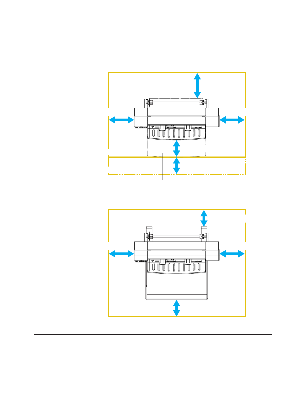
Leave plenty of space around the printer.
• Leave sufficient space for operations in front of and
behind the printer.
When using the printer on a desktop
At least 300 mm
At least 300 mm
Standard
When the paper guide table is mounted
When the A2-size paper feed cassette is mounted.
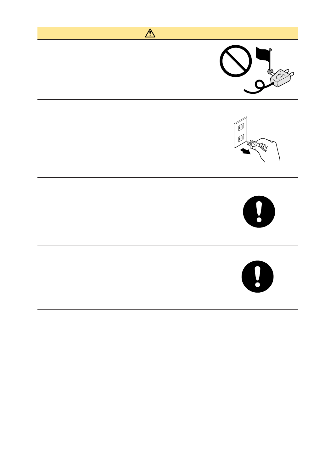
When using the printer on its optional stand
At least 300 mm
At least 300 mm
At least 200 mm
At least 200 mm
A2-size paper feed cassette
At least 200 mm
At least 300 mm
At least 200 mm
iv
Page 6

Power Supply Precautions
WARNING
Do not damage the power cable, or modify it in
any way. Moreover, do not place heavy objects
on the power cable, pull on the cable, or bend
it excessively.
• There may be current leakage from the damaged
parts, resulting in a fire hazard or electric shock.
• Do not unplug or plug in the power cable when your
hands are wet, such action may result in electric
shock.
Do not connect multiple devices to the same
power outlet.
• Use of the printer in such a condition may result in a
fire hazard or electric shock.
Do not bundle or tie-wrap the power cable.
• Use of a bundled power cable may result in a fire
hazard or electric shock.
Make sure that the power cable is firmly in-
serted into the power outlet.
• Use of a power cable when the plug is not completely inserted into the power outlet may result in a
fire hazard or electric shock.
Do not use a power cable other than the one
supplied with your printer.
• Use of a different power cable may result in a fire
hazard or electric shock.
v
Page 7
CAUTION
Do not connect the inkjet printer to a non-rated
power supply.
• Use of a different supply voltage may result in
electrical shock or a fire hazard due to current
leakage.
When disconnecting the power cable, be sure
to hold on to the plug, and not pull on the
cable itself.
• Pulling on the cable will expose the core wires, or
cause damage such as broken wires. Current
leakage from the exposed or damaged areas may
result in a fire hazard or electric shock.
As a general rule, do not use an extension
cord.
• Use of an extension cord may result in a fire hazard
or electric shock. If you must use an extension cord,
unbundle it, and make sure that the power plug is
firmly inserted into the extension cord socket.
Prohibited
Specified
rating
Make sure that the power plug can be readily
unplugged at any time, and that there are no
objects placed in its vicinity.
• Objects placed in the vicinity of the power plug will
prevent its removal in an emergency.
vi
Page 8

Be sure to ground the earth terminal.
Ground the inkjet printer
• If the cutting plotter is not grounded, the operator
could suffer an electrical shock in case of current
leakage.
• Denmark
Vigtigt ! Lederen med grøn/gul isolation må kun tilsluttes en
klemme mærket (IEC 417, No. 5019) eller (IEC 417, No. 5017).
• Norway
Apparatet må tilkoples jordet stikkontakt.
• Sweden
Apparaten skall anslutas till jordat uttag.
• Finland
Laite on liitettävä suojamaadoituskoskettimilla varustettuun pistorasiaan.
Handling Precautions
WARNING
Do not disassemble or modify the printer.
• Such actions may result in a fire hazard or electric
shock.
If the printer makes an unusual noise, gener-
ates smoke, overheats, emits a strange odor,
or otherwise functions abnormally, immedi-
ately turn off the power, remove the plug from
the power outlet, and either contact the store
where you purchased your printer or your
nearest Graphtec representative.
• Use of the printer in such a condition may result in a
fire hazard or electric shock.
Do not use flammable aerosols or similar
products in the vicinity of the printer.
• The gas contained in the spray may cause a fire
hazard or electric shock if it comes into contact with
the printer's internal electrical components.
vii
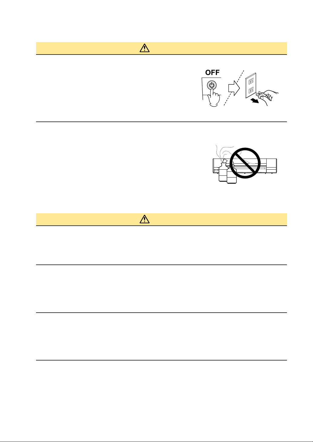
Page 9

Before moving the printer, make sure that the
power switch is in the "off" position and that
the power plug has been removed from the
power outlet.
• If the printer is moved while it is still plugged into the power outlet, the power cable may
be damaged and cause a fire hazard or electric shock.
CAUTION
Take care not to drop metallic items such as
paper clips or staples, or spill water, other
fluids or flammable solvents (alcohol, ben-
zene, thinner, etc.) inside the printer.
• Metallic items or fluids coming into contact with the
internal electrical components may result in a fire hazard or electric shock. If such items
or fluids fall or are spilled inside the printer, immediately turn off the power, remove the
power plug from the power outlet and either contact the store where you purchased the
printer or your nearest Graphtec representative.
Do not insert your hands inside the printer
during a printing operation or when paper is
being loaded.
• Moving parts inside the printer may cause injuries.
Take care not to cut your hands or other parts
of your body when handling the roll paper
cutter.
• There is a risk of cutting your fingers on the cutter
blade.
If the printer will not be used for an extended
length of time, such as at night, turn off the
power switch as a safety precaution.
viii
Page 10
Maintenance and Inspection Precautions
WARNING
Be sure to turn off the power and remove the
power plug from the power outlet before per-
forming any cleaning operations.
• Failure to do so may result in a fire hazard or electric shock. Moreover, there is a risk of injury if the
printer starts to move during a cleaning operation.
To clean the printer, use a cloth that has been
dampened with neutral detergent and then well
wrung out. Do not use volatile solvents such
as alcohol, benzene or thinner to clean the
printer.
• A volatile solvent coming into contact with any of the
internal electrical components may result in a fire
hazard or electric shock.
Benzine
Thinner
CAUTION
At least once a year, remove the power plug from the power outlet and clean
the prongs and surrounding areas.
• A build-up of dust may result in a fire hazard.
When cleaning or checking the inside of the printer, make sure that a
metallic object such as a necklace or bracelet does not come into contact
with any of the internal components.
• Such actions may result in injuries or an electric shock.
When replacing roll paper, loading paper, or removing paper that has
become jammed in the printer, take care not to cut yourself on the edges
of the paper.
• Sharp paper edges may cause injuries.
ix
Page 11

Precautions on Handling the Consumable Items
CAUTION
Do not touch any metallic parts on the print
heads after a printing operation.
• These parts will be hot, and may cause burns.
• Printing malfunctions may occur.
• There is a risk of damage from static electricity.
Do not touch the ink cartridge openings or the
head section of the print heads.
• Your fingers may become stained with ink.
• Printing malfunctions may occur.
• There is a risk of damage from static electricity.
As a safety precaution, store the print heads and ink cartridges in a location
out of the reach of small children.
• If ink is licked or ingested accidentally, consult a doctor immediately.
Do not drop or shake the print heads or ink
cartridges.
• Such actions may cause the ink to leak or spatter,
with the risk of staining your surroundings and
clothing.
• The head section may become damaged, making
the print head unusable.
Do not touch the blade of the roll paper cutter.
• You may cut your fingers on the blade.
The print heads are consumable items
• The print heads are consumable items. If printing is not performed correctly even after
the print heads have been cleaned or adjusted, replace them with new ones. See
Chapter 5, "Maintenance" for further details.
x
Page 12
Precautions to observe when removing jammed paper
• When removing paper that has become jammed inside the printer, take care not to get
ink from the paper on your clothing or hands. There is a possibility of ink adhering to
your clothing or hands.
• If paper has become jammed during a paper feed operation, do not pull too hard on
the paper to remove it. Pulling on the paper may cause it to tear, and torn paper
fragments remaining inside the printer may cause paper feed problems.
• Please refer to Section 6.4, "If the Paper Becomes Jammed" for the correct removal
procedure.
Precautions to Note When Unpacking the Printer
If the printer was stored in a location where the temperature dropped below 10 °C,
allow sufficient time for the printer to become acclimatized to room temperature (the
operating environment specification is the range from 15 °C to 30 °C) before mounting
the print heads. (We recommend that you allow at least two hours for the printer to
become acclimatized.)
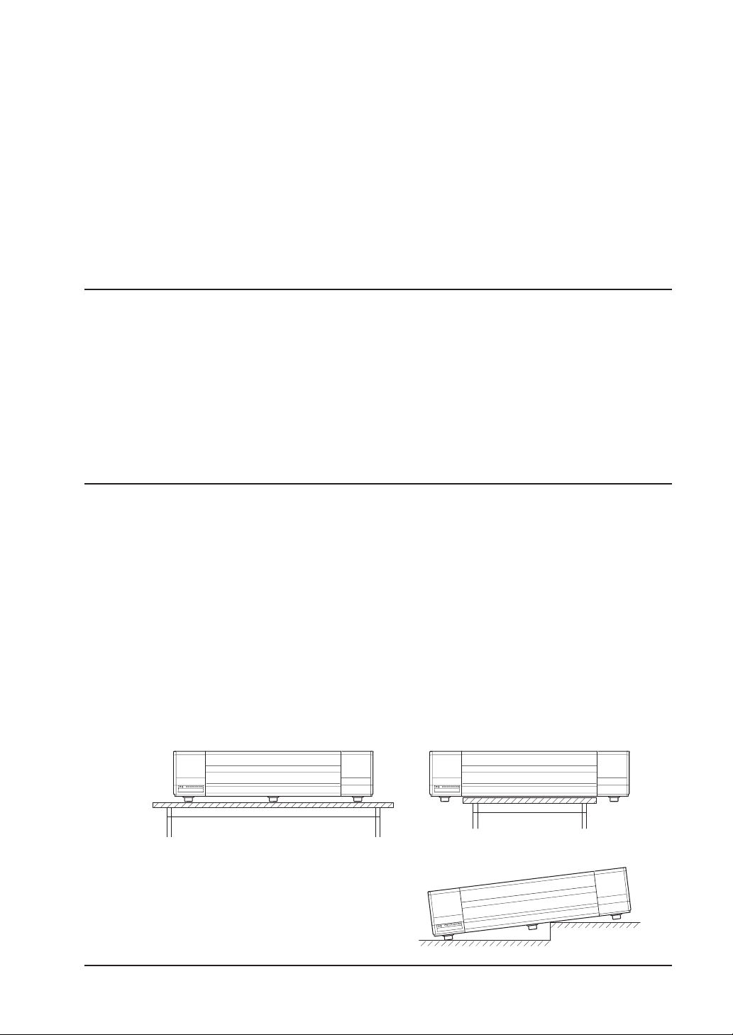
Precautions to observe when installing the printer
If the printer will be installed as a desktop model, be sure to heed the following points.
• Install the printer on a flat desk.
• Make sure that all five rubber feet are sitting on the desk.
• Do not install the printer on a stepped surface.
(Installing the printer in a location where its underside is touching another object may
cause malfunctions to occur.)
If there is no desk available for installation, mount the printer on the dedicated stand
(ST0060) that is available as an option.
Correct Incorrect
Incorrect
xi
Page 13

Precautions to observe when handling the paper
• Paper may not be fed correctly and may become jammed if the leading edge of the
roll paper is not straight or if there is adhesive from the fastening tape remaining on
the paper. Make sure that the leading edge is straight before loading the paper in the
printer.
• Paper feed problems or paper jams may occur if paper that is not Graphtec-supplied
paper is used. Be sure to use Graphtec-supplied paper.
• Depending on the storage conditions, the paper may become creased and/or the
leading edge may curl up. The use of creased or curled paper may cause paper jams.
Remove the creased or curled sections before loading the roll paper in the printer.
(If you are using a cut sheet, remove the creased section before loading the sheet in
the printer.)
Notes on the ink cartridges
Do not leave an ink cartridge that has been removed from the printer lying around for an
extended period of time. Doing so may cause ink deterioration, inferior print quality, or
clogging of the print head nozzles.
Notes on the print heads
Do not perform any unnecessary print head removal or mounting operations. Print head
removal and mounting operations should only be performed when print head replacement is required.
Be sure to observe the following points when loading paper in
the A2-size paper feed cassette
• Align the edges of the paper stack before loading it in the tray.
• Do not use paper that has been folded or creased.
• Fan the paper stack thoroughly before loading it in the tray.
If the paper is not fanned, paper jams may occur or two or more sheets may be fed at
the same time.
xii
Page 14

Notes on connecting the printer to a power outlet
Always leave the printer connected to a power outlet.
The printer periodically performs automatic maintenance operations in order to maintain
print quality.
xiii
Page 15

WARNING
Only computers or peripherals (computer input/output devices, terminals, printers, etc.)
certified as complying with the limits for a Class B digital device, pursuant to Part 15 of
the FCC Rules, may be attached to this product when this product is operated in a
residential environment. Operation with non-certified peripherals is likely to result in
interference to radio and TV.
FEDERAL COMMUNICATIONS COMMISSION RADIO FRE-
QUENCY INTERFERENCE STATEMENT
"This equipment has been tested and found to comply with the limits for a Class B
digital device pursuant to Part 15 of the FCC Rules. These limits are designed to
provide reasonable protection against harmful interference in a residential installation.
This equipment generates, uses, and can radiate radio frequency energy and, if not
installed and used in accordance with the instructions, may cause harmful interference
to radio communications. However, there is no guarantee that interference will not occur
in a particular installation. If this equipment does cause harmful interference to radio or
television reception, which can be determined by turning the equipment off and on, the
user is encouraged to try to correct interference by one or more of the following measures:
• Reorient or relocate the receiving antenna.
• Increase the separation between the equipment and receiver.
• Connect the equipment into an outlet on a circuit different from that to which the
receiver is connected.
• Consult the dealer or an experienced radio/TV technician for help."
xiv
Page 16

PREFACE
Thank you for choosing the Graphtec JW220-06 inkjet printer.
Please read this manual thoroughly before attempting to use your new product to
ensure that you use it safely and correctly.
Notes on this Manual
(1) No part of this publication may be reproduced, stored in a retrieval system, or
transmitted, in any form or by any means, without the prior written permission of
Graphtec Corporation.
(2) The product specifications and other information in this manual are subject to
change without notice.
(3) While every effort has been made to provide complete and accurate information,
please contact your sales representative or nearest Graphtec vendor if you find any
unclear or erroneous information or wish to make other comments or suggestions.
(4) Notwithstanding the stipulations in the preceding paragraph, Graphtec Corporation
assumes no liability for damages resulting from either the use of the information contained herein or the use of the product.
Registered Trademarks
All names of companies, brands, logotypes, and products appearing in this manual are
the trademarks or registered trademarks of their respective companies.
Copyright
This User's Manual is copyrighted by Graphtec Corporation.
Precautions to Observe When Transporting the Printer
Be sure to read Section 5.8, "Precautions on Transporting the Printer" before transporting the printer to another destination. Do not transport the printer as is, as there is a
possibility of the ink leaking out. If you have any questions or if anything is unclear,
please contact your sales representative or nearest Graphtec vendor.
I
Page 17

Contents
TO ENSURE SAFE AND CORRECT USE ..................................................................................... i
PREFACE ....................................................................................................................................... I
Notes on this Manual......................................................................................................... I
Registered Trademarks ..................................................................................................... I
Copyright ........................................................................................................................... I
Precautions to Observe When Transporting the Printer.................................................... I
Chapter 1 Before Using the Printer ............................................................................................. 1-1
1.1 Checking the Contents of the Package ................................................................... 1-1
1.2 Parts Names and Functions .................................................................................... 1-2
Front View ............................................................................................................... 1-2
Control panel ........................................................................................................... 1-2
Rear View................................................................................................................ 1-3
A2-size Paper Feed Cassette ................................................................................. 1-3
Chapter 2 Connection and Preparations ..................................................................................... 2-1
2.1 Attaching the Paper Guide Table ............................................................................. 2-1
2.2 Attaching the A2-size Paper Feed Cassette ............................................................ 2-1
2.3 Connecting to the Power Supply ............................................................................. 2-2
2.4 Turning the Power On and Off ................................................................................. 2-2
Turning the Power On ............................................................................................. 2-2
Turning the Power Off ............................................................................................. 2-2
2.5 Mounting the Print Heads ........................................................................................ 2-3
2.6 Mounting the Ink Cartridges .................................................................................... 2-6
2.7 Mounting the Roll Paper Cutter ............................................................................... 2-8
2.8 Connecting the Printer to a Computer ................................................................... 2-10
USB Connection.................................................................................................... 2-10
Ethernet connection (option) ................................................................................. 2-11
Chapter 3 Loading the Paper ...................................................................................................... 3-1
3.1 Usable Paper Types ................................................................................................ 3-1
Paper Types and Sizes ........................................................................................... 3-1
Print Area ................................................................................................................ 3-3
3.2 Using Roll Paper ..................................................................................................... 3-6
Loading roll paper ................................................................................................... 3-6
Removing roll paper ................................................................................................ 3-9
3.3 Using Cut Sheets .................................................................................................. 3-10
Loading cut sheets ................................................................................................ 3-10
Removing a cut sheet ........................................................................................... 3-12
II
Page 18

3.4 Using the A2-size Paper Feed Cassette ............................................................... 3-13
Attaching and removing the A2-size paper feed cassette ..................................... 3-13
Loading paper in the A2-size paper feed cassette ................................................ 3-15
Manual feeding...................................................................................................... 3-17
3.5 Using the Anti-Curling Guides ............................................................................... 3-19
Chapter 4 Printer Driver .............................................................................................................. 4-1
4.1 Printing from Windows ............................................................................................ 4-1
4.2 Canceling Printing in Windows ................................................................................ 4-3
4.3 Printer Driver Capabilities........................................................................................ 4-4
Main driver features ................................................................................................ 4-4
Compatible Operating Systems .............................................................................. 4-4
4.4 Printer Driver Functions........................................................................................... 4-5
[Base Setting] tab .................................................................................................... 4-5
[Options] tab ............................................................................................................ 4-8
[Graphics] tab ........................................................................................................ 4-10
[Color adjustment] tab ........................................................................................... 4-11
[About This Driver] tab........................................................................................... 4-12
4.5 Printer Information Button ..................................................................................... 4-13
[Data Information] tab............................................................................................ 4-13
[Printer Information] tab......................................................................................... 4-14
[Maintenance] tab.................................................................................................. 4-16
4.6 Message Displays ................................................................................................. 4-17
Chapter 5 Maintenance ............................................................................................................... 5-1
5.1 Checking the Printer Information ............................................................................. 5-1
[Printer Information] dialog screen .......................................................................... 5-1
Launching the [Printer Information] dialog screen................................................... 5-2
5.2 Replacing the Print Heads and Ink Cartridges ........................................................ 5-3
Checking the print heads and ink cartridges ........................................................... 5-3
Replacing the print heads ....................................................................................... 5-4
Replacing the ink cartridges .................................................................................... 5-8
5.3 Print Head Cleaning and Alignment ...................................................................... 5-10
Cleaning the Print Heads ...................................................................................... 5-10
Wiping the print heads .......................................................................................... 5-12
Aligning the print heads......................................................................................... 5-14
5.4 Handling the Print Heads ...................................................................................... 5-15
5.5 Replacing the Roll Paper Cutter ............................................................................ 5-16
5.6 Cleaning the Printer............................................................................................... 5-19
III
Page 19

5.7 Cleaning the Maintenance Station ........................................................................ 5-21
5.8 Transporting the Printer......................................................................................... 5-24
Attaching the various shock-absorbing packing materials .................................... 5-27
Packing the components into the packing box ...................................................... 5-27
Chapter 6 What to Do if This Happens ....................................................................................... 6-1
6.1 When an Error Message is Displayed ..................................................................... 6-1
Messages relating to paper ..................................................................................... 6-1
Messages relating to the print heads and ink cartridges ......................................... 6-2
Messages relating to the printer .............................................................................. 6-2
Messages relating to the print server connection and messages displayed during
connection monitoring ............................................................................................. 6-3
6.2 The Printer Does Not Operate Correctly ................................................................. 6-4
6.3 When Printing is not Satisfactory ............................................................................ 6-5
6.4 If the Paper Becomes Jammed ............................................................................... 6-6
Removing jammed roll paper .................................................................................. 6-6
Removing a jammed cut sheet................................................................................ 6-8
6.5 What to Do When Other Devices Cannot be Recognized..................................... 6-11
Appendix A Standard Specifications ........................................................................................... A-1
A.1 External Dimensions and Weight Standard Specifications ...................................A-1
A.2 External Dimensions and Weight When the A2-size paper feed cassette is installed
A-1
A.3 External Dimensions and Weight When the printer is mounted on a stand (ST0060:
option) .....................................................................................................................A-2
A.4 Standard Specifications ..........................................................................................A-3
Appendix B Options and Supplies............................................................................................... A-4
B.1 Options.................................................................................................................... A-4
B.2 Supplies ..................................................................................................................A-4
B.3 Cartridges for use when transporting the printer..................................................... A-5
Index .................................................................................................................................... Index-1
IV
Page 20

Chapter 1 Before Using the Printer
1.1 Checking the Contents of the Package
Check to confirm that all of the items shown below are present. If any item is missing,
promptly contact the store where you purchased your printer or your nearest Graphtec
representative.
Printer unit ···1
Power cable ···1
USB cable ···1
Print heads
(Black, color) ···1 of each
Paper guide table
(with two setscrews) ···1 set
A2-size Paper Feed Cassette ···1 set
Phillips screwdriver ···1
Ink cartridges
(Black, cyan, magenta, yellow) ···1 of each
Quick Start Guide ···1
Roll paper cutter ···1
Anti-curling guides ···2
Roll paper stocker ···1 assembly
Software package (CD-ROM) ···1
· Printer driver
· User's manual (PDF format)
· Adobe Acrobat Reader
1-1
Page 21
1.2 Parts Names and Functions
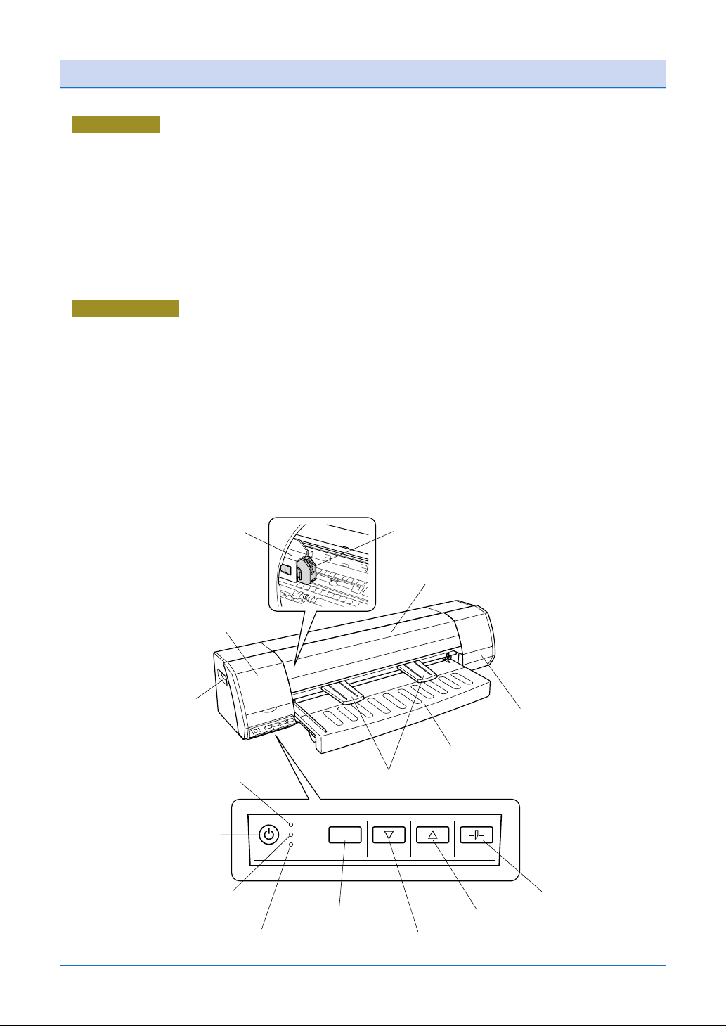
Front View
(1) Center cover ................. Used when mounting the roll paper cutter and when cleaning the inside of
the printer unit.
(2) Maintenance cover........ Used when the print heads are replaced. (Print head replacement position)
(3) Handholds ..................... These handles (located at the left and right sides of the printer) are used to
grip the printer when moving it.
(4) Anti-curling guides......... These guides are attached when thin media such as tracing paper is used.
(5) Paper guide table .......... Used for loading paper for printing.
(6) Ink cartridge cover ........ Used when mounting the ink cartridges. (Ink holder)
(7) Roll paper cutter ............ Used for cutting roll paper.
(8) Cutter holder ................. Used to mount the roll paper cutter.
Control panel
(9) [POWER] button ........... Press this button to turn the power supply to the printer on or off. The button
lights (blue) when the power supply is on.
(10) [DATA] LED ................. Flashes (green) when data is being received from the computer.
(11) [CAUTION] LED .......... Lights (orange) when the printer is out of paper.
(12) [ERROR] LED ............. Lights (red) when there is a paper jam, when the print head carrier stops, or
when some other malfunction occurs.
(13) [CANCEL] button ........ Press this button to cancel the printing operation.
(14) [FORWARD] button..... Press this button to feed the paper in the forward direction when the printer
is in standby status.
(15) [REVERSE] button ...... Press this button to feed the paper in the reverse direction when the printer
is in standby status.
(16) [PAPER CUT] button... Press this button to cut roll paper when the printer is in standby status.
(8) Cutter holder
(2) Maintenance cover
(Print head replacement position)
(3) Handholds
(10) [DATA] LED
(flashes green)
(9) [POWER] button
(lights blue)
(11) [CAUTION] LED
(lights orange)
(12) [ERROR] LED
(lights red)
(4) Anti-curling guides
DATA
CAUTION
ERROR
CANCEL FORWARD REVERSE PAPER CUT
(13) [CANCEL] button
(14) [FORWARD] button
(7) Roll paper cutter
(1) Center cover
(6) Ink cartridge cover
(Ink holder)
(5) Paper guide table
(16) [PAPER CUT] button
(15) [REVERSE] button
1-2
Page 22

Rear View
(17) Roll paper stocker .................. Used for loading roll paper for printing.
(18) Access door ........................... Open this door to remove the paper if it becomes jammed.
(19) Power inlet ............................. Used to connect the power cable.
(20) USB interface connector ........ Used to connect the USB cable.
(17) Roll paper stocker
(18) Access door
(19) Power inlet
(20) USB interface connector
A2-size Paper Feed Cassette
The A2-size paper feed cassette is designed specifically for feeding plain paper.
Cut sheets of standard-size paper, from A4-size to A2-size*1, can be loaded in the A2-size
cassette to enable automatic feeding of paper to the printer.
*1: Please note that only paper of the same size can be loaded at one time in the cassette.
The number of cut sheets that can be loaded
*2
• Plain paper (64 g/m2): approx. 100 sheets
*2: The number of sheets is a guideline only. When actually loading the paper in the
cassette, make sure that the top of the stack is below the line under the [ ]
mark printed on the stock tray.
Paper alignment levers ............ Move these levers to match the paper size and hold the paper in
place.
Stock tray ................................. Used to load cut sheets for feeding.
Paper guide table..................... Use this table when manually feeding sheets for printing.
Paper stack
height
Stock tray
Paper alignment levers
Paper guide table
1-3
Page 23

Chapter 2 Connection and Preparations
2.1 Attaching the Paper Guide Table
Firmly insert the paper guide table into the printer until it makes contact with the rear
side, and then fasten it in place with the two setscrews provided.
Paper guide table
Setscrews
Phillips screwdriver
provided with the printer
2.2 Attaching the A2-size Paper Feed Cassette
Attach the A2-size paper feed cassette, insert it fully into the printer as shown in the
diagram below. After the cassette has been inserted, gently pull on it to check that it is
firmly inserted.
Stock tray
2-1
Page 24
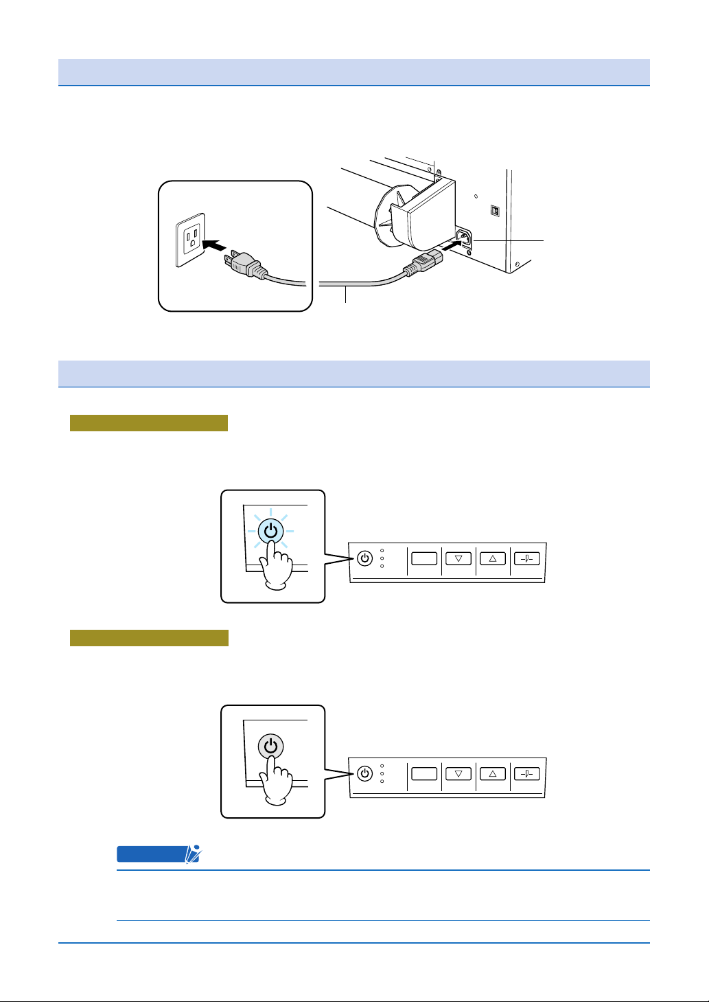
2.3 Connecting to the Power Supply
Connect one end of the power cable provided to the printer's power inlet and the other
end to an AC power outlet of the rated supply voltage.
AC power outlet
Power cable
2.4 Turning the Power On and Off
Turning the Power On
Press the [POWER] button on the printer's control panel.
When the printer is in the power-on status, the [POWER] button lights blue.
Power inlet
DATA
CAUTION
ERROR
CANCEL FORWARD REVERSE PAPER CUT
ON
Turning the Power Off
Press the [POWER] button on the printer's control panel.
When the printer is in the power-off status, the [POWER] button LED is extinguished.
DATA
CAUTION
ERROR
CANCEL FORWARD REVERSE PAPER CUT
OFF
CHECKPOINT
After the printer has been turned off, wait at least five seconds before turning it
on again.
2-2
Page 25

2.5 Mounting the Print Heads
1. Press the printer's [POWER] button to turn on the printer.
Check that the [POWER] button LED lights blue.
ON
2. Open the maintenance cover at the left-hand side of the printer.
Maintenance cover
3. The print head carrier moves to the print head replacement position.
DATA
CAUTION
ERROR
CANCEL FORWARD REVERSE PAPER CUT
Print head carrier
4. Press down on the lock to open the joint block.
2
Lock
1
2-3
Joint block
Page 26
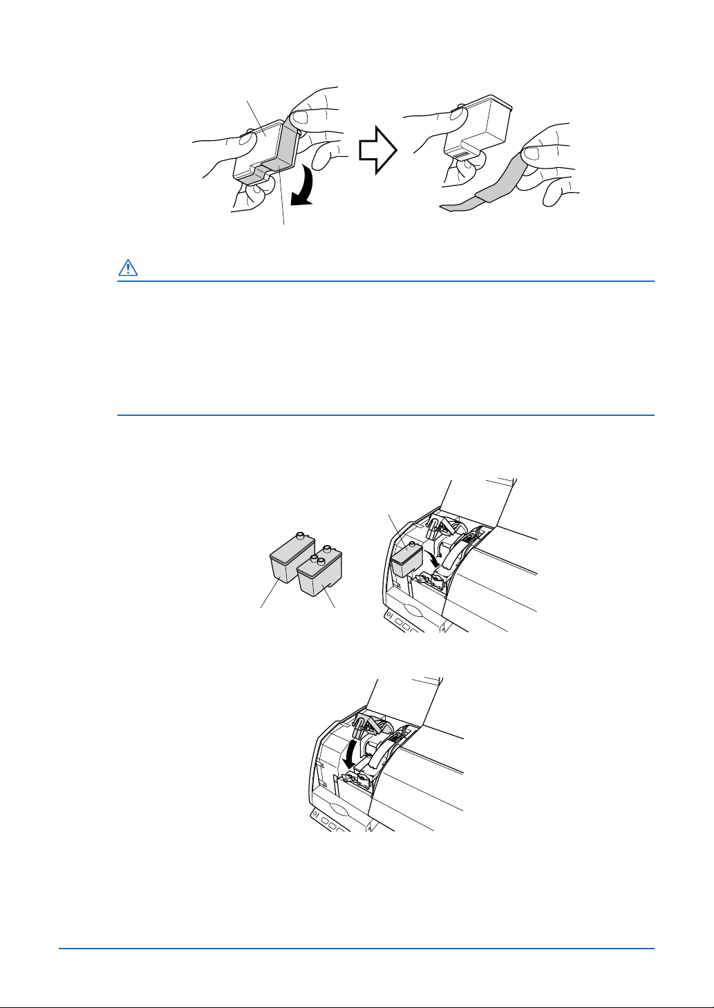
5. Prepare the print heads for mounting by removing the protective tape.
Print head
Protective tape
CAUTION
• Do not drop or shake the print head. Such actions may cause the ink to leak or
spatter, with the risk of staining your surroundings and clothing. Moreover, the
head section may become damaged, making the print head unusable.
• Do not touch the metallic parts of the print head or the print head section itself.
Such actions will adversely affect the printing. Moreover, there is a risk of
damage to the print head from static electricity.
6. Mount the print heads. Mount the black print head in the left-hand holder. Next,
mount the color print head in the right-hand holder.
Print head
(black)
Print head
(black)
Print head
(color)
7. Press down on the joint block until it makes an audible click.
2-4
Page 27

8. Gently close the maintenance cover.
2-5
Page 28

2.6 Mounting the Ink Cartridges
CHECKPOINT
• Before mounting the ink cartridges, make sure that the print heads have been
mounted.
• Perform this procedure with the printer in the power-on status. Check that the
[POWER] button is lit blue.
• There are four types of ink cartridges: black (BK), cyan (C), magenta (M) and
yellow (Y). Check their mounting positions in the ink holder in the printer, and
make sure that each cartridge is mounted correctly.
1. Open the ink cartridge cover at the right-hand side of the printer.
1
2
Ink cartridge cover
(Ink holder)
2. Align each ink cartridge with its corresponding rail on the ink holder, and then insert it
gently until it clicks into place. At this time, check the color of each ink cartridge and
make sure that it is inserted at the correct position.
Rail
Ink cartridge
Black
Cyan
Magenta
Yellow
CAUTION
• Do not touch the printed circuit board part of the ink cartridges with your fin-
gers. Such action may cause damage due to static electricity.
• Do not drop or shake the ink cartridges. Such actions may cause the ink to leak
or spatter, with the risk of staining your surroundings and clothing.
2-6
Page 29
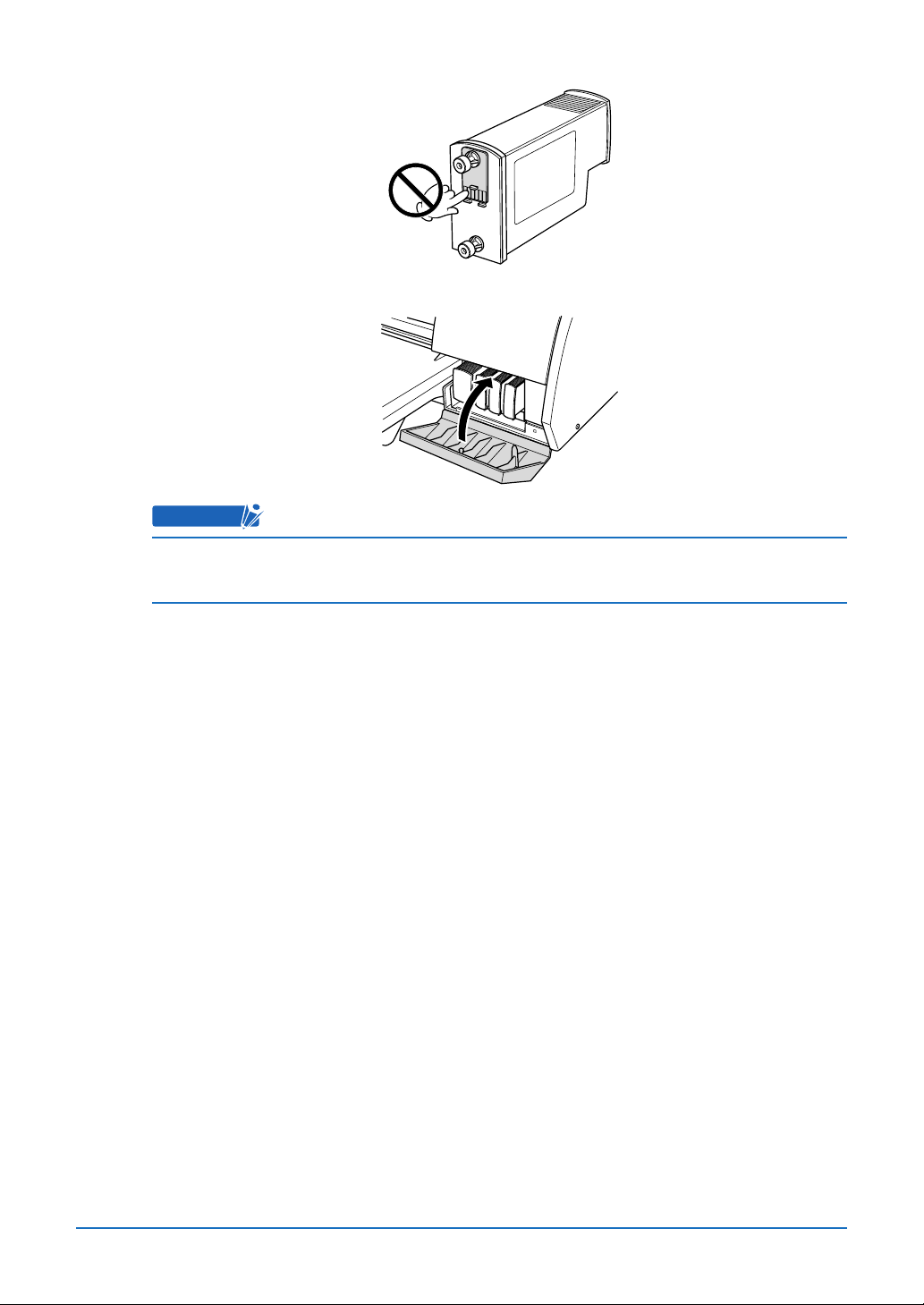
3. When all four ink cartridges have been mounted, gently close the ink cartridge cover.
CHECKPOINT
The printer driver can be used to check the status of the print heads and the ink
cartridges. For further details, see Chapter 4, "Printer Driver".
2-7
Page 30

2.7 Mounting the Roll Paper Cutter
CAUTION
• Take care not to cut your fingers or other parts of your body on
the roll paper cutter blade.
• When mounting the roll paper cutter, do not touch any of the
internal components of the printer other than the cutter holder.
Roll paper cutter
Take care with the blade inside the cutter
Note: The roll paper cutter is a consumable item.
1. Press the printer's [POWER] button to turn off the printer.
Check that the [POWER] button LED is extinguished.
OFF
2. Open the center cover.
Center cover
DATA
CAUTION
ERROR
CANCEL FORWARD REVERSE PAPER CUT
2-8
Page 31

3. Prepare the roll paper cutter for mounting.
Remove the protective tape (with a piece of sponge attached) from the tip of the roll
paper cutter blade, taking care not to cut yourself on the blade.
Protective tape
(with sponge attached)
Take care with the blade tip
Roll paper cutter
4. Hold the roll paper cutter by its lock tab, and insert the cutter firmly into the holder.
After the roll paper cutter has been mounted, check that the lock tab's hook is engaged in the cutter holder's slot.
Lock tab
Cutter holder
Lock tab hook
5. Close the center cover to complete the roll paper cutter mounting operation.
2-9
Page 32

2.8 Connecting the Printer to a Computer
USB Connection
A USB cable is used to connect the printer to the computer, via the respective USB
interface connectors. The connectors at the computer and printer ends of the USB
cable have different shapes. Make sure that the cable is oriented correctly before
making the connection.
Computer
USB cable
USB interface connector
IMPORTANT
Make sure that the USB cable is firmly inserted into the interface connectors.
When using a USB cable, a USB driver must be installed in the computer. Do not
connect the cable before the driver has been installed.
CHECKPOINT
Please see the separate "Quick Start Guide" for the printer driver installation
procedure.
2-10
Page 33

Ethernet connection (option)
If an Ethernet print server (option) is used, the printer can be used in a network environment. Please see the user's manual provided with the Ethernet print server (option) for
the network connection settings and other details.
1. Use the two screws provided with the Ethernet adapter to attach the adapter to the
printer.
Ethernet adapter
2. Mount the Ethernet print server on the Ethernet adapter.
Print server
3. Use the USB cable to connect the printer and the print server.
Next, use the Ethernet cable to connect the print server to the network.
Print server
Ethernet cable
Connect to network
USB interface connector
USB cable
2-11
Page 34

4. Connect the AC adapter to the print server.
Print server
1
AC adapter
3
Power cable
2
2-12
Page 35

Chapter 3 Loading the Paper
3.1 Usable Paper Types
The JW220 printer can handle a wide range of paper types up to A1 size (both roll
paper and cut sheets). Select the paper type that best suits your printing application.
In addition, use of the A2-size paper feed cassette enables automatic feeding of cut
sheets (plain paper) of the same size.
Paper Types and Sizes
The paper types and sizes that can be used with the JW220 printer are shown in the
following tables.
Paper types
Roll paper
Classification Name Part Name
Plain paper
Plain paper
Coated paper
Tracing paper
Glossy paper Photo paper
Recycled paper
Recycled paper
Matte
Ecological
Thick matte
Tracing paper
JC-∗∗R-PM
JC-∗∗R-PM-R2
JC-∗∗R-RMW2-R2
JC-∗∗R-RM2
JC-∗∗R-ST2
JC-∗∗R-ST2-R2
JC-∗∗R-RCT-R2
JC-∗∗R-STM2
JC-∗∗R-TM2
JC-∗∗R-WRP2
Abbre-
*1
viation
RMW2 64
Weight
(g/m2)
PM 64
RM2 64
ST2 90
RCT 80
STM2 117
TM 75
WRP 175
Thickness
(µm)
Approx.90
Approx.92
Approx.84
Approx.114
Approx.110
Approx.153
Approx.68
Approx.180
Features
80% whiteness
80% whiteness, 70% recycled-paper content
Suitable for outputting check prints
70% whiteness, 100% recycled-paper content
Suitable for outputting check prints
Plain paper is used as the base
Suitable for outputting check prints and simple graphics
80% whiteness, 70% recycled -paper content
Suitable for outputting check prints
Plain paper is used as the base; white paper suitable for graphics
Suitable for outputting color drawings, posters, etc.
Thin type, high translucency, natural tracing paper
Fast-drying photo paper that is suitable for printing graphics
Vivid color reproduction; optimal for printing posters, etc.
Cut sheets
Abbre-
Weight
Classification Name Part Name
Plain paper
Tracing paper
Plain paper PM 64
Tracing paper
JC-∗∗L-PM-100
JC-∗∗L-TM2
*1
viation
TM 75
(g/m2)
Thickness
(µm)
Approx.90
80% whiteness
Approx.68
Thin type, high translucency, natural tracing paper
Features
*1 These part names are for Graphtec-supplied paper. The "∗∗" part of the name varies
according to the paper size selected. Please see Appendix B, "Options and Supplies" for further details.
IMPORTANT
• To obtain high quality printed results, be sure to use Graphtec-supplied paper.
• Some of the paper types may require a longer ink drying time than others.
Allow sufficient time for the ink to dry before handling the prints.
• When using plain (or recycled) paper when "Normal" is specified for the print
3-1
Page 36

quality setting and high-density (dark) printing is performed, the paper may
become wavy. If this happens, either change the print quality setting to "High
quality" or else use coated or glossy paper instead.
Paper sizes
Roll paper: The following roll paper sizes can be used.
The maximum roll diameter must be less than 100 mm, the inner core
diameter 2 inches, and the rolls outside wound (the print side is on the
outside of the roll).
Roll paper sizes (paper widths)
ISO A1 Paper width 594.0 mm
ISO A2 Paper width 420.0 mm
ISO A3 Paper width 297.0 mm
JIS B2 Paper width 515.0 mm
JIS B3 Paper width 364.0 mm
ARCH 24 Paper width 24 inch
CHECKPOINT
Please see Section 3.2, "Using Roll Paper" for details on how to load roll paper in
the printer.
Cut sheets: The following cut sheet sizes can be used.
Cut sheet sizes (paper sizes)
ISO A1 594.0 x 841.0 mm
ISO A2 420.0 x 594.0 mm
ISO A3 297.0 x 420.0 mm
ISO A4
JIS B2
JIS B3
JIS B4
210.0 x 297.0 mm
515.0 x 728.0 mm
364.0 x 515.0 mm
257.0 x 364.0 mm
CHECKPOINT
Please see Section 3.3, "Using Cut Sheets" for details on how to load cut sheets
in the printer.
3-2
Page 37

Print Area
The JW220 printer can print within the areas described below.
CAUTION
• Depending on how the paper is loaded in the printer, the margin sizes may vary
slightly.
• When the roll paper cutter is used to cut roll paper, the operating environment
may cause slight changes in the paper size (the length in the paper feed direc-
tion) to occur.
Roll paper
Printing can be performed in the area up to 5 mm from all the edges of the paper
(leading edge, trailing edge, left and right edges).
5mm
Leading edge
5mm
Paper size
Left edge
Paper feed direction
Print area Right edge
5mm
Trailing edge
5mm
3-3
Page 38

Cut sheets
Standard print area
Printing can be performed in the area up to 5 mm from the leading edge, 13 mm from
the trailing edge, and 5 mm from the left and right edges. (When "Wide" has been
selected for "Margin Settings" in the driver setting menu.)
5mm
Leading edge
5mm
Paper size
Left edge
Paper feed direction
Print area Right edge
13mm
Trailing edge
5mm
Expanded print area
Printing can be performed in the area up to 5 mm from all the edges of the paper
(leading edge, trailing edge, left and right edges). (When "Narrow" has been selected
for "Margin Settings" in the driver setting menu)
5mm
Leading edge
5mm
Paper size
Left edge
Paper feed direction
Print area Right edge
5mm
Trailing edge
5mm
3-4
Page 39

CAUTION
• With the Expanded print area, the print quality may deteriorate at the trailing
edge.
• The guaranteed area for accurate printing is the area where the margins are 5
mm for the leading edge, 13 mm for the trailing edge, and 5 mm for the left and
right edges.
3-5
Page 40

3.2 Using Roll Paper
IMPORTANT
• To obtain high quality printed results, be sure to use Graphtec-supplied paper.
• The rolls must be outside wound, with printing performed on the outer surface.
When loading a roll of paper in the printer, try to avoid touching the printing
surface directly with your hands.
Fingerprints on the printing surface will adversely affect ink adhesion.
• Take care not to cut your fingers on the edges of the paper when handling it.
• Paper may not be fed correctly and may become jammed if the leading edge of
the roll paper is not straight or if there is adhesive from the fastening tape
remaining on the paper. Make sure that the leading edge is straight before
loading the paper in the printer.
Loading roll paper
1. Press the printer's [POWER] button to turn on the printer.
Check that the [POWER] button LED lights blue.
Note: Immediately after the power is turned on, the printer performs an initialization
operation. Wait until the initialization operation has been completed before
proceeding with the paper loading operation.
2. Check the direction in which the paper is wound, and then slide the roll onto the
stocker shaft. At this time, slide the roll along the shaft until its right edge (as shown
in the figure) fits onto the flange. Next, firmly insert the stopper so that it fits into the
core at the other end of the roll.
Roll paper
Stocker shaft
Stopper
FlangeStopper
Roll paper
CAUTION
If the paper edges are not flush with the core at the sides of the roll, printing will
3-6
Page 41

not be performed correctly. Make sure that that the paper edges at both the left
and right sides of the roll are flush with the core.
The roll paper edges are
flush with the core
Roll paper
Roll paper edges
3. Check that the access door is closed.
If it is open, close it.
Access door
The roll paper edges are
not flush with the core
Roll paper Roll paper core
Uneven roll paper take-up
4. Insert the roll paper stocker holding the roll into the stocker holders, making sure that
the flange is at the right.
Flange
Stocker holders
5. Pull a length of paper out from the roll, making sure that the left and right sides are
pulled out evenly. Next, while making sure that there is no slack in the roll, place
your hands on the areas indicated by a black circle (●) in the figure below and guide
the leading edge of the paper into the paper feed slot until it contacts the feed rollers
inside the printer.
A "beep" sound is emitted, and the roll paper is loaded automatically.
3-7
Page 42

Paper feed slot
CAUTION
• Make sure that the left and right sides of the roll paper are pulled out evenly. If
the roll paper is loaded at an angle, the skew detection function will cause the
[ERROR] LED (red) on the control panel to light.
If the [ERROR] LED lights (red), follow the procedure described below to pull
the roll paper out toward the rear of the printer and then reload it.
Procedure
(1) Hold the roll paper that has been inserted into the paper feed slot at the left
and right edges, and pull it gently back toward the rear of the plotter (the side
with the roll paper stocker).
(2) Rotate the roll paper stocker toward the rear, and, while making sure that the
right edge touches the flange, wind the paper back onto the roll. At this time,
make sure that the left and right edges of the roll paper are flush with the
core.
(3) Press the [CANCEL] button on the control panel, and check that the [ERROR]
LED (red) is extinguished.
(4) Pull a length of paper out from the roll, making sure that the left and right
sides are pulled out evenly, and then insert the leading edge into the paper
feed slot once again.
• If the leading edge is cut on an angle, remove the roll paper stocker from the
printer, remove the roll from the stocker, and then trim the leading edge so that
it is parallel with the stocker.
6. The roll paper stops automatically at the printing position, and the printer is now
ready to print.
CHECKPOINT
• Make sure that there is no slack in the paper. If there is any slack, rotate the roll
paper stocker toward the rear to take up the slack, making sure that the right
edge is in contact with the flange.
3-8
Page 43

Removing roll paper
1. Press the printer's [POWER] button to turn on the printer.
Check that the [POWER] button LED lights blue.
Note: Immediately after the power is turned on, the printer performs an initialization
operation. Wait until the initialization operation has been completed before
proceeding with the paper removal operation.
2. Press the [REVERSE] button on the control panel to feed the paper toward the rear
of the printer.
REVERSE
3. Rotate the roll paper stocker in the reverse direction to take up the paper. Next,
remove the roll paper stocker from the stocker holders.
3-9
Page 44

3.3 Using Cut Sheets
IMPORTANT
• To obtain high quality printed results, be sure to use Graphtec-supplied paper.
• Load cut sheets with the printing surface face-down. When loading a cut sheet
in the printer, try to avoid touching the printing surface directly with your
hands.
Fingerprints on the printing surface will adversely affect ink adhesion.
• Take care not to cut yourself on the edges of the paper when handling it.
• Load cut sheets individually.
Loading cut sheets
1. Press the printer's [POWER] button to turn on the printer.
Check that the [POWER] button LED lights blue.
2. Check the orientation of the cut sheet, making sure that the printing surface is facedown, and then align the left edge of the sheet with the paper guide on the paper
guide table. Next, while lightly holding down the sheet, insert its leading edge into the
paper feed slot until it contacts the feed rollers inside the printer. A "beep" sound is
emitted, and the cut sheet is loaded automatically.
3-10
Page 45

Paper feed slot
Paper guide
The loading and printing directions of
standard-size printing paper
A4 size
A3 size
A2 size
A1 size
Push forward
Paper guide table
Printing paper
Printing surface
Insertion direction
Feed rollers
Cut sheet loading direction
Cut sheet
Beep
Cut sheet
A "beep" sound is emitted when
the cut sheet is inserted in the printer.
3. The cut sheet stops automatically at the printing position, and the printer is now
ready to print.
3-11
When the sheet is inserted a little further,
it is automatically fed and loaded.
Page 46

Removing a cut sheet
1. Press the printer's [POWER] button to turn on the printer.
Check that the [POWER] button LED lights blue.
2. Press the [FORWARD] button on the control panel to feed the sheet in the forward
direction.
FORWARD
3-12
Page 47

3.4 Using the A2-size Paper Feed Cassette
The A2-size paper feed cassette is designed specifically for feeding plain paper.
Cut sheets of standard-size paper, from A4-size to A2-size*, can be loaded in the A2size cassette to enable automatic feeding of paper to the printer.
* Please note that only paper of the same size can be loaded at one time in the cas-
sette.
The number of cut sheets that can be loaded
Paper type
Plain paper
(64 g/m
2
Loadable number
of sheets
Approx.
)
100 sheets
The number of sheets is a guideline only.
When actually loading the paper in the cassette,
make sure that the top of the stack is below the
line under the [ MAX ] mark printed on the
stock tray.
Remarks
CAUTION
• Plain paper is the only type of paper that can be loaded in the A2-size paper
cassette. When using cut sheets of tracing or other thin paper, load each sheet
manually on the cassette's paper feed table.
• Be sure to observe the following points when loading paper in the A2-size paper
feed cassette:
* Align the edges of the paper stack before loading it in the tray.
* Do not use paper that has been folded or creased.
* Fan the paper stack thoroughly before loading it in the tray.
If the paper is not fanned, paper jams may occur or two or more sheets may
be fed at the same time.
Attaching and removing the A2-size paper feed cassette
Attaching the cassette
1. Unfasten the two setscrews used to attach the paper guide table to the printer, and
then remove the paper guide table.
Phillips screwdriver
provided with the printer
Setscrew
3-13
Page 48

2. Attach the A2-size paper feed cassette at the location from which the paper guide
table was removed. To attach the A2-size paper feed cassette, insert it fully into the
printer as shown in the diagram below. After the cassette has been inserted, gently
pull on it to check that it is firmly inserted.
Stock tray
Removing the cassette
Grasp the cassette at both sides, raise it slightly and then pull it out toward you.
CAUTION
• Check that the A2-size paper feed cassette has been mounted correctly. Incor-
rect mounting may result in a paper jam or incorrect feeding of the paper.
• When using the printer with the A2-size paper feed cassette attached, make sure
that the printer is installed in a stable location. Moreover, make sure that the
feet on the printer and on the cassette are all positioned on the desk surface.
• When moving the printer, be sure to remove the A2-size paper feed cassette
first. Moving the printer with the cassette still attached will place an undue load
on the cassette. Moreover, if the cassette falls out of the printer, there is a risk
of a malfunction or injury.
3-14
Page 49

Loading paper in the A2-size paper feed cassette
1. Lift up the paper guide table, and remove it from the cassette.
Feed guide
CAUTION
A feed guide is attached to the underside of the paper guide table.
Take care not to touch this feed guide.
Paper guide table
2. Check that the printing surface is face-down, and then insert the stack of printing
paper (standard-size plain paper) in the stock tray. Check that the orientation of the
paper is correct, and that the stack is not too high. Align the stack's left edge with the
stock tray's left edge, and its top edge with the tray's innermost edge. Next, move the
paper alignment levers to match the paper size, and to hold the stack in place to
prevent it from shifting.
Note: Be sure to load the paper so that the printing surface is face-down.
3-15
Page 50

Paper stack height
Align with the left and innermost edges
Printing surface
Printing paper
(Standard-size paper)
Paper alignment levers
The loading and printing directions of
standard-size printing paper
A4 size
A3 size
A2 size
Insertion direction
3. Attach the paper guide table.
IMPORTANT
Make sure that the paper guide table is attached correctly. (Check that the protru-
sion at the left underside of the tray is correctly fitted into the cutout at the left
side of the stock tray).
Incorrect attachment of the paper guide table may result in a paper jam or in
incorrect feeding of the paper.
Protrusion
Cutout
3-16
Page 51

Manual feeding
Paper can still be fed into the printer manually even if the A2-size paper feed cassette
has been installed. In this case, paper that is fed manually is given priority. Insert sheets
for manual feeding one at a time.
IMPORTANT
• To obtain high quality printed results, be sure to use Graphtec-supplied paper.
• Make sure that the printing surface of the paper for manual feeding is face-
down. When loading the paper, try to avoid touching the printing surface di-
rectly with your hands.
Fingerprints on the printing surface will adversely affect ink adhesion.
• Take care not to cut your fingers on the edges of the paper.
• When using the manual paper feed function to perform printing, set the number
of sheets for printing to "1" in the printer driver. If the number of sheets has
been set to a multiple number, the paper loaded in the cassette will be used for
printing the second and subsequent sheets.
1. Press the printer's [POWER] button to turn on the printer.
Check that the [POWER] button LED lights blue.
Note: Immediately after the power is turned on, the printer performs an initialization
operation. Wait until the initialization operation has been completed before
proceeding with the paper loading operation.
2. Check the orientation of the sheet and that the printing surface is face-down, and
then align the left edge of the sheet with the paper guide on the paper guide table.
Next, while lightly holding down the sheet, insert its leading edge into the paper feed
slot until it contacts the feed rollers inside the printer.
A "beep" sound is emitted, and the cut sheet is loaded automatically.
3-17
Page 52

Paper feed slot
Push forward
Printing paper
Printing surface
Paper guide
The loading and printing directions of
standard-size printing paper
A4 size
A3 size
Insertion direction
A2 size
A1 size
Feed rollers
Cut sheet
loading direction
Cut sheet
Beep
Cut sheet
A "beep" sound is emitted when
the cut sheet is inserted in the printer.
3. The cut sheet stops automatically at the printing position, and the printer is now
ready to print.
When the sheet is inserted a little further,
it is automatically fed and loaded.
3-18
Page 53

3.5 Using the Anti-Curling Guides
If the paper used for printing is thin and curls up, attach the anti-curling guides before
starting the printing operation. Insert the anti-curling guides into the holes provided on
the printer, and then slide them to the right to lock them in place.
IMPORTANT
Be sure to attach the anti-curling guides when using thin paper such as tracing
paper. If printing is performed without the guides attached, there is a risk of the
leading edge being caught up in the paper feed slot at the front of the printer.
Anti-curling guides
3-19
Page 54

Chapter 4 Printer Driver
A printer driver is required to send data from the computer to the printer.
Be sure to install the OPS670 printer driver in the computer used to send data to your
printer for printing.
The OPS670 printer driver is compatible with the following Windows operating systems:
Windows XP, Windows 2000,
Windows Millennium Edition (Me), Windows 98 Second Edition (SE)
Note: Please see the separate "Quick Start Guide" for the OPS670 driver installation
procedure.
4.1 Printing from Windows
To print from a Windows application, follow the procedure described below.
IMPORTANT
When executing a printing operation from the computer, insofar as possible close
all the other applications that are not being used. If other applications are left
open, there is a risk that computer processing will slow down, affecting the
transfer of data for printing and causing a deterioration in the printing quality.
1. Select "Print" from the [File] menu in your application software.
2. Check that the Graphtec JW220-06 printer driver is displayed in the [Select Printer]
screen.Next, specify the "Number of copies" for "Page Range".
Note: The parameters displayed in the [Print] dialog screen may vary depending on
the application software used.
4-1
Page 55

Make other settings as required. Open the Printer Settings screen from the driver's
Properties dialog screen (click the "Preferences" button to open the Printer Settings
screen), and use the [Base Setting], [Options] and [Graphics] tabs to make settings
such as the paper type and feed method, and the print quality. For further details, see
Section 4.4, "Printer Driver Functions".
3. Click the [Print] button to start printing.
4-2
Page 56

4.2 Canceling Printing in Windows
To cancel printing, follow the procedure described below.
1. Open the Graphtec JW220-06 printer driver icon from the [Printers] folder.
2. Select the print job that you want to cancel, and then select [Cancel] from the [Document] menu. Check that the print job is deleted.
Print job
3. If the printer continues to process the print job and the DATA LED (green) is flashing,
press the [CANCEL] button.
DATA
CAUTION
ERROR
CANCEL FORWARD REVERSE PAPER CUT
4. If the print job still cannot be cancelled by performing the operations described
above, press the [POWER] button to turn off the power supply to the printer. Wait for
at least five seconds, and then turn the power on again.
4-3
Page 57

4.3 Printer Driver Capabilities
The easy-to-use OPS670 printer driver enables high quality printing of a wide range of
data, from monochrome and color CAD drawings through to images such as photographs.
Moreover, the driver continuously monitors the printer status, displaying print head
information via the printer information dialog screen, as well as various messages, on
your computer's screen.
Main driver features
• Enables the drawing of black single-color line segments and various types of line
segment settings (line width. line pitch, etc.) that are necessary for the output of CAD
drawings.
• The printer status can be checked at the Printer Information dialog screen.
• [Data Information] tab:
Click this tab to display a list of the printer driver settings.
• [Printer Information] tab:
Click this tab to display print head and ink cartridge information. Click the [Refresh]
button to display the most recent printer information.
• [Maintenance] tab:
Click this tab to perform print head cleaning and alignment.
• Message display:
Displays the printer status when an error has occurred, or when a job is being
output.
Compatible Operating Systems
The OPS670 printer driver is compatible with the following Windows operating systems:
Windows XP, Windows 2000,
Windows Millennium Edition (Me), Windows 98 Second Edition (SE)
4-4
Page 58

4.4 Printer Driver Functions
Note: The Windows XP environment is used for the screens in the explanations.
[Base Setting] tab
Use this tab to make basic printer-related settings such as Print quality, Paper Source,
and Paper Size.
Paper Source
Paper Size
Print Area
Margin
Orientation
Use this parameter to specify the printer's paper source.
Select either "Roll Paper" or "Cut Sheet".
Make sure that the paper loaded in the printer (roll paper or cut sheet) is
the same as the setting specified in the driver.
Use this parameter to specify the size of the paper that will actually be
used for printing.
Either select a standard paper size or specify your desired paper size.
For long-length prints or other special applications where there is no
The actual printing or output area is displayed here.
The displayed size represents the print size after the print margins have
been subtracted.
Use this parameter to specify the print margins (the areas where printing
cannot be performed). If "Roll Paper" has been specified for "Paper
Source", this parameter is displayed in gray and the margins are a fixed
size.
• Roll Paper Leading: trailing, and left/right edges: All 5 mm
If "Cut Sheet" was selected for the paper source, select either "Narrow" or
"Wide".
• Cut Sheet (Narrow): Leading, trailing, and left/right edges: All 5 mm
• Cut Sheet (Wide): Leading edge: 5 mm, trailing edge: 13 mm,
left/right edges: 5 mm
Select the orientation to suit the direction in which the paper is loaded.
Use the drawing of the printer at the left of the screen to check the
orientation.
4-5
Page 59

90 Rotated
Mirror
Print quality
Paper type
Color/
Mono mode
Use these parameters to print the image rotated 90 degrees or as a mirror
image.
Use the direction of the "F" symbol in the drawing of the printer at the left of
the screen to check the rotation.
Use this parameter to specify the print quality.
Select from "High-speed", "Normal", and "High quality"
• High-speed: The printing speed takes priority.
This setting is suitable for check printing.
• Normal: Printing is performed at normal speed and quality.
• High quality: The printing quality takes priority.
The slower the print speed, the higher the printing quality.
Use this parameter to specify the paper type that you plan to use. For
optimal results, make sure that the paper type selected matches the paper
that is loaded in the printer.
Use this parameter to specify monochrome or color printing, and the type
of application.
Select from "Color drawing", "Color graphic", "Monochrome drawing", and
"Monochrome graphic".
• "Color drawing", "Monochrome drawing"
Use these settings when outputting CAD drawings, text data, and so
forth.
• "Color graphic", "Monochrome graphic".
Use these settings when outputting data with a lot of solid-fill areas, such
as photos or computer graphics data.
Speed
Precedence
Copies
Printer
Information
Restore
Defaults
Use this parameter to specify the printing speed.
Speed Precedence
The print quality takes precedence. However, the printing speed is slow.
To give even more priority to the print quality, select [Base Setting] tab
>"Print quality" > "High quality".
Speed precedence
The printing speed takes precedence. However, depending on the
content, the printing quality may be a little coarse.
To give even more priority to the printing speed, select [Base Setting]
tab >"Print quality" > "High-speed".
The "Speed Precedence" parameter can only be specified for the
following setting conditions.
• "Print quality" > "Normal"
• "Paper type" > "Plain"
• "Color/Mono mode" >"Monochrome drawing"
Use this parameter to specify the number of copies to be printed.
Click the [Printer Information] button to open the [Printer Information] dialog
screen.
The Printer Information] dialog screen is used to display information
relating to the print heads and ink, as well as to perform printer
maintenance.
For further details, see Section 4.5, "Printer Information Button".
Click the [Restore Defaults] button to return all the [Base Setting] tab
settings to their default values.
4-6
Page 60

IMPORTANT
Notes on the printer driver settings and the printing quality.
If "Speed Precedence" has been selected as shown in <Printer driver setting
"Speed Precedence"> below, depending on the type of data and the paper used,
the printing may be a little uneven in places.
<Printer driver setting "Speed Precedence">
• [Base Setting] tab > "Print quality" > "High-speed"
• [Base Setting] tab > "Speed precedence" > "Checkbox checked"
In these cases, since speed takes precedence during printing, the printing quality
may be a little coarse, making it suitable for check prints only.
To even out the printing, make the "Speed Precedence" settings shown below
and then perform printing.
<Printer driver setting "Speed Precedence">
• [Base Setting] tab > "Print quality" > "High quality" or "Normal"
• [Base Setting] tab > "Speed precedence" > "Checkbox unchecked"
If satisfactory image quality cannot be obtained even after making the above
settings, perform print head*1 and maintenance station*2 cleaning.
If the printer is used as is, there is a risk of shortening the life of the print heads.
Do not continue to use the printer in this status.
*1 Print head cleaning
(See Section 5.3, "Print Head Cleaning and Alignment" in this manual.)
*2 Maintenance station cleaning
(See Section 5.7, "Cleaning the Maintenance Station" in this manual.)
4-7
Page 61

[Options] tab
Use this tab to make settings such as Scaling and Offset, and to select whether or not
to cut the paper after printing.
Use this parameter to specify the scaling ratio.
Printing is normally performed at the 100% setting.
Scaling
The Scaling setting can be made in the 25 to 400% range, in 1% units.
Examples
To enlarge an A2-size image to A1-size, specify 141%.
To reduce an A1-size image to A2 size, specify 70%.
Offset
Paper cut
Drying Time
Distance
adjustment
Use this parameter to move the printing origin.
If a check is inserted in the "Offset" checkbox, the new origin position can
be specified by entering values in the X and Y directions, in 0.1-mm
increments.
Use this parameter to select whether or not to perform cutting of the paper
after a printing operation. Select either "Perform cut" or "No cut".
This parameter can only be specified when the paper source is "Roll
Paper".
Use this parameter to specify the length of time between data output
operations.
Use this parameter to adjust the distance in the paper feed direction.
If the paper type, thickness or other factors cause a discrepancy in the
paper feed distance to occur, enter a corrective value.
The corrective value can be set in the range from -3.00% to +3.00%, in
increments of 0.01%.
Example
If a 1 m (1000 mm) line segment is printed as 995 mm, set a corrective
value of 0.5%.
(1000 - 995) __ 1000 x 100 (%) = 0.5%
4-8
Page 62

Unit
Use this parameter to specify the display unit.
Select either "mm" or "inch".
Driver
(Printer folder)
settings take
priority
Register
Pen
Assignment
Line Pitch
Restore to
Defaults
If this checkbox is checked, printing is performed using the driver settings
that were set in the Printer folder and changes cannot be made from the
application software.
Click this button to save the driver settings to a file, and to load saved
settings.
Use this button when you want to change the color/line width of colors
displayed on the screen. Depending on the application software, it may not
be possible to make this setting.
The line pitch can be specified as a dotted line, dashed line, dot-dashed
line, or double-dot-dashed line.
Depending on the application software, it may not be possible to make this
setting.
Click this button to restore the [Option] tab settings to their default values.
4-9
Page 63

[Graphics] tab
Use this tab to make settings related to the processing of data for printing.
Use this parameter to specify the printing resolution.
The printing quality improves proportionately as the numerical value is
raised.
The upper limit of the value that can be specified for the resolution
Resolution
depends on the "Print quality" setting that was selected in the [Base
Setting] tab.
If printing is not performed satisfactorily such as in the cases listed below,
lower the resolution value to enable printing.
• Large text and large data files cannot be printed.
• Only part of the data is printed.
Output Vector
Data Only
Output Vector
to Halftone
Restore
Defaults
This parameter enables fast printing of drawings (mainly CAD drawings
where the lines, text and so forth are drawn using vector data),
However, raster data such as photographs or images cannot be printed.
Moreover, with some drawings, data such as solid-fill data may be defined
by the application software as raster data. If this is the case, remove the
check from the checkbox.
This parameter enables vector data to be printed as grayscale data.
This setting can be used when "Monochrome drawing" or "Monochrome
graphic" has been selected for "Color/Mono mode" in the [Base Setting]
tab.
Click this button to restore all the [Graphics] tab settings to their default
values.
4-10
Page 64

[Color adjustment] tab
Use this tab to make color-related settings for a printing operation.
Luminance
Contrast
Brightness
Saturation
Restore
Defaults
Use this parameter to adjust the shading of light areas.
Use this parameter to adjust the difference between the light and dark
areas.
Use this parameter to adjust the overall shading.
Use this parameter to adjust the hue of intermediate color areas.
This setting can be specified when "Color Drawing" or "Color Graphic" has
been selected for "Color/Mono mode" in the [Base Setting] tab.
Click this button to return all the [Color adjustment] tab settings to their
default values.
4-11
Page 65

[About This Driver] tab
The printer version information is displayed in this screen.
The information buttons displayed under the printer version information provide various
other useful functions such as a link to the Graphtec web site, checking information
related to your printer, and downloading of the most recent driver.
Be sure to make effective use of these buttons.
Note: To access the Graphtec web site, your computer must be connected to the
Internet.
Information buttons
4-12
Page 66

4.5 Printer Information Button
Click the [Printer Information] button to open the [Printer Information] dialog screen.
This dialog screen is used to display various types of information for the print heads
and cartridges and also to perform print head maintenance*.
*This function is enabled when the printer is in the power-on status.
Windows XP / Windows 2000 Windows Me / Windows 98SE
[Printer Information] button [Printer Information] button
[Data Information] tab
Click this tab to display a list of the printer driver settings.
4-13
Page 67

[Printer Information] tab
Display of warning and
replacement marks
Click this tab to display images showing the print head replacement time and the
amount of ink remaining in the ink cartridges. When a print head's replacement time is
near or when there is only a little ink remaining in an ink cartridge, a "warning mark" is
displayed on the relevant image to indicate that it is time to replace that print head or
ink cartridge.
If a warning mark is displayed, prepare a new print head (or ink cartridge) for replace-
ment, and then replace the indicated print head (or ink cartridge) with the new one as
soon as possible.
Click the [Refresh] button to display the most recent printer information.
Warning mark
• The indicated print head's replacement time is near. Have a new print head
ready for replacement.
• The amount of ink remaining in the cartridge is low. Have a new cartridge
ready for replacement.
Replacement mark
• The indicated print head must be replaced.
• The indicated ink cartridge must be replaced.
The print heads and ink cartridges are consumable items. Check the information
displayed on the [Printer Information] tab and have new print heads and ink cartridges
ready at hand before the current ones are used up.
IMPORTANT
[Notes on the Print Head and Ink Cartridge]
The print head and the ink cartridge replacement time are displayed on the
[Printer Information] tab.
A "warning mark" is displayed when a replacement time is near, and a "replace-
ment mark"*1 is displayed when a replacement time has been reached.
For the print head, to maintain image quality, we recommend that you replace the
indicated print head with a new print head as soon as possible after a “warning
mark” is displayed.
4-14
Page 68

For the ink cartridge, to maintain image quality, we recommend that you use the
ink completely within half a year after an ink cartridge has been opened.
Print head replacement guidelines :
• Black print head: One with short period either within one year after you buys it
or when four black ink cartridges has been used.
• Color print head: One with short period either within one year after you buys it
or when two color ink cartridges has bee used for the most
frequently used color.
*1 Correct print head and ink cartridge performance are not guaranteed up to the time
that the “replacement mark” is displayed.
CAUTION
• Be sure to replace the print head promptly when the replacement mark is dis-
played. Continuing to use the printer without replacing the indicated print head
may cause a malfunction.
• Printing is halted to protect the print head when a replacement mark is dis-
played for an ink cartridge. Replace the indicated cartridge. Printing can be
restarted after the cartridge has been replaced.
CHECKPOINT
See Chapter 5, "Maintenance" for details on how to replace the print heads and
ink cartridges.
4-15
Page 69

[Maintenance] tab
If the printing is scratchy or uneven, or if you are not satisfied with the printing quality,
use the [Maintenance] tab to perform printer maintenance. In addition, the [Maintenance] tab can be used to check the printer's firmware version.
[Print Head Cleaning] button
Click this button to print a test pattern and perform print head cleaning.
[Print Head Alignment] button
Click this button to print a test pattern and to automatically adjust the
alignment of the print heads.
The printer model and printer version are
displayed here.
CHECKPOINT
See Chapter 5, "Maintenance" for details on how to perform printer maintenance.
4-16
Page 70

4.6 Message Displays
When the printer requires some action to be taken, a message is displayed in the
[Printer Information] dialog screen that appears on your computer screen. If a message
is displayed, check the contents of the message and then take appropriate action.
The messages that are displayed mainly concern the following items.
• Messages relating to paper
• Messages relating to the print heads/ink cartridges
• Messages relating to the printer's covers
Message display
concerning
a printer cover
CHECKPOINT
• See Chapter 6, "What to Do When This Happens" for details on the message
contents and the actions that are required.
• Click the [Refresh] button to display the most recent printer information.
4-17
Page 71

Chapter 5 Maintenance
5.1 Checking the Printer Information
[Printer Information] dialog screen
The [Printer Information] dialog screen is used to display various types of information
for the print heads and cartridges, and also to perform print head maintenance.*
* This function is enabled when the printer is in the power-on status.
CHECKPOINT
Click the [Refresh] button to display the most recent printer information.
[Printer Information] tab
Click this tab to display print head
and cartridge information.
[Maintenance] tab
Click this tab to perform
print head maintenance.
5-1
Page 72

Launching the [Printer Information] dialog screen
When using Windows XP/Windows 2000
Click the [Print Settings] button on the [General] tab.
Next, click the [Printer Information] button on the [Base Setting] tab.
When using Windows Me/Windows 98SE
Click the [Printer Information] button on the [Base Setting] tab.
5-2
Page 73

5.2 Replacing the Print Heads and Ink Cartridges
Checking the print heads and ink cartridges
The [Printer Information] tab can be used to check the print head replacement time and
how much ink is remaining in the ink cartridges.
A "warning mark" is displayed for a print head when its replacement time is near, and
for an ink cartridge when there is only a little ink remaining in the cartridge, to indicate
that the print head or ink cartridge needs to be replaced.
Display of warning and
replacement marks
Warning mark
If displayed for a print head
• The indicated print head's replacement time is near. Have a new print head
ready for replacement.
If displayed for an ink cartridge
• The amount of ink remaining in the cartridge is low. Have a new cartridge
ready for replacement.
Replacement mark
If displayed for a print head
• The indicated print head must be replaced. If it is not replaced, a malfunction
may occur.
If displayed for an ink cartridge
• Printing is halted to protect the print head. Replace the indicated cartridge.
Printing can be restarted after the cartridge has been replaced.
IMPORTANT
[Notes on the Print Head and Ink Cartridge]
The print head and the ink cartridge replacement time are displayed on the
[Printer Information] tab.
A "warning mark" is displayed when a replacement time is near, and a "replace-
ment mark"*1 is displayed when a replacement time has been reached.
For the print head, to maintain image quality, we recommend that you replace the
indicated print head with a new print head as soon as possible after a “warning
mark” is displayed.
5-3
Page 74

For the ink cartridge, to maintain image quality, we recommend that you use the
ink completely within half a year after an ink cartridge has been opened.
Print head replacement guidelines :
• Black print head: One with short period either within one year after you buys it
or when four black ink cartridges has been used.
• Color print head: One with short period either within one year after you buys it
or when two color ink cartridges has bee used for the most
frequently used color.
*1 Correct print head and ink cartridge performance are not guaranteed up to the time
that the “replacement mark” is displayed.
Replacing the print heads
Be sure to observe the following precautions when replacing a print head.
CAUTION
• As a safety precaution, store print heads in a location out of the reach of small
children.
• If ink is licked or ingested accidentally, consult a doctor immediately.
IMPORTANT
• Be sure to use only the Graphtec print heads designed for the JW220 printer
(part numbers IH-90001BK, and IH-90002CMY).
• Do not touch the metallic parts of the print head or the print head section itself.
Such actions will adversely affect the printing. Moreover, there is a risk of
damage to the print head from static electricity.
• Do not drop or shake the print heads or ink cartridges. Such actions may cause
the ink to leak or spatter, with the risk of staining your surroundings and cloth-
ing. Moreover, the head section may become damaged, making the print head
unusable.
• Make sure that the printer is in the power-on status when replacing a print head.
Replacing a print head when the printer has been turned off may cause the print
head to malfunction.
5-4
Page 75

Print head replacement procedure
Note: The replacement procedure for the black print head is used as an example.
1. Press the printer's [POWER] button to turn on the printer.
Check that the [POWER] button LED lights blue.
DATA
CAUTION
ERROR
CANCEL FORWARD REVERSE PAPER CUT
ON
2. Open the maintenance cover at the left-hand side of the printer.
Maintenance cover
3. The print head carrier moves to the print head replacement position.
Print head carrier
4. Press down on the lock to open the joint block.
2
Joint block
Lock
1
5-5
Page 76

5. Lift up the print head to remove it.
Print head
6. Prepare a new print head for replacement by removing the protective tape.
Print head
Protective tape
7. Mount the new print heads.
Mount the black print head in the left-hand holder.
Mount the color print head in the right-hand holder.
Print head
(black)
Print head
(black)
Print head
(color)
8. Press down on the joint block until it makes an audible click.
5-6
Page 77

9. Gently close the maintenance cover.
This completes the print head replacement procedure.
10. Perform the print head alignment procedure before starting a printing operation.
For further details, see Section 5.3, "Print Head Cleaning and Alignment".
CHECKPOINT
The printer driver can be used to check the print head information.
For further details, see Chapter 4, "Printer Driver".
5-7
Page 78

Replacing the ink cartridges
Be sure to observe the following precautions when replacing an ink cartridge.
CAUTION
• As a safety precaution, store ink cartridges in a location out of the reach of
small children.
• If ink is licked or ingested accidentally, consult a doctor immediately.
IMPORTANT
• Be sure to use only the Graphtec ink cartridges designed for the JW220 printer
(part numbers IJ-90001BK, IJ-90001C, IJ-90001M, and IJ-90001Y).
• Do not touch an ink cartridge's printed circuit board.
Such action will adversely affect the printing. More-
over, there is a risk of damage to the ink cartridge
from static electricity.
• Do not drop or shake the ink cartridges. Such actions may cause the ink to leak
or spatter, with the risk of staining your surroundings and clothing.
• Before mounting an ink cartridge, make sure that the print heads have already
been mounted.
• There are four types of ink cartridges: black (BK), cyan (C), magenta (M) and
yellow (Y). Check the replacement ink cartridge’s position in the ink holder
before mounting it, and be sure to mount it correctly.
• Make sure that the printer is in the power-on status when replacing an ink
cartridge. Replacing an ink cartridge when the printer has been turned off may
cause the cartridge to malfunction.
• Do not leave an ink cartridge that has been removed from the printer lying
around for an extended period of time. Doing so may cause ink deterioration,
inferior print quality, or clogging of the print head nozzles.
Ink cartridges replacement procedure
1. Press the printer's [POWER] button to turn on the printer.
Check that the [POWER] button LED lights blue.
ON
5-8
DATA
CAUTION
ERROR
CANCEL FORWARD REVERSE PAPER CUT
Page 79

2. Open the ink cartridge cover at the right-hand side of the printer.
1
Ink cartridge cover
(ink holder)
2
3. Grasp the ink cartridge that you want to replace and pull it out by sliding it along its
corresponding rail on the ink holder.
4. Align the new cartridge with its corresponding rail on the ink holder, and then insert it
gently until it clicks into place. At this time, check the color of each ink cartridge and
make sure that the new cartridge is inserted at the correct position.
Rail
Ink cartridges
Black
Cyan
Magenta
Yellow
5. Gently close the ink cartridge cover.
This completes the ink cartridge replacement operation.
CHECKPOINT
The printer driver can be used to check the status of the ink cartridges. For
further details, see Chapter 4, "Printer Driver".
5-9
Page 80

5.3 Print Head Cleaning and Alignment
The [Maintenance] tab can be used to perform print head maintenance. Perform print
head maintenance if the printing is scratchy, uneven or otherwise unsatisfactory.
[Print Head Cleaning] button
Click this button to print a test pattern, and to perform print head cleaning.
[Print Head Alignment] button
Click this button to print a test pattern and to automatically adjust the
alignment of the print heads.
Perform print head alignment whenever a print head is mounted (replaced).
IMPORTANT
• Use plain white paper for the print head alignment procedure.
• If using a cut sheet, use a new sheet of paper that is at least A4 size, and load it
in the vertical direction.
Cleaning the Print Heads
1. Check that paper has been loaded correctly in the printer.
* Note: If using a cut sheet, use a new sheet of paper that is at least A4 size, and
load it in the vertical direction.
2. Click the [Print Head Cleaning] button on the [Maintenance] tab.
5-10
Page 81

3. The printer prints out a test pattern, and then proceeds to perform print head cleaning.
Note: The test pattern is printed in the order Cyan, Magenta, Yellow and Black,
starting from the top.
Cyan
Magenta
Yellow
Black
4. When the print head cleaning operation has been completed, print out some data
such as a drawing or text to check that the printing quality has improved.
CHECKPOINT
If there is no improvement in the printed results, perform the "wiping the print
heads" procedure.
IMPORTANT
[Points to note about the printed test pattern]
In the test pattern printed out for the print head cleaning operation, there may be
some very fine white stripes in the solid-fill areas. These stripes do not indicate a
malfunction, and we ask for your understanding.
Check the solid-fill areas for the conditions described below. If the image quality
is adversely affected, clean the print heads*1 and the maintenance station*2.
Conditions to check for:
• Considerably uneven printing in the solid-fill areas
• A large number of white streaks in the solid-fill areas
If the print heads are used when either of these conditions has been detected, the
print head life will be considerably shortened. Do not continue using the print
heads without performing cleaning.
*1 Print head cleaning
(See "Wiping the print heads" in Section 5.3, "Print Head Cleaning and Alignment" in
this manual.)
*2 Cleaning the Maintenance Station
(See Section 5.7, "Cleaning the Maintenance Station" in this manual.)
5-11
Page 82

Wiping the print heads
If there is no improvement in the printed results after the print head cleaning operation
described in the previous section has been performed, wipe off the ink from the print
head nozzles.
1. Remove the print heads from the printer.
See Section 5.2, "Replacing the Print Heads and Ink Cartridges", and follow steps 1
to 5 in the "Replacing the print heads" subsection.
Print head
2. Moisten a clean cloth with warm water.
3. Place two sheets of paper on a table or other flat surface, and then lay the moistened
cloth on top the paper, making sure that it is flat.
4. Lightly press the surface of the print head nozzles against the cloth for approximately
three seconds.
Moistened cloth
Paper (2 sheets)
5. Move the print head gently on top of the cloth, in the direction indicated by the arrow
in the figure so that the ink on the surface of the nozzles is wiped off.
6. Move the print head to a clean area of the cloth, and repeat steps 4 and 5.
5-12
Page 83

7. Mount the print head in the printer.
See Section 5.2, "Replacing the Print heads and Ink Cartridges", and follow steps 7
to 11 in the "Replacing the print heads" subsection.
8. Perform print head cleaning. See "Print Head Cleaning" in the previous section.
CHECKPOINT
If printing is still scratchy or uneven even after print head cleaning has been
performed, replace the print head with a new one.
5-13
Page 84

Aligning the print heads
IMPORTANT
• Use plain white paper for the alignment procedure.
• If using a cut sheet, use a new sheet of paper that is at least A4 size, and load it
in the vertical direction.
1. Check that the paper for printing has been loaded correctly.
2. Click the [Print Head Alignment] button on the [Maintenance] tab.
3. The printer prints a test pattern, and then automatically aligns the print head positions.
CAUTION
Ink ejection adjustment is performed during the print head alignment operation.
For this reason, scratchy areas may appear in the printed test pattern, but these
do not indicate a malfunction.
4. When the print head cleaning operation has been completed, print out some data
such as a drawing or text to check that the printing quality has improved.
If there is no improvement in the printed results, perform the print head alignment
operation once again. If the printing quality does not improve even after the print head
alignment operation has been performed several times, replace the print head.
5-14
Page 85

5.4 Handling the Print Heads
To maintain optimal print head printing quality, be sure to observe the following precautions.
• Do not touch the metallic parts of the print head or the print head section itself.
• When the power supply to the printer has been turned off, make sure that the print
heads are at the maintenance station position (at the very left of the printer).
If the print heads are not at the maintenance station position, turn on the printer. The
print heads will then return automatically to the maintenance station. After they have
returned to the maintenance station, turn the printer off again.
Print head carrier
• If the printer has not been used for over one week, perform print head cleaning before
using the printer. (See Section 5.3, "Print Head Cleaning and Alignment" in this
manual.)
• Clean the maintenance station at regular intervals. (See Section 5.7, "Cleaning the
Maintenance Station" in this manual.)
• Be sure to use Graphtec-specified paper. (See Section 3.1, "Usable Paper Types" in
this manual.)
• Do not perform any unnecessary print head removal or mounting operations. Print
head removal and mounting operations should only be performed when print head
replacement is required.
5-15
Page 86

5.5 Replacing the Roll Paper Cutter
The roll paper cutter is used to automatically cut across the roll paper after printing has
been completed, and also to cut the roll paper at any desired time.
If the roll paper is not cut cleanly, replace the roll paper cutter.
CAUTION
• When replacing the roll paper cutter, take care not to cut your fingers or other
parts of your body on the roll paper cutter blade.
• When replacing the roll paper cutter, do
not touch any of the internal components
in the printer other than the cutter holder.
Roll paper cutter
Note: The roll paper cutter is a consumable item.
Take care not to cut yourself
on the blade inside the cutter.
IMPORTANT
• Be sure to use the Graphtec roll paper cutter (Part no. CT03U) that has been
specifically designed for use with the JW220 printer.
• When replacing the roll paper cutter, do not touch any of the internal compo-
nents in the printer other than the cutter holder.
• Do not wipe the surface of the roll paper cutter blade with a cloth or similar
item, or dip the blade in water or other fluids.
• Do not disassemble or modify the roll paper cutter.
• When replacing the roll paper cutter, make sure that the printer is in the power-
off status.
Replacing the roll paper cutter
1. Press the [POWER] button to turn off the printer.
Check that the [POWER] button LED is extinguished.
DATA
CAUTION
ERROR
CANCEL FORWARD REVERSE PAPER CUT
OFF
5-16
Page 87

2. Open the center cover.
Center cover
3. While pressing down on the roll paper cutter's lock tab, pull the roll paper cutter out of
the cutter holder.
Cutter holder
Lock tab
4. Prepare the replacement roll paper cutter for mounting.
Remove the protective tape (with a piece of sponge attached) from the tip of the roll
paper cutter blade, taking care not to cut yourself on the blade.
Protective tape
(with sponge attached)
Take care with the blade tip
Roll paper cutter
5-17
Page 88

5. Hold the roll paper cutter by its lock tab, and insert the cutter firmly into the holder.
After the roll paper cutter has been mounted, check that the lock tab's hook is engaged in the cutter holder's opening.
Lock tab
Cutter holder
Lock tab hook
6. Close the center cover to complete the roll paper cutter replacement operation.
5-18
Page 89

5.6 Cleaning the Printer
Clean the printer whenever cleaning is required.
CAUTION
• Before cleaning the printer, turn off the printer's power supply and remove the
power cable from the power outlet. Cleaning the printer with the power left on
by mistake may result in injuries from contact with internal moving parts.
• Do not disassemble or remodel the printer. Such actions may result in a fire
hazard or electric shock.
• Do not use volatile solvents such as thinner, benzene, or alcohol to clean the
printer. Such action may result in a fire hazard or electric shock if a solvent
comes into contact with the printer's internal electrical components.
• Do not unplug or plug in the power cable when your hands are wet.
Such action may result in electric shock.
• Do not move the printer with its center cover in the raised position. The cover
may close suddenly due to vibrations or bodily contact, and may result in
injuries.
Cleaning the printer
Exterior surfaces
Using a cloth moistened with water and then firmly wrung out, wipe off any dirt on the
printer's exterior. Wipe over the cleaned surfaces once again with a dry cloth.
Interior surfaces
Rear surface of the center cover: Do not clean this surface, as doing so may attract
static electricity and cause the surface to become easily soiled.
Platen: Use a commercially-available cotton swab or similar item to clean out any paper
dust that has become embedded in the cutter groove or other areas. Cotton
swabs can also be used to remove ink stains. When performing cleaning, take
care not to damage the serrated rollers in front of the platen.
5-19
Page 90

Cotton swab
Cutter groove
Platen
Rollers (serrated)
Paper guide table
Using a cloth moistened with water and then firmly wrung out, wipe off any dirt on the
exterior of the paper guide table. Wipe over the cleaned surfaces once again with a dry
cloth.
A2-size paper feed cassette (option)
Using a cloth moistened with water and then firmly wrung out, wipe off any dirt on the
exterior of the paper feed cassette. Wipe over the cleaned surfaces once again with a
dry cloth.
CAUTION
Take care not to bend or pull on the feed guide located on the underside of the
paper guide table.
Paper guide table
Feed guide
Stand (option)
Using a cloth moistened with water and then firmly wrung out, wipe off any dirt on the
exterior of the stand. Wipe over the cleaned surfaces once again with a dry cloth.
5-20
Page 91

5.7 Cleaning the Maintenance Station
To maintain optimal print head printing quality, clean the maintenance station at regular
intervals.
1. Press the [POWER] button to turn off the printer.
Check that the [POWER] button LED is extinguished.
DATA
CAUTION
ERROR
OFF
2. Open the maintenance cover at the left-hand side of the printer.
Maintenance cover
CANCEL FORWARD REVERSE PAPER CUT
3. Manually move the print head carrier to the right.
Note: When moving the print head carrier, be sure to hold the section of the carrier
indicated in the figure below.
Move the carrier carefully,
taking care not to scratch
the cover.
5-21
Page 92

4. Using a clean cloth that has been lightly moistened with warm water (or cold water)
and then firmly wrung out, or a sheet of cotton paper, wipe off any dirt on the surface
of the wiper blades and the caps. Wipe the cleaned surfaces once again with a dry
cloth or another sheet of cotton paper.
Cap surfaces Wiper blades
CAUTION
• Do not use excessive force when wiping the components. Such action may
cause the wiper blades or caps to become deformed.
• Check that there are no fibers remaining after wiping the components. Fibers
left on the wiper blades or in the caps may become adhered to the print head
nozzles and cause a deterioration in print head performance.
• Take care not to get your hands or clothing soiled when performing a cleaning
operation.
• Perform cleaning operations within a 15-minute period. If cleaning is performed
for a longer period of time, the print head nozzles may dry up and adversely
affect the printing quality.
5. Gently close the maintenance cover.
5-22
Page 93

6. Press the printer's [POWERÅnbutton to turn on the printer.
Check that the [POWERÅnbutton LED lights blue. The print head carrier returns
automatically to the maintenance station, and the printer is ready to print.
DATA
CAUTION
ERROR
CANCEL FORWARD REVERSE PAPER CUT
ON
IMPORTANT
After cleaning the maintenance station, be sure to turn on the printer and check
that the print head carrier has returned properly to the maintenance station.
5-23
Page 94

5.8 Transporting the Printer
• When moving the printer within the same building:
(1) Remove the print heads and ink cartridges.
• When moving the printer (using a vehicle or other means of transportation) to a
different location:
(1) Remove the print heads and ink cartridges.
(2) Mount the transport-use cartridges.
(3) Promptly mount the print heads and ink cartridges after the printer has arrived at
its destination.
• Storing the printer (for longer than a month):
If the printer has not been connected to a commercial power supply
(1) Please consult your sales representative or nearest Graphtec vender, to extract
the ink from the tubes.
(2) Before using the printer again, mount the new print heads and ink cartridges (that
you purchased).
Before transporting the printer, be sure to perform the following preparatory procedure
to protect the printer's internal mechanisms.
Items that must be readied
• The JW220's original packing box and shock-absorbing packing materials
• One set of transport-use cartridges (MK-90001: Option) (One black, three color)
CAUTION
• If the printer is not readied for transport, there is a risk of ink spattering inside
the printer.
• Take care not to cut your hands or other parts of your body on the roll paper
cutter.
• Do not touch the printed circuit boards on the ink cartridges.
• Do not drop or shake the ink cartridges.
• When placing the printer in its packing box, be sure to observe the following
precautions:
The printer must be laid flat.
Do not stand the printer on end.
• When transporting the printer, be sure to label it ("This side up").
• Please consult your sales representative or nearest Graphtec vendor if the
printer will not be connected to a power outlet for at least a week or if you plan
to store the printer.
5-24
Page 95

Turning off the printer, and removing the cables
1. Press the printer's [POWER] button to turn off the printer.
Check that the [POWER] button LED is extinguished.
2. Remove the power cable and the USB cable.
Removing the Print Heads
3. Open the maintenance cover at the left-hand side of the printer.
4. Remove the print heads (black and color).
5. Lower the joint block and then press on it to lock it in place.
6. Close the maintenance cover.
7. Store the removed print heads in plastic bags or similar containers.
Removing the ink cartridges and mounting the transport-use cartridges
8. Open the ink cartridge cover at the right-hand side of the printer.
9. Remove all four ink cartridges by sliding them gently along their respective rails in
the ink holder.
10. Mount the transport cartridges.
There are two types: one for the black ink, and the other for the three colored inks.
Mount the cartridge for the black ink at the leftmost position in the ink holder by
sliding it along the rail until it clicks into place. There is no position specification for
the color cartridges. Mount one cartridge in each of the three empty positions in the
ink holder by sliding it along the rail until it clicks into place.
11. Place the ink cartridges that were removed in the box that contained the transport
cartridges.
When the printer has arrived at its destination, promptly remove the transport
cartridges and replace them with the ink cartridges that were removed prior to
transporting the printer.
Removing the roll paper cutter
12. Open the printer's center cover.
13. While pressing down on the lock tab on the roll paper cutter, pull out the cutter from
the cutter holder.
Cutter holder
Lock tab
5-25
Page 96

Securing the print head carrier
14. Open the maintenance cover at the left-hand side of the printer.
15. Check that the print head carrier is at the maintenance station position (at the very
left of the printer). If it is not at the maintenance station position, manually move the
print head carrier slowly towards the left of the printer until the position where it
stops.
16. Secure the print head carrier with the shock-absorbing material that was originally
used to secure it.
Removing the anti-curling guides, the paper guide table, and the roll paper
stocker
17. Remove the anti-curling guides, the paper guide table, and the roll paper stocker
from the printer.
Anti-curling guides
18. Remove the optional A2-size paper feed cassette and the optional stand if they are
attached to the printer.
Packing the printer in its box
19. Attach all the shock-absorbing materials to the printer, in the reverse order in which
they were removed. Next, use tape at four locations to fasten down the covers
(maintenance cover, center cover (two locations), ink cartridge cover).
20. Attach the shock-absorbing packing materials to the printer, the anti-curling guides,
the paper guide table and the roll stocker, and then repack all these items in the
original packing box.
This completes the preparations for transporting the printer.
5-26
Page 97

Attaching the various shock-absorbing packing materials
For the carrier
For the left flap
Packing the components into the packing box
For the center cover
For the paper insertion slot
Insert the roll paper cutter here.
Left pad
Affix tape at these four
locations to fasten the covers.
Pack the paper
guide table in this box.
Pack the roll paper stocker in this box.
Insert the CD-ROM, power cable,
two paper guide table attachment
screws and USB cable here.
Insert the ink cartridges
(black, cyan, magenta and yellow) here.
Right pad
5-27
Page 98

Chapter 6 What to Do if This Happens
6.1 When an Error Message is Displayed
When the printer requires some action to be taken, a message is displayed in the
[Printer Information] dialog screen that is displayed on your computer screen.
Messages relating to paper
Item
Out of paper
Paper feed
Paper width
Paper loading
Paper jam or roll
paper cutter
Message displayed Cause
"Out of paper
Please load paper.
(If using cassette paper, please
press the [FORWARD] button
on the control panel after loading
the paper.)"
"Paper jam occurred, or
Printer feed motor abnormality
""A malfunction has occurred in
the printer.
Please turn off the power.""
"Malfunction occurred during paper width detection
"Please turn off the power"
"Paper skew occurred,
Please reload the paper correctly"
"Printer carrier motor malfunction
""A malfunction has occurred in
the printer.
Please turn off the power.""
Printer LED
status
The CAUTION
LED lights
orange
The ERROR LED
lights red.
The ERROR LED
lights red.
Paper has not been loaded in
the printer, or the printer has run
out of paper.
A paper jam has occurred.
Or, a paper feed error has
occurred during a paper feed or
printing operation.
A malfunction occurred while the
paper width was being detected.
The paper has been loaded at
an angle.
A paper jam has occurred.
Or, the print heads were
obstructed while they were
moving and they are in the
stopped status.
(Check whether the blade of the
roll paper cutter is in the
extended status.)
Solution
Load paper in the printer (roll paper or a cut sheet).
If using the A2-size paper feed cassette, load
standard-size paper that is A4-size or larger in the
cassette and then press the
key) on the printer's control panel after the paper
has been loaded.
Turn off the printer.
Check the paper that is loaded in the printer. If the
paper is jammed, remove it.
Load paper in the printer again.
Note: If you are using thin paper or paper that has
a tendency to wave, the printer may not be able
to feed it correctly. Use Graphtec-specified paper.
Turn off the printer.
Check the paper that is loaded in the printer. If the
paper is jammed, remove it.
Next, check whether the print heads and the roll
paper cutter have been mounted correctly.
Note: Thick paper, thin paper, and paper that has
a tendency to wave easily may rub against the
print head during the paper width detection
operation, and may cause the printer to
malfunction.
Remove the paper, and then load it again
correctly.
[In the case of a paper jam]
Turn off the printer.
Check the paper that is loaded in the printer. If the
paper is jammed, remove it.
Load paper in the printer again.
Note: If you are using thin paper or paper that has
a tendency to wave, the printer may not be able to
feed it correctly. Use Graphtec-specified paper.
[In the case of the roll paper cutter]
Turn off the printer.
Remove the paper that has been loaded in the
printer.
Check whether the blade is seated correctly inside
the roll paper cutter.
If the blade is not seated correctly, replace the roll
paper cutter with a new one. (There is a possibility
that one or more of the roll paper cutter
components has become worn.)
When replacing the roll paper cutter
(1) Move the print head carrier to the left.
(2) As shown in the diagram below, press down on
the ridged part of the roll paper cutter until it
clicks, and then check that the blade is seated
inside the roll paper cutter.
▼
key (
[F.Forward]
"Printer carrier motor malfunction
during cutting
""A malfunction has occurred in
the printer.
Please turn off the power.""
6-1
Click
Ridged
area
(3) Replace the roll paper cutter.
For further details, see Section 5.5, "Replacing
the Roll Paper Cutter" in this manual.
Page 99

Messages relating to the print heads and ink cartridges
Item
Print heads
Ink cartridge
"Auto alignment failed,
Please try the alignment once again."
The *** print head has reached the replacement time.
"
Please replace it."
"*** print head error
Please replace the print head"
"No *** print head
Please mount it"
"The breakdown of the print-head was detected.
Please turn off the printer power by pull out the
power cord."
"No *** ink
Please replace the ink cartridge"
"No *** ink cartridge
Please mount it"
Message displayed Cause Solution
(*** indicates the color of the ink)
(*** indicates the color of the ink)
(*** indicates the color of the ink)
(*** indicates the color of the ink)
(*** indicates the color of the ink)
Messages relating to the printer
Item
Maintenance
cover
Center cover
"Maintenance cover is open
Please Close it"
"Maintenance cover is open
Please close the cover after replacing the print head
"Center cover is open
Please Close it"
"Center cover is open
Please close the cover after replacing the roll paper
Message displayed Cause Solution
The print head alignment operation
failed.
The *** print head has reached the
replacement time.
An error occurred with the *** print
head.
Breakdown of the print-head.
The *** ink has run out.
The maintenance cover was
opened during a printing operation.
The maintenance cover was
opened while the printer was in
"
standby status.
The center cover was opened
during a printing operation.
The center cover was opened when
"
the printer was in standby status.
Check that paper has been loaded correctly in the
printer, and then execute the "Print Head Alignment"
operation once again.
Replace it with a new *** print head.
Replace it with a new *** print head.
Mount the *** print head correctly.The *** print head is not mounted.
Please replace both the black and the color printheads. Please pull out the power cord of the printer
when becoming a similar error even if print-heads
are replaced. Please contact the shop that buys the
printer or Graphtec.
Replace the *** cartridge with a new one, and then
perform printing once again. Printing cannot be
performed until the cartridge has been replaced.
Mount the *** cartridge correctly.The *** cartridge is not mounted.
Close the maintenance cover. Printing will be
restarted when the cover is closed.
Close the maintenance cover.
If you are replacing a print head, close the cover
when you have finished.
Close the center cover. Printing will be restarted
when the cover is closed.
Close the center cover. If you are replacing the roll
paper, close the cover when you have finished.
Ink cartridge
cover
"Ink cartridge cover is open
Please Close it."
"Ink cartridge cover is open
Please close the cover after replacing an ink cartridge
"
The ink cartridge cover was opened
during a printing operation.
The ink cartridge cover was opened
when the printer was in standby
status.
6-2
Close the ink cartridge cover. Printing will be
restarted when the cover is closed.
Close the ink cartridge cover. If you are replacing
an ink cartridge, close the cover when you have
finished.
Page 100

Messages relating to the print server connection and messages displayed during connection monitoring
Note: Some of these messages may be displayed even when the printer is not connected to a print server.
Item
Message displayed
during a printing
operation
Ink cartridgerelated messages
messages
Ink cartridge coverrelated message
Center coverrelated message
Maintenance coverrelated message
Message displayed Cause Solution
"Printer was not able to be printed by the time-out.
Please confirm the state of the printer or the connection.
Please select the [Retry] when keeping printing.
Please select the [Cancel] when discontinuing printing."
"No *** ink
Printer was not able to be printed.
Please confirm the state of the printer or the connection.
Please select the [Retry] when keeping printing.
Please select the [Cancel] when discontinuing printing."
"No *** ink cartridge
Printer was not able to be printed.
Please confirm the state of the printer or the connection.
Please select the [Retry] when keeping printing.
Please select the [Cancel] when discontinuing printing."
"Please replace the *** print head
Printer was not able to be printed.
Please confirm the state of the printer or the connection.
Please select the [Retry] when keeping printing.
Please select the [Cancel] when discontinuing printing."
"No *** print head
Printer was not able to be printed.
Please confirm the state of the printer or the connection.
Please select the [Retry] when keeping printing.
Please select the [Cancel] when discontinuing printing."
"Ink cartridge cover is open.
Printer was not able to be printed.
Please confirm the state of the printer or the connection.
Please select the [Retry] when keeping printing.
Please select the [Cancel] when discontinuing printing."
"Center cover is open.
Printer was not able to be printed.
Please confirm the state of the printer or the connection.
Please select the [Retry] when keeping printing.
Please select the [Cancel] when discontinuing printing."
"Maintenance cover is open.
Printer was not able to be printed.
Please confirm the state of the printer or the connection.
Please select the [Retry] when keeping printing.
Please select the [Cancel] when discontinuing printing."
"Printer not ready
Printer was not able to be printed.
Please confirm the state of the printer or the connection.
Please select the [Retry] when keeping printing.
Please select the [Cancel] when discontinuing printing."Other
"Printer Error
Printer was canceled printing.
Please confirm the state of the printer or the connection."
(*** indicates the color of the ink)
(*** indicates the color of the ink)
(*** indicates the color of the ink)Print head-related
(*** indicates the color of the ink)
The printer is performing a printing
operation.
The *** ink has run out.
The *** ink cartridge has not been
mounted.
The *** print head has reached
the replacement time.
The *** print head has not been
mounted.
The ink cartridge cover was opened
during a printing operation.
The center cover was opened
during a printing operation.
The maintenance cover was
opened during a printing operation.
The printer has not been turned on.
Paper has not been loaded in the
printer.
The paper is being fed.
A printer malfunction has occurred.
Check the printer.
Replace the empty *** ink cartridge
with a new *** ink cartridge and then
resend the print job.
Printing cannot be performed until the
ink cartridge has been replaced.
Check the *** ink cartridge, and mount
it correctly.
Replace it with a new *** print head.
Mount the *** print head correctly.
Close the ink cartridge cover.
Printing will be restarted when the
cover is closed.
Close the center cover.
Printing will be restarted when the
cover is closed.
Close the maintenance cover.
Printing will be restarted when the
cover is closed.
Check the printer status.
See Section 6.2, "The Printer Does
Not Operate Correctly".
6-3
 Loading...