

Page 1
GS-CO2-UM-151
GS-CO2
For GL100
CO2 Sensor
USER’S MANUAL
Thank you very much for buying this GRAPHTEC product.
This product is a measurement sensor (hereafter “module”) that
connects to the GL100-N/GL100-WL.
These directions describe preparations and cautions before
measurement.
To ensure safety, please read the operation instructions, etc.
For details on the warnings and how to handle this module, please
read the Quick Start Guide or USER'S MANUAL included on the
CD-ROM (included in the GL100 packaging)
Confirmation of the exterior
After opening the package, please confirm that there are no
problems (scratches and dirt) on the exterior before use.
Confirmation of the attached items.
User’s manual (this book): 1
•
If by any chance faults are found, please contact the store where you
bought the item.
* Please note that items mentioned in this book may change without
prior notice.
MANUAL-CO604309071
1 Part Names
This section describes the name and function of each part.
1. Hook portion
2. Internal sensor
3. Connector
4. Cable packing
GL100 main module
1. Hook portion ..................
2. Internal sensor ..............
3. Connector .....................
4. Cable packing ...............
•
•
•
After connecting the GL100 to modules or sensors, please always check/set the
time and date.
Used to mount to a wall.
There is an internal sensor that detects the CO2.
The lamp for detecting flashes every two
seconds.
Used to connect to the connector on the
GL100 module.
This packing is used when connecting the connector.
The battery is not available for power supply. Use the
USB cable to supply the power.
Do not use the module close to your face. Your breath may
affect measurements.
Blocking the module’s aperture may cause the airflow to
affect measurements.
2
How To Measure
1. Power supply
(Refer to Quick Start Guide or USER’S MANUAL.)
Supply power to this module via a USB cable connection.
This module cannot be powered with batteries.
Connecting the sensor will bring up the display “Sensor
error!!” Remove the sensor, supply power to the module
via USB cable connection and then operate it using the
procedures below.
2. Start-up and operation
(1) Screen display menu flow
After power-on, the GL100 is ready for operation by holding down [MENU] key.
When the module is connected, “Module Type Recognition” screen is displayed.
When the module is not connected, “Module Unconnected State” screen is
displayed.
Operate in accordance with the displayed instructions.
S ENSO R E RRO R!!
P leas e c onn ect
the sen sor
QU IT k ey to Pow er O ff
BA T LA N
”P le ase w ait ”
GL 100- CO2
S leep ing !!
E NTER ke y t o s tart
QU IT k ey to Pow er O ff
BA T LA N
G L1 00- CO 2
I ni tia li zin g!!
Module unconnected state
<Operation>
Connect the module.
Recognition of module types
Standby state
<Operation>
Press [ENTER] key.
Module start-up
(2) Free-running screen
ST OP ALM . 1 :2 8
CO 2:
P P
1 3 2 2
m
BA T L AN SD S : 1 .0 s
Hold down the [QUIT] key (approx. three seconds)
to put the module into standby state.
Press the [ENTER] key while in standby state to
return to the free-running screen.
3. Setting
(1) Setting screen operation
Item selecting screen
Press the [MENU] key on the free-running screen to go to the setting screen.
<How to set>
Select the item with the directional keys ( ) and press the [ENTER] key.
[D ATA ] 1/ 8
Sa mpl in g:1 s▽
Ca ptu re MO DE :CO NT. ▽
Ca ptu re DE ST :SD Ca rd ▽
Fr ee CA PA: 49 818 0
Numerical entry screen
<How to set>
Numbers can be inputted by increasing or decreasing the value with the and keys.
[D ate /T ime ] 5/ 8
Ty pe: Y Y:M M: DD▽
Da te: 2 014 -0 1-0 4
Ti me: 03: 18 :26 ▽
(2) DATA setting
Set the Sampling and Capture Mode those will be recorded to the data
recording media.
The recorded data’s size will be displayed in the information for the SD
card being recorded to. Please take note of it.
[D ATA ] 1/ 8
Sa mpl in g:1 s▽
Ca ptu re MO DE :CO NT. ▽
Ca ptu re DI ST :SD Ca rd ▽
Fr ee CA PA: 49 818 0
(3) TRIGGER setting
Select the conditions for beginning data recording after measurement starts.
Off :
Pressing the [START/STOP] key on this module will start/stop recording.
Start : The recording will start with the trigger source conditions after
pressing the [START/STOP] key.
The recording will stop after pressing the [START/STOP] key.
Stop : The recording will start after pressing the [START/STOP] key
and will be stopped with the trigger source conditions.
[T RIG GE R] 4/ 8
TR IG Se tti ng :Of f▽
TR IG So urc e: Off ▽
↑
1 s
2 s
3 s
6 s
1 0s
↓
DATA recording condition setting
Sampling
Capture MODE
Capture DIST
TRIGGER capture condition settings
TRIG setting
TRIG Source
If the submenu shows then there
are selections in those directions.
500 ms, 1, 2, 5, 10, 20, 30 s,
1, 2, 5, 10, 20, 30, 60 min
CONT, 1 Hour, 24 Hour
Memory, SD card
Off, Start, Stop
Off
Alarm
Date Date, Time
(4) ALARM setting
The alarm information is required to set. Please set the number level when
an alarm occurs.
[A LAR M] 3/ 8
Al arm :O ff▽
ALARM settings
Alarm
Off
Level Off
/ Mode Level
H Value setting
L
* The level depends on the setting range.
3 Recording
(1) Recording
Press the [START/STOP] key to start measuring with the set conditions.
After pressing [START] key, when the module is in awaiting recording start,
“ARMED” is displayed, and then when recording is started, "REC" is displayed.
RE C. ALM . 1 :2 8
CO 2:
P P
1 3 2 2
m
When battery
replacement
is required, “BAT”
is displayed.
The module’s status is shown with the lamp display.
BA T L AN SD S : 1 .0 s
LAN: displayed when the wireless LAN connection is enabled.
STATUS (Orange)
Accessing SD card
Low battery
Alarm active
POWER(Green)
Processing
Wireless LAN connection
possible status
When accessing an SD card, do not remove the SD card. The
data may not write properly or the SD card may be damag
When alarm occurs, “ALM” is displayed.
Current time
Note: The current time display can
be switched to the elapsed
time with the [QUIT] key when
recording.
“SD” is displayed during accessing the SD card.
Sampling interval
Access light
Flash once every 5 seconds
Flash once every 10 seconds
Flash once every 10 seconds
Flash once every 5 seconds
(2) Recording completion
• Press the [START/STOP] key to stop measuring.
• The screen display will change to the standby
screen display.
• Press [ENTER] key to change to the
free-running screen display.
GL 100 -C O2
S lee pi ng! !
E NTE R key t o s tar t
QU IT ke y t o Pow er Of f
BA T L AN
4 How To Confirm The Data
Check the recorded data with the application software included with
this module using the method below (for details, refer to the USER'S
MANUAL).
(1) Connect the USB interface and check the online data
(2) Insert the SD card into PC and check the data directly
(3) Check the data directly from PC via wireless LAN
5 Specifications
Item
Sensor method
Measurement data
Measurement channel
Measurement density
range
Measurement density
accuracy
Responsive
Sampling interval
Alarm
Cable length
Usage environment
External dimensions
[W×D×H] (approximate)
Weight (approximate)
* We recommend replacing the module periodically.
NDIR system
CO2 density
1 channel
0 to 9999 ppm
±( 5% of rdg + 30 ppm)
*Within the range of 0 to 5000 ppm
3 minutes or less
0.5, 1, 2, 5, 10, 20, 30 sec.
1, 2, 5, 10, 20, 30, 60 min.
* The processing of sensor is every 2 sec. Even if setting it to 0.5
or 1 sec, the data is processed at the same value (2 sec).
OFF / Level
approximate 20 cm
0 to 50°C, 80% RH or less (non-condensing)
66 × 100 × 24.6 mm (not including protruding parts)
99 g
Contents
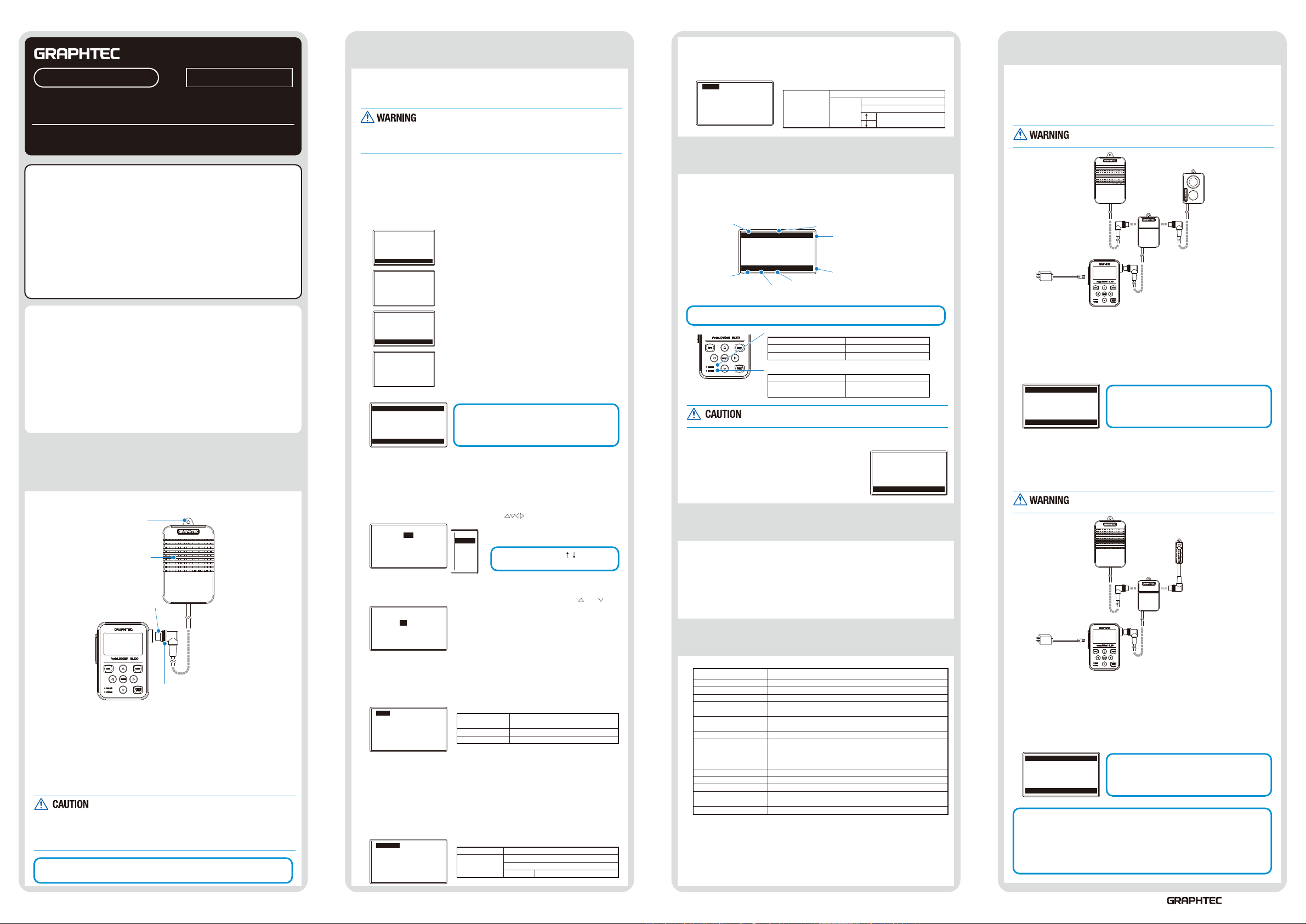
6 Combined Measurement
1. Combined CO2 sensor and illumination / ultraviolet sensor
measurement
Composite measurement can be done by using the branch adapter for GS
(GS-DPA) and the illumination / ultraviolet sensor (GS-LXUV) (each sold
separately).
If the CO2 sensor (GS-CO2) is included in the assembly, it
cannot be powered with batteries.
CO2 Sensor
(GS-CO2)
Branch adapter for GS
(GS-DPA)
* The Gl100’s power is
provided through a
USB cable
connection
GL100 main module
(1) Screen display menu flow
After connecting the power supply, connect this module and operate it in
accordance with the content displayed on the screen.
* Refer to “2 How To Measure” above and the USER'S MANUAL for the
illumination / ultraviolet sensor.
(2) Free-running screen
ST OP ALM . 1 :2 8
IL LU M: 0
m
UV -A : 0. 01 6
PP
CO 2: 73 6
BA T L AN SD S : 1 .0 s
lx
W
m
Hold down the [QUIT] key (approx. three seconds)
to put the module into standby state.
Press the [ENTER] key while in standby state to
return to the free-running screen.
2. Combined CO2 sensor and temperature and humidity
sensor measurement
Composite measurement can be done by using the branch adapter for GS
(GS-DPA) and the temperature and humidity sensor (GS-TH) (each sold
separately).
If the CO2 sensor (GS-CO2) is included in the assembly, it
cannot be powered with batteries.
CO2 Sensor
(GS-CO2)
Branch adapter for GS
(GS-DPA)
* The Gl100’s power is
provided through a
USB cable
connection
(1) Screen display menu flow
After connecting the power supply, connect this module and operate it in
accordance with the content displayed on the screen.
* Refer to “2 How To Measure” above and the USER'S MANUAL for the
temperature and humidity sensor.
(2) Free-running screen
ST OP ALM . 1 :2 8
TE MP : + 26 .1 6℃
HU M. : +3 7. 3%
DE WP : + 10 .3 0℃
PP
CO 2: 73 6
BA T L AN SD S : 1 .0 s
< Extension cable >
The module can be used approx. 1.5 m away from the GL100 by using an
extension cable for GS (GS-EXC). However, you cannot connect and use multiple
extension cables.
CAUTION
It is not possible to be used by connecting two same sensors.
GL100 main module
m
Hold down the [QUIT] key (approx. three seconds)
to put the module into standby state.
Press the [ENTER] key while in standby state to
return to the free-running screen.
Illumination
/ ultraviolet sensor
(GS-LXUV)
Temperature and
humidity sensor
(GS-TH)
503-10 Shinano-cho, Totsuka-ku Yokohama
244-8503, Japan
August 1, 2014
 Loading...