

Page 1
GS-4VT-UM-151
GS-4VT
For GL100
4ch Voltage / Temperature Terminal
USER’S MANUAL
Thank you very much for buying this GRAPHTEC product.
This product can be used as a measurement terminal (hereafter
"module") that connects to the GL100-N/GL100-WL.
These directions describe preparations and cautions before
measurement.
To ensure safety, please read the operation instructions, etc.
For details on the warnings and how to handle this module, please
read the Quick Start Guide or USER'S MQANUAL included on the
CD-ROM (included in the GL100 packaging)
Confirmation of the exterior
After opening the package, please confirm that there are no
problems (scratches and dirt) on the exterior before use.
Confirmation of the attached items.
User’s manual (this book): 1
•
If by any chance faults are found, please contact the store where you
bought the item.
* Please note that items mentioned in this book may change without
prior notice.
MANUAL-V604309051
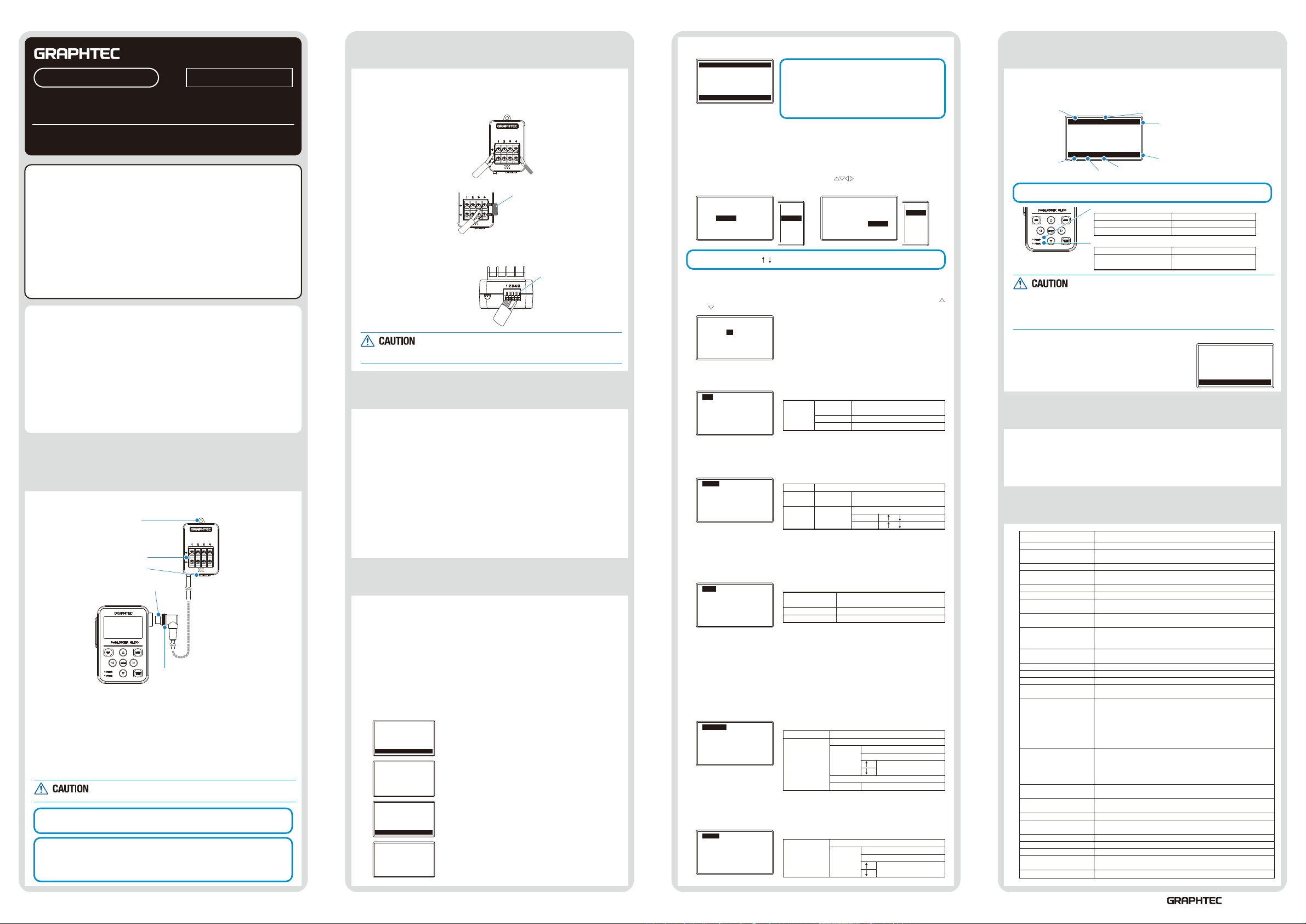
1 Part Names
This section describes the name and function of each part.
1. Hook portion
2. Input terminal
3. Logic input terminal
4. Connector
5. Cable packing
GL100 main module
1. Hook portion ..................
2. Input terminal ................
3. Logic input terminal .......
4. Connector .....................
5. Cable packing ...............
This module is not dustproof or waterproof. Please use it
in a proper usage environment.
After connecting the GL100 to modules or sensors, please always check/set the
time and date.
< Extension cable >
The module can be used approx. 1.5 m away from the GL100 by using an
extension cable for GS (GS-EXC). However, you cannot connect and use multiple
extension cables.
Used to mount to a wall.
Used to connect voltage input or
thermocouple.
Used to apply logic input.
Used to connect to the connector on the
GL100 module.
This packing is used when connecting the connector.
2 How To Connect 5 Recording
We will now explain how to connect the signal input cable.
1. Voltage input
Make sure to pay attention to the + and
– terminals when connecting it.
+: High-voltage terminal
(terminal input on the input
signal’s high-voltage side)
-: Low-voltage terminal
(terminal input on the input
signal’s low-voltage side)
3. Current input
Attach shunt
resistance when
measuring the current
input.
4. Logic / pulse input
+: No. 1 to No. 4:
High-voltage terminal
(terminal input on the input
signal’s high-voltage side)
-: G: Low-voltage terminal
(terminal input on the input
signal’s low-voltage side)
G is the GND terminal for this module.
•
For the maximum input voltage, refer to “3 Regarding
•
Maximum Input Voltage.”
3
Regarding Maximum Input Voltage
To avoid break-downs or short-circuiting accidents, please
make sure to abide by the items written below.
In case the input voltage exceeds the specifications, the circuit at the input
part will break down. Please don't input it.
<Input terminal (+) / Input terminal (-) interval>
Maximum input voltage: DC60Vp-p
<Input terminal (-) /Input terminal (-) interval>
Maximum input voltage: 60Vp-p
<Input terminal (-) /GND terminal interval>
Maximum input voltage: DC60Vp-p
Withstand voltage: 350Vp-p/1min.
Logic/Pulse
<Input terminal (+) / GND terminal interval>
Maximum input voltage: DC24V
4
How To Measure
1. Power supply
(Refer to Quick Start Guide or USER’S MANUAL.)
Connect this module while power is being supplied to the GL100 by a battery
or USB cable.
2. Start-up and operation
(1) Screen display menu flow
After power-on, the GL100 is ready for operation by holding down [MENU] key.
When the module is connected, “Module Type Recognition” screen is displayed.
When the module is not connected, “Module Unconnected State” screen is
displayed.
Operate in accordance with the displayed instructions.
S EN SO R ER RO R !!
P le as e co nn e ct
th e se ns or
QU IT k ey t o P ow er O ff
BA T LA N
”P l ea s e w a it ”
GL 10 0- 4V T
S le ep in g! !
E NT ER k ey t o s ta rt
QU IT k ey t o P ow er O ff
BA T LA N
G L 10 0 - 4V T
I n it i a li z in g!!
Module unconnected state
<Operation>
Connect the module.
Recognition of module types
Standby state
<Operation>
Press [ENTER] key.
Module start-up
2. Thermocouple input
Connect thermocouple
to the + and – terminals.
Thermocouple
Shunt resistance
E.g.
For 4-20mA, add 250Ω
(±0.1%) resistance and
measure with a 1-5V range.
* For shunt resistance, use the
B-551 (option).
When inserting the
cable, insert it while
pressing here.
(2) Free-running screen
ST O P AL M . 1 :2 8
+ 3 4 . 1 ℃ L : O F F
+0 . 0 0 0 1 V L : O F F
+0 . 0 5 0 0 V L : O F F
+ 0 . 0 5 V L : O F F
BA T L A N S D S : 1 .0 s
3. Setting
Hold down the [QUIT] key (approx. three seconds)
to put the module into standby state.
When running on batteries, the module will
automatically go into standby state after three
minutes of no operation.
Press the [ENTER] key while in standby state to
return to the free-running screen.
(1) Setting screen operation
Item selecting screen
Press the [MENU] key on the free-running screen to go to the setting
screen.
<How to set>
Select the item with the directional keys ( ) and press the [ENTER]
key.
[A M P] 1 /1 0
CH I np u t R a ng e
AL L : T EM P ▽ T C -K ▽
1: TE M P▽ T C- K ▽
2: DC - V▽ 1 V▽
3: TE M P▽ T C- K ▽
4: TE M P▽ T C- K ▽
If the submenu shows then there are selections in those directions.
D C -V
T E MP
O f f
[A M P] 1 /1 0
CH I np u t R a ng e
AL L : T EM P ▽ T C -K ▽
1: TE M P▽ T C- K ▽
2: DC - V▽ 1 V▽
3: TE M P▽ T C- K ▽
4: TE M P▽ T C- K ▽
↑
1 V
2 V
5 V
1 0 V
2 0 V
↓
Numerical entry screen
<How to set>
Numbers can be inputted by increasing or decreasing the value with the
and keys.
[D a te / Ti m e] 7 /1 0
Ty p e: YY : MM : DD ▽
Da t e: 20 1 4- 0 1- 0 4
Ti m e: 0 3 :1 8 :2 6 ▽
(2) AMP setting
Select the 4ch measurement content then select the voltage range.
[A M P] 1 /1 0
CH I np u t R a ng e
AL L : D C- V ▽ 5 0 V▽
1: DC - V▽ 5 0V ▽
2: DC - V▽ 5 0V ▽
3: DC - V▽ 5 0V ▽
4: DC - V▽ 5 0V ▽
AMP input condition settings (4ch)
Range 20, 50, 100, 200, 500mV,
DC-V
TEMP
Off
1, 2, 5, 10, 20, 50V, 1-5V
TC-K, TC-T
(3) LOGIC setting
Select the 4ch logic measurement content. When setting the pulse, select
the slope if new logic is “on.”
[L O GI C ] 2 /1 0
In p ut Mo d e: Of f ▽
CH : In p ut Sl o pe
1:
2:
3:
4:
LOGIC input condition settings (4ch)
Off
LOGIC
Pulse
Input
Slope
Input
Slope
Off, On
Off
Counts H, L
Inst. H, L
(4) DATA setting
Set the Sampling and Capture Mode those will be recorded to the data
recording media.
The recorded data’s size will be displayed in the information for the SD
card being recorded to. Please take note of it.
[D A TA ] 3 /1 0
Sa m pl i ng : 1s ▽
Ca p tu r e M OD E :C O NT . ▽
Ca p tu r e D IS T :S D C a rd ▽
Fr e e C AP A :4 9 81 8 0
DATA recording condition setting
Sampling
Capture MODE
Capture DIST
500 ms, 1, 2, 5, 10, 20, 30s.
1, 2, 5, 10, 20, 30, 60 min
CONT, 1 Hour, 24 Hour
Memory, SD card
(5) TRIGGER setting
Select the conditions for beginning data recording after measurement starts.
Off :
Pressing the [START/STOP] key on this module will start/stop recording.
Start : The recording will start with the trigger source conditions after
pressing the [START/STOP] key.
The recording will stop after pressing the [START/STOP] key.
Stop : The recording will start after pressing the [START/STOP] key
and will be stopped with the trigger source conditions.
[T R IG G ER ] 4 /1 0
TR I G S et t in g :O f f▽
TR I G S ou r ce : Of f ▽
TRIGGER capture condition settings
TRIG setting
TRIG Source
Off, Start, Stop
Off
Level Off
/ Mode Level
H Value setting
L
Alarm
Date Date, Time
*
The level depends on the setting range.
(6) ALARM setting
Set the alarm information. The parameters will vary depending on the
setting range. Please set the number level.
[A L AR M ] 5 /1 0
Al a rm : Of f ▽
ALARM settings
Alarm Off
Level Off
/ Mode Level
H Value setting
L
* The level depends on the setting range.
(1) Recording
Press the [START/STOP] key to start measuring with the set conditions.
After pressing [START] key, when the module is in awaiting recording start,
“ARMED” is displayed, and then when recording is started, "REC" is displayed.
RE C . A L M. 1 :2 8
+ 3 4 . 1 ℃ L : O F F
+0 . 0 0 0 1 V L : O F F
+0 . 0 5 0 0 V L : O F F
+ 0 . 0 5 V L : O F F
When battery
replacement
is required, “BAT”
is displayed.
The module’s status is shown with the lamp display.
BA T L A N S D S : 1 .0 s
LAN: displayed when the wireless LAN connection is enabled.
STATUS (Orange)
Accessing SD card
Low battery
Alarm active
POWER(Green)
Power supplying
Wireless LAN connection
possible status
When accessing an SD card, do not remove the SD card. The
•
data may not write properly or the SD card may be damaged.
When “low battery” is displayed, replace the battery or
•
connect the USB interface to supply power as soon as
possible. Caution: Batteries cannot be replaced when
recording data. Replace them after the recording has finished.
(2) Recording completion
• Press the [START/STOP] key to stop measuring.
• The screen display will change to the standby
screen display.
• Press [ENTER] key to change to the
free-running screen display.
6 How To Confirm The Data
Check the recorded data with the application software included with this
module using the method below (for details, refer to the USER'S MANUAL).
(1) Connect the USB interface and check the online data
(2) Insert the SD card into PC and check the data directly
(3) Check the data directly from PC via wireless LAN
7 Specifications
Item
Measurement data
Measurement channels
Input method
Measurement voltage range
Measured voltage accuracy
Input resistance
Temperature coefficient
Allowable signal source
resistance
Maximum input voltage
Withstand voltage
Insulation resistance
Common mode rejection ratio
Noise
Measurement
temperature range
Measured temperature
accuracy
Logic/Pulse Input
Pulse measurement
range
Room temperature
compensation
Temperature unit
Sampling interval
Alarm
Cable Length
Usage environment
External dimensions
[W×D×H] (approximate)
Weight (approximate)
Voltage / Temperature/Logic, Pulse count (Instant, Accumulation)
Voltage/Temperature 4 channels
Logic/Pulse count 4 channels
Scan system by Photo-MOS relay, All-channel isolated input
20, 50, 100, 200, 500 mV
1, 2, 5, 10, 20, 50V 1-5V F.S.
0.15 % of F.S.
1 MΩ ±5%
Gain: ±0.01 % of F.S./℃
Zero: ±0.02 % of F.S./℃
300 Ω or less
Input terminal + / - interval : 60Vp-p
Input terminal / Input terminal interval : 60Vp-p
Input terminal / GND interval : 60Vp-p
Input terminal / Input terminal interval : 350 Vp-p 1 min.
Input terminal / GND interval : 350Vp-p 1 min.
Input terminal / GND interval : 50MΩ or more (at DC500V)
90 dB or more (50/60 Hz signal source 300Ω or less)
48 db or more (+/- at short)
<Thermocouple> K -200 to 1370℃
<K-type thermocouple>
-200≤TS≤-100 ±(0.05% of rdg +2.0℃)
-100<TS≤1370℃ ±(0.05% of rdg +1.0℃)
<T-type thermocouple>
-200≤TS≤-100 ±(0.1% of rdg +1.5℃)
-100<TS≤400℃ ±(0.1% of rdg +0.5℃)
Reference junction compensation accuracy : ±0.5ºC
Input voltage range: 0 to +24V (One line ground input)
Input signal: No-voltage contact (a contact, b contact, NO, NC)
Input threshold voltage: approx. +2.5V
Hysteresis: approx. 0.5 V (+2 to +2.5V)
Instant : max. 200C / Sampling
Accumulation: max. 65535C
ON / OFF
Select from °C (Celsius) / °F (Fahrenheit)
0.5, 1, 2, 5, 10, 20, 30 sec.
1, 2, 5, 10, 20, 30, 60 min.
OFF / Level
approximate 20 cm
-10 to 50°C, 80% RH or less (non-condensing)
46 × 66 × 35.5 mm (not including protruding parts)
85 g
When alarm occurs, “ALM” is displayed.
Current time
Note: The current time display can
be switched to the elapsed
time with the [QUIT] key when
recording.
“SD” is displayed during accessing the SD card.
Sampling interval
Access light
Flash once every 5 seconds
Flash once every 10 seconds
Flash once every 10 seconds
Flash once every 5 seconds
Contents
T -200 to 400℃
Open collector, voltage input
GL 1 00 - 4V T
S l ee p in g !!
E N TE R k e y t o s ta r t
QU I T k ey to Po w er Of f
BA T L A N
503-10 Shinano-cho, Totsuka-ku Yokohama
244-8503, Japan
August 1, 2014
 Loading...