

Page 1

GL980
USER’S MANUAL
MANUAL NO.GL980-UM-151
Page 2

Page 3

To Ensure Safe and Correct Use
To Ensure Safe and Correct Use
To ensure safe and correct use of this device, read this manual thoroughly before use.
•
After having read this manual, keep it in a handy location for quick reference as needed.
•
Do not permit small children to touch this device.
•
The following describes important points for safe operation. Please be sure to observe them strictly.
•
Conventions Used in This Manual
To promote safe and accurate use of this device as well as to prevent human injury and property damage,
safety precautions provided in this manual are ranked into the ve categories described below. Be sure you
understand the difference between each of the categories.
This category provides information that, if ignored, is
DANGER
highly likely to cause fatal or serious injury to the operator.
WARNING
CAUTION
HIGH
TEMPERATURE
ELECTRICAL
SHOCK
Description of Safety Symbols
The symbol indicates information that requires careful
attention (including warnings). The specic point requiring
attention is described by an illustration or text within or next to
the symbol.
This category provides information that, if ignored, is
likely to cause fatal or serious injury to the operator.
This category provides information that, if ignored, could
cause physical damage to this device.
This category provides information that, if ignored, is
likely to cause burns or other injury to the operator due to
contact with high temperature.
This category provides information that, if ignored, is
likely to expose the operator to electrical shock.
The symbol indicates an action that is prohibited. Such
prohibited action is described by an illustration or text within or
next to the symbol.
The symbol indicates an action that must be performed.
Such imperative action is described by an illustration or text
within or next to the symbol.
i
Page 4

Page 5

Introduction
Introduction
Thank you for purchasing the GL980 midi LOGGER.
Please read this manual thoroughly before attempting to use your new product to ensure that you use it correctly
and to its full potential.
Notes on Use
Be sure to read all of the following notes before attempting to use the GL980 midi LOGGER.
1. Note on the CE Marking
The GL980 midi LOGGER complies with the following standards.
• EN 61326-1 Class A standard based on the EMC directive (2014/30/EU)
• EN 61010-1:2010 3rd standard based on the LVD directive (2014/35/ EU)
Although the GL980 complies with the above-mentioned standards, be sure to use it correctly in accordance
with the instructions and notes provided in this manual.
Moreover, use of the GL980 by incorrect procedures may result in damage to the GL980 or may invalidate its
safeguards. Please conrm all of its notes regarding use and other related information to ensure correct use.
2. Warning
This is a Class A product according to the EMC directive. In a domestic environment, this product may cause
radio interference or may be affected by radio interference to the extent that proper measurement cannot be
performed.
3. Notes for Safe Operation
(1) Be sure to use the Graphtec-supplied AC adapter. In environments where there is a lot of noise or where
the power supply is unstable, we recommend that you ground the GL980.
(2) When a high-voltage signal cable has been connected to the main unit’s analog signal input terminal,
avoid touching the leads of the input terminal’s signal cable to prevent electrical shock due to high voltage.
(3) Ensure that the GL980 power source is positioned so that it can easily be disconnected.
(4) Do not input the voltage that exceeds the specication of this device.
• If a voltage exceeding the specied value is connected, the semiconductor relay in the input section will
get damaged. Never input a voltage exceeding the specied value even for a moment. It will cause a re.
• Have an enough margin from the specication of withstanding voltage when using this device, it have to
consider a noise and change in measurement voltage.
• Conrm that the device is not damaged before the input cable is connected to the input terminal.
• Please take care of static electricity when connecting an input cable or a thermocouple.
• Do not touch the tip of thermocouples with bare hand after the thermocouples are connected to the
terminal of this device if the tip of thermocouples is not insulated.
The static electricity from a human body will cause damage to the device.
• Do not put the tip of thermocouples to an object which contains static electricity if the tip of thermocouples
is not insulated. The static electricity of object will cause damage to this device.
• Do not put the tip of thermocouples to an object which contains leaked high voltage of chassis or metal
etc. if the tip of thermocouples is not insulated.
The leaked high voltage from object will cause damage to the device.
• We recommend that the insulation tape puts on the tip of thermocouples before connecting the
thermocouples to the input terminals.
This will protect this device from the static electricity and the leaked high voltage.
I
Page 6

Introduction
4. Notes on Functions and Performance
(1) Be sure to connect the main unit to an AC or DC power supply that conforms to the rated range.
Connecting the device to a non-rated power supply may cause the main unit to overheat and break down.
(2) Do not block the vent on the main unit.
Continued operation with the blocked vent may cause the main unit to overheat and break down.
(3) To avoid malfunctions and other damage, avoid using GL980 in the following locations.
• Places exposed to high temperature and/or high humidity, such as in direct sunlight or near
heatingequipment.
Allowable temperature range: 0 to 40°C (When AC adapter or battery is operated)
: 15 to 25°C (Battery being charged)
Allowable humidity range: 5 to 85%R.H., non-condensing
• Locations subject to excessive salt spray or heavy fumes from corrosive gas or solvents.
• Excessively dusty locations.
• Locations subject to strong vibrations or shock.
• Locations subject to surge voltages and/or electromagnetic interference.
(4) If the main unit becomes soiled, wipe clean using a soft, dry cloth. Use of organic solvents (such as
thinner or benzene) causes deterioration and discoloration of the outer casing.
(5) Do not use GL980 in the vicinity of other devices which are susceptible to electromagnetic interference.
(6) Measured results may not conform to the stated specications if GL980 is used in an environment which
is subject to strong electromagnetic interference.
(7) Insofar as possible, position GL980 input signal cables away from any other cables which are likely to be
affected by electromagnetic interference.
(8) For stabilized measurement, allow GL980 to warm up for at least 30 minutes after turning the power on.
II
Page 7

Introduction
Notes on the Use of This Manual
(1) All rights reserved. No part of this publication may be reproduced, stored in a retrieval system, or transmitted, in
any form or by any means, without the prior written permission of Graphtec Corporation.
(2) The specications and other information in this manual are subject to change without notice.
(3) While every effort has been made to supply complete and accurate information about this product, please
address any inquiries about unclear information, possible errors, or other comments to your sales representative
or nearest Graphtec vendor.
(4) Notwithstanding the preceding paragraph, Graphtec Corporation assumes no liability for damages resulting
from the use of the information contained herein or of the product.
About Registered Trademarks
Microsoft and Windows are registered trademarks or trademarks of Microsoft Corporation in the U.S. and
elsewhere.
Other company names and product names included in this manual are registered trademarks or trademarks of
their respective companies.
Copyright
All copyrights regarding this manual belong to Graphtec Corporation.
III
Page 8

Page 9

CONTENTS
To Ensure Safe and Correct Use ................................................i
Introduction .................................................................I
Notes on Use .................................................................I
Notes on the Use of This Manual ................................................III
About Registered Trademarks ...................................................III
Copyright ...................................................................III
CHAPTER 1 General Description
1.1 Overview .............................................................1-2
1.2 Features .............................................................1-2
1.3 Operating Environment .................................................1-3
Ambient Operating Conditions ................................................. 1-3
Warming-up Before Use ..................................................... 1-3
Conguration When in Use ................................................... 1-4
1.4 Rubber Protector ......................................................1-5
CONTENTS
1.5 Notes on Temperature Measurement .....................................1-6
1.6 Notes on Using the Monitor .............................................1-6
1.7 Changing the Display Language .........................................1-6
CHAPTER 2 Checks and Preparation
2.1 Checking the Outer Casing ..............................................2-2
2.2 Checking for Accessories ...............................................2-2
Standard Accessories ....................................................... 2-2
2.3 Nomenclature and Functions ............................................2-3
2.4 How to attach the tilt stand ............................................. 2-4
2.5 How to detach the rubber protector ......................................2-5
How to attach the rubber protector ............................................. 2-5
How to remove the rubber protector ............................................ 2-6
2.6 Connecting the Power Cable and Turning the Power on ......................2-7
2.7 Connecting the Input Signal Cables ......................................2-9
2.8 Logic Alarm Cable Connection and Functions .............................2-11
2.9 Mounting the SD Card .................................................2-15
2.10 Installing USB Memory ................................................2-17
2.11 Connecting to a PC ...................................................2-18
2.12 Using the Battery Pack (B-569 : Option) ..................................2-20
2.13 Connecting the Humidity Sensor ........................................2-23
2.14 Precautions to Observe When Taking Measurement ........................2-24
2.15 Noise Countermeasures ...............................................2-26
2.16 When Fixing This Device. . . . . . . . . . . . . . . . . . . . . . . . . . . . . . . . . . . . . . . . . . . . . . .2-27
2.17 Setting the Date and Time. . . . . . . . . . . . . . . . . . . . . . . . . . . . . . . . . . . . . . . . . . . . . .2-28
C-1
Page 10

CONTENTS
CHAPTER 3 Settings and Measurement
3.1 Window names and functions ...........................................3-2
3.2 Key Operation .......................................................3 -17
3.3 Description of the display mode ........................................3-27
(1) Y-T waveform display ..................................................... 3-27
(2) Logging display/real time statistical calculation display ...........................3-37
(3) XY waveform display .....................................................3-39
3.4 Operation Modes .................................................... 3-52
3.5 Setting Menus ...................................................... 3-56
(1) AMP settings ............................................................ 3-56
(2) DATA settings ...........................................................3-69
(3) DISP settings ...........................................................3-82
(4) TRIG settings ...........................................................3-94
(5) Interface settings ....................................................... 3 -105
(6) OTHER settings ........................................................ 3-112
(7) FILE menu ............................................................ 3-118
(8) Data replay menu .......................................................3-130
3.6 WEB Server Function ................................................3-13 4
3.7 List of Error Codes ..................................................3-13 9
CHAPTER 4 Specication
4.1 Standard Specications ................................................4-2
Internal RAM .............................................................. 4-3
Internal memory ............................................................ 4-3
USB Memory slot ........................................................... 4-3
SD card .................................................................. 4-3
PC I/F .................................................................... 4-4
Monitor ................................................................... 4-4
Input section ..............................................................4-5
4.2 Function Specications ................................................4-7
Function Specicationsr ..................................................... 4-7
Trigger Functions ........................................................... 4-8
Alarm Functions ............................................................ 4-8
External Input/Output Functions ............................................... 4-9
4.3 Accessories/Optional Accessories . . . . . . . . . . . . . . . . . . . . . . . . . . . . . . . . . . . . . .4 -10
Control Software .......................................................... 4-10
Standard Accessories ...................................................... 4-10
Battery Pack (Option) ....................................................... 4-10
List of Options .............................................................4 -11
4.4 External Dimensions ..................................................4-12
INDEX ..............................................I-1
C-2
Page 11

CHAPTER 1 General Description
CHAPTER 1 General Description
This chapter provides a general description of this device and its features.
PRODUCT SUMMARY
1.1 Overview
1.2 Fe atures
1.3 Operating Environment
1.4 Rubber Protector
1.5 Notes on Temperature Measurement
1.6 Notes on Using the Monitor
1.7 Changing the Display Language
1-1
Page 12

CHAPTER 1 General Description
1.1 Overview
GL980 is a compact, lightweight, multi-CH, and multi-purpose data logger with a 7-inch color display.
GL980 can capture up to ± 500V with maximum 1 μs sampling.
Large capacity of measured data can be saved directly in the internal memory, SD card, or USB memory.
As PC interface is equipped with USB and Ethernet, the system can be congured in accordance to
application environment. Since it is equipped with the WEB server and the FTP server as part of the
Ethernet function, you can monitor and transfer data remotely.
1.2 Features
Input
Using M3.5 screw terminal or BNC terminal, input terminal can easily be wired.
•
Can measure voltage, temperature, effective value (RMS).
•
Display & Operation
With this device’s high-resolution 7-inch TFT color liquid crystal display, you can conrm the waveforms of
•
measured data and channel settings at a glance.
Easy operation is achieved through a straightforward menu structure and key allocation which resembles
•
a mobile phone.
Data Capture
This device can capture at up to 1 μs capturing interval to the Internal RAM .
•
Measure for an extended period at high speed to the Internal RAM with 4M word per CH.
•
It is useful the Internal RAM can be divided up to 8 segments to repeat measurement in continuous mode.
It can to capture up to 4GByte data to the internal memory, SD memory card and USB memory.
•
Large capacity of measured data can be saved directly into the internal memory, SD card, or USB
•
memory.
Using SD card or USB memory as additional memory, measure for an extended period while backing the
•
data up for additional storage media.
The new ring memory capture function maintains latest data even after capturing for a long term. (You
•
need to set how long you want to keep the data.)
GL980 is equipped with the relay capturing function, and 4GByte or more data can be saved by switching
•
the to the other le without missing any data.
Data Control & Processing
The application software lets you set conditions and monitor data on a PC in real time.
•
With the USB drive mode function, you can recognize the GL980 internal memory and SD card as an
•
external drive from a PC.
(Connect the GL980 to the PC and turn the GL980 power while holding down the [START] key.)
The WEB server function enables control and monitoring from a remote location without using dedicated
•
software.
The FTP client function enables backup of measurement data to the FTP server.
•
The NTP client function enables synchronization of the time with the NTP server.
•
1-2
Page 13

CHAPTER 1 General Description
1.3 Operating Environment
This section explains the operating environment for this device.
Ambient Operating Conditions
(1) Ambient temperature and humidity (Use within the following range.)
• Temperature range: 0 to 40°C (When AC adapter or battery is operated)
: 15 to 25°C (Battery being charged)
• Humidity range: 5 to 85% R.H. (non-condensing)
(2) Environment (Do not use in the following conditions.)
• A Location exposed to direct sunlight
• Locations exposed to salty air, corrosive gases, or organic solvents
• Dusty locations
• Locations subject to vibration or impact
• Locations subject to voltage surge or electromagnetic interference such as lightning or electric furnaces
(3) Installation category (over-voltage category)
• This device belongs to Installation Category II dened in IEC60664-1.
• Never use this device for Installation Category III or IV.
(4) Measurement category
• This device is not available for Measurement category II, III and IV.
If condensation occurs...
•
Condensation occurs in the form of water droplets on the device surfaces and interior when this device
is moved from a cold to a warm location. Using this device with condensation will cause malfunctioning.
Wait until the condensation has disappeared before turning the power on.
Warming-up Before Use
This device should be allowed to warm up with the power turned on for approximately 30 minutes to ensure
that it operates according to the specied performance.
1-3
Page 14

CHAPTER 1 General Description
Conguration When in Use
When using the device, be sure to set the device vertically, or use the tilt foot and tilt stand to operate the
device.
<Usage Conguration>
Vertical state
Tilt foot
Tilt stand
Inclined state
Do not block the air vent on this device, as this will cause malfunctioning.
•
Measurement accuracy may not be accurate if the system is used in a condition other than described
•
above.
If using this device in a tilted state, please use both tilt foot and tilt stand for this device to prevent it
•
from falling.
90°
Tilt stand
1-4
Page 15

1.4 Rubber Protector
To remove a battery pack, remove the rubber protector rst.
This manual describes in the state without the rubber protector.
CHAPTER 1 General Description
Without rubber protector
With rubber protector
1-5
Page 16

1.5 Notes on Temperature Measurement
Please observe the following precautions when taking temperature measurement.
Do not block the air vents. Always provide a space of at least 30 cm on all sides of this device.
•
For stabilized temperature measurement, allow this device to warm up for at least 30 minutes after turning
•
the power on.
Exposure of the input terminals to direct drafts, direct sunlight, or abrupt changes in temperature may
•
impair the equilibrium of the input parts and result in measurement errors. To measure temperature in
such an environment, take appropriate countermeasures such as changing the installation site of this
device or properly ground the equipment.
To conduct measurement in noisy environments, connect this device’s GND terminal to ground (Refer to
•
“2.15 Noise Countermeasures”.).
If the measured value uctuates due to noise, set FILTER to other than OFF in the input setting menu of
•
this device.
1.6 Notes on Using the Monitor
The monitor is an LCD display unit. The display will vary depending on the operating environment.
If a screen saver function is used, it will operate and clear the screen if no operations are performed
during the preset time. When pressing any of the operation keys, the screen saver is released and the
screen display is started.
Condensation may form on the LCD screen if this device is moved from a cold to a warm location. If this
•
occurs, wait until the LCD screen warms up to room temperature.
The LCD screen is manufactured to extremely high precision. Black dots may appear, or red, blue, and
•
green dots may appear. Likewise, lines may appear when viewed from certain angles. These phenomena
are due to the LCD screen construction, and are not signs of a defect.
1.7 Changing the Display Language
You can select the language displayed on the screen. The default display language is set to English for
worldwide market. To change the display language, see the instructions in "OTHER:Language".
Page 17

CHAPTER 2 Checks and Preparation
CHAPTER 2 Checks and Preparation
This chapter provides how to check the device's external casing and accessories, and how to prepare the
device for operation.
PRODUCT SUMMARY
2.1 Checking the Outer Casing
2.2 Checking for Accessories
2.3 Nomenclature and Functions
2.4 How to attach the tilt stand
2.5 How to detach the rubber protector
2.6 Connecting the Power Cable and Turning the
Power on
2.7 Connecting the Input Signal Cables
2.8 Logic Alarm Cable Connection and Functions
2.9 Mounting the SD Card
2.10 Installing USB Memory
2.11 Connecting to a PC
2.12 Using the Battery Pack (B-569 : Option)
2.13 Connecting the Humidity Sensor
2.14 Precautions to Observe When Taking
Measurement
2.15 Noise Countermeasures
2.16 When Fixing This Device
2.17 Setting the Date and Time
2-1
Page 18

CHAPTER 2 Checks and Preparation
2.1 Checking the Outer Casing
After unpacking, check this device's outer casing before use. In particular, please check for the following:
Surface scratches
•
Other aws such as stains or dirt
•
2.2 Checking for Accessories
After unpacking, check that the following standard accessories are included.
Standard Accessories
Item Remarks Quantity
Quick Start Guide GL980-UM-85x 1
CD-ROM User's Manual, Application software 1
TO ENSURE SAFE AND
CORRECT USE
AC cable/AC adapter 100 to 240 VAC, 50/60 Hz 1
Ferrite core For attaching each cable 4
M3.5 Flat screw For thin-type thermocouple 20
Tilt stand Tilt stand x2, M4 x 5 screw 2, M4×8 screw 2, specer×3 1
SAFETY PAMPHLET 1
2-2
Page 19

2.3 Nomenclature and Functions
This section describes the names and function of the device.
CHAPTER 2 Checks and Preparation
PC interface terminals
• USB
• LAN
External input/output terminals
• LOGIC/PULSE
• EXT TRIG/SAMP LE
• ALARM/ TRIG
SD CARD
Power jack for humidity sensor
Humidity sensor
(B-530: Option)
Operation status LED
• POWER ON when t he powe r is ON
Blinking while a ccessing to th e
memory
• START ON during da ta capture
• CHARGE ON while the ba tter y is charging
Monitor
Control panel keys
Analog signal input terminals GND terminal
AC adapter jack
Power switch
USB memory te rminal
Battery cover
Two battery pack s (B- 569: op tion)
can be installed.
Label
Tilt stand xing screw
(Screw hole M4, Depth 6)
Tilt foot
2-3
Page 20

CHAPTER 2 Checks and Preparation
2.4 How to attach the tilt stand
When tilt foot is used When tilt foot is not used
(1) Please pay attention to the mounting position and install the tilt foot.
Without Rubber Protector
•
M4 x5
Tilt stand
Fasten with a scr ew from t he
lower hole.
When tilt foot is used When tilt foot is not used
With Rubber Protector
•
Use M4x8 screw and spacer supplied with this device.
Spacer
M4 x 8
Tilt stand
Fasten with a scr ew from t he
lower hole.
Fasten with a scr ew from t he
upper hole.
Fasten with a scr ew from t he
upper hole.
2-4
When tilt foot is used When tilt foot is not used
To prevent possible malfunction, do not block the air vents of this device.
•
If you use this device in other position than described in the above, the measurement accuracy may not
•
meet the specications.
To prevent possible falling, attach both tilt stand and tilt foot for this device.
•
Page 21

2.5 How to detach the rubber protector
How to attach the rubber protector
To remove the battery pack, rst remove rubber protector.
(1) Insert one side of this device about half into the Rubber Protector.
CHAPTER 2 Checks and Preparation
(2) Pull the cover over the terminal block and insert the remaining half.
(3) Adjust so that the rubber protector is not out of position.
(4) Make sure that the corners and convexities are properly tted and adjust the protector so that there is no
gap.
2-5
Page 22

CHAPTER 2 Checks and Preparation
How to remove the rubber protector
(1) Open the upper and lower corner of the Rubber Protector on one side of this device as shown below.
(2) Push out the body from the back side.
(3) When both corners of this device are removed from the Rubber Protector, pull the protector over the
terminal block.
(3)
(2)
(1)
(4) Remove the body completely from the Rubber Protector.
2-6
Page 23

CHAPTER 2 Checks and Preparation
2.6 Connecting the Power Cable and Turning the Power on
This section describes how to connect the power cable and turn the power on. The connection method will
vary depending on the type of power supply used.
Connecting to an AC Power Supply
Use the AC cable and AC adapter that are provided as accessories.
Be sure to use the AC adapter that is supplied as a standard accessory.
(1) Plug the AC cable into the AC adapter.
AC adapter
AC cable
(2) Connect the output side of the AC adapter to the connector on this device.
AC adapter cable
(3) Using the at-blade screwdriver, press against the minus (-) button above the GND terminal, while
connecting the grounding cable to this device connect the other end of the cable to ground.
(4) Plug the AC cable into the main power outlet.
(5) Press the power switch to the ON position to start.
Always connect the GND terminal and refer to the TO ENSURE SAFE AND CORRECT USE precautions.
This device must be grounded even when connected to other devices and sharing a common ground level.
2-7
Page 24

CHAPTER 2 Checks and Preparation
Connecting to a DC Power Supply
Use the DC drive cable (B-514: option).
Use a power supply within 8.5 to 26.4 VDC range.
•
For DC drive cable, please be sure to use B-514 power cable.
•
(1) Congure the tip of the DC drive cable (B-514: 2m) to connect to the DC power supply.
(2) Connect the DC output side to the power supply connector on this device.
White (+ side) Shielded le ad (- side)
DC drive cable
(B-514: Option)
(3) Connect the DC input side to the DC power supply.
Be sure to check the polarity of the wire tips when performing wiring.
(4) Press the power switch to the ON position to start.
2-8
Page 25

2.7 Connecting the Input Signal Cables
This section describes how to connect the input signal cables.
When wiring, turn off the signal supply source to prevent electric shock.
Also, position the input cables away from any power lines and ground cables.
Terminal Conguration and Signal Types
CH8 CH1
CHAPTER 2 Checks and Preparation
High potential input terminal
Low potential input terminal
BNC connectorScrew terminal
The screw terminal and the BNC connector are internally connected. You
can measure with either input.
When wiring, turn off the signal supply source to prevent electric shock.
Also, wire as far as possible from the power line and ground cable.
The screw terminals of the same CH and the BNC
connector are connected.
Do not input signals to the screw terminal and
BNC connector
Screw terminal
GL980
BNC connector of the same CH at the same time.
If a signal is input at the same time, the
measurement target device may become
damaged.
When wiring, turn off the signal supply source to prevent electric shock. When applying a voltage of 60V or
more, please use an insulated BNC cable (RIC-142/143/147: Option) sold separately to prevent any electric
shock.
2-9
Page 26

CHAPTER 2 Checks and Preparation
Connection diagram
DC voltage input Thermocouple input Current input
+ −
DC voltage
Please wire so that the main unit is not tugged by the signal input cable.
If the main unit is pulled, there is a danger where the device will tip over.
+ −
Compensating lead wire
+ −
DC current
Ex: The current is conver ted to t he volta ge usin g
the shun t register.
For 4 to 20 mA current input, install 25 0 ohms
(0.1%) resist er for co nvert ing 1 to 5V.
+ .....................................High potential terminal (The high potential side of the input signal is input.)
- ......................................Low potential terminal (The low potential side of the input signal is input.)
Item Description
Input conguration Isolated input
Measurement range 20, 50, 100, 200, 500 mV/F.S.; 1, 2, 5, 10, 20, 50, 100, 200, 500V/F.S.
1-5V/F.S
Thermocouples K, J, E, T, R, S, B, N, W (WRe 5-26)
A/D resolution 16-bit (Effective resolution: Approx. 1/40,000 of ± range)
Filter Off, Line, 5, 50, 500, 5k, 50 kHz
Input cable
This device conforms to the EMC directive when the core is attached to the input cable.
Please attach the supplied core to the input cable as shown in the gure below.
* Even without a core, measurement accuracy is not affected.
the same time
In case of thermocoupleWhen installing to 1 or 2When installing more than one (3 to 4 pcs.) at
Screw terminal
Recommended tightening torque of screw terminal is max. 6kgf/cm.
If the thermocouple tends to come off due to the use of a thin-type thermocouple, replace it with the supplied
M3.5 at screw.
2-10
Page 27

CHAPTER 2 Checks and Preparation
2.8 Logic Alarm Cable Connection and Functions
This section describes how to connect the logic alarm cables and the functions of cable.
When wiring, turn off the signal supply source to prevent electric shock.
Also, position this input cables away from any power lines and ground cables.
The Input/output cable for GL (B-513: Option) allows logic/pulse input, external trigger input, and alarm/
trigger signal output.
Connect the Input/output cable for GL (B-513: Option) to the external input/output terminal as shown below.
Input /output cable for GL
(B-513: Option)
Logic/Pulse Input Specications
Item Description
Number of input channels 4
Input voltage range 0 to +30 V max. (single-ended ground input)
Threshold level Approx. +2.5 V
Hysteresis Approx. 0.5 V (+2.5 to +3 V)
* Switch between logic and pulse input.
Trigger Input/External Sampling Input Specications
Item Description
Number of input channels 1
Input voltage range 0 to +30 V max. (single-ended ground input)
Threshold level Approx. +1.9 V
Hysteresis Approx. 0.2 V (+1.9 to + 2.1 V)
2-11
Page 28

CHAPTER 2 Checks and Preparation
Alarm Output Specications
Item Description
Number of Output channels 4
Output format Open collector output
Trigger output time When a start trigger or a stop trigger is detected, a pulse of approx.500 μs
When the power is turned OFF or ON, the device temporarily becomes at an alarm state.
Output 1 is used for alarm output and trigger output by switching.
+5 V, 10 kΩ pull-up resistance
* For details of alarm output, refer to the next page.
width is output from the output 1 terminal.
(When setting low active and trigger output)
* When a stop trigger is issued within 1 ms from the start trigger, the trigger
is output at an interval of approx.1 ms.
Trigger output
Trigger output
of star t trigger
Approx. 500μs
Approx. 1ms
Trigger output
of star t trigger
Approx. 500μs
2-12
Page 29

Internal equivalent circuit of I/O circuit
Alarm output
•
+5 V
Maxim um ratings of the transi stor for alarm ou tput
VCEO (Coll ector-em itte r voltag e) : 30 V
IC (Coll ector current) : 0.5A
PC (Collector d issipation) : 0. 2W
* The maximum ratings mu st not be exceeded.
CHAPTER 2 Checks and Preparation
10kΩ
2SC2411K
Logic/pulse input
•
LOGIC/PULSE
GND
Example of external connection
ALARM
Load
GND
+5 V +5 V
10 kΩ
10kΩ
33kΩ
Required for a n induc tive
load such as a rel ay
DC
(5 to 24V)
1kΩ
Comparator
Trigger input /external sampling input
•
+5 V
10 kΩ
TRIGGER/SAMPLE
GND
10kΩ
+5 V
1kΩ
Comparator
2-13
Page 30

CHAPTER 2 Checks and Preparation
Wiring
Cable tips are bare tips. Perform wiring for the necessary functions.
Signal Name Channel Number Wire Color
Logic/Pulse input 1 Orange with red dotted line
Output1 : Alarm output1 / Trigger output * White with red dotted line
Output2 : Alarm output2 White with black dotted line
Output3 : Alarm output3 Yellow with red dotted line
Output4 : Alarm output4 Yellow with black dotted
Trigger input/External sampling input Pink with red dotted line
GND Pink with black dotted line
* Switch between logic and pulse.
* Output 1 is used for alarm output and trigger output by switching.
2 Orange with black dotted line
3 Grey with red dotted line
4 Grey with black dotted line
Shielded
Orange with red dotted line : 1
Orange with black dotted line : 2
Grey with red dotted line : 3
Grey with black dotted line : 4
White with red dotted line : 1
White with black dotted line : 2
Yellow with red dotted line : 3
Yellow with black dotted line : 4
Pink with red dotted line : Trigger input/External sampling input
Pink with black dotted line
Shielded
Logic/Pulse input
Alarm output1 / Trigger output
Alarm output
GND
2-14
Page 31

CHAPTER 2 Checks and Preparation
2.9 Mounting the SD Card
When a SD card is inserted, make sure that the card is not locked. If locked, data will not be recorded.
•
Please do not remove the SD card while accessing the SD card (Device Access display is displayed in
•
"red" and POWER LED blinks.). The captured data may get damaged.
When inserting a large capacity SD card, it may take some time to recognize the device.
•
How to insert the SD card (SD CARD)
Insert the SD card into the SD CARD slot.
(1) Open the SD CARD cover.
Cover
(2) Insert the SD card until it clicks in place.
* Make sure that the SD card is not locked.
* Make sure that the SD card is
not locked.
Lock
SD CARD
x GB
SD card
(3) Close the SD CARD cover.
2-15
Page 32

CHAPTER 2 Checks and Preparation
How to remove the SD card (SD CARD)
(1) Remove SD card after the device access display (SD card) on the device's screen turns green.
(2) Open the SD CARD cover.
(3) The SD card is released by pushing gently on the card. Then, remove the SD card.
While accessing the SD card, the device access indicator (SD card) turns red (and the POWER LED blinks).
Be sure to remove only when the indicator is green.
2-16
Page 33

CHAPTER 2 Checks and Preparation
2.10 Installing USB Memory
When handling USB memory, please pay attention to static electricity.
•
Do not remove the USB memory while it is being accessed (Device access indicator turns red and POWER
•
LED blinks). The captured data may get damaged.
When using HDD and USB memory (4GB or more), please format them using FAT32.
•
How to install USB memory
Install the USB memory in the USB memory slot.
USB memory
When the USB memory is installed in this device, please handle with care.
<USB memory specications>
• Power supply: +5V
• Consumption current: 250 mA or less
• Capacity: No limit (however, up to 4GByte for 1 le)
* USB memory with security function such as ngerprint authentication or USB memory without shell (metal
part) on the connector part cannot be used.
* USB bus power type HDD cannot be used. Format the HDD to FAT32.
For the latest information and support information, please check the following URL.
http://www.graphtec.co.jp
2-17
Page 34

CHAPTER 2 Checks and Preparation
2.11 Connecting to a PC
Use the USB or LAN Interface to connect this device to a PC.
Connection Using a USB Cable
(1) This device complies with the EMC Directive in the state when the supplied ferrite core is attached to the
USB cable.
To connect to the PC with the USB cable, attach the supplied ferrite core to the USB cable as shown in
the following gure.
USB cable
(2) Connect between the device and PC with the USB cable.
USB cable
The USB connector is adjacent to the LAN connector. Make sure the cable is inserted into the correct
insert slot.
Ferrite core (Supplie d item)Lock part
If the USB cable is used, the USB driver must be installed in your PC. Please refer to “USB Driver
Installation Manual” in the supplied CD-ROM for the appropriate installation procedure.
Use the cable with A and B connectors to connect this device to a PC.
•
A connector B connector
2-18
Page 35

CHAPTER 2 Checks and Preparation
LAN Connection
(1) This device conforms to the EMC directive when the core is attached to the LAN cable.
When connecting to a PC with a LAN cable, please attach the supplied core to the LAN cable.
For the attaching method of the core, refer to the explanation of connection using USB.
Please use the LAN cable of 30 m or less.
Use the LAN Interface to connect this device to a PC.
LAN cable
Cable Types
• Use a Cross cable to connect directly to a PC without using a hub.
PC GL980
• Use a straight cable when using a hub.
PC
GL980 GL980
2-19
Page 36

CHAPTER 2 Checks and Preparation
2.12 Using the Battery Pack (B-569 : Option)
The B-569 (optional) is the only battery that can be used with this device.
•
For the driving time with the battery, refer to "4.3 Accessories/Optional Accessories"
•
The operating temperature ranges of this device with a battery pack mounted are as follows:
•
Running on battery : 0 to 40°C
Battery being charged : 15 to 35°C (at power OFF) / 15 to 25°C (at power ON)
When the rubber protector is attached, remove the rubber protector rst.
Mounting the Battery Pack
(1) Unlock the battery cover and remove the cover.
Lock
(2) Insert the battery pack (B-569).
Battery pack
Always use two battery packs.
•
Do not use a new battery with an old battery at the same time.
•
If you are not sure about the amount of charge each battery has, use fully-charged battery packs (x 2).
•
2-20
Page 37

CHAPTER 2 Checks and Preparation
(3) Attach the battery cover.
Charging the Battery
Expected time required for charging:
Battery pack x 1: approx. 5 hours
•
Battery pack x 2: approx. 10 hours
•
The battery pack is charged by inserting it in this device, attaching AC adapter to the device.
(1) Insert the battery pack in the device (Refer to "Inserting the Battery Pack" in the previous page for the
procedure.).
(2)
Connect the device by AC power supply. (Refer to "2.4 Connecting the Power Cable and Turning on the
Power").
(3) The CHARGE LED will illuminate while charging.
CHARGE LED
This device is equipped with a temperature monitor function which automatically starts charging as soon
•
as it is cooled. Depending on the internal temperature, charging may not be performed immediately.
When the power is on, the temperature range of the charging environment is around 15 to 25°C.(When
•
power is off, it is about 15 to 35°C.)
When charging is attempted while the power is ON, charging may not initiate immediately even if the
•
temperature environment conforms to the specication. In that case, set the Screen Saver settings to ON
or start charging while the power isturned off.
2-21
Page 38

CHAPTER 2 Checks and Preparation
During data capture, when the battery power is at low, the capturing stops automatically.
•
When using in conjunction with AC adapter, this device automatically shifts to battery-powered at the time
•
of power outage.
At such time, pay attention to the remaining battery power. If the low-charged battery is inserted, this
device may stop abnormally due to power failure or instantaneous interruption.
While power is supplied directly from the DC power without the AC adapter link, and the DC voltage
•
reaches 16V or less, the battery charge disables.
When an empty battery is charged in other recorder GL220/820/900 units, the charging will stop at about
•
80-90%. Disconnect and re-connect the AC adapter, or remove and insert the battery pack to start charging
the battery to reach up to 100%. (depending on the remaining capacity.)
2-22
Page 39

CHAPTER 2 Checks and Preparation
2.13 Connecting the Humidity Sensor
Connect the + and - lead wires of the humidity sensor (the B-530: Option) to the selected terminals, then
insert the round connector into the 5V OUT connector on this device.
Humidity sensor
(B-530: Option)
Connected to the 5V
OUT connector.
Brown White
Humidity Sensor
Do not use the sensor in a strong electric eld environment. Measured results may not satisfy as stated.
•
5V OUT connector on this device is available for only one humidity sensor.
•
2-23
Page 40

CHAPTER 2 Checks and Preparation
2.14 Precautions to Observe When Taking Measurement
To avoid break-downs or short-circuiting accidents, please make sure to follow warnings written below.
Use only the AC adapter provided as a standard accessory. The rated power supply range for the adapter
•
is 100 to 240 VAC, and the rated frequency is 50/60 Hz. Do not use any other voltages.
Do not input the voltage that exceeds the specication of this device.
•
· If a voltage exceeding the specied value is input, the semiconductor relay in the input section will be
damaged. Never input a voltage exceeding the specied value even for a moment. It will cause re.
· Have enough margin from the specication of withstanding voltage when using this device, it has to
consider a noise and change of the measurement voltage.
· Conrm this device is not broken before the input cable is connected to the input terminal.
· Please take care of the static electricity when connecting the input cables or the thermocouples.
· Do not touch the tip of thermocouples with bare hand after the thermocouples are connected to the
terminal of this device when the tip is not insulated.
The static electricity from a human body will cause damage to the device.
· Do not put the tip of thermocouples to an object which contains static electricity when the tip is not
insulated. The static electricity from object will cause damage to the device.
· Do not put the tip of thermocouples to the object which contains leaked high voltage from chassis or
metal etc. when the tip is not insulated.
The leaked high voltage from object will cause damage to this device.
· We recommend that an insulation tape is placed on the tip of thermocouples before connecting it to the
input terminals.
This will protect the device from the static electricity and the leaked high voltage.
To prevent electric shock and short circuit accident, do not connect to BNC terminal and screw terminal at
•
the same time.
2-24
Page 41

CHAPTER 2 Checks and Preparation
When using
Please be sure to read the following carefully in order to prevent electric shocks or short circuit.
Maximum input voltage
•
If a voltage exceeding the specied value is input, the parts in the input area will be damaged. Never input a
voltage exceeding the specied value even for a moment.
< Between +/– terminals >
• Maximum input voltage : Range of 20mV to 2V : ±30V
Range of 5V to 500V : ±500V
<Between input terminal and input terminal >
Maximum input voltage : 60Vp-p
Withstand voltage : 1000Vp-p at 1 minute
<Between input terminal and GND >
Maximum input voltage : 60Vp-p
Expected transient overvoltage : 1000Vp-p at 1 minute
[ Temperature measuring ][ Voltage measuring ]
+
A
-
GND
+
C
-
+
-
C
B
B
GND
+
-
+
-
+
-
B
C
2-25
Page 42

CHAPTER 2 Checks and Preparation
2.15 Noise Countermeasures
Connect the chassis GND of the measurement object.
•
Ensure that a chassis GND wire of the measurement object is connected to a good ground.
Measurement object
Thermocouple Input terminals
Z3 Z1 Z2
Connect the signal chassis GND to the measurement device chassis ground.
•
Use a short, thick lead to connect the chassis GND of the measurement object to this device’s chassis
GND. It will become even more effective if the ground potentials are the same.
Measurement device chassis
GND GND
R1
R2
GL980
GL980
+
Vin
-
Noise countermeasures
•
If measured values uctuate due to extraneous noise, conduct the following countermeasures.
(Results may differ according to noise type.)
Ex 1 : Connect this device’s GND to ground.
Ex 2 : Connect this device’s GND to measurement object’s GND.
Ex 3 : In the AMP settings menu, set lter to any setting other than “OFF”.
2-26
Page 43

CHAPTER 2 Checks and Preparation
2.16 When Fixing This Device
When xing this device to prevent the dropout, use the two nuts on the back panel.
* Recommended tightening torque: 14kgf/cm
When xing this device, please use it in a vertically placed state.
2-M4 L 5 Nut
218 11
To prevent possible malfunction, do not block the air vents of this device.
If the device is installed in states other than the described state above, the measurement accuracy may not
meet the specications.
58.5
2-27
Page 44
CHAPTER 2 Checks and Preparation
2.17 Setting the Date and Time
If you are using this device for the rst time, rst charge the internal rechargeable battery and then make the
date and time settings.
If this device is not used for a period of approximately six months or longer, the internal rechargeable
battery may be discharged and the date and time may revert to the initial settings. If this happens,
recharge the battery and reset the date and time before using this device.
How to Recharge the Rechargeable Battery
Using the AC adapter provided, connect the device to a mains power source, turn on the power switch, and
then allow the device to charge for at least 24 hours.
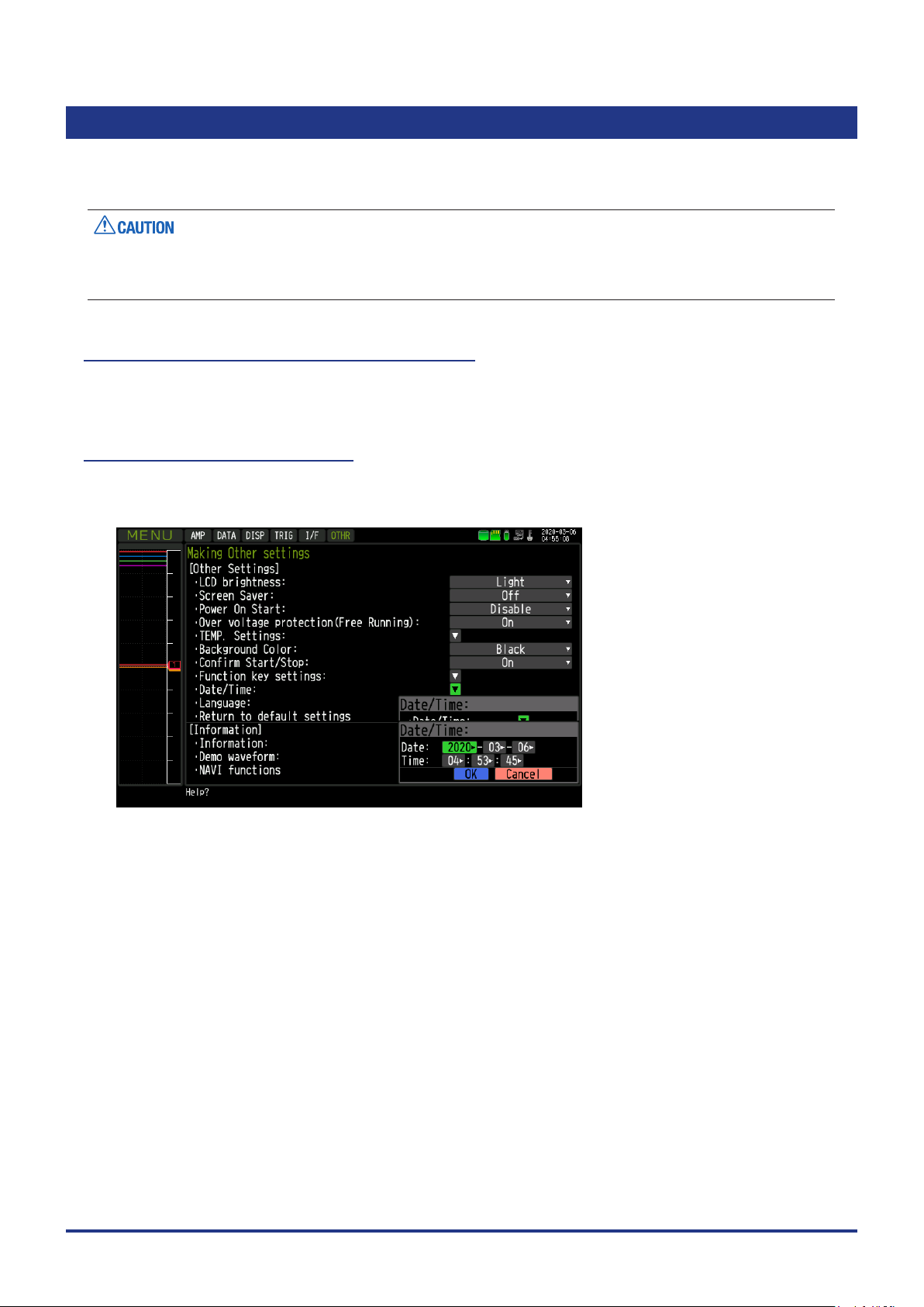
How to Set the Date and Time
Press the [MENU] key, display the “OTHER” screen, and then set the date and time at the Date/Time
Settings sub-menu. For details, refer to “3.4 Setting Menus” - “Date/Time”.
2-28
Page 45

CHAPTER 3 Settings and Measurement
CHAPTER 3 Settings and Measurement
This chapter describes the setting and measurement procedures for this device.
PRODUCT SUMMARY
3.1 Window names and functions
3.2 Key Operation
3.3 Description of the display mode
3.4 Operation Modes
3.5 Setting Menus
3.6 WEB Server Function
3.7 List of Error Codes
3-1
Page 46

CHAPTER 3 Settings and Measurement
3.1 Window names and functions
Y-T Screen
1. Status message
2. TIME/ DIV
3. Status mark
4. Devi ce access display
(Internal memory)
5. Devi ce access display
(SD card)
6. Devi ce access display
(USB memory)
7. Remote lamp
8. Key loc k displ ay
9. Clock display
19. Data c aptur e bar
17. Scale upper limit
18. Y-T Waveform di splay
17. Scale lowe r limit
16. File name disp lay are a
10. AC/Battery status indicator
11. Digital display
12. Quic k sett ings
13. Internal RAM information
14. Alarm d isplay
15. Level bar
3-2
15. Level bar
13. Internal RAM information
Page 47

Logging screen
20. Logging display
CHAPTER 3 Settings and Measurement
21. Statistical calculation
display
14. Alarm indication13. Internal RAM information
3-3
Page 48

CHAPTER 3 Settings and Measurement
XY Screen
27. X-axis level bar
26. / DIV dis play
25. XY waveform displa y
22. Pe n status displ ay
23. XY digita l displ ay
30. Sc ale upp er limi t
29. Position refer ence line
24. Y-axis level bar
28. Vernier reference line
30 Sca le lower limit
3-4
Page 49

CHAPTER 3 Settings and Measurement
1. Status message
Displays the operation status of this device.
: Displayed when data is not being captured.
: Displayed when data is not being captured while XY Screen is used.
: Displayed when the pre-trigger capturing is in progress with the setting to wait for
pre-trigger to complete.
: Displayed while waiting for trigger to initiate after recording has started.
: Displayed when data is captured to the internal RAM.
* : Displayed when data is captured to the internal memory.
* : Displayed when data is captured to the SD card.
* : Displayed when data is captured to the USB memory card.
: Data capturing operation is performed by our application software when connect to
the PC. This status message is displayed when data is not captured to the device.
: Displayed when the device waits for you to press the [START/STOP] key to stop
recording after data capture.
: Displayed when waiting for the repeat interval.
: Displayed when data in the internal RAM is replayed.
* : Displayed when data in the internal memory is replayed.
* : Displayed when data in the SD card is replayed.
* : Displayed when data in the USB memory is replayed.
* : Displayed when replaying during data capture.
* : Displayed when auto save process is in progress.
: Displayed when backup fails (The SD card of the backup destination is removed,
etc.).
: Displayed when demo waveforms are being displayed.
: Displayed while remote lock is released.
* For details of data capture such as trigger and repeat etc., refer to “3.5 Setting Menus” - “(4) TRIG settings”.
* For details of capture settings, refer to “3.5 Setting Menus” - “(2) DATA settings”.
* For details of remote lock release function, refer to User’s Manual GL-Connection.
Please do not turn off the power when the status message states “Capturing to internal memory” or
“Capturing to SD card” (“ * ” status mark).
Start the operation after making sure that the status mark is switched to "STOP".
2. Time/DIV display
With the Y-T Screen, the current time scale is displayed.
Time scale is the current time scale per grid on the horizontal axis.
The display width of the horizontal axis (T-axis) of the waveform is adjustable by changing this value.
3-5
Page 50

CHAPTER 3 Settings and Measurement
3. Status mark
: Appears when neither capture nor replay is in progress.
: Displayed when the captured data is being recorded.
: Appears when waiting for a trigger during capturing and for the stop key after capturing.
: Displayed when replaying the captured data.
: Displayed when replaying during capturing the data (Refer to in “3.2 Key Operation” - “(10)
REVIEW ”.).
Please do not turn Off the power and do not remove the SD card or USB memory when the status mark
indicates other than “STOP”. The data will be damaged, and it will not be accessable.
Please start the operation after making sure that the status mark is switched to "STOP".
4. Device access display (Internal memory)
: Internal memory is recognized but is not being accessed.
: Internal memory is being accessed. While the internal memory is being accessed, the
POWER LED also ashes.
Please do not turn Off this device’s power when accessing the internal memory.
Data will be damaged, and it will not be accessable.
5. Device access display (SD card)
: SD card is not attached.
: SD card is attached but not accessable.
: SD card is being accessed. Do not remove the SD card. The POWER LED light also
ashes during accessing the SD card.
Please do not remove the SD card and do not turn off power when accessing the SD card.
Data will be damaged, and it will not be accessable.
3-6
Page 51

CHAPTER 3 Settings and Measurement
6. Device access display (USB memory)
: USB memory is not attached.
: USB memory is attached but not being accessed.
: USB memory is accessed. Do not remove the USB memory. The POWER LED light also
ashes while the USB memory is being accessed.
Please do not remove the USB memory and do not turn off power when accessing the USB memory.
Data will be damaged, and it will not be accessable.
7. Remote lamp
: Indicates local mode. Operations can be conducted on the device.
: Indicates remote mode. With some exceptions, operations must be conducted on a PC.
When you cancel the connection on the application software, the device automatically
rerturns to local mode. If local mode is not entered, press the [QUIT] key.
8. Key lock display
: Not in key lock status. Normal operations are permitted.
: Key lock status. All keys are locked.
Refer to “(15) Key lock release with password” in “3.2 Key Operation” for details on the key
lock.
9. Clock display
Displays the current date and time.
For details on date and time settings, refer to “3.5 Setting Menus” - “(6) OTHER settings”.
3-7
Page 52

CHAPTER 3 Settings and Measurement
10. AC/ battery status indicator
: Running on AC or DC power supply.
: Running on battery. The remaining battery power is 100 to 91%.
: Running on battery. The remaining battery power is 90 to 61%.
: Running on battery. The remaining battery power is 60 to 31%.
: Running on battery. The remaining battery power is 30 to 11%.
: Running on battery. The remaining battery power is 10% or below.
Data capture automatically stops when the remaining battery power drops to 10% or below during.
•
Auto Save will be performed even when Auto Save is not set while data is being captured to the internal
RAM.
The power is automatically turned off when the remaining battery power is 0%.
•
Use the remaining battery display only as a reference.
•
This indicator does not guarantee the exact operating time of a battery.
11. Digital display of Y-T screen
Displays the input value of each channel and span. Use the [SPAN/TRACE/POSITION] keys to switch the
display.
Use the keys to select the channel you want to activate (enlarged display).
The waveform of the active channel is displayed at the top.
: Displays the input value.
: The span of the active channel can be changed using the keys.
: The position of the active channel can be changed using the keys.
: The ON or OFF of the active channel display can be changed using the keys.
For details, refer to “3.2 Key Operation” - “(2) SPAN/TRACE/POSITION”.
As described below, the CH indicating the calculation mark is the channel which calculation between the
CHs is enabled (On).
Calculation mark
12. Quick settings
The settings of the sampling interval and the division of waveform display can be changed. Use the keys
to activate the Quick setting and the left/right keys to change values.
* The "SAMPLE" item cannot be changed during data capture.
3-8
Page 53

CHAPTER 3 Settings and Measurement
13. Internal RAM information
Displays the status of the internal RAM. The status of the block can be judged by the color of each block.
For the number of blocks, set the division number by "memory block division".
: Data was not captured. It is an empty block.
: Pre-trigger data is being captured.
: Data is being captured.
: Data capture is completed but auto save is not performed.
: Data capture is completed. Auto save has been performed.
: Auto save is performed. The auto save progress is indicated by a dark green bar.
: The yellow line at the top of the block indicates that this device is capturing.
: The yellow line at the top of the block indicates the block scheduled to be captured next
time.
14. Alarm display
Displays the alarm output status.
The number with which an alarm went off is displayed in red. The channel with the alarm threshold has a red
input value in the digital display area.
15. Level bar
Displays the channel signal position, trigger position and alarm range.
Trigger position Alarm range
Rising Falling Win In Wi n Out
Stop position
Start position
3-9
Page 54

CHAPTER 3 Settings and Measurement
16. File name display
(1) During data capture
A le name is displayed during the recording.
* If the ring capturing setting is ON, a le name displayed during capture ends with "_RINGx" (x
represents a number) but the actual le name does not include "_RINGx".
As an example, if the ring capturing is set to ON in the above gure, the le name during recording will
be displayed, as "<MEM>170711\PREFIX_170711-130955_RING4.GBD" but the actually le created will
be "<MEM>170711\ PREFIX_170711-13 0 955.GBD".
* For details, refer to “3.5 Setting Menus” - “(2) DATA settings”.
(2) During data replay
Information on the time axis of the cursor is displayed during Y-T replay.
Time to wh ich the c ursor points
Selected cursor
Time differ ence b etwe en Cursors A and B
17. Scale upper/lower limit
Displays the scale upper/lower limit of the currently active CH.
18. Y-T waveform display
Displays the Y-T waveform of the input signal.
(The vertical axis is the measured value and the horizontal axis is time.)
3-10
Page 55

CHAPTER 3 Settings and Measurement
19. Capture bar
(1) During recording
Displays the elapsed time and the usage status on the internal memory, the SD card and the USB
memory usage.
Elapsed time Remai ning tim e for dat a capture
Used capacity of internal m emor y, SD
card an d USB me mory
Total capacity o f internal mem ory, SD card and U SB mem ory
Remai ning capacit y of inte rnal me mory, SD
card an d USB me mory
For example, when you are using a 4GB SD card with 100MB already used, the total capacity of the SD
card is 4GB with 100MB used space, and the available space of the SD card would be approximately
3.9GB. As the captured time elapses, the usage of the SD card increases and the remaining capacity of
the SD card decreases.
The remaining recording time indicates the remaining capacity of the SD card.
However, when the relay capturing function is set to Off, and when the remaining capacity of the SD card
exceeds 4GB, the remaining time that can be captured to 1 le will indicate 4GB.
* Remaining time which is more than 99999 hours is displayed as "++++:++:++".
(2) During data replay
Show the display position, cursor position, and trigger position graphically.
Cursor A position Cursor B position
Capture data s ize
Range for which a waveform is currently
displayed
3 -11
Page 56

CHAPTER 3 Settings and Measurement
20. Logging display
Displays the digital value of the input signal in large character.
The window can be divided into 2, 4 or 8 displays. Select from choices of analog CH, logic, or pulse CH.
2-divided 4-divided 8-divided
21. Real time statistical calculations display
Displays the real time statistical calculation result (simultaneous display for 4 different calculations).
Maximum value P-P value
Real ti me value Minimum value Average value
3-12
Page 57

22. Pen status display
Displays the UP/DOWN status of the pen in the XY screen.
When pen is UP st atus
CHAPTER 3 Settings and Measurement
The current pe n posit ion is
drawn wi th a yellow dot.
When pen is DOWN status
When recording starts, the display automatically puts the pen on DOWN status.
The tra jectory of th e pen is
drawn wi th colo r used wi th
XY- CH .
3-13
Page 58

CHAPTER 3 Settings and Measurement
23. XY screen digital display
Displays the input value of CH set to XY-axis, /DIV display, Position, Vernier. To switch the screen use the
[SPAN/TRACE/POSITION] key.
L-R key mode:
Select the XY-CH and the axis to be activated (enlarged display) with the
addition, the waveform display of active XY-CH is shown at the top of the screen.
Change the settings of the selected axis of the selected active XY-CH with the keys.
Cross key mode:
Select XY-CH to be active (enlarged display) with the [CH SELECT] key. In addition, for active XY-CH, the
waveform is shown at the top of the screen.
For the selected active XY-CH, change the settings of the X-axis with the keys, and the Y-axis with the
keys.
: Displays the input value.
: Changes the Range/Span of active XY-CH.
: Changes the Position of active XY-CH.
: Changes the Vernier of active XY-CH.
keys or [CH SELECT] key. In
The settings of Range/Span, Position and Vernier belong to each analog CH.
•
When the same analog CH is assigned to another XY-CH, changing the setting of one XY-CH changes all
•
the XY-CH settings at the same time.
For details, refer to “3.2 Key Operation“ - “(2) SPAN/TRACE/POSITION” and “3.3 Operation Modes” - “(3) XY
waveform display” - “XY digital display”.
In XY-CH display, the contents of the X-axis (horizontal axis) are shown on the upper row and the contents
of the Y-axis (vertical axis) are at the lower row.
Conte nts of X-a xis
Conte nts of Y-axis
3-14
Page 59

CHAPTER 3 Settings and Measurement
24. Y-axis level bar
Displays the signal position of CH set on the Y-axis.
In the Y-axis level bar, the trigger range and the alarm range are not visable.
25. XY waveform display
Displays XY waveform graph.
Set any analog CH to X-axis (horizontal axis) and Y-axis (vertical axis) respectively.
26. DIV display
Displays the measurement amount (unit) for one grid in XY waveform graph.
27. X-axis level bar
Displays the signal position of CH set on the X-axis.
In the X-axis level bar, trigger ranges and alarm ranges are not visable.
28. Vernier reference line
Displays the Vernier reference line when POSITION setting and the Vernier setting are visable on the XY
digital screen or when "Origin" is selected by the Quick setting (a green straight line).
When the Vernier is set to 100%, Vernier reference line is visable at 5DIV position.
When the Vernier setting is changed, Vernier reference line moves according to the percentage (%) of
Vernier.
For example, when the Vernier is set to 80%, the Vernier reference line moves to 4DIV position.
For details of Vernier function, refer to "3.3 Operation Modes" - "(3) XY waveform display" - "Vernier".
3-15
Page 60

CHAPTER 3 Settings and Measurement
29. XY position reference line
Displays when the Position settings and the Vernier settings are visable in the XY digital screen or when
"Origin" is selected by the Quick setting (It is a pink straight line).
In the Range mode, the reference value is 0V (0Vrms).
In the Span mode, the reference value is the center position of the span.
The XY position reference line indicates the display position of the reference value.
For the XY position, the reference position can be set to the left (lower) of the XY graph as 0% and the right
(upper) as 100%. (Be cautious of the difference from the Y-T graph position setting.)
For details of the XY position function, refer to "3.3 Operation Modes" - "(3) XY waveform display" - " XY
position".
30. XY upper/lower scale
Show the XY upper/lower scale when the Position setting and the Vernier setting are displayed in the XY
digital screen.
The measured values of the left and right edges (X-axis) and the upper and lower edges (Y-axis) of the XY
graph are displayed.
3-16
Page 61

3.2 Key Operation
This section describes key operation.
(1) CH SELECT (2) SPAN/TRACE/POSITION
CHAPTER 3 Settings and Measurement
(3) TIME/ DIV
(5) QUI T
(13) FI LE
(14) F UNC
(12) CURSOR (ALARM CLEAR)
(1) CH SELECT
(4) MENU
(6) DIRE CTIO N Keys
(7) ENTER
(8) FAST FORWAR D (KEY LO CK)
(9) START/S TOP (US B DRIVE)
(11) DI SPL AY
(10) REV IEW
Moves CH and item in digital display.
Use keys on the CH SELECT buttons to move the logging screen and real
time statistics calculation screen up and down.
Y-T waveform screen
XY waveform scr een
Move down w ith the
key
Move down w ith the
key
Move up wit h the
key
Move up wit h the
key
3-17
Page 62

CHAPTER 3 Settings and Measurement
(2) SPAN/TRACE/POSITION
Switch to change the information on the digital display.
Use to change the settings related to waveform display during Free Running,
data capture and data replay.
Pressing the key will switch displays as follows:
Y-T sc re en
MONITOR SPAN POSITION TRACE
Displays digital values
(default status)
Use [CH SELECT] key or
Allows ch anging of t he
span value
keys to move the CH.
Allows ch anging of t he
position
Allows tur ning ON /
OFF of the w aveform
display
* Data is c apture d even
if OFF is se t.
Change the contents of the selected CH with keys.
* When set at ALL, setting values for CH1 is reected on other channels.
When CH1 is OFF, setting for ALL is disabled.
* When Logic CH is selected, use keys to select individual CH for
Logic.
XY scr een
MONITOR RANGE/SPAN POSITION VERNIER
3-18
Displa ys the digit al
value. (Default
status)
Allows changing of the
range/span value
(waveform
amplitude).
Allows changing of the
position (center
positi on of wavefo rm).
Allows changing of the
vernie r (ne
adjustment of
waveform amplitude).
· L-R key mode
Use [CH SELECT] key or keys to move XY-CH and axis.
Use keys to change the contents of the selected XY-CH and axis.
· Cross key mode
Use [CH SELECT] key to move XY-CH.
Use the keys to change the contents of the X-axis, and use keys to
change the contents of the Y-axis.
(In the Quick setting area, use keys to change the contents.)
Page 63

(3) TIME/DIV
(4) MENU
CHAPTER 3 Settings and Measurement
Press the [TIME/DIV] key to change the time axis display width.
TIME/DIV display
Open the settings window to capture data. For details on settings, refer to “3.5
Setting Menus”.
(5) QUIT ( LOCAL)
* For details of remote lock release function, refer to GL-Connection User’s Manual.
This key is primarily used for the following operations.
• To cancel a setting during menu conguration.
• To return to the MONITOR screen when the SPAN/TRACE/POSITION screen
is displayed.
• To cancel remote status (When the keys are disabled) through interface
control.
• To close the menu screen.
• To quit data replay.
• To stop drawing the XY replay waveform.
• To clear the Real time statistical calculation. (during free running mode)
3-19
Page 64

CHAPTER 3 Settings and Measurement
(6) Direction Keys
This key is primarily used for the following operations.
• To move a menu or setting item during menu conguration.
• To move the cursor during replay.
• To move the active channel in the “Digital display” and “Logging screen” (
keys).
• To change the setting of SPAN/TRACE/POSITION ( keys).
• To change the Quick setting ( keys).
• To change the channel to be displayed on the “Logging screen” ( keys).
(7) ENTER
This key is primarily used for the following operations.
• To nalize setting items during menu conguration or open submenus.
(8) FAST FORWARD key (KEY LOCK)
This key is primarily used for the following operations.
• To move the cursor at high speed during replay.
• To change the display order of the les in the le selection tool.
• To set key lock (Hold down the left/right FAST FORWARD key for at least two
seconds. Press again to unlock)
A password for canceling the key lock can be specied.
For details, refer to “3.2 Key Operation” - “(15) Key lock release with
password”.
• To change the display mode in the “Logging display” and “Real time statistical
calculation display”.
2-division 4-division 8-division
• Select individual logic CH with Logic CH in Y-T digital display.
Real time statistical
calculation
3-20
Page 65

CHAPTER 3 Settings and Measurement
(9) START/STOP (USB Drive Mode)
This key performs the following two operations:
<Starts/stops capture>
• During Free Running, starts capture.
• During capture, stops capture.
USB Drive Mode
In the “USB Drive Mode”, check the internal memory and SD card as external storage devices on the PC.
They will be recognized as two external storage media.
Transfer and delete les since two external storage media are recognized as a removable disk.
1. Using a USB cable, connect to the PC.
2. To enter the USB Drive Mode, press down [START/STOP] key from when the power is turned on until the
display below appears.
3. The external storage media is recognized by the PC and data exchange becomes possible.
* In USB Drive Mode, the display on this device becomes as follows:
To exit USB Drive Mode, turn off and turn on the power again.
•
During USB Drive Mode, no operation including data capture and data replay is available.
•
USB memory does not conform to USB Drive Mode.
•
3-21
Page 66

CHAPTER 3 Settings and Measurement
(10) REVIEW
This key is used to replay captured data.
• During Free Running, captured data is replayed.
Display the "Data Replay Source" screen, and then set the internal RAM data
or le you want to replay.
• While capturing data, real-time recorded data is replayed.
<Replaying display during data capture>
To exit the replay display, press the [QUIT] key.
For CSV-formatted data, only the data captured by this device can be displayed.
Also, when the data recorded in CSV format is replayed, the unit of the temperature data is displayed in “deg
C” rather than “°C” format.
3-22
Page 67

11) D I SPL AY
The key is used to switch the screen mode.
When running Free Running (when the capturing is stopped) mode, the screen
mode can be switched between data capturing and data replaying.
Pressing this key switches the screen display as follows:
<When Free Running and data capturing>
CHAPTER 3 Settings and Measurement
<Waveform + Digital display>
Displays the Y-T waveform and the Digital display.
Settings can be changed using the [SPAN/TRACE/POSITION]
key.
<All waveform screen>
Displays only the waveform in full screen mode.
<Logging display + Real time statistical calculation screen>
Logging display and Real time statistical calculation screen in
letters.
Use the
mode. The calculation results are displayed only when switched
to "Real time statistical calculation screen".
Refer to “3.2 Key Operation” - “(8) FAST FORWARD key (KEY
LOCK)” for details on ”Real time statistical calculation screen”.
<XY screen>
Displays XY waveform and XY digital display.
In addition, You can change the settings" using SPAN/TRACE/
POSITION" key.
FAST FORWARD keys to change the display
3-23
Page 68

CHAPTER 3 Settings and Measurement
(12) CURSOR (ALARM CLEAR)
• This key is used to switch between cursor A and B during replay.
Pressing this key switches between cursor A and B.
For details on cursor operation, refer to “3.5 Setting Menus” - “(8) Data replay
menu”.
Cursor A Cursor B
• When the alarm setting is “Hold generated Alarm”, the alarm on hold is
cleared.
Cursor B Cursor A
(13) FILE
Alarm-generated channels
Alarm output terminal status
• Black : Alarm is no t issue d
• Red : Ala rm is issued
This key is used to execute le-related operations.
• Performs the operations (copy, delete, and transfer, etc.) for the internal
memory, SD card and USB memory.
• Execute the screen copy
• Saves all data or data between cursor A and cursor B during replay (set during
replay only)
• Saves the data in the internal RAM to a le.
• Saves or reads the current set conditions. (can be set during Free Running
only).
• Replaces the SD card or USB memory during data capture (Can be set when
data is being backed up.).
For details on the le operation, refer to “3.5 Setting Menus” - “(7) FILE menu”.
3-24
Page 69

(14) FUNC
CHAPTER 3 Settings and Measurement
Execute the function operation.
Take a shortcut with the key by selecting the frequently used function in
advance. In addition, selection can be made anytime.
For details of function operation, refer to "3.5 Setting Menus" - "(6) OTHER
settings" - "FUNC key settings".
Shortcut execution mode: The set operation is executed immediately (shortcut
execution).
Selection execution mode: Select the operation you want to execute and then
execute it.
Using th e keys, select the
execut ion content th at you can s elec t
and the n pres s the ENTER key to
execute it.
3-25
Page 70

CHAPTER 3 Settings and Measurement
(15) Key lock release with password
A password can be set to cancel the key lock.
(No password is set at factory default.)
<Operation ow>
1. Set the password.
Press the , , and [ENTER] keys at the same time to display the password setting screen shown below.
Specify a 4 digit password.
Use the
Specifying 0000 will disable password operation.
In case you forgot your password, please contact us for the master password.
2. Set the password.
Hold down the and keys together for at least two seconds.
3. Cancel the key lock.
Hold down the and keys together again for at least two seconds.
The password setting screen shown below will be displayed. Set a password.
Entering an incorrect password will not cancel the key lock.
Key lock state will be retained when power is turned off.
,
, , keys to select numbers. Press the [ENTER] key to conrm the password.
3-26
Page 71

CHAPTER 3 Settings and Measurement
3.3 Description of the display mode
(1) Y-T waveform display
The Y-T waveform is a graph in which the vertical axis is measured value (Y) and the horizontal axis is time
(T).
The horizontal axis (T) can be adjusted by Time/DIV setting. Adjust the display width of the horizontal axis (T)
of the waveform by changing this value.
With the vertical axis (Y), display position and display width can be adjusted by range setting, span setting
(position setting) and zone setting.
The graph waveform can be turned On/Off by trace setting. Even when trace (display) is off, the data can be
saved in the internal RAM, internal memory, SD card, USB memory.
Display format
The Y-T waveform display screen has two display formats.
Waveform + Digital display
•
Digital display
Y-T graph wavef orm
Using Y-T graph waveform on the left side and digital value on the right side, currently measured values
can be monitored.
Full waveform screen
•
Y-T graph wavef orm
With this display format, you can display the time axis of Y-T graph waveform can be views wider by
hiding the digital display.
3-27
Page 72

CHAPTER 3 Settings and Measurement
Zone division
Zone division is a function to divide the Y-axis of the Y-T graph into multiple zones and display them so that
the graphs do not overlap.
Select from 1-zone (no zone division), 2-zone division, 4-zone division or 8-zone division.
* For 4-zone division and 8-zone division, 4DIV above and below the center is used for display.
Analog CH and pulse CH can be freely allocated to each zone.
1
1-zone (no zone division)
1
2
2-zone division
1
2
3
4
4-zone division
1
2
3
4
5
6
7
8
8-zone division
3-28
Page 73

CHAPTER 3 Settings and Measurement
For Logic CH, 10 zones are provided in advance, so you can select the zone to display the Logic CH
waveform.
1
2
3
4
5
6
7
8
9
10
10-zone division
•••••
Zone 1 Zone 2 Zone 3 Zone 10
•••••
3-29
Page 74

CHAPTER 3 Settings and Measurement
Active CH (priority display CH)
Active CH is a CH that displays over the other CHs.
The CH selected in the digital display is the active CH.
The active CH is displayed above the other CH, giving you easier view of the individual channel.
CH1 is act ive CH.
Since t he waveform of CH 2 is hidden
under t he wavef orm of CH1, it c annot b e
visually recognized.
CH2 is ac tive CH .
The waveform of CH 2 is disp layed on t he
top, so you c an visually re cognized it.
Time/DIV
Time/DIV is a function that you can enlarge or shrink the horizontal axis (T) of the Y-T graph waveform.
Set the time with one grid of graph.
The shorter the set time, the larger the horizontal axis (T).
Time/DIV display
Set time with one grid of graph.
Enlarge
Shrink
200ms/DIV 100m s/ DIV
Use DISP menu and [TIME/DIV] key to set Time/DIV.
3-30
Page 75

CHAPTER 3 Settings and Measurement
Span
Span is a function to set measurement value of the upper and lower edges in the zone.
By using the span setting, you can enlarge or shrink the vertical axis (Y) of the Y-T graph waveform.
Upper edge
Span value
Lower e dge
The span value is displayed as the scale display of the CH set to the active CH.
Span value can be changed in the AMP menu. You can perform simple Settings from the digital display.
In the Span setting, use the keys to change the amplitude of the span.
Smaller the amplitude value, wider the graph waveform displayed.
In Position setting, use the keys to move the span in parallel.
3-31
Page 76

CHAPTER 3 Settings and Measurement
Digital display
The digital display is seen on the right side in the "Waveform + Digital display".
Digital display
The digital display has the following functions.
· See the measured value with a digital value.
· Show CH where the alarm occurred.
· Sets active CH.
· Performs simple setting of SPAN, POSITION and TRACE.
· Operates Quick setting.
Active C H
Quick s etti ng
The CH where the input is set to Off does not display on the waveform.
3-32
Page 77

Digital display of measured value
<Analog CH/Pulse CH>
During Free running/capturing
CH number
Calculation mark
CH annotation
Measured value
Active C H
CH number
CHAPTER 3 Settings and Measurement
Inactive CH
Measured value
CH number : Measured CH number.
Calculation mark : Displayed when calculation between channels is set.
CH annotation : An annotation set to CH is displayed. When the number of annotation characters is
larger than the display area, all the character strings are displayed by scrolling to the
left.
Measured value : Current measured value (instantaneous value) is displayed.
When an alarm triggers the measured values are highlighted in red
During replaying
Cursor A m easured value
Cursor B m easured value
Diff eren ce value b etwe en
Active C H
cursor s A and B
Sele cted c ursor m easur ed
Inactive CH
value
Cursor A measured value : The measured value of the data pointed where cursor A is located is displayed.
Cursor B measured Value : The measured value of the data pointed where cursor B is located is displayed.
Difference value between
cursors A and B : The difference of measured values between cursor A and B is displayed.
When cursor A is selected, value from B value to A is displayed, and when
cursor B is selected, value from A value to B value is displayed.
Selected cursor
measured value : The measured value of the data pointed to the current selected cursor is
displayed.
3-33
Page 78

CHAPTER 3 Settings and Measurement
<Logic CH>
• During Free running/capturing
Logic selection cursor
Logic annotation
CH number
Active C H
CH number
Inactive CH
Measured value
Measured value
CH number : Logic CH number
Logic annotation : Annotation of the logic CH selected by the logic selection cursor is displayed.
Logic selection cursor : Select individual logic CH. Use and keys to move on the logic CH.
Measured value : The measured value of the logic CH is displayed.
: High level
: Low level
• During replay
Cursor A m easured value
Cursor B m easured value
Active C H
Sele cted c ursor m easur ed valu e
Inactive CH
Cursor A measured value : The measured value of the data pointed by cursor A is displayed.
Cursor B measured Value : The measured value of the data pointed by cursor B is displayed.
Selected cursor measured value : The measured value of the data pointed to the current selected cursor is
displayed.
3-34
Page 79

Set active CH
Switch between the active CH by operating the [CH SELECT] key or the
key
key
CH2 is ac tive.CH1 is act ive.
Simple setting of SPAN /POSITION/TRACE
Choose each setting by pressing the [SPAN/TRACE/POSITION] key.
Y-T sc re en
MONITOR SPAN POSITION TRACE
CHAPTER 3 Settings and Measurement
keys.
Displays digital values
(default status)
Allows ch anging of t he
span value
Allows ch anging of t he
position
Allows tur ning ON /
OFF of the w aveform
display
* Data is c apture d even
if OFF is se t.
Use [CH SELECT] key or the keys to move on the CH.
Change the contents of the CH selected with the key.
* When ALL is set, setting values for CH1 is reected on other channels.
When CH1 is OFF, ALL cannot be set.
* When Logic CH is selected in "MONITOR" or "TRACE", use and keys
to select individual CH of logic.
3-35
Page 80

CHAPTER 3 Settings and Measurement
Quick setting
Quick setting is a function that you can perform the settings in the digital display without opening the setting
menu.
• Sampling interval (SAMPLE)
You can change the sampling interval setting.
Use the keys to change it. However, you can only change it only while Free running is executed. You
cannot change it during capturing. The sampling interval is not displayed during replaying.
When changing the sampling interval, the Time/DIV value may be changed depending on the limitation.
• Zone division (ZONE)
The number of zone divisions can be changed.
Use the keys to change setting. When changing the number of zone divisions, setting of CH
allocated to the zone is displayed.
You can change the number of zone divisions at any time.
• Search (SEARCH)
Performs waveform search according to the level search conditions set in the Data Replay menu during
replaying.
Use key to search the past data and use the key to search future data from the current set point.
Before using this function, set the search level from the Data Replay menu.
3-36
Page 81

CHAPTER 3 Settings and Measurement
(2) Logging display/real time statistical calculation display
The logging display is a function to digitally display the current measured value with large fonts on the
display screen.
Visibility is improved by use of large fonts.
Real time statistical calculation display is a function to calculate and display maximum value, minimum value,
P-P value, and average value. Use DISP menu, [FUNC] key function and [QUIT] key to clear the statistical
calculation during Free running.
Additionally, the statistical calculation is cleared when capturing is started.
To switch between display modes, press the and keys.
2-division 4-division 8-division
Real time statistical
calculation
Besides the real time statistical calculation display, the following key operations are possible.
Use [CH SELECT] key or the keys to move on the selected section.
key
key
Use the
keys to change the CH displayed on the selected section.
3-37
Page 82

CHAPTER 3 Settings and Measurement
Logging display
CH number
Calculation mark
CH annotation
Measured value
CH number : Measured CH number.
Calculation mark : Displayed when calculation between channels is set.
CH annotation : Annotation set to CH is displayed.
Measured value : Currently measured value is displayed.
Level indication : Level position of measured value is displayed with a pointer.
Level display
Real time statistical calculation display
Analo g CH only Analo g CH + Logic CH Analog CH + Pulse CH
CH number
Calculation mark
CH annotation
Measured value Max. value Min. value P-P value Average value
CH number : Measured CH number.
Calculation mark : Displayed when calculation between channels is set.
CH annotation : Annotation set in CH is displayed.
Measured value : Currently measured value is displayed.
<Statistical calculation value>
Use DISP menu, [FUNC] key and [QUIT] key to clear the statistical calculation during Free running.
Also, the statistical calculation is cleared when the capturing is started.
Maximum value : Maximum value after clearing
Minimum value : Minimum value after clearing
P-P value : A value between the maximum value and minimum value.
Average value : Average value after clearing
3-38
Page 83

CHAPTER 3 Settings and Measurement
(3) XY waveform display
XY waveform display is a function to show a graph with measured values for both the horizontal X-axis and
the vertical Y-axis.
Since the graph is drawn based on measured values of CH set on the horizontal axis and vertical axis, it
allows to check the correlation between both data graphically.
XY waveform display mode has RANGE mode, SPAN mode, POSITION dedicated to XY and VERNIER
functions.
Setting operation is much like the operation of the XY pen recorder
Digital display
XY graph wavefo rm
RANGE mode/SPAN mode
This device has RANGE and SPAN mode.
RANGE mode: Switches to the optimum range (amplier sensitivity) in conjunction with the FS (full scale)
range set in the AMP menu.
SPAN mode: Sets the span width when using temperature and humidity, EU function, calculation between
CHs function.
Refer to the following table to see which mode is set in various settings.
Input EU
Voltage Off Off Range
On Off Span
Off On Span
On On Span
Root mean square value
Temperature
Humidity
Off Off Range
On Off Span
Off On Span
On On Span
- -
- -
The mode that is operating currently is displayed on the digital screen.
Calculation between
CHs
Mode
Span
Span
: RANGE mode
: SPAN mode
3-39
Page 84

CHAPTER 3 Settings and Measurement
The differences in XY digital display operation are as follows.
Mode RANGE/SPAN POSITION VERNIER
RANGE Use the keys to change
SPA N Use the keys to change
the V/DIV range.
The V/DIV range cannot be
changed during replay.
the Span width.
The Span width cannot be
changed during replay.
Position reference point is 0V
or 0Vrms.
Position reference point is the
center point of the span.
100 to 50% (40%)
100 to 40%
In RANGE mode, the relationship between the FS range displayed by the AMP setting and the V/DIV range
displayed on the XY digital display are as follows. In addition, the VERNIER setting range in each range is
as shown in the following table.
FS range V/DIV range
20mV 1mV/DIV 100% to 50%
50 mV 2mV/ DIV 100% to 40%
100 mV 5mV/DIV 100% to 50%
20 0mV 10 mV/DIV 100% to 50%
50 0mV 2 0mV/DIV 100% to 40%
1V 50mV/ DIV 100% to 50%
2V 100mV/DIV 100% to 50%
5V 200mV/DIV 100% to 40%
10V 500mV/DIV 100% to 50%
20V 1V/D IV 100% to 50%
50V 2V/DIV 100% to 40%
100V 5V/DIV 100% to 50%
200V 10V/DIV 100% to 50%
500V 20V/ DIV 100% to 40%
Vernier setting
range
FS range V/DIV range
10mVrms 0.5mVrms/ DIV 100% to 50%
25mVrms 1mVrms / DI V 100% to 40%
50 mVrms 2.5mVrms/DIV 100% to 50%
100 mVr ms 5mVrms/DIV 100% to 50%
250mVrms 10mVrm s/D IV 100% to 40%
50 0mVrms 25 mVrms /DIV 100% to 50%
1Vrms 5 0mVrms/DIV 100% to 50%
2.5Vrms 100mVrms/DIV 100% to 40%
5Vrms 250mVr ms/ DI V 100% to 50%
10Vrms 500mVrms/DIV 100% to 50%
25Vrms 1Vrm s / DIV 100% to 40%
50Vrms 2.5Vrms/DIV 100% to 50%
100Vrms 5Vrms/DIV 100% to 50%
250Vrms 10Vrms/DIV 100% to 40%
Vernier setting
range
Since the RANGE affects the hardware operation (amplier sensitivity), it cannot be altered during capturing
or replaying.
The RANGE setting is common to the RANGE setting of the Y-T graph.
The display amplitude of the waveform is determined by the range and X-Y dedicated position, and Vernier
settings, without span setting of Y-T graph.
In SPAN mode, the SPAN can be changed within the same range as the Y-T graph.
Set the SPAN in RANGE/SPAN display of XY digital display with ease. In addition, details can adjusted using
the AMP menu setting or DISP menu setting.
It is common to use span setting of Y-T graph.
3-40
Page 85

CHAPTER 3 Settings and Measurement
XY position
In the position function of XY graph display (hereinafter XY position), set the drawing position reference point
to 0% for the lower left corner and 100% for the upper right corner of the XY graph.
100%
50%
0%
0% 50% 100%
The measurement range displayed on the graph by the XY position setting is as follows.
-10D IV - 5DIV Reference point 5DIV 10DIV
Position 100%
Position 70%
Position 50%
Position 10%
Position 0%
As shown in the above gure, the display range moves in parallel with 10DIV area with the XY position
setting.
XY position setting is used for XY graph setting only.
Position reference point differs between RANGE mode and SPAN mode.
• RANGE mode
The position reference point in RANGE mode is 0V or 0Vrms.
-FS Reference point
+FS
0V, 0Vrms
• SPAN mode
The position reference point in SPAN mode is the center point between the upper limit span value and
the lower limit span value.
SPAN mo de
Lower lim it span va lue
Reference point
Center p oint of the upper an d lower limit span
= (upper limit span va lue + lower limit sp an value) / 2
Upper limit spa n value
3-41
Page 86

CHAPTER 3 Settings and Measurement
When setting the XY position, a position reference line (pink line) indicating the position reference value is
displayed.
XY position setting
Position reference line
VERNIER
The VERNIER is a function to adjust the amplitude (gain).
Adjust the display width range of the waveform displayed on the XY graph.
-10D IV -5DIV
Reference point 5DIV 10DIV
Position 100%
Position 80%
Position 60%
Position 50%
Position 40%
10DIV
When the VERNIER is set to 100%, it becomes an equal magnication. Therefore the waveform display is
shrunk by the VERNIER setting magnication.
For example, when the VERNIER is set to 80%, it is displayed with a size of 80% compared with 100%.
(The above gure shows the sample when the XY position is set to 50%)
During VERNIER setting, a VERNIER reference line (green line) pointing to the VERNIER magnication is
displayed.
VERNIER setting
VERNIER reference line
The VERNIER reference line is displayed at the position of 5DIV from the position reference point when the
VERNIER is set to 100%. When the VERNIER is set to 80%, it is displayed at the position of 4DIV from the
position reference line (80% position compared with 100%).
3-42
Page 87

XY digital display
XY digital display
The XY digital display has the following functions.
· Displays the measured value as a digital value.
· Active XY-CH setting.
· RANGE/SPAN/POSITION/VERNIER setting.
· Quick setting
XY digital display
CHAPTER 3 Settings and Measurement
Quick s etti ng
XY-CH which TRACE is set to Off is not displayed.
3-43
Page 88

CHAPTER 3 Settings and Measurement
Digital display of measured value
• During Free running/Capturing
XY-CH number
X-axis CH number
X-axis CH annotation
RANGE/SPAN mode
RANGE/SPAN mode
display
display
X-axis measured value
Y-axis me asure d value
Y-axis CH annotationY-axis CH number
Act iv e XY-C H
XY-CH number
X-axis measured value
Y-axis me asure d value
Inactive XY-CH
XY-CH number : XY-CH number.
RANGE/SPAN mode display : Displays the selected CH operating in RANGE mode or SPAN mode.
X(Y)-axis CH number : Analog CH number set on the X(Y)-axis.
X(Y)-axis CH annotation : Annotation of the analog CH set on the X(Y)-axis is displayed. When
the number of annotation characters is larger than the display area, all
the character strings are displayed by scrolling to the left.
X(Y)-axis measured value : Current measured value (instantaneous value) is displayed.
3-44
Page 89

• During replays
CHAPTER 3 Settings and Measurement
XY-CH number
X-axis CH number
X-axis CH annotation
RANGE/SPAN mode
display
RANGE/SPAN mode
display
Y-axis CH number
Y-axis CH annotation
Act iv e XY-C H
XY-CH number
Value indicated by
selected cursor on X-axis
Value indicated by
selected cursor on Y-a xis
Inactive XY-CH
XY-CH number : XY-CH number
RANGE/SPAN mode display : Displays which CH is operating in the RANGE mode or the SPAN mode.
X(Y)-axis CH number : Analog CH number set to the X(Y)-axis.
X(Y)-axis CH annotation : Annotation of the analog CH set to the X(Y)-axis is displayed. When the
number of annotation characters is larger than the display area, all the
character strings are displayed by scrolling to the left.
X(Y)-axis cursor A (B) indication
value :
The indication value on the graph designated by each cursor is displayed.
Value differences between cursor A and B on X(Y)-axis
: Displays the difference of measured values between cursors A and B.
When cursor A is selected, B-A value is displayed. When cursor B is
selected, A-B value is displayed.
Value indicating by selected cursor : The indication value on the graph designated by the current selected
cursor is displayed.
3-45
Page 90

CHAPTER 3 Settings and Measurement
L-R key mode and Cross key mode
XY digital display has 2 operation modes.
2 operation modes are L-R key mode with the same key operation as the Y-T waveform screen and Cross
key mode optimized for operation of XY waveform screen.
• L-R key mode
Move XY-CH and axis with the [CH SELECT] key (hereafter CS key) or the keys.
Change the contents of XY-CH and axis selected with the keys.
While in "MONITOR" display, you can move the XY-CH with the CS key or the keys during Free
running or capturing. (This does not apply during replaying even in "MONITOR" display.)
Use the C S key or t he
key to move do wn.
Use the C S
key to move up .
key or the
Move XY- CH
In addition to the above setting, use CS key or the keys move the axis. Then, press the same
direction key to move between XY-CH channels.
* The contents sandwiched between and marks the active XY-CH.
Use the C S key or
key to move
the
down.
Use the C S
key to move up .
key or the
Move axi s M ove XY- CH
Use the C S
the
down.
Use the C S
the
Change the setting contents of XY-CH/axis selected with the
key or
key to move
key or
key to move up .
keys.
3-46
and keys
Page 91

CHAPTER 3 Settings and Measurement
In the "MONITOR" display during replaying, the cursor moves on the selected axis. Move to decreases move
/left (down) with the key, and to increases move /right (up) with the key.
Sele ct X-a xis
key key
key
key
Se le ct-Y a xi s
• Cross key mode
Move XY-CH with [CH SELECT] key (hereafter CS key).
Use the keys to change the contents of the X-axis, and use the keys to change the contents of
the Y-axis.
(In Quick setting area, use the key to change contents.)
Use CS key to move XY-CH.
Use the C S key or t he
key to move do wn.
Use the C S
the
key or
key to move up .
Use the C S
key to move do wn.
Use the C S
the
key or the
key or
key to move up .
Move XY- CH
Change the setting contents of X-axis for XY-CH selected with the keys.
The keys
Change the setting contents of Y-axis for XY-CH selected with the keys.
The keys
3- 47
Page 92
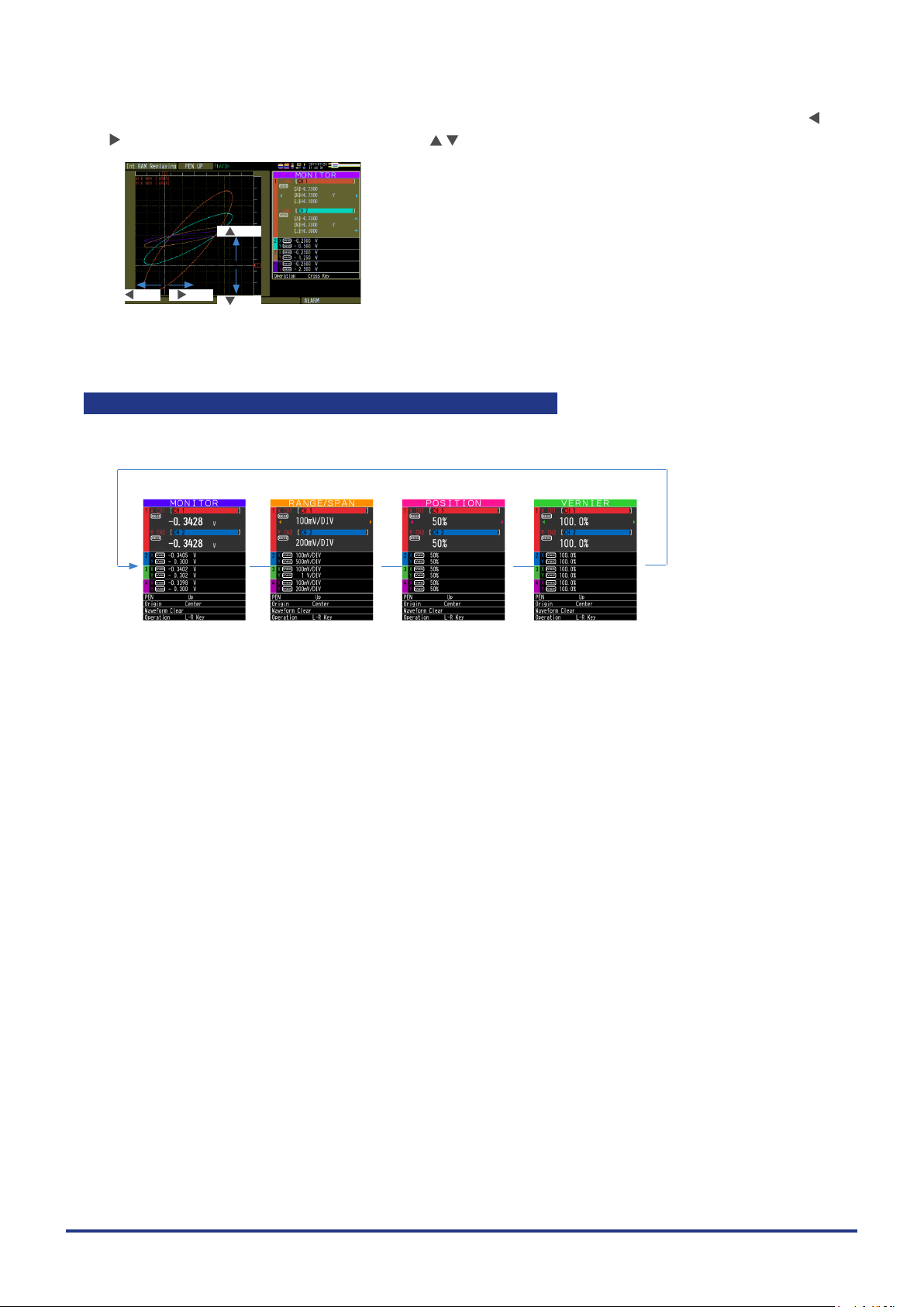
CHAPTER 3 Settings and Measurement
In the "MONITOR" display during replaying, you can move the cursor of the selected XY-CH. Use the
keys to move the X-axis cursor, and use the keys to move the Y-axis cursor.
key
key key
key
Simple setting of RANGE/SPAN/POSITION/VERNIER
Press [SPAN/TRACE/POSITION] key to perform each setting.
XT scr een
MONITOR RANGE/SPAN POSITION VERNIER
Digita l value is display.
(Default status)
The RANGE/SPAN
value (waveform
amplitu de) can be
changed.
POSIT ION (center
positi on of wavefo rm)
can be changed.
VERNIER (ne
amplitude adjustment
of wavefor m) can be
changed.
3-48
Page 93

CHAPTER 3 Settings and Measurement
Quick setting
Quick setting is a function that can be set in the Digital display without opening the setting menu.
• Pen (PEN)
Operates the pen UP/DOWN.
Use the keys to change the state of UP/DOWN.
When the pen is in DOWN state, the trajectory of the pen is drawn in the XY graph waveform.
Pen down operation is forced during capturing.
Pen UP st ate Pen DOWN state
• Origin
Initialize the XY position.
Select the Center of the XY graph or the Lower Left of the XY graph with the keys.
If [ENTER] key is pressed after selecting the origin, the XY position reference point moves to the selected
position
Origin Center O rigin Lo wer Le ft
3-49
Page 94

CHAPTER 3 Settings and Measurement
• Waveform Clear
Erase the waveform (pen trajectory) in the XY graph.
Press [ENTER] key to erase it.
• Operation mode (Operation)
[ENTE R] key
Switch the operation mode of the XY digital display.
Press the keys to switch the operation mode.
L-R Key : L-R key mode
Cross key : Cross key mode
3-50
Page 95

CHAPTER 3 Settings and Measurement
XY overwrite display
When XY waveform display is used, you can display the saved ranges from the le menu as "Waveform
screen" and the saved image le as the background image of the XY graph.
(Waveform screen image le not saved by this device are not available to view.)
Save the waveform
screen
Display as background
Overwrit e
No XY ove rwrite XY overwrite display
Background image to be overwritten is not erased even if operating the XY display clear.
Perform "Overwrite Clear" separately.
* Data is overwritten even during replaying.
Overwrite is a function to read image as image data in the background. Therefore, even if you change
the XY position and VERNIER setting etc. for the waveform displayed in the background, it will not be
reected.
For details of XY overwrite setting, refer to "3.5 Setting Menus" - "(3) DISP menu" - " XY overwrite".
3-51
Page 96

CHAPTER 3 Settings and Measurement
3.4 Operation Modes
Check the system operation status in the “Status Message”.
< Free Run ning > < Ca pturin g > <Replaying while capturing data> < Replaying >
Operation Description Simple message display
Free Running Startup status, or data is not being captured. Free Running
Capturing The data is being captured. Capturing to internal RAM
Replaying while capturing
data
Replaying Captured data is being replayed. Replaying from internal RAM
Data being captured is being replayed. Capturing and Replaying
Free Running XY
Capturing to internal memory
Capturing to SD card
Capturing to USB memory
Replaying from internal memory
Replaying from SD card
Replaying from USB memory
Operation status transition
[REVIEW] key
[START/STOP] key [REVIEW] key
Replaying while
capturing data
[QUIT ] key
When capture e nds, t he scre en
automa tical ly switches to th e replay
screen.
Free Running
[START/STOP] key
[QUIT ] key
* Data cannot be r eplayed right afte r
power-on or no data ha s yet been
captured.
The operation modes are described using the Y-T + Digital display screen.
The basic operation is the same in other screen modes.
ReplayingCapturing
3-52
Page 97

CHAPTER 3 Settings and Measurement
(1) Free Running
In Free Running, rst start the settings for data capture.
The current input signal can be viewed in the waveform or digital value.
Main operations available during Free Running
Measurement condition setting change The [MENU] key is used to change various setting items in setting
SPAN/TRACE/POSITION change The [SPAN/TRACE/POSITION] key is used to change settings.
Display mode switch The [DISPLAY] key is used to change the display mode.
File operations The [FILE] key is used to perform le-related operations.
Data replay The [REVIEW] key is used to replay captured data.
Time axis change The [TIME/DIV] key is used to change the time axis scale.
menus.
Operation of screen display
The information in the screen display can be changed by switching the channels.
The operation of screen display can be changed during Free Running, capturing, and replaying.
<Scr een display when the C H1 is selecte d
on the MO NITO R scre en during Free Ru nning >
The scale of the selected
channel is indicated.
The display cha nnel can be
switch ed by the
The selecte d channel is di splaye d without color ation .
keys.
3-53
Page 98

CHAPTER 3 Settings and Measurement
(2) Capturing
The remainin g capac ity of S D card
Elapsed time
Capture dest inati on and l e name
The captured data is saved in the Internal RAM, internal memory, SD card or USB memory during data
capture.
You can not use the [MENU] key to change the setting.
Operations available during capture
SPAN/TRACE/POSITION change Change the settings with the [SPAN/TRACE/POSITION] key.
Screen display mode switch Change the screen mode with the [DISPLAY] key.
Replay while capturing Replay the data captured while capturing
Save to device Save to the device with the [FILE] key during data capture.
Setting check Display the setting information with the [MENU] key.
Time axis change Change the time axis with the [TIME/DIV] key.
(Rema ining time more t han 99 999 h ours is
displayed as "++++:++:++".)
(3) Data replay during capturing
Displ ays the voltage at a p oint
indicated by Cu rsor A or B or the
selected cursor.
Displ ays the me asure ment t ime at a
point in dicated by Curs or A or B or th e
selected cursor.
The captured data while capturing can be replayed by pressing the [REVIEW] key.
Use the Direction keys ( ) to move the cursor and captured data to check digital values.
Operations available during capturing
Cursor movement The [CURSOR] key is used to switch between cursors A and B.
Save to device Recording save can be performed from the [FILE] menu.
Screen copy Copy the screen with the [FILE] key.
Time axis change Change the time axis with the [TIME/DIV] key.
The or
(The data up to the present or between the cursors can be saved in a
separate le during data capture.)
,
keys are used to move the cursors.
During ring capturing, the replay cannot be performed while capturing.
•
During relay capturing, the data cannot be saved to a device.
•
During relay capturing, the replay cannot be performed before the le is switched while capturing.
•
3-54
Page 99

CHAPTER 3 Settings and Measurement
(4) Replaying
Displ ays the voltage at a p oint
indicated by Cu rsor A or B or the
selected cursor.
Displ ays the me asure ment t ime at a
point in dicated by Curs or A or B or th e
selected cursor.
Displays the captured data.
Main operations available during replaying
SPAN/TRACE/POSITION change Change the settings with the [SPAN/TRACE/POSITION] key.
Operation in the menu during data capture Perform cursor movement, data search and calculation setting with the
Cursor movement Switch between Cursor A and B with the [CURSOR] key.
Data save Save all the data or data between cursors withy the [FILE] key.
Time axis change Change the time axis scale with the [TIME/DIV] key.
File operation Perform le-related operations
Display copy Copy the screen with the [FILE] key.
[MENU] key.
Using the or
,
keys, move the cursor.
For CSV-formatted data, only the data captured by the device can be replayed.
Also, when the data captured in CSV format is replayed, the unit of the temperature data is displayed as “deg
C” rather than “°C”.
3-55
Page 100

CHAPTER 3 Settings and Measurement
3.5 Setting Menus
When you press the [MENU] key during Free Running, the following menu screens appear.
(1) AMP settings
This menu is used to specify input signal-related settings.
I/F OTHERTRIGDISPAMP DATA
< Analog settings >
Setting Selections available
Input Off, DC, RMS, TEMP, RH
Range [Voltage] 20, 50, 100, 200, 500mV; 1, 2, 5, 10, 20, 50, 100, 200, 500V; 1-5V
[RMS] 10, 25, 50, 100, 250, 500mVrms
[Temperature] TC-K, TC-J, TC-T, TC-R, TC-E, TC-B, TC-S, TC-N, TC-W
[Humidity] 100% xed
Filter Line, 5, 50, 500Hz, 5k, 50kHz
EU
(Scaling settings)
Misc. Annotation text string Enter text. (Max. 31 characters)
Function Off, On
Dec pt None, 1 digit, 2 digits, 3 digits, 4 digits after the decimal point
Meas.
Value
EU value Upper limit Set numeric value.
Select Cur, Length, Area, Volume, Velocity, Accel, Freq, Mass, Energy,
Unit The selections vary depending on the unit selected in the above.
InterCH Op
Settings
Span
settings
Set waveform color 0 to 31 for each of red, green, blue (RGB)
Line Thickness Setting 1 to 8 dots
Trace Off, On
Upper limit Set numeric value.
Lower limit Set numeric value.
Lower limit Set numeric value.
Function Off, On
Operation Left-hand
Scaling /1000000, /1000, ×1, ×1000, ×1000000
Operations
span
Select Cur, Length, Area, Volume, Velocity, Accel, Freq, Mass, Energy,
Unit The selections vary depending on the unit selected in the above.
Upper limit Set numeric value.
Lower limit Set numeric value.
side
Operator +, -, ×, /
Righthand
side
Dec pt ×1, ×10, ×100, ×1000, ×10000
Upper limit Set numeric value.
Lower limit Set numeric value.
1, 2.5, 5, 10, 25, 50, 100, 250Vrms
Pressure, Flow, Temp, Strain, Brightness, Concentration; Optional
(Enter arbitrary text: Up to 8 characters)
CH number
CH number
Pressure, Flow, Temp, Strain, Brightness, Concentration; Optional
(Enter arbitrary text: Up to 8 characters)
3-56
 Loading...