

Page 1
In compliance with various test requirements, this data logger is capable
of performing high-speed simultaneous voltage and temperature measurements
High-speed isolated 8-channel multifunction logger
GL900
Data can be captured to PC-friendly
USB memory sticks
Long-term data ca n be ca ptured direc tly to built-in 256 -MB flash memory or to an
external U S B memory s tick at
sampling interva ls
from 1 ms to
1 min. F or high-s pe ed s ampling at
interv a l s fa s te r tha n 1 ms , u p to
one million data points c an be
ca ptured to internal R AM.
Example of 8-channel analog measurement
C apture des tination
Internal R AM
(up to one million points)
Internal flash memory (256 MB)
E xternal US B memory stick (5 12 MB )
The USB memory stick must be a standard model (without ngerprint recognition or other proprietary features).
an
10μs
10 seconds
Simple data transfer to desktop PC.
Enables data transfers and remote operation
100μs
500μs
×
×
1ms
Approx. 16 min.
and 40 sec.
Approx. 11 hrs.
Approx. 22 hrs.
Approx. 1 min.
Approx. 8 min.
and 40 sec.
×
×
and 20 sec.
×
×
LAN / USB
10ms
Approx. 2 hrs.
and 40 sec.
Approx. 4 days
Approx. 8 days
100ms
Approx. 1 day
and 3 hrs.
Approx. 49 days
Approx. 98 days
1s
Approx. 11 days
and 13 hrs .
Approx. 493 days
Approx. 986 days
Easy-to-use, upright, high-speed, isolated
8-channel multifunction logger
An easy-to-use upright device enabling isolated 8-channel multifunction input,
the GL900 is capable of performing high-speed simultaneous measurements of
voltage, temperature, and various other phenomena.
BNC terminal
Voltage
+/-20 mV to +/-500 V
Thermocouples:
Temperature
K, J, E, T, R, S, B, N, W
0 to 100%
Humidity
(the B-530 option is required)
4 channels
Pulse
Count, Inst., RPM
4 channels
Logic
‡ Select either Pulse or Logic
for voltage measurement
M3 screw terminal
for temperature measurement
‡ Conne ctions a re ma de to
both the BNC terminal and
M3 screw terminal for the
same channel.
Can be used an X-Y recorder
The GL900 reproduces analog X- Y recorder
movements and provides the illusion of pen
up/pen down movements. It ca n be
operated like an analog X- Y recorder and
can also be used as a 4-pen X- Y recorde r.
T he digital data format facilitates
post-mea s urement confirmation of data
values and report creation.
High precision measurement
even during high-speed sampling
Le ts use rs perform high-prec is ion temper ature measureme nts even during
high-speed sampling – ideal for performing combined voltage and temperature
measurements.
High-voltage measurement capabilities
Built-in, large-format 5.7 inch color
LCD for easy-to-read waveforms
The wide 500 V range enables 100 to 240 VAC power supply voltage waveform
measurements. Using logic input and a clamp meter simultaneously allows
measurement of a device’s power supply voltage and current concurrently with
sequential control of various points.
Sequence: Logic
Humidity: Dedicated humidity sensor
Temperature: Thermocouple
Current: Clamp meter
Voltage
AC
power supply
The bright, easy-to-read large-format 5.7-inch color TF T LCD provides vivid,
easy-to-read waveform displays. Cursor keys enable fast, easy control and
setup. The waveform display can be scrolled at high-speed – 10 ms/DIV.
5.7-inch color TFT LCD
Cursor keys
Free Running display for waveform-analysis
for non-recording usage
The Free Running display lets users check input
signal waveforms even before measurements begin.
Waveforms are displayed on each setup screen,
users can change settings while viewing the waveforms.
Easy PC measurement via USB; remote monitoring via ethernet
Web server and FTP functions
The USB and Ethernet connections enable transfer of captured data to your PC
and setup and control of the GL900 from a PC, even without the PC software
provided as standard software with the GL900.
Ethernet
Web server/FTP server functions
Wa ve form dis play a nd G L90 0 setup ope ra tions can be pe rformed v ia a we b brows er
(e.g. , Internet E xplorer). In ad dition, data files captured to the G L900 ’s interna l
memory or to a US B memory s tick c an be trans ferred or deleted from the P C.
USB drive mode
When your GL900 is connected to your PC via the USB interface, the GL900
can be operated in USB mode to enable fast, easy data transfers from internal
memory to the PC.
NT P client function
Simply connect the GL900 to an NT P server via an Ethernet connection to
synchronize GL900 time with NTP server time at periodic intervals.
TIME/DIV key
Expansion/
reduction
A
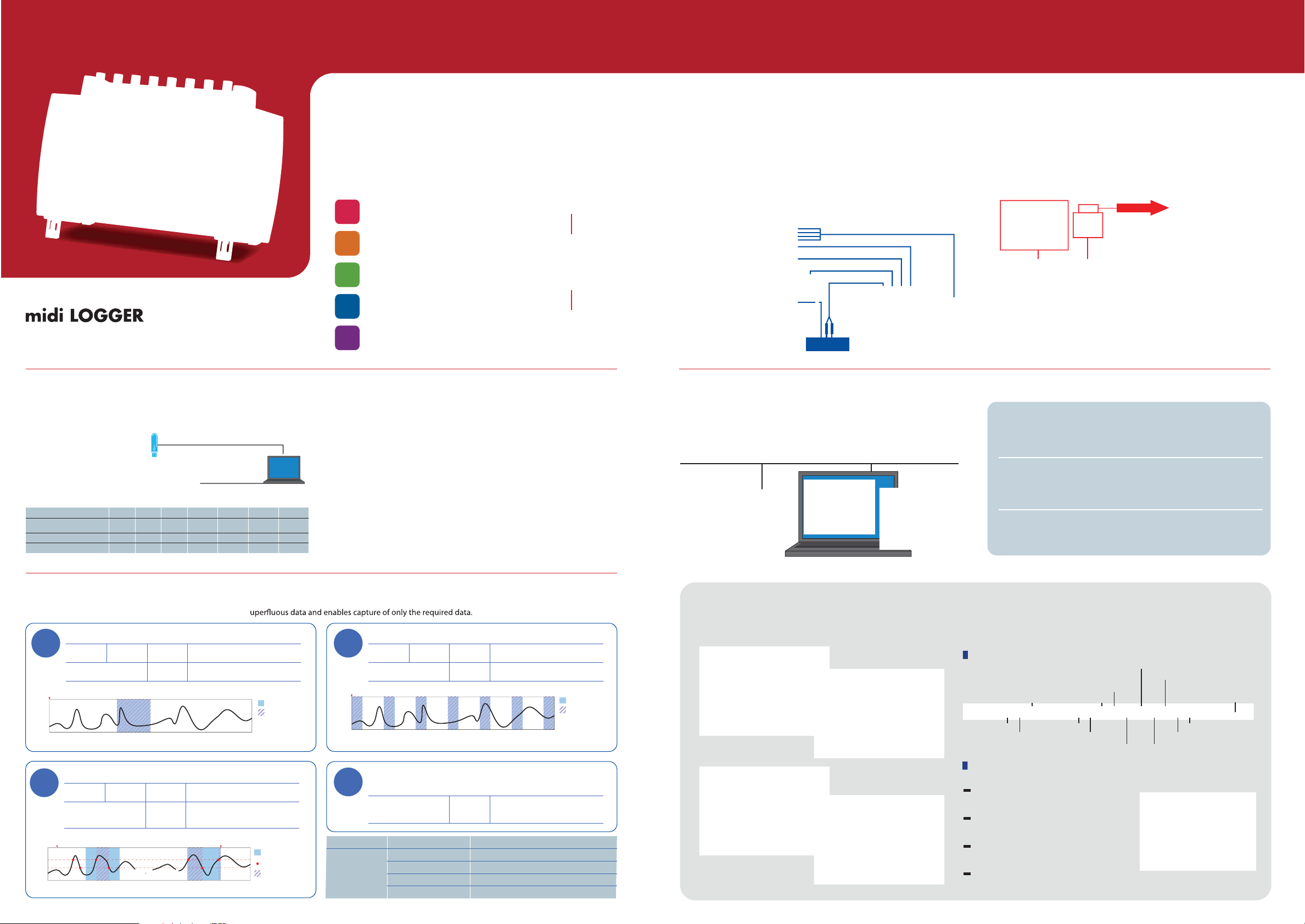
Comprehensive built-in trigger and timer functions
Using a combination of trigger and timer functions eliminates s
Setting
To perform measurement over a four-day period starting J anuary 10
example
Timer setting
1
Stop s etting J anua ry 14 23 hours 59 minutes
Trigge r s etting Start trigger O ff
Stop trigger Off
Start key On
J anua ry 1
Setting
To perform meas urements of abnormal s ignals during device operations
example
Timer setting Daily cycle S tart setting 09 hours 00 minutes
2
Stop setting 17 hours 00 minutes
Trigge r s etting Start trigger Lev el C H 1 (3 V Rising)
Stop trigger Le vel C H 1 (2 V Falling)
Rep ea t On
Start key On
S tart trigger 3 V
S top trigger 2 VS top trigger 2 V
0:00 6:00
Date and time
5 1015202530
12:00 18: 00 0:00 6:00 12:00 18:00 0:00
S tart setting January 10 00 hours 00 minutes
End of data c apture a s timer s etting takes priority
Timer period
Data capture
Timer period
T rig ger a cti vati on p oints
Data capture
Setting
To perform measurements every 20 minutes
example
Time r s etting Hour ly c yc le S ta rt se tting 00 minutes 00 s econds
3
Stop setting 20 minutes 00 seconds
Trigge r s etting S tart trigger O ff
Stop trigger Off
Start key On
0:00
Setting
To perform meas urements for a period of one h our, eve ry four hours , daily
example
With the timer set to daily cycle status, data is captured repeatedly for one hour every four hours.
4
Trigge r s etting S tart trigge r Off
Stop trigger S cheduled time (one hour)
Rep ea t On (Rep eat interval: 4 hours )
Time r settings Time r mode Off, Dat e and time , Daily c yc le, Hourly cyc le
Trigge r s ettings S tart sourc e s etting Off, Le vel value, E xternal input
S top s ource setting Off, L eve l value , Externa l input, Sc hedule d time
P re-trigger 0 -100%
Rep eat ca pture On, Off and Repe at interva l
1:00 2:00 3:00 4:00 5:00 6:00
Timer period
Data capture
Dedicated software for real-time data capture
Three measurement screens are provided to allow selection of the screen that best suits measurement needs.
The Replay screen provides a Zoom screen feature to enable enlarged display of specic sections of long-term measurement data.
Replay screen: Zoom
Measurement screen: Y-T
Measurement screen: X-Y
Measurement screen: FFT
Simple operations for various user levels.
Easy-to-use software using icon keys
for intuitive operations
Switch Relative / Absolute time
Expand time axis Expand Y axis
Reduce time axis
Move position down
Move position up
Reduce Y axis
Trace ON/OFF
Display digital values window
Convenient functions
Various convenient data-processing functions are built in.
Direct to Excel function
T his function enab les mea surem ent data to be written dire ctly
to an E xc el file.
Search function
This func tion enab les sea rching for specific val ues in the
captured data.
CSV batch conversion function
This func tion enab les batch conversion of multiple ca ptured
files to CSV file forma t.
Thumbnail function
This func tion enab les display of c aptured da ta files as thumbnails.
Display comment input window
Change screen display
Display Search window
Display cursor window
Display waveform operation window
 Loading...