

GRAPHIC WHIZARD GW12000 Instruction Manual

Graphic Wizard GW
12000 Number/Perf/
Score/Slit Machine
Instruction Manual

2283 Argentia Road, Suite 21; Mississauga, Ontario; Canada L5N 5Z2; Tel: (905) 858-7663 Fax: (905) 858-4419 Toll Free 1-800-265-3376
Web Site: www.graphicwhizard.com
GW 12000
Reference
Manual
Shown with optional second head
GRAPHIC WHIZARD
2283 Argentia Road, Suite #21
Mississauga, Ontario L5N 5Z2
Phone # (905) 858-7663 Fax # (905) 858-4419
Toll Free: 1-800-265-3376
Web Site: www.graphicwhizard.com
Version 99-04
GW 12000 - Reference Manual

Table of Contents
Page
1.0 General Operation 2
1.1 Technical Data 2
1.2 Safety Regulations 2
GW 12000 Layout 3
2.0 Machine Assembly 4
2.1 Power Supply Instructions 4
2.2 Feed Trays 5
2.3 Register Board 6
2.4 Numbering Heads 7
2.5 Conveyor Outfeed Plate 8
2.6 Additional Switches and Controls 9
3.0 Operating Keyboard 10
3.1 Running a Job 11
3.2 Stopping a Job 13
3.3 Changing Programs 13
3.4 Programming a Job 14
3.5 The Batch Function 16
3.6 The Repeat Function 17
3.7 Motor Speed Control 17
4.0 Setting Up a Job 18
4.1 Aligning the Feed Tray Guides 18
4.2 Setting Feed Tire Pressure 18
4.3 Register Board 20
4.4 Perforating/Slitting 21
4.5 Scoring 23
4.6 Idler Wheel Holders 23
4.7 Main Rollers 23
4.8 Installing Ink Pads 23
4.9 Locating the Numbering Heads 23
4.10 Setting Impression Control 24
4.11 Flatness of Impression 25
4.12 Stripper Assembly 26
4.13 Boss Support Bar 26
5.0 Running a Job 28
5.1 Setting the Starting Number 28
5.2 Setting the Repeat Selector 29
5.3 Fanning 29
6.0 Maintenance 31
6.1 Numbering Heads 31
6.2 Machine Cleaning 31
6.3 Lubrication 32
6.4 Friction Feed 32
7.0 Troubleshooting 33
Friction Feeder 33
Print Quality 33
Registration 34
Numbering Heads 34
Error Messages 35
2

1.0 General Operation
The Model GW 12000 can number on single sheets (12# bond to 12 point card or
45 to 250 gsm paper) or multi-part carbonless forms (up to 10 parts) while
simultaneously perforating, slitting and/or scoring. With proper set-up, 12000 sheets
per hour (8.5” x 11” stock with one hit) can be quickly and identically processed. The
Model GW 12000 is microprocessor controlled, making it easy to set up and program. It
has the programmability to hold a maximum of 99 jobs with 10 hits and 1 job with 100
hits. These jobs can all be stored and recalled for future use. The unique friction feeder
sends through one set at a time, even from the unglued side of a padded set. The 30"
register board ensures consistent registration and micro adjustment. Perforations are
done between the register board and main rollers, producing a straight perforation, slit
or score, avoiding tail whip. Perforating wheels are offered in a wide range of teeth
configurations and can be quickly changed using the retaining ring pliers supplied. A
photocell recognises the lead edge of the sheet and the microprocessor stops the sheet at
the specific location(s) where numbers are required. The numbering heads allow for a
maximum of four pneumatically driven units. Pneumatics allows for non-stop, tireless
operation. Finished stock is then delivered to a conveyor outfeed plate, stacking 3 to 4
times more output than a traditional chute exit tray.
1.1 TECHNICAL DATA
Areas of use:
Paper weight: 12# - 12 point (45-250 gsm)
Paper formats: max. 18” x 18” (45 x 45 cm)
min. 3” x 5” (7.6 x 12.7 cm)
Electrical configuration:
Voltage: 90-135 VAC or
180-270 VAC
Frequency: 60 Hz or
50 Hz
Fusing: 250V, 5A
1.2 SAFETY REGULATIONS
Before using the machine, you must read the operating instructions.
Professionals must only eliminate damage or extraordinary malfunctions.
Never insert your hand into the machine while it is running.
Do not wear loose fitting clothing when working with the machine.
Make sure that the machine stands on a level and well-ventilated positions.

INSERT PICTURE
GW 12000 LAYOUT
2.0 Machine Assembly
WITH THE 115V SHOWING
Remove and unpack all machine parts from the shipping carton.
2.1 Power Supply Instructions
Before connecting the power cord to a wall receptacle, make certain the supply
voltage is what the machine has been set up for. The voltage is marked on the sticker
containing the serial number of the machine. If there is any discrepancies, please call
your dealer first before plugging in the machine.
The switch module is located behind the main operator side panel, directly
underneath the register board. It also houses the main fuse.
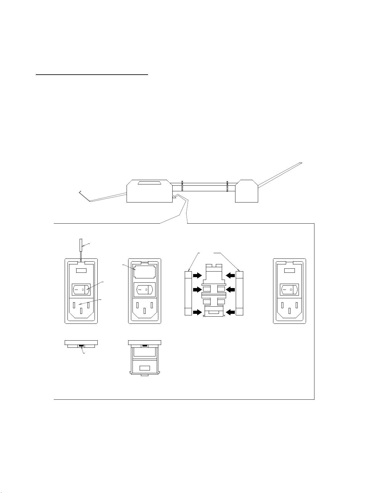
CHANGING THE FUSE IN THE SWITCH MODULE
SCREWDRIVER
FUSE
HOLDER
ON/OFF
SWITCH
CORD
RECEPTACLE
LIP
INSERT SCREWDRIVER
INTO LIP OF THE FUSE
FRAME.
OPEN THE FUSE FRAME
DOOR AND PULLOUT THE
RED FUSE HOLDER.
FUSES
INSERT TWO SLOW BLOW
FUSES RATED 250V 5A FOR
A SUPPLY VOLTAGE OF 120V.
THESE FUSES ARE 1/4 INCH
WIDE BY 1 1/4 INCHES LONG.
INSERT THE FUSE HOLDER
BACK INTO THE UNIT FRAME
THROUGH THE WINDOW.
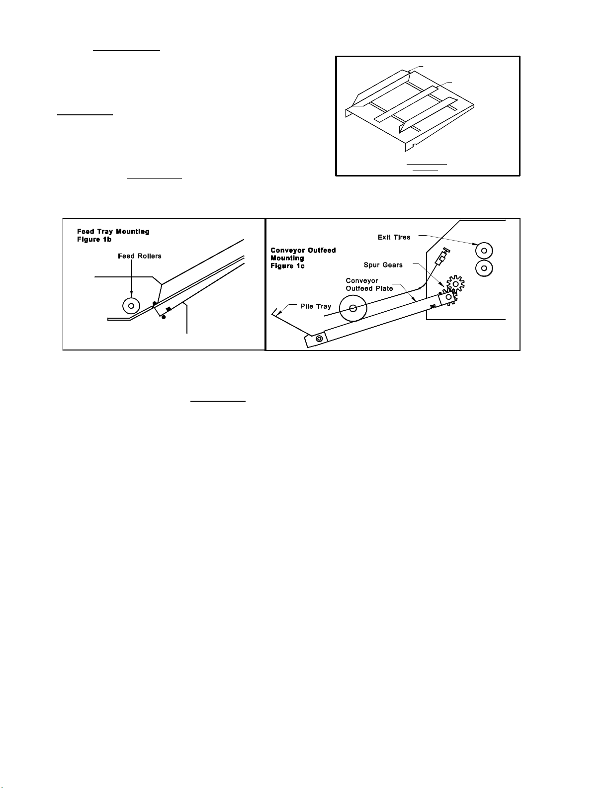
2.2 Feed Trays
The feed and exit tray assemblies are
comprised of four components each: the tray,
two tray side guides and a centre slot cover (see
Figure 1a).
The feed tray sits in the machine on
mounting pins inside the machine's side frames
as shown in Figure 1b. The tray can be easily
removed and stored elsewhere when not in use.
SIDE GUIDE
Tray Assembly
Figure 1a
CENTER SLOT GUIDE
Place the tray side guides, bottom flange towards the centre and centre slot cover
on the tray as shown in Figure 1a and screw on the nylon wing nuts to secure the pieces
on the tray. The operator side tray guide of both the feed and exit tray should be pulled
all the way over to the operator side before tightening its two wing nuts.
Note:It is critical that the operator side tray guide be moved all the way over to the
operator side of the machine to ensure that the stock being processed
through the machine passes directly underneath the
photocell. If the stock does not pass directly underneath the photocell, the
machine will not recognise sheets and the program being run will not be
initiated.
Place a pile of the stock to be processed in the feed tray and use it to align the
non-operator side tray guide to the pile. Allow a fraction of an inch so that the pile
flows freely up and down the tray if released from the top.
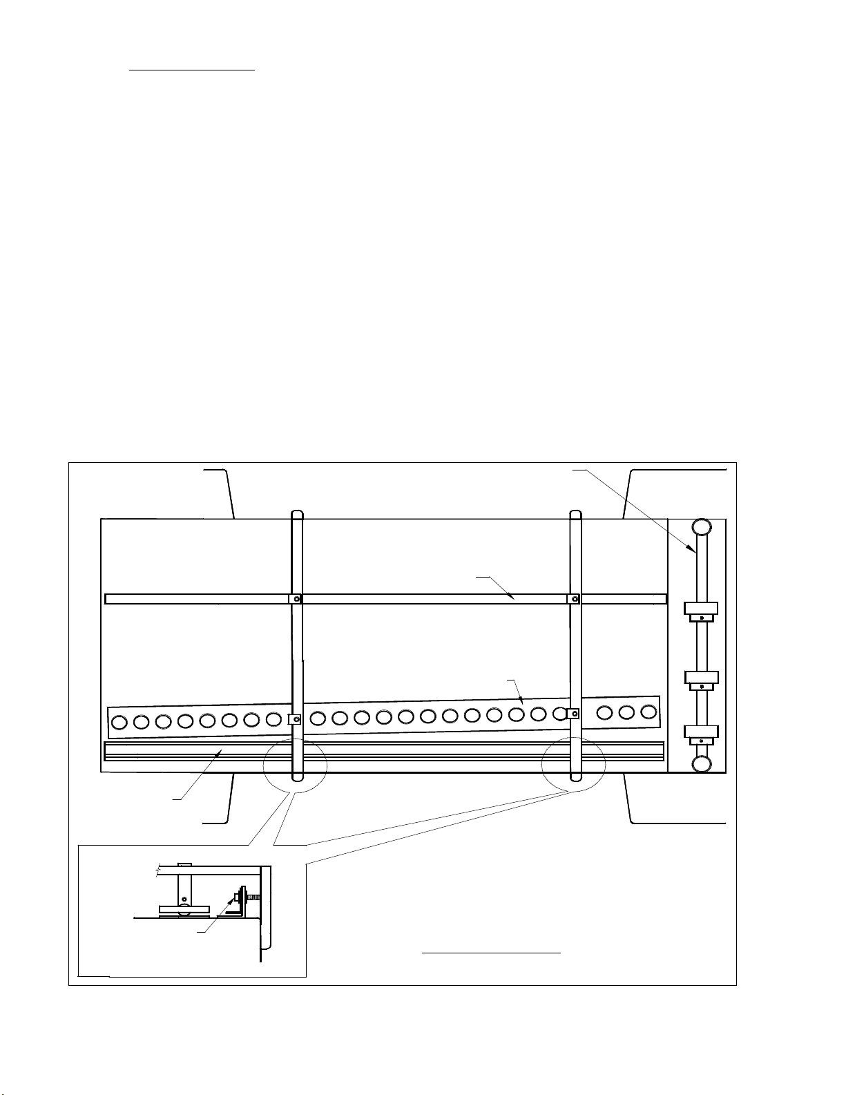
2.3 Register Board
Once stock has been feed into the machine, it immediately enters the register
board. The register board pulls all sheets to a common edge for superior registration,
ensuring all stock being processed enters the perf/score/slit and numbering section in the
same position.
With the machine, you are equipped with 2 sets of ball bearings to be used in the
register strip (see Fig.2 ). One set is metal, for heavier stocks and one set, nylon, for
lighter stocks. A mixture of the two can also be used for mid-weight stocks. To correct
feed skew or uneven cut stock, there are two register board adjustment screw on the
register board, directly underneath the two square support shafts. With the register
board adjustment screw, you can pitch the register guide, correcting stock travel into
the machine, ensuring a true, straight perf/score/slit and consistent numbering
registration. It also allows you to micro-adjust your numbering position, without having
to move the numbering head. Lastly, along the outside edge of the stock being run, there
is an outside guide for the register board, which keeps the stock flat as it travels through
the register board.
REGISTOR GUIDE
NON-OPERATOR SIDE
STOCK GUIDE
BALL BEARING HOLDER
Feed Shaft
REGISTOR GUIDE
ADJUSTMENT SCREW
Figue 2: Register Board
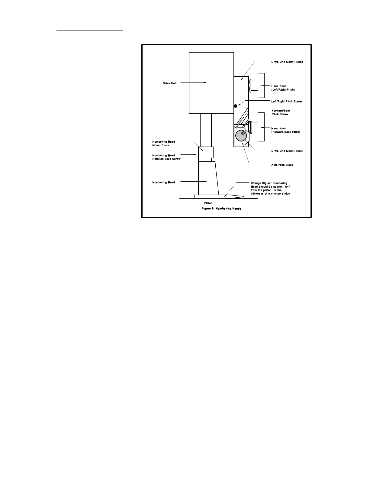
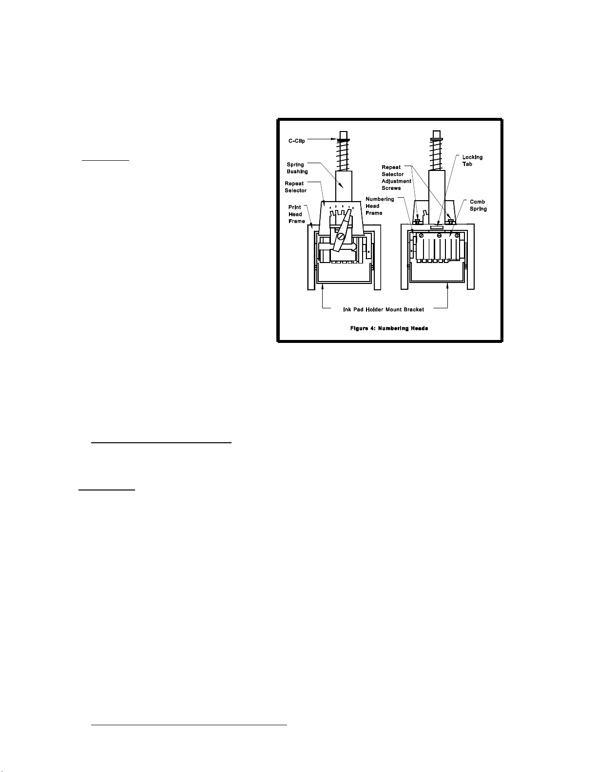
2.4 Numbering Heads
The numbering heads
are already secured to the
drive unit by two screws
through the numbering head
mount block as shown in
Figure 3. The drive unit is
then mounted to the drive
unit mount block using the
hand knob provided. While
installing the drive unit,
make sure the screw cap on
the back of the drive unit fits
in the cavity on the drive
unit mount block so that the
rubber plug provides some
pressure against the screw
cap. To do this, you may
have to back out the
left/right pitch screw. Plug in
the cord from the drive unit into the appropriate receptacle on the non-operator side
cover (closest head to the closest receptacle). If your machine is equipped with more
than one head, by convention, the numbering head and drive unit closest to the operator
control panel will be referred to as head #1(H1) and the other will be head #2 (H2).
The height of the numbering head has been factory set and it is critical to the
proper performance of the drive unit and numbering head. This distance is
approximately 3" or the thickness of a numbering wheel change stylus. However, the
numbering head must be levelled to ensure that the numbering wheels strikes the sheet
square to provide a quality inked impression and a flat crash impression on carbonless
sets. This will be discussed later (Section 4.11).
The numbering heads can operate through 360Ε. This is done by loosening the
numbering head rotation screw (using the large hexdriver supplied) located on the front
of the numbering head mount block. Once the screw is loose, the head is free to rotate.
Tighten the screw once the desired position is achieved in order to prevent any
movement during machine operation.
The standard numbering head is 3/16" (4.5mm) Gothic style, reverse order, 6
digits with 2 drop wheels. The numbering head employs a pre-inked pad, which can be
purchased in red or black. These inkpads will supply you with approximately 15,000
impressions. Uninked pads may be purchased if a different colour is required (Note:
any ink used must be a non-metal corrosive one, labelled numbering machine ink).
The numbering head comes standard with six numbering wheels (a seventh
numbering wheel is optional), the last two of which are drop wheels (this will be
discussed later). The first 5 digits may be activated only. The 6th (or 7th) digit must be
changed manually. Also available are letter prefix wheels (A-J;K-R;S-Z) and a µ prefix
wheel. Modifications are possible with new numbering head orders or by special order.
The numbering heads also have
a repeat function. The repeat selector
(see Figure 4) allows a number to be
repeated from one to four times. By
leaving the repeat selector in the "0"
position, the number will not change
when the head returns to the print
position. Using the "0" position
prevents you from having to re-set the
starting number when you are
programming a new job (this will be
discussed later). Position "1" changes
the number consecutively with each
stroke and positions "2", "3" and "4"
repeat the number 2, 3 or 4 times
respectively. The repeat functions are achieved by a mechanical ratchet action in the
numbering head. When trying to use these functions, you may have to cycle the
numbering head manually in order to match the number of repeats on a page to the
number positions on a page.
2.5 Conveyor Outfeed Plate
The conveyor outfeed plate sits in the machine on mounting pins in the side frame
(see Figure 1c). Make sure that the spur gears mesh and do not force the conveyor
outfeed plate into position. The pile tray is mounted on the end of the conveyor outfeed
plate, with two Philips screws and acts as a backstop for the finished stock.
Down the conveyor outfeed plate are two conveyor belts that transport the
finished stock to the pile tray. The conveyor belts ride on two adjustable spools, which
you can change the position of for different width stocks. The two long strippers are
then placed over the conveyor belts. The outfeed roller assembly is then placed on the
conveyor outfeed plate, with the rollers riding over the long strippers onto the conveyor
belts. The shaft on which the rollers are mounted is adjustable so you can slide the
rollers closer to the exit tires for short stock and farther away for longer stocks. With
correct placement of the rollers, you will acheive a shingling action of the processed
stock, which will stack neatly on the pile tray.
2.6 Additional Switches and Controls

The main on/off switch is located under the feed tray beside the main fuseholder
and power cord.
On the left-hand side of the operating keyboard, there are two potentiometer
knobs that control the crash strength of the numbering head, known as Impression
Controls and can be adjusted to best suit the requirements of the job. For example, you
may require stronger crash numbering for carbonless sets than for single sheet bond
paper. This adjustment can be done while the machine is stopped or running.
3.0
Operating Keyboard
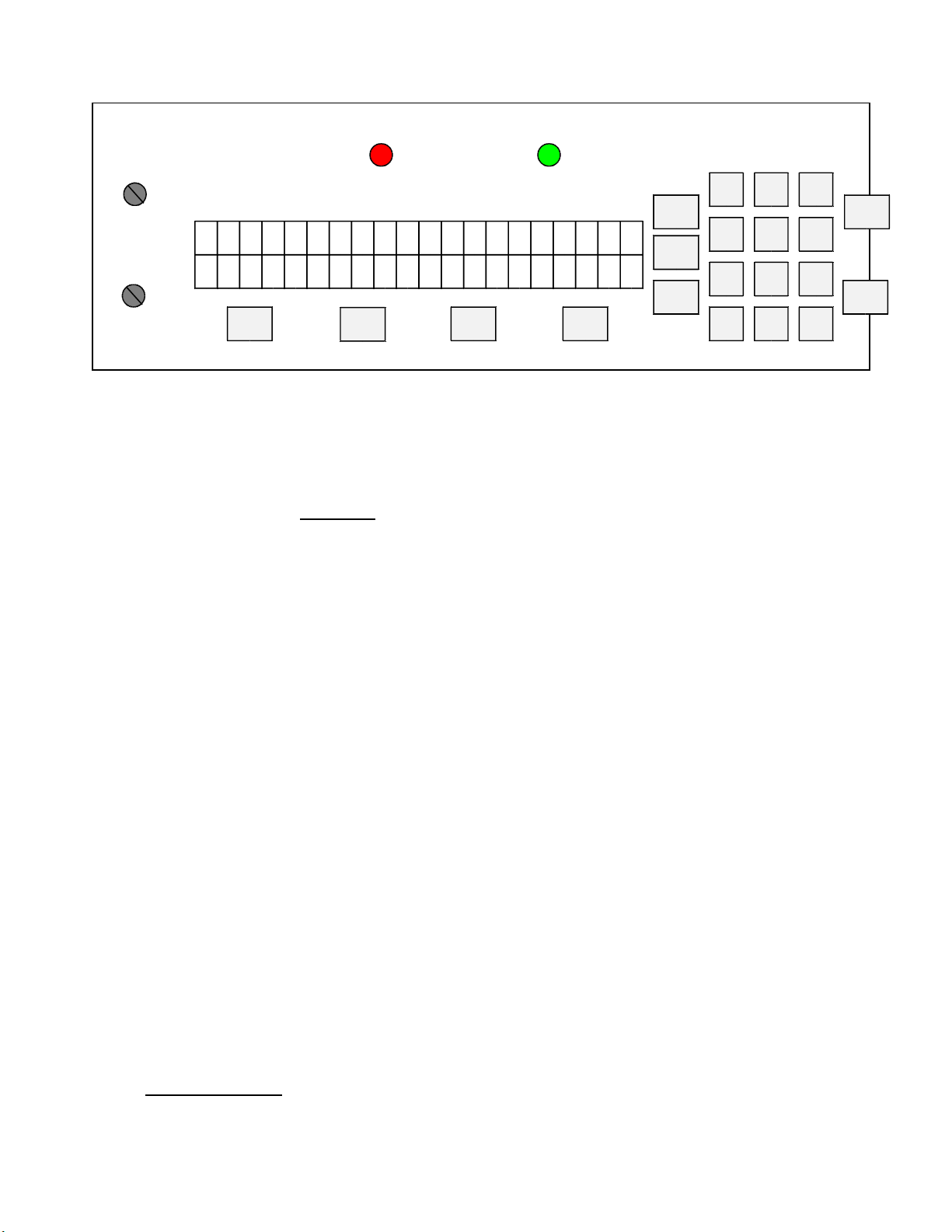
PHOTOCELL (GRN)PERF SHIELD (RED)
IMPRESSION 1
NO FUNCTION
IMPRESSION 2
G R A P H I C W H
C A N A D A
<<< F2
>>>
I Z A R D
FLASHES IF LCD ERRORFLASHES IF RAM ERROR
SETUP
SETUP
BAT
REP
F1
1 32
5
4 6
87 9
ESC ACC
0
The operating keyboard is comprised of a two line LCD display, various buttons
and two Impression Controls which consist of two potentiometer knobs that control the
crash strength of the numbering head, and can be adjusted to best suit the requirements
of the job. For example, you may require stronger crash numbering for carbonless sets
than for single sheet bond paper. This adjustment can be done while the machine is
stopped or running (see Figure 5).
The four buttons under the LCD display will perform whatever function is shown
directly above them on the bottom line of the LCD display. They may not always be
active (this is the case for the other buttons as well). Three specific function buttons
(SET UP, BAT, REP) are situated beside the display. A numeric keypad, an ‘ESC’
(escape), ‘ACC’ (accept), ‘START’ and ‘STOP’ button rounds out the rest of the
keyboard. The 'ESC' button can be used at almost any time (except during actual
running) in order to return to the previously viewed menu. The functions of the rest of
the buttons will be discussed later in this section.
Once you have plugged the machine in, turn the on/off switch to the 'on' position.
The microprocessor does an internal system check and the above will flash on the
screen.
START
STOP
3.1 Running a Job
The Idle Mode is displayed below. From this menu, you can change the motor
speed, modify your paper count and select your program.
 Loading...